EP3352954B1 - Greifvorrichtung - Google Patents
Greifvorrichtung Download PDFInfo
- Publication number
- EP3352954B1 EP3352954B1 EP16763490.6A EP16763490A EP3352954B1 EP 3352954 B1 EP3352954 B1 EP 3352954B1 EP 16763490 A EP16763490 A EP 16763490A EP 3352954 B1 EP3352954 B1 EP 3352954B1
- Authority
- EP
- European Patent Office
- Prior art keywords
- clamping
- gripping
- base part
- component
- gripping device
- Prior art date
- Legal status (The legal status is an assumption and is not a legal conclusion. Google has not performed a legal analysis and makes no representation as to the accuracy of the status listed.)
- Active
Links
Images
Classifications
-
- B—PERFORMING OPERATIONS; TRANSPORTING
- B25—HAND TOOLS; PORTABLE POWER-DRIVEN TOOLS; MANIPULATORS
- B25J—MANIPULATORS; CHAMBERS PROVIDED WITH MANIPULATION DEVICES
- B25J15/00—Gripping heads and other end effectors
- B25J15/0009—Gripping heads and other end effectors comprising multi-articulated fingers, e.g. resembling a human hand
-
- B—PERFORMING OPERATIONS; TRANSPORTING
- B25—HAND TOOLS; PORTABLE POWER-DRIVEN TOOLS; MANIPULATORS
- B25J—MANIPULATORS; CHAMBERS PROVIDED WITH MANIPULATION DEVICES
- B25J15/00—Gripping heads and other end effectors
- B25J15/0052—Gripping heads and other end effectors multiple gripper units or multiple end effectors
-
- B—PERFORMING OPERATIONS; TRANSPORTING
- B25—HAND TOOLS; PORTABLE POWER-DRIVEN TOOLS; MANIPULATORS
- B25J—MANIPULATORS; CHAMBERS PROVIDED WITH MANIPULATION DEVICES
- B25J15/00—Gripping heads and other end effectors
- B25J15/06—Gripping heads and other end effectors with vacuum or magnetic holding means
-
- B—PERFORMING OPERATIONS; TRANSPORTING
- B25—HAND TOOLS; PORTABLE POWER-DRIVEN TOOLS; MANIPULATORS
- B25J—MANIPULATORS; CHAMBERS PROVIDED WITH MANIPULATION DEVICES
- B25J15/00—Gripping heads and other end effectors
- B25J15/08—Gripping heads and other end effectors having finger members
-
- B—PERFORMING OPERATIONS; TRANSPORTING
- B25—HAND TOOLS; PORTABLE POWER-DRIVEN TOOLS; MANIPULATORS
- B25J—MANIPULATORS; CHAMBERS PROVIDED WITH MANIPULATION DEVICES
- B25J15/00—Gripping heads and other end effectors
- B25J15/08—Gripping heads and other end effectors having finger members
- B25J15/10—Gripping heads and other end effectors having finger members with three or more finger members
Definitions
- the invention relates to an anthropomorphic gripping device with a base part and with gripping fingers movably arranged on the base part for gripping gripping components.
- Anthropomorphic gripping devices are modeled on a human hand and have an arrangement of movable gripping fingers that correspond to human fingers.
- Such gripping devices are primarily used for picking up, holding, moving or moving components. It has been shown that it is difficult with comparatively small gripping devices to grip comparatively heavy components. In particular, comparatively high gripping forces are required for this. With anthropomorphic grippers in particular, it is difficult to grip and handle components between the gripper fingers that have a certain weight, the center of gravity of which lies outside an imaginary line between the gripper fingers and / or on which higher or unpredictable external forces act during handling. In particular with anthropomorphic grippers, which are used, for example, in kitchen robots, there has been the gripping of pans or pots, for example turned out to be problematic. Gripping bread slicing knives, for example, and using them to cut bread is also problematic.
- a non-movable finger has a suction mechanism at its free end, with which a component to be gripped can additionally be held by suction.
- a non-anthropomorphic gripping device which comprises a magnetized disk fastened by means of a screw connection for holding a component.
- a non-anthropomorphic gripping device for lifting and moving an engine block is from the US 5,588,794 A known.
- the present invention has for its object to provide an anthropomorphic gripping device of the type mentioned, which remedies the disadvantages mentioned.
- the gripping device also provides a tensioning device which can be actuated independently of the gripping fingers.
- the gripping fingers can be used in particular to grip gripping components which are distinguished by the fact that they do not provide any holding sections for interacting with the tensioning device.
- Such gripping is particularly advantageous for comparatively small and light components. If large or heavy components are now to be gripped, the gripping force with which the gripping fingers are pressed against the component is often not sufficient.
- Components of this type which are then designed as clamping components, can be fixed to the base part with the clamping device provided on the base part and can thus be handled.
- Such clamping components are therefore characterized in that they provide holding sections which are suitable for interacting with the clamping device provided on the base part. Depending on the component to be handled, it can therefore be gripped by the gripping device between the gripping fingers or fixed to the base part with the clamping device.
- An anthropomorphic gripping device can be used in particular in connection with service robots, such as for example in kitchen robots. With such robots, objects such as pots, pans, knives or the like can be handled, which cannot be accomplished using the gripping fingers.
- the tensioning device can in particular cooperate in a form-fitting manner with the holding section in such a way that forces can be transmitted into the base part via the tensioning device and the holding section.
- the clamping device has displaceable locking elements which engage behind the holding section or sections for fixing the clamping component to the base part in a locking position and which release the holding section or sections to release the clamping component from the base part in a release position.
- locking elements By providing such locking elements, a mechanical locking of the respective clamping component on the base part can thus be realized, with which, in particular, comparatively heavy clamping components can also be handled safely with the gripping device.
- spring elements are provided which urge the locking elements into the locking position or release position and / or if drive means are provided with which the locking elements can be moved into the release position or locking position.
- drive means are provided with which the locking elements can be moved into the release position or locking position.
- the locking elements are pushed into the locking position by the spring elements.
- the locking elements can be actuated into the release position in particular mechanically, electromagnetically, pneumatically and / or fluidically.
- the locking elements are designed in such a way that when the clamping component is fixed to the gripping device, they are first pushed from the holding sections out of the locking position into the release position, for example against the spring force of the spring element. It is advantageous if the locking elements automatically snap or snap into this locking end position when a fixing end position is reached. This can be done in particular by the spring force of the spring elements. When latching or snapping, as already mentioned, the locking elements can preferably securely engage behind the holding sections on the clamping component side.
- the clamping device as such can also be designed as a magnetic clamping device.
- the holding sections can then be fixed to the base part by means of magnetic forces. This has the advantage that no mechanically movable components have to be provided when fixing the clamping component to the base part.
- the magnetic forces are provided by means of permanent magnets and if the magnetic forces are compensated for by means of electromagnetic fields to release the clamping component from the base part.
- the electromagnetic fields can be generated in particular by electromagnets provided in or on the base part. By appropriately energizing the electromagnets, the magnetic field generated by the permanent magnets can consequently be neutralized, as a result of which the clamping component can be detached from the base part.
- the tensioning device can also be designed as a suction tensioning device, with the holding sections being fixed by means of forces provided by underpressure or overpressure.
- the clamping component it is conceivable for the clamping component to be held on the base part by means of negative pressure.
- the clamping device is designed as a bayonet clamping device, in which for clamping the holding sections are first moved along a straight line, which preferably runs orthogonally to the surface of the section of the base part having the clamping device, and then about an axis of rotation into a locking position.
- the clamping device as such can in particular have a clamping receptacle for receiving a clamping projection provided on the component to be fixed and having the holding section.
- the clamping projection is then inserted into the clamping receptacle for fixing the clamping component and locked there.
- the locking can in particular, as stated, take place via locking elements. Locking is also possible, in particular, magnetically or pneumatically.
- the clamping device has a clamping projection for engaging in a clamping receptacle provided on the clamping component to be fixed.
- the clamping components are not intended to provide a protrusion, for example in order to be able to be handled manually.
- the overhang, with locking elements to be provided, for example, is then arranged on the base part.
- a gripping system which comprises a gripping device according to the invention and an associated clamping component, the clamping component having holding sections which interact with the clamping device.
- the system is thus characterized in that the clamping components can be securely fixed to the gripping device and can be handled by providing corresponding holding sections.
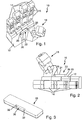
- gripping device 10 is designed as an anthropomorphic gripper, which is modeled on a human hand.
- a total of four gripping fingers 14 running parallel to one another are provided on a base part 12, each of which has three finger members 16 that are movably arranged with respect to one another.
- a further gripping finger 18 is provided on the base part 12, which should correspond to the human thumb.
- the base part 12 has a palm section 20 on the side on which the gripping finger 18 is provided on the base part 12. How from Figure 1 and 2 clear a clamping device 22 is provided on the palm section 20.
- the tensioning device 22 is designed as a tension protrusion, ie it is provided on the palm section 20 and projects above it.
- the tensioning device 22 comprises a cuboid housing 24, in which two locking elements 26, which are displaceable towards and away from one another, are provided. Spring elements are provided in the housing 24, which force the locking elements 26 axially outward from one another. The locking elements 26 can consequently be moved towards one another counter to the spring force of these spring elements.
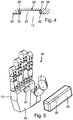
- FIG. 3 A clamping component 28 is now shown, which is to be handled with the gripping device 10.
- This clamping component 28 has a holding section 30 in the form of a clamping receptacle, which is provided to cooperate with the clamping device 22.
- the holding section 30 comprises two rear grip sections 32 which are on the base part 12 fixed state of the locking elements 26, as in Figure 4 shown to be attacked.
- the locking elements 26 are formed on the upper side facing away from the palm section 20 in such a way that when the gripping device 10 or the tensioning device 22 is moved into the holding section 30 against the spring force of the spring elements from the in FIG Figure 1 and 2 locking position shown to be pushed towards each other in a release position, and that when they reach the in Figure 4 Lock position shown in the locking position automatically due to the spring preload.
- the clamping component 28 is thus securely fixed to the base part 12.
- the locking elements 26 can be moved towards one another by the drive means, as a result of which they move into the housing 24.
- the tensioning device 22 can thus be moved out of the holding section 30.
- the gripping device 40 shown corresponds to the gripping device 10, with corresponding components being identified by corresponding reference symbols.
- the clamping device 22 is designed as a magnetic clamping device.
- the clamping device 22 there comprises a comparatively strong permanent magnet which interacts with a ferromagnetic holding section 30 provided on the clamping component 28.
- the clamping device 22 consequently engages in the holding section 30 designed as a clamping receptacle.
- the clamping component 28 is then fixed via magnetic forces.
- electromagnets are provided in the tensioning device 22 or in the base part 12, with which electromagnetic fields can be generated which compensate or neutralize the magnetic forces with which the tensioning component 28 is fixed on the base part 12. The clamping component 28 can then be released from the gripping device 10.
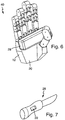
- a clamping component 28 is shown, which is designed as a knife.
- the holding section 30, which, depending on the embodiment, interacts with either the gripping device 10 or the gripping device 40 for fixing the clamping component 28 can be clearly seen.
- the gripping devices 10 and 40 have the advantage that not only small and light components can be gripped with them, but also components that are comparatively heavy or bulky can be securely fixed to the gripping device by means of the clamping devices 22.
Landscapes
- Engineering & Computer Science (AREA)
- Robotics (AREA)
- Mechanical Engineering (AREA)
- Manipulator (AREA)
Description
- Die Erfindung betrifft eine anthropomorphe Greifvorrichtung mit einem Basisteil und mit am Basisteil beweglich angeordneten Greiffingern zum Greifen von Greifbauteilen.
- Anthropomorphe Greifvorrichtungen sind einer menschlichen Hand nachgebildet und weisen eine Anordnung von beweglichen Greiffingern auf, die den menschlichen Fingern entsprechen.
- Derartige Greifvorrichtungen dienen in erster Linie zum Aufnehmen, Halten, Umsetzen oder Verlagern von Bauteilen. Es hat sich gezeigt, dass es mit vergleichsweise kleinen Greifvorrichtungen schwierig ist, vergleichsweise schwere Bauteile zu greifen. Insbesondere sind dazu vergleichsweise hohe Greifkräfte nötig. Gerade bei anthropomorphen Greifern ist es schwierig, zwischen den Greiffingern Bauteile sicher zu greifen und handzuhaben, die ein gewisses Gewicht aufweisen, deren Schwerpunkt außerhalb einer gedachten Linie zwischen den Greiffingern liegt und/oder auf welche bei der Handhabung höhere oder unvorhersehbare äußere Kräfte wirken. Insbesondere bei anthropomorphen Greifern, die beispielsweise bei Küchenrobotern zum Einsatz kommen, hat sich beispielsweise das Greifen von Pfannen oder Töpfen als problematisch herausgestellt. Auch das Greifen von beispielsweise Brotschneidemessern und deren Verwendung zum Brotschneiden ist problematisch.
- Eine weitere anthropomorphe Greifvorrichtung ist aus der
US 2012/059517A1 bekannt. Bei dieser Greifvorrichtung weist ein nicht beweglicher Finger an seinem freien Ende einen Saugmechanismus auf, mit dem ein zu greifendes Bauteil zusätzlich durch Ansaugen gehalten werden kann. - Aus der
FR 2 979 564 A3 - Eine nicht anthropomorphe Greifvorrichtung zum Anheben und verlagern eines Motorblocks ist aus der
US 5 588 794 A bekannt. - Der vorliegenden Erfindung liegt die Aufgabe zugrunde, eine anthropomorphe Greifvorrichtung der eingangs genannten Art bereitzustellen, die den genannten Nachteilen Abhilfe leistet.
- Diese Aufgabe wird mit einer Greifvorrichtung mit den Merkmalen des Anspruchs 1 gelöst.
- Folglich sieht die Greifvorrichtung neben den Greiffingern zusätzlich eine Spanneinrichtung vor, die unabhängig von den Greiffingern betätigbar ist. Mit den Greiffingern können insbesondere Greifbauteile, die sich dadurch auszeichnen, dass sie keine Halteabschnitte zum Zusammenwirken mit der Spanneinrichtung vorsehen, gegriffen werden. Ein derartiges Greifen ist insbesondere für vergleichsweise kleine und leichte Bauteile vorteilhaft. Sollen nun große oder schwere Bauteile gegriffen werden, so reicht die Greifkraft, mit der die Greiffinger gegen das Bauteil beaufschlagt werden, häufig nicht aus. Derartige Bauteile, die dann als Spannbauteile ausgebildet sind, können mit der am Basisteil vorgesehenen Spanneinrichtung am Basisteil fixiert werden und somit gehandhabt werden. Solche Spannbauteile zeichnen sich also dadurch aus, dass sie Halteabschnitte vorsehen, die dafür geeignet sind, mit der am Basisteil vorgesehenen Spanneinrichtung zusammenzuwirken. Je nach handzuhabendem Bauteil kann dieses folglich von der Greifvorrichtung zwischen den Greiffingern gegriffen werden oder mit der Spanneinrichtung am Basisteil fixiert werden.
- Eine erfindungsgemäße anthropomorphe Greifvorrichtung kann insbesondere im Zusammenhang mit Servicerobotern Verwendung finden, wie beispielsweise bei Küchenrobotern. Mit derartigen Robotern können Gegenstände, wie Töpfe, Pfannen, Messer oder dergleichen gehandhabt werden, was mittels den Greiffingern nicht bewerkstelligt werden kann.
- Die Spanneinrichtung kann dabei insbesondere formschlüssig mit dem Halteabschnitt derart zusammenwirken, dass über die Spanneinrichtung und den Halteabschnitt Kräfte in das Basisteil übertragen werden können.
- Dabei ist vorteilhaft, wenn die Spanneinrichtung verlagerbare Verriegelungselemente aufweist, die zur Fixierung des Spannbauteils am Basisteil in einer Verriegelungslage den oder die Halteabschnitte hintergreifen und die zum Lösen des Spannbauteils vom Basisteil in einer Freigabelage den oder die Halteabschnitte freigeben. Durch das Vorsehen solcher Verriegelungselemente kann also eine mechanische Verriegelung des jeweiligen Spannbauteils am Basisteil realisiert werden, mit der insbesondere auch vergleichsweise schwere Spannbauteile sicher mit der Greifvorrichtung gehandhabt werden können.
- Dabei ist vorteilhaft, wenn Federelemente vorgesehen sind, die die Verriegelungselemente in die Verriegelungslage bzw. Freigabelage drängen und/oder wenn Antriebsmittel vorgesehen sind, mit denen die Verriegelungselemente in die Freigabelage bzw. Verriegelungslage bewegbar sind. Insbesondere hat sich dabei herausgestellt, dass es vorteilhaft ist, wenn die Verriegelungselemente von den Federelementen in die Verriegelungslage gedrängt werden. Ein Betätigen der Verriegelungselemente in die Freigabelage kann dabei insbesondere mechanisch, elektromagnetisch, pneumatisch und/oder fluidisch erfolgen.
- Besonders vorteilhaft ist, wenn die Verriegelungselemente derart ausgebildet sind, dass sie beim Fixieren des Spannbauteils an der Greifvorrichtung zunächst von den Halteabschnitten aus der Verriegelungslage in die Freigabelage gedrängt werden, beispielsweise entgegen der Federkraft der Federelement. Dabei ist vorteilhaft, wenn die Verriegelungselemente bei Erreichen einer Fixierendlage selbsttätig in diese Verriegelungsendlage einrasten oder einschnappen. Dies kann insbesondere durch die Federkraft der Federelemente erfolgen. Beim Einrasten oder Einschnappen können, wie bereits angesprochen, die Verriegelungselemente die spannbauteilseitigen Halteabschnitte vorzugsweise sicher hintergreifen.
- Die Spanneinrichtung als solche kann auch als Magnetspanneinrichtung ausgebildet sein. Eine Fixierung der Halteabschnitte am Basisteil kann dann über magnetische Kräfte erfolgen. Dies hat den Vorteil, dass bei der Fixierung des Spannbauteils am Basisteil keine mechanisch bewegbaren Bauteile vorgesehen werden müssen.
- Dabei ist vorteilhaft, wenn die magnetischen Kräfte mittels Dauermagneten bereitgestellt werden und wenn zum Lösen des Spannbauteils vom Basisteil die magnetischen Kräfte mittels elektromagnetischer Felder kompensiert werden. Die elektromagnetischen Felder können insbesondere durch im oder am Basisteil vorgesehene Elektromagnete erzeugt werden. Durch entsprechendes Bestromen der Elektromagnete kann folglich das von den Dauermagneten erzeugte Magnetfeld neutralisiert werden, wodurch das Spannbauteil vom Basisteil gelöst werden kann.
- Die Spanneinrichtung kann ferner als Saugspanneinrichtung ausgebildet sein, wobei eine Fixierung der Halteabschnitte über durch Unter- oder Überdruck bereitgestellte Kräfte erfolgt. Insbesondere ist denkbar, dass zur Fixierung des Spannbauteils dieses mittels Unterdruck am Basisteil gehalten wird.
- Ferner ist denkbar, dass die Spanneinrichtung als Bajonettspanneinrichtung ausgebildet ist, bei der zum Spannen die Halteabschnitte zunächst entlang einer geraden Linie, die vorzugsweise orthogonal zur Oberfläche des die Spanneinrichtung aufweisenden Abschnitts des Basisteils verläuft, und dann um eine Drehachse in eine Verriegelungslage bewegt werden.
- Die Spanneinrichtung als solche kann insbesondere eine Spannaufnahme zur Aufnahme eines am zu fixierenden Bauteil vorgesehenen, den Halteabschnitt aufweisenden, Spannüberstand aufweisen. Der Spannüberstand wird dann zur Fixierung des Spannbauteils in die Spannaufnahme eingeführt und dort verriegelt. Die Verriegelung kann dabei insbesondere, wie ausgeführt, über Verriegelungselemente erfolgen. Eine Verriegelung ist allerdings auch insbesondere magnetisch oder pneumatisch möglich.
- Andererseits ist denkbar, dass die Spanneinrichtung einen Spannüberstand zum Eingreifen in eine am zu fixierenden Spannbauteil vorgesehene Spannaufnahme aufweist. Dies ist insbesondere dann vorteilhaft, wenn die Spannbauteile keinen Überstand vorsehen sollen, um beispielsweise auch manuell gehandhabt werden zu können. Der Spannüberstand, mit beispielsweise vorzusehenden Verriegelungselementen, ist dann am Basisteil angeordnet.
- Die eingangs genannte Aufgabe wird auch gelöst durch ein Greifsystem, das eine erfindungsgemäße Greifvorrichtung und ein zugehöriges Spannbauteil umfasst, wobei das Spannbauteil mit der Spanneinrichtung zusammenwirkende Halteabschnitte aufweist. Das System zeichnet sich also dadurch aus, dass die Spannbauteile durch Vorsehen entsprechender Halteabschnitte sicher an der Greifvorrichtung fixiert und an dieser gehandhabt werden können.
- Weitere Einzelheiten und vorteilhafte Ausgestaltungen der Erfindung sind der nachfolgenden Beschreibung zu entnehmen, anhand derer verschiedene Ausführungsformen der Erfindung näher beschrieben und erläutert sind.
- Es zeigen:
- Figur 1 und Figur 2
- verschiedene Ansichten einer erfindungsgemäßen Greifvorrichtung,
- Figur 3
- ein Spannbauteil,
- Figur 4
- einen Ausschnitt durch einen Schnitt des in
Figur 3 gezeigten Spannbauteils in Fixierendlage, - Figur 5
- eine zweite erfindungsgemäße Greifvorrichtung mit Spannbauteil,
- Figur 6
- die Greifvorrichtung gemäß
Figur 5 mit fixiertem Spannbauteil, und - Figur 7
- ein Spannbauteil in Form eines Küchenmessers.
- Die in den
Figuren 1 und 2 gezeigte Greifvorrichtung 10 ist als anthropomorpher Greifer ausgebildet, der einer menschlichen Hand nachempfunden ist. An einem Basisteil 12 sind insgesamt vier parallel zueinander verlaufende Greiffinger 14 vorgesehen, die jeweils drei beweglich zueinander angeordnete Fingerglieder 16 aufweisen. Zudem ist am Basisteil 12 ein weiterer Greiffinger 18 vorgesehen, der dem menschlichen Daumen entsprechen soll. - Das Basisteil 12 weist auf der Seite, an der der Greiffinger 18 am Basisteil 12 vorgesehen ist, einen Handflächenabschnitt 20 auf. Wie aus
Figur 1 und 2 deutlich wird, ist am Handflächenabschnitt 20 eine Spanneinrichtung 22 vorgesehen. Die Spanneinrichtung 22 ist als Spannüberstand ausgebildet, d.h. sie ist auf dem Handflächenabschnitt 20 vorgesehen und überragt diesen. Die Spanneinrichtung 22 umfasst dabei ein quaderförmiges Gehäuse 24, in dem zwei aufeinander zu und voneinander weg verlagerbare Verriegelungselemente 26 vorgesehen sind. Im Gehäuse 24 sind dabei Federelemente vorgesehen, die die Verriegelungselemente 26 nach axial außen voneinander wegdrängen. Die Verriegelungselemente 26 können folglich entgegen der Federkraft dieser Federelemente aufeinander zu bewegt werden. Ferner sind nicht dargestellte Antriebsmittel vorgesehen, mit denen die Verriegelungselemente aus der in denFiguren 1 und 2 gezeigten Verriegelungslage in eine Freigabelage bewegt werden können, in welcher die Verriegelungselemente aufeinander zu in das Gehäuse 24 einrücken. Die Antriebsmittel können beispielsweise elektrisch, mechanisch, pneumatisch oder fluidisch betätigbar sein. InFigur 3 ist nun ein Spannbauteil 28 gezeigt, welches mit der Greifvorrichtung 10 gehandhabt werden soll. Dieses Spannbauteil 28 weist einen Halteabschnitt 30 in Form einer Spannaufnahme auf, welcher dazu vorgesehen ist, mit der Spanneinrichtung 22 zusammenzuwirken. Der Halteabschnitt 30 umfasst zwei Hintergriffsabschnitte 32, die im am Basisteil 12 fixierten Zustand von den Verriegelungselementen 26, wie inFigur 4 gezeigt, hintergriffen werden. - Die Verriegelungselemente 26 sind dabei auf der dem Handflächenabschnitt 20 abgewandten Oberseite derart keilartig ausgebildet, dass sie beim Bewegen der Greifvorrichtung 10 bzw. der Spanneinrichtung 22 in den Halteabschnitt 30 entgegen der Federkraft der Federelemente aus der in
Figur 1 und 2 gezeigten Verriegelungslage aufeinander zu in eine Freigabelage gedrängt werden, und dass sie beim Erreichen der inFigur 4 gezeigten Fixierendlage in die Verriegelungslage aufgrund der Federvorspannung selbsttätig einrasten. Damit ist das Spannbauteil 28 sicher am Basisteil 12 fixiert. - Zum Lösen des Spannbauteils 28 können, wie bereits angesprochen, die Verriegelungselemente 26 durch die Antriebsmittel aufeinander zu bewegt werden, wodurch sie in das Gehäuse 24 einrücken. Damit kann die Spanneinrichtung 22 aus dem Halteabschnitt 30 herausbewegt werden.
- Aufgrund der quaderförmigen Ausbildung der Spanneinrichtung 22 und der entsprechend komplementären Ausbildung des Halteabschnitts 30, entsteht zwischen der Spanneinrichtung und dem Halteabschnitt ein Formschluss. Dadurch können insbesondere Querkräfte und Momente sicher vom zu greifenden Bauteil in das Basisteil abgeleitet werden.
- Die in den
Figuren 5 und6 gezeigte Greifvorrichtung 40 entspricht der Greifvorrichtung 10, wobei entsprechende Bauteile mit entsprechenden Bezugszeichen gekennzeichnet sind. Im Unterschied zur Greifvorrichtung 10 ist bei Greifvorrichtung 40 die Spanneinrichtung 22 als Magnetspanneinrichtung ausgebildet. Die Spanneinrichtung 22 umfasst dort einen vergleichsweise starken Permanentmagneten, der mit einem am Spannbauteil 28 vorgesehenen ferromagnetischen Halteabschnitt 30 zusammenwirkt. Zur Fixierung des Spannbauteils 28 am Basisteil 12 rückt folglich die Spanneinrichtung 22 in den als Spannaufnahme ausgebildeten Halteabschnitt 30 ein. Die Fixierung des Spannbauteils 28 erfolgt dann über magnetische Kräfte. Zum Lösen der Fixierung ist denkbar, dass in der Spanneinrichtung 22 oder im Basisteil 12 Elektromagnete vorgesehen sind, mit denen elektromagnetische Felder erzeugt werden können, die die magnetischen Kräfte, mit denen das Spannbauteil 28 an dem Basisteil 12 fixiert wird, kompensieren bzw. neutralisieren. Das Spannbauteil 28 kann dann von der Greifvorrichtung 10 gelöst werden. - In
Figur 7 ist ein Spannbauteil 28 dargestellt, das als Messer ausgebildet ist. Deutlich zu erkennen ist der Halteabschnitt 30, der je nach Ausführungsform, entweder mit der Greifvorrichtung 10 oder der Greifvorrichtung 40 zur Fixierung des Spannbauteils 28 zusammenwirkt. - Die Greifvorrichtungen 10 und 40 haben den Vorteil, dass mit ihnen nicht nur kleine und leichte Bauteile gegriffen werden können, sondern es können auch Bauteile, die vergleichsweise schwer oder sperrig sind, sicher an der Greifvorrichtung mittels den Spanneinrichtungen 22 fixiert werden können.
Claims (12)
- Anthropomorphe Greifvorrichtung (10, 40) mit einem einen Handflächenabschnitt (20) aufweisenden Basisteil (12) und mit am Basisteil (12) beweglich angeordneten Greiffingern (14) zum Greifen von Greifbauteilen, wobei die Greiffinger (14) jeweils aus einem oder mehreren Fingergliedern (16) gebildet sind, wobei im oder am Handflächenabschnitt (20) zusätzlich eine im Betrieb der Greifvorrichtung (10, 40, 50) unabhängig von den Greiffingern betätigbare Spanneinrichtung (22) mit verlagerbaren Verriegelungselementen (26) vorgesehen ist, die mit wenigstens einem an einem Spannbauteil (28) vorgesehenen Halteabschnitt (30) zur Fixierung des Spannbauteils (28) am Basisteil (12) zusammenwirkt,
wobei die Verriegelungselemente (26) derart ausgebildet sind, dass in einer Verriegelungslage das Spannbauteil (28) gegen den Handflächenabschnitt (20) beaufschlagt wird, wobei der Handflächenabschnitt (20) eine Anlagefläche vorsieht, an welcher das am Handflächenabschnitt (20) fixierte Spannbauteil (28) zur Anlage kommt, so dass je nach handzuhabendem Bauteil dieses zwischen den Greiffingern gegriffen oder mit der Spanneinrichtung am Handflächenabschnitt (20) fixiert werden kann. - Greifvorrichtung (10, 40), nach Anspruch 1, dadurch gekennzeichnet, dass die Spanneinrichtung (22) verlagerbare Verrieglungselemente (26) aufweist, die zur Fixierung des Spannbauteils (28) am Basisteil (12) in einer Verriegelungslage den Halteabschnitt (30, 32) hintergreifen und die zum Lösen des Spannbauteils (28) vom Basisteil (12) in einer Freigabelage den Halteabschnitt (30, 32) freigeben.
- Greifvorrichtung (10) nach Anspruch 1 oder 2, dadurch gekennzeichnet, dass Federelemente (64) vorgesehen sind, die die Verrieglungselemente (26) in die Verrieglungslage bzw. Freigabelage drängen und/oder dass Antriebsmittel vorgesehen sind, mit denen die Verrieglungselemente (26) in die Freigabelage bzw. Verrieglungslage bewegbar sind.
- Greifvorrichtung (10) nach Anspruch 1, 2 oder 3, dadurch gekennzeichnet, dass die Verriegelungselemente (26) derart ausgebildet sind, dass sie beim Fixieren des Spannbauteils (28) an der Greifvorrichtung (10) zunächst von dem Halteabschnitt (30, 32) aus der Verrieglungslage in die Freigabelage gedrängt werden und dass sie dann beim Erreichen einer Fixierendlage in die Verriegelungslage einrasten oder einschnappen.
- Greifvorrichtung (40) nach einem der vorhergehenden Ansprüche, dadurch gekennzeichnet, dass die Spanneinrichtung (22) als Magnetspanneinrichtung ausgebildet ist, wobei eine Fixierung des Halteabschnitts am Basisteil über magnetische Kräfte erfolgt.
- Greifvorrichtung (40) nach Anspruch 5, dadurch gekennzeichnet, dass die magnetischen Kräfte mittels Dauermagneten bereitgestellt werden und dass zum Lösen des Spannbauteils (28) vom Basisteil (12) die magnetischen Kräfte mittels elektromagnetischer Felder kompensiert werden.
- Greifvorrichtung nach einem der vorhergehenden Ansprüche, dadurch gekennzeichnet, dass die Spanneinrichtung als Saugspanneinrichtung ausgebildet ist, wobei eine Fixierung des Halteabschnitts über durch Unter- oder Überdruck bereitgestellte Kräfte erfolgt.
- Greifvorrichtung nach einem der vorhergehenden Ansprüche, dadurch gekennzeichnet, dass die Spanneinrichtung als Bajonettspanneinrichtung ausgebildet ist, bei der zum Spannen der Halteabschnitte zunächst entlang einer geraden Linie und dann um eine Drehachse in eine Verriegelungslage bewegt wird.
- Greifvorrichtung (50) nach einem der vorhergehenden Ansprüche, dadurch gekennzeichnet, dass die Spanneinrichtung (54) eine Spannaufnahme (56) zur Aufnahme eines am Spannbauteil (28) vorgesehenen Spannüberstands (58) aufweist.
- Greifvorrichtung (10, 40) nach einem der vorhergehenden Ansprüche, dadurch gekennzeichnet, dass die Spanneinrichtung (22) einen Spannüberstand (24) zum Eingreifen in eine am Spannbauteil (28) vorgesehene Spannaufnahme (30) aufweist.
- Greifvorrichtung (10, 40) nach einem der vorhergehenden Ansprüche, dadurch gekennzeichnet, dass Spanneinrichtung (22) formschlüssig mit dem Halteabschnitt (30) derart zusammenwirken, dass über die Spanneinrichtung (22) und den Halteabschnitt (30) Kräfte und Momente in das Basisteil übertragen werden können.
- Greifsystem umfassend eine Greifvorrichtung (10, 40) nach einem der vorhergehenden Ansprüche und ein Spannbauteil (28), wobei das Spannbauteil (28) wenigstens einen mit der Spanneinrichtung zusammenwirkenden Halteabschnitt (30, 32) aufweist.
Applications Claiming Priority (2)
| Application Number | Priority Date | Filing Date | Title |
|---|---|---|---|
| DE102015218523.0A DE102015218523B4 (de) | 2015-09-25 | 2015-09-25 | Greifvorrichtung |
| PCT/EP2016/070781 WO2017050545A1 (de) | 2015-09-25 | 2016-09-02 | Greifvorrichtung |
Publications (2)
| Publication Number | Publication Date |
|---|---|
| EP3352954A1 EP3352954A1 (de) | 2018-08-01 |
| EP3352954B1 true EP3352954B1 (de) | 2020-03-25 |
Family
ID=56896529
Family Applications (1)
| Application Number | Title | Priority Date | Filing Date |
|---|---|---|---|
| EP16763490.6A Active EP3352954B1 (de) | 2015-09-25 | 2016-09-02 | Greifvorrichtung |
Country Status (6)
| Country | Link |
|---|---|
| US (1) | US10265861B2 (de) |
| EP (1) | EP3352954B1 (de) |
| JP (1) | JP6725649B2 (de) |
| DE (1) | DE102015218523B4 (de) |
| DK (1) | DK3352954T3 (de) |
| WO (1) | WO2017050545A1 (de) |
Families Citing this family (25)
| Publication number | Priority date | Publication date | Assignee | Title |
|---|---|---|---|---|
| US9789603B2 (en) | 2011-04-29 | 2017-10-17 | Sarcos Lc | Teleoperated robotic system |
| US9616580B2 (en) | 2012-05-14 | 2017-04-11 | Sarcos Lc | End effector for a robotic arm |
| US10406676B2 (en) | 2014-05-06 | 2019-09-10 | Sarcos Lc | Energy recovering legged robotic device |
| US10766133B2 (en) | 2014-05-06 | 2020-09-08 | Sarcos Lc | Legged robotic device utilizing modifiable linkage mechanism |
| US10919161B2 (en) | 2016-11-11 | 2021-02-16 | Sarcos Corp. | Clutched joint modules for a robotic system |
| US10828767B2 (en) | 2016-11-11 | 2020-11-10 | Sarcos Corp. | Tunable actuator joint modules having energy recovering quasi-passive elastic actuators with internal valve arrangements |
| US10765537B2 (en) | 2016-11-11 | 2020-09-08 | Sarcos Corp. | Tunable actuator joint modules having energy recovering quasi-passive elastic actuators for use within a robotic system |
| US10821614B2 (en) | 2016-11-11 | 2020-11-03 | Sarcos Corp. | Clutched joint modules having a quasi-passive elastic actuator for a robotic assembly |
| CN111148608A (zh) * | 2017-05-01 | 2020-05-12 | 软机器人公司 | 用于机器人末端执行器的结构 |
| US10843330B2 (en) | 2017-12-07 | 2020-11-24 | Sarcos Corp. | Resistance-based joint constraint for a master robotic system |
| US11331809B2 (en) | 2017-12-18 | 2022-05-17 | Sarcos Corp. | Dynamically controlled robotic stiffening element |
| US10906191B2 (en) * | 2018-12-31 | 2021-02-02 | Sarcos Corp. | Hybrid robotic end effector |
| US11241801B2 (en) | 2018-12-31 | 2022-02-08 | Sarcos Corp. | Robotic end effector with dorsally supported actuation mechanism |
| US11351675B2 (en) | 2018-12-31 | 2022-06-07 | Sarcos Corp. | Robotic end-effector having dynamic stiffening elements for conforming object interaction |
| USD1030906S1 (en) * | 2019-10-22 | 2024-06-11 | Smartivity Labs Pvt. Ltd. | Hand toy |
| US11833676B2 (en) | 2020-12-07 | 2023-12-05 | Sarcos Corp. | Combining sensor output data to prevent unsafe operation of an exoskeleton |
| US11794345B2 (en) | 2020-12-31 | 2023-10-24 | Sarcos Corp. | Unified robotic vehicle systems and methods of control |
| US11826907B1 (en) | 2022-08-17 | 2023-11-28 | Sarcos Corp. | Robotic joint system with length adapter |
| US11717956B1 (en) | 2022-08-29 | 2023-08-08 | Sarcos Corp. | Robotic joint system with integrated safety |
| WO2024098070A1 (en) | 2022-11-04 | 2024-05-10 | Sarcos Corp. | Robotic end-effector having dynamic stiffening elements with resilient spacers for conforming object interaction |
| US11924023B1 (en) | 2022-11-17 | 2024-03-05 | Sarcos Corp. | Systems and methods for redundant network communication in a robot |
| US11897132B1 (en) | 2022-11-17 | 2024-02-13 | Sarcos Corp. | Systems and methods for redundant network communication in a robot |
| US12600031B2 (en) | 2023-10-20 | 2026-04-14 | Tacta Systems Inc. | Tactile robotic training platform |
| US20260028224A1 (en) | 2024-07-29 | 2026-01-29 | Tacta Systems Inc. | Embedded Digital Sensor Structure |
| US12602110B2 (en) | 2024-08-09 | 2026-04-14 | Tacta Systems Inc. | Sensing gloves for performing tasks |
Family Cites Families (20)
| Publication number | Priority date | Publication date | Assignee | Title |
|---|---|---|---|---|
| US3651957A (en) * | 1970-03-02 | 1972-03-28 | Motorola Inc | Chip packaging and transporting apparatus |
| US4606484A (en) * | 1985-10-18 | 1986-08-19 | Sybil B. A. Winter | Tool holding appliance for persons with limited use of hands |
| DK489886A (da) * | 1986-10-14 | 1988-04-15 | Dansk Ind Syndikat | Anlaeg med en kraftdreven griber og et antal gribeobjekter, navnlig til brug i et automatiseret stoeberianlaeg, med fluidumforbindelse mellem griberen og et deraf grebet gribeobjekt |
| US5360249A (en) * | 1991-09-13 | 1994-11-01 | Refac Technology Development, Corporation | Multifunctional end effectors |
| US5588794A (en) * | 1994-07-18 | 1996-12-31 | Ford Motor Company | Robotic gripper |
| JP2849056B2 (ja) * | 1995-07-23 | 1999-01-20 | 川崎重工業株式会社 | 位置決め部を有する把持装置 |
| JP2003048183A (ja) * | 2001-08-03 | 2003-02-18 | Mitsubishi Heavy Ind Ltd | 作業装置システム、および、発掘方法 |
| KR100494938B1 (ko) * | 2003-07-07 | 2005-06-13 | 현대자동차주식회사 | 클램핑 장치 |
| DE102004057775B4 (de) * | 2004-11-30 | 2007-05-10 | Multitest Elektronische Systeme Gmbh | Handhabungsvorrichtung zum Zuführen von elektronischen Bauelementen, insbesondere IC's, zu einer Testvorrichtung |
| JP4456473B2 (ja) * | 2004-12-14 | 2010-04-28 | 本田技研工業株式会社 | ロボットハンド装置 |
| JP4643429B2 (ja) * | 2005-12-13 | 2011-03-02 | 本田技研工業株式会社 | ハンド装置 |
| JP2007160490A (ja) * | 2005-12-16 | 2007-06-28 | Sharp Corp | ロボットハンド |
| US7914058B2 (en) * | 2006-12-18 | 2011-03-29 | The Goodyear Tire & Rubber Company | Picking apparatus for an electronic device |
| US8025277B2 (en) * | 2008-02-06 | 2011-09-27 | GM Global Technology Operations LLC | Reconfigurable end-of-arm tool for robotic arm |
| JP2010005736A (ja) * | 2008-06-26 | 2010-01-14 | Fuji Heavy Ind Ltd | 危険物把持装置 |
| US8325458B2 (en) * | 2010-02-10 | 2012-12-04 | Sri International | Electroadhesive gripping |
| JP5679711B2 (ja) * | 2010-07-06 | 2015-03-04 | キヤノン株式会社 | ロボットシステム及び把持方法 |
| JP5685027B2 (ja) | 2010-09-07 | 2015-03-18 | キヤノン株式会社 | 情報処理装置、物体把持システム、ロボットシステム、情報処理方法、物体把持方法およびプログラム |
| TWM418911U (en) | 2011-09-01 | 2011-12-21 | jin-hui Cai | Operating device of material clamping machine with both claws and electric rechargeable sucker |
| US9315321B2 (en) | 2013-06-03 | 2016-04-19 | GM Global Technology Operations LLC | Support system for magnetically supporting an object on a support |
-
2015
- 2015-09-25 DE DE102015218523.0A patent/DE102015218523B4/de active Active
-
2016
- 2016-09-02 US US15/762,820 patent/US10265861B2/en active Active
- 2016-09-02 WO PCT/EP2016/070781 patent/WO2017050545A1/de not_active Ceased
- 2016-09-02 JP JP2018515470A patent/JP6725649B2/ja active Active
- 2016-09-02 DK DK16763490.6T patent/DK3352954T3/da active
- 2016-09-02 EP EP16763490.6A patent/EP3352954B1/de active Active
Non-Patent Citations (1)
| Title |
|---|
| None * |
Also Published As
| Publication number | Publication date |
|---|---|
| JP2018528086A (ja) | 2018-09-27 |
| EP3352954A1 (de) | 2018-08-01 |
| DK3352954T3 (da) | 2020-06-29 |
| DE102015218523B4 (de) | 2021-04-29 |
| WO2017050545A1 (de) | 2017-03-30 |
| DE102015218523A1 (de) | 2017-03-30 |
| JP6725649B2 (ja) | 2020-07-22 |
| US10265861B2 (en) | 2019-04-23 |
| US20180290309A1 (en) | 2018-10-11 |
Similar Documents
| Publication | Publication Date | Title |
|---|---|---|
| DE102015218523B4 (de) | Greifvorrichtung | |
| EP3180138B1 (de) | Biegewerkzeug und greifvorrichtung zum manipulieren des biegewerkzeuges | |
| DE202009016755U1 (de) | Freigabesystem für Küchengerät | |
| DE102006011386A1 (de) | Vorrichtung zum Schneiden von Speisen, insbesondere Gemüse und Obst | |
| DE102007052916A1 (de) | Gleitverriegelungsvorrichtung für zusammenklappbare Kisten | |
| DE102004057775B4 (de) | Handhabungsvorrichtung zum Zuführen von elektronischen Bauelementen, insbesondere IC's, zu einer Testvorrichtung | |
| DE202012104275U1 (de) | Nadelgreifer für Textil- und Schaumstoffplatten | |
| WO2015121208A1 (de) | Steckverbinderteil mit einem rastelement | |
| DE202012012083U1 (de) | Greifer, insbesondere pneumatisch betätigter Greifer | |
| DE102011117622A1 (de) | Magnetisch sperrbare Flaschenklammer | |
| DE102014210401A1 (de) | Stopfensetzwerkzeug | |
| DE102015114701A1 (de) | Halterahmen | |
| DE102014209904A1 (de) | Drapiergreifer zum Greifen und Drapieren von ausgeschnittenen Faseranordnungen | |
| EP3590666A1 (de) | Werkzeugkopplungssystem für einen küchenroboter | |
| DE102013100275A1 (de) | Treibriegelschloss mit überdrückbarem Riegelschieber | |
| DE102015213686A1 (de) | Katheterfixierung | |
| EP3218612B1 (de) | Zylinderanordnung mit einstellbarem anschlag | |
| EP2198995B1 (de) | Spanneinrichtung sowie Verfahren zum Verbinden einer Spannbacke mit einer Spanneinrichtung | |
| DE102021102128A1 (de) | Greifer, Handhabungsroboter und Verfahren zur Handhabung einer Vielzahl von Bauteilen | |
| DE102018202896B4 (de) | Probenahmevorrichtung für die mobile Manipulation | |
| EP4544215A1 (de) | Haltevorrichtung zum halten eines gegenstands an einer baugruppe | |
| DE102017107446A1 (de) | Greifvorrichtung, insbesondere zum Greifen und Handhaben von Leiterplatten | |
| DE102017114158A1 (de) | Klammervorrichtung zum Halten eines Behälters in einer Behälterbehandlungsanlage | |
| DE3151668A1 (de) | "kupplungsvorrichtung fuer eine fotografische blitzeinrichtung" | |
| EP3996875A1 (de) | Werkstückträgersystem und fixierelement für ein werkstückträgersystem |
Legal Events
| Date | Code | Title | Description |
|---|---|---|---|
| STAA | Information on the status of an ep patent application or granted ep patent |
Free format text: STATUS: THE INTERNATIONAL PUBLICATION HAS BEEN MADE |
|
| PUAI | Public reference made under article 153(3) epc to a published international application that has entered the european phase |
Free format text: ORIGINAL CODE: 0009012 |
|
| STAA | Information on the status of an ep patent application or granted ep patent |
Free format text: STATUS: REQUEST FOR EXAMINATION WAS MADE |
|
| 17P | Request for examination filed |
Effective date: 20180221 |
|
| AK | Designated contracting states |
Kind code of ref document: A1 Designated state(s): AL AT BE BG CH CY CZ DE DK EE ES FI FR GB GR HR HU IE IS IT LI LT LU LV MC MK MT NL NO PL PT RO RS SE SI SK SM TR |
|
| AX | Request for extension of the european patent |
Extension state: BA ME |
|
| DAV | Request for validation of the european patent (deleted) | ||
| DAX | Request for extension of the european patent (deleted) | ||
| GRAP | Despatch of communication of intention to grant a patent |
Free format text: ORIGINAL CODE: EPIDOSNIGR1 |
|
| STAA | Information on the status of an ep patent application or granted ep patent |
Free format text: STATUS: GRANT OF PATENT IS INTENDED |
|
| INTG | Intention to grant announced |
Effective date: 20191009 |
|
| GRAS | Grant fee paid |
Free format text: ORIGINAL CODE: EPIDOSNIGR3 |
|
| GRAA | (expected) grant |
Free format text: ORIGINAL CODE: 0009210 |
|
| STAA | Information on the status of an ep patent application or granted ep patent |
Free format text: STATUS: THE PATENT HAS BEEN GRANTED |
|
| AK | Designated contracting states |
Kind code of ref document: B1 Designated state(s): AL AT BE BG CH CY CZ DE DK EE ES FI FR GB GR HR HU IE IS IT LI LT LU LV MC MK MT NL NO PL PT RO RS SE SI SK SM TR |
|
| REG | Reference to a national code |
Ref country code: GB Ref legal event code: FG4D Free format text: NOT ENGLISH |
|
| REG | Reference to a national code |
Ref country code: DE Ref legal event code: R096 Ref document number: 502016009300 Country of ref document: DE |
|
| REG | Reference to a national code |
Ref country code: AT Ref legal event code: REF Ref document number: 1248041 Country of ref document: AT Kind code of ref document: T Effective date: 20200415 Ref country code: IE Ref legal event code: FG4D Free format text: LANGUAGE OF EP DOCUMENT: GERMAN |
|
| REG | Reference to a national code |
Ref country code: DK Ref legal event code: T3 Effective date: 20200624 |
|
| REG | Reference to a national code |
Ref country code: CH Ref legal event code: NV Representative=s name: DREISS PATENTANWAELTE PARTG MBB, DE |
|
| PG25 | Lapsed in a contracting state [announced via postgrant information from national office to epo] |
Ref country code: FI Free format text: LAPSE BECAUSE OF FAILURE TO SUBMIT A TRANSLATION OF THE DESCRIPTION OR TO PAY THE FEE WITHIN THE PRESCRIBED TIME-LIMIT Effective date: 20200325 Ref country code: NO Free format text: LAPSE BECAUSE OF FAILURE TO SUBMIT A TRANSLATION OF THE DESCRIPTION OR TO PAY THE FEE WITHIN THE PRESCRIBED TIME-LIMIT Effective date: 20200625 Ref country code: RS Free format text: LAPSE BECAUSE OF FAILURE TO SUBMIT A TRANSLATION OF THE DESCRIPTION OR TO PAY THE FEE WITHIN THE PRESCRIBED TIME-LIMIT Effective date: 20200325 |
|
| PG25 | Lapsed in a contracting state [announced via postgrant information from national office to epo] |
Ref country code: LV Free format text: LAPSE BECAUSE OF FAILURE TO SUBMIT A TRANSLATION OF THE DESCRIPTION OR TO PAY THE FEE WITHIN THE PRESCRIBED TIME-LIMIT Effective date: 20200325 Ref country code: HR Free format text: LAPSE BECAUSE OF FAILURE TO SUBMIT A TRANSLATION OF THE DESCRIPTION OR TO PAY THE FEE WITHIN THE PRESCRIBED TIME-LIMIT Effective date: 20200325 Ref country code: GR Free format text: LAPSE BECAUSE OF FAILURE TO SUBMIT A TRANSLATION OF THE DESCRIPTION OR TO PAY THE FEE WITHIN THE PRESCRIBED TIME-LIMIT Effective date: 20200626 Ref country code: SE Free format text: LAPSE BECAUSE OF FAILURE TO SUBMIT A TRANSLATION OF THE DESCRIPTION OR TO PAY THE FEE WITHIN THE PRESCRIBED TIME-LIMIT Effective date: 20200325 Ref country code: BG Free format text: LAPSE BECAUSE OF FAILURE TO SUBMIT A TRANSLATION OF THE DESCRIPTION OR TO PAY THE FEE WITHIN THE PRESCRIBED TIME-LIMIT Effective date: 20200625 |
|
| REG | Reference to a national code |
Ref country code: NL Ref legal event code: MP Effective date: 20200325 |
|
| REG | Reference to a national code |
Ref country code: LT Ref legal event code: MG4D |
|
| PG25 | Lapsed in a contracting state [announced via postgrant information from national office to epo] |
Ref country code: NL Free format text: LAPSE BECAUSE OF FAILURE TO SUBMIT A TRANSLATION OF THE DESCRIPTION OR TO PAY THE FEE WITHIN THE PRESCRIBED TIME-LIMIT Effective date: 20200325 |
|
| PG25 | Lapsed in a contracting state [announced via postgrant information from national office to epo] |
Ref country code: EE Free format text: LAPSE BECAUSE OF FAILURE TO SUBMIT A TRANSLATION OF THE DESCRIPTION OR TO PAY THE FEE WITHIN THE PRESCRIBED TIME-LIMIT Effective date: 20200325 Ref country code: SM Free format text: LAPSE BECAUSE OF FAILURE TO SUBMIT A TRANSLATION OF THE DESCRIPTION OR TO PAY THE FEE WITHIN THE PRESCRIBED TIME-LIMIT Effective date: 20200325 Ref country code: LT Free format text: LAPSE BECAUSE OF FAILURE TO SUBMIT A TRANSLATION OF THE DESCRIPTION OR TO PAY THE FEE WITHIN THE PRESCRIBED TIME-LIMIT Effective date: 20200325 Ref country code: RO Free format text: LAPSE BECAUSE OF FAILURE TO SUBMIT A TRANSLATION OF THE DESCRIPTION OR TO PAY THE FEE WITHIN THE PRESCRIBED TIME-LIMIT Effective date: 20200325 Ref country code: PT Free format text: LAPSE BECAUSE OF FAILURE TO SUBMIT A TRANSLATION OF THE DESCRIPTION OR TO PAY THE FEE WITHIN THE PRESCRIBED TIME-LIMIT Effective date: 20200818 Ref country code: CZ Free format text: LAPSE BECAUSE OF FAILURE TO SUBMIT A TRANSLATION OF THE DESCRIPTION OR TO PAY THE FEE WITHIN THE PRESCRIBED TIME-LIMIT Effective date: 20200325 Ref country code: SK Free format text: LAPSE BECAUSE OF FAILURE TO SUBMIT A TRANSLATION OF THE DESCRIPTION OR TO PAY THE FEE WITHIN THE PRESCRIBED TIME-LIMIT Effective date: 20200325 Ref country code: IS Free format text: LAPSE BECAUSE OF FAILURE TO SUBMIT A TRANSLATION OF THE DESCRIPTION OR TO PAY THE FEE WITHIN THE PRESCRIBED TIME-LIMIT Effective date: 20200725 |
|
| REG | Reference to a national code |
Ref country code: DE Ref legal event code: R097 Ref document number: 502016009300 Country of ref document: DE |
|
| PG25 | Lapsed in a contracting state [announced via postgrant information from national office to epo] |
Ref country code: ES Free format text: LAPSE BECAUSE OF FAILURE TO SUBMIT A TRANSLATION OF THE DESCRIPTION OR TO PAY THE FEE WITHIN THE PRESCRIBED TIME-LIMIT Effective date: 20200325 |
|
| PLBE | No opposition filed within time limit |
Free format text: ORIGINAL CODE: 0009261 |
|
| STAA | Information on the status of an ep patent application or granted ep patent |
Free format text: STATUS: NO OPPOSITION FILED WITHIN TIME LIMIT |
|
| PG25 | Lapsed in a contracting state [announced via postgrant information from national office to epo] |
Ref country code: PL Free format text: LAPSE BECAUSE OF FAILURE TO SUBMIT A TRANSLATION OF THE DESCRIPTION OR TO PAY THE FEE WITHIN THE PRESCRIBED TIME-LIMIT Effective date: 20200325 |
|
| 26N | No opposition filed |
Effective date: 20210112 |
|
| GBPC | Gb: european patent ceased through non-payment of renewal fee |
Effective date: 20200902 |
|
| PG25 | Lapsed in a contracting state [announced via postgrant information from national office to epo] |
Ref country code: SI Free format text: LAPSE BECAUSE OF FAILURE TO SUBMIT A TRANSLATION OF THE DESCRIPTION OR TO PAY THE FEE WITHIN THE PRESCRIBED TIME-LIMIT Effective date: 20200325 |
|
| REG | Reference to a national code |
Ref country code: BE Ref legal event code: MM Effective date: 20200930 |
|
| PG25 | Lapsed in a contracting state [announced via postgrant information from national office to epo] |
Ref country code: LU Free format text: LAPSE BECAUSE OF NON-PAYMENT OF DUE FEES Effective date: 20200902 |
|
| PG25 | Lapsed in a contracting state [announced via postgrant information from national office to epo] |
Ref country code: BE Free format text: LAPSE BECAUSE OF NON-PAYMENT OF DUE FEES Effective date: 20200930 Ref country code: IE Free format text: LAPSE BECAUSE OF NON-PAYMENT OF DUE FEES Effective date: 20200902 Ref country code: GB Free format text: LAPSE BECAUSE OF NON-PAYMENT OF DUE FEES Effective date: 20200902 |
|
| PG25 | Lapsed in a contracting state [announced via postgrant information from national office to epo] |
Ref country code: TR Free format text: LAPSE BECAUSE OF FAILURE TO SUBMIT A TRANSLATION OF THE DESCRIPTION OR TO PAY THE FEE WITHIN THE PRESCRIBED TIME-LIMIT Effective date: 20200325 Ref country code: MT Free format text: LAPSE BECAUSE OF FAILURE TO SUBMIT A TRANSLATION OF THE DESCRIPTION OR TO PAY THE FEE WITHIN THE PRESCRIBED TIME-LIMIT Effective date: 20200325 Ref country code: CY Free format text: LAPSE BECAUSE OF FAILURE TO SUBMIT A TRANSLATION OF THE DESCRIPTION OR TO PAY THE FEE WITHIN THE PRESCRIBED TIME-LIMIT Effective date: 20200325 |
|
| PG25 | Lapsed in a contracting state [announced via postgrant information from national office to epo] |
Ref country code: MK Free format text: LAPSE BECAUSE OF FAILURE TO SUBMIT A TRANSLATION OF THE DESCRIPTION OR TO PAY THE FEE WITHIN THE PRESCRIBED TIME-LIMIT Effective date: 20200325 Ref country code: MC Free format text: LAPSE BECAUSE OF FAILURE TO SUBMIT A TRANSLATION OF THE DESCRIPTION OR TO PAY THE FEE WITHIN THE PRESCRIBED TIME-LIMIT Effective date: 20200325 Ref country code: AL Free format text: LAPSE BECAUSE OF FAILURE TO SUBMIT A TRANSLATION OF THE DESCRIPTION OR TO PAY THE FEE WITHIN THE PRESCRIBED TIME-LIMIT Effective date: 20200325 |
|
| REG | Reference to a national code |
Ref country code: AT Ref legal event code: MM01 Ref document number: 1248041 Country of ref document: AT Kind code of ref document: T Effective date: 20210902 |
|
| PG25 | Lapsed in a contracting state [announced via postgrant information from national office to epo] |
Ref country code: AT Free format text: LAPSE BECAUSE OF NON-PAYMENT OF DUE FEES Effective date: 20210902 |
|
| P01 | Opt-out of the competence of the unified patent court (upc) registered |
Effective date: 20230628 |
|
| PGFP | Annual fee paid to national office [announced via postgrant information from national office to epo] |
Ref country code: DK Payment date: 20240923 Year of fee payment: 9 |
|
| REG | Reference to a national code |
Ref country code: CH Ref legal event code: U11 Free format text: ST27 STATUS EVENT CODE: U-0-0-U10-U11 (AS PROVIDED BY THE NATIONAL OFFICE) Effective date: 20251001 |
|
| PGFP | Annual fee paid to national office [announced via postgrant information from national office to epo] |
Ref country code: DE Payment date: 20250919 Year of fee payment: 10 |
|
| PGFP | Annual fee paid to national office [announced via postgrant information from national office to epo] |
Ref country code: IT Payment date: 20250923 Year of fee payment: 10 |
|
| PGFP | Annual fee paid to national office [announced via postgrant information from national office to epo] |
Ref country code: FR Payment date: 20250922 Year of fee payment: 10 |
|
| PGFP | Annual fee paid to national office [announced via postgrant information from national office to epo] |
Ref country code: CH Payment date: 20251001 Year of fee payment: 10 |
|
| REG | Reference to a national code |
Ref country code: DK Ref legal event code: EBP Effective date: 20250930 |