EP3352709B1 - Vorrichtung für wirbelsäuleneingriffe, zugehörige führungshülse und set mit führungshülse - Google Patents
Vorrichtung für wirbelsäuleneingriffe, zugehörige führungshülse und set mit führungshülse Download PDFInfo
- Publication number
- EP3352709B1 EP3352709B1 EP16753246.4A EP16753246A EP3352709B1 EP 3352709 B1 EP3352709 B1 EP 3352709B1 EP 16753246 A EP16753246 A EP 16753246A EP 3352709 B1 EP3352709 B1 EP 3352709B1
- Authority
- EP
- European Patent Office
- Prior art keywords
- guide sleeve
- accordance
- dilator
- sleeve
- broad
- Prior art date
- Legal status (The legal status is an assumption and is not a legal conclusion. Google has not performed a legal analysis and makes no representation as to the accuracy of the status listed.)
- Active
Links
- IHQKEDIOMGYHEB-UHFFFAOYSA-M sodium dimethylarsinate Chemical class [Na+].C[As](C)([O-])=O IHQKEDIOMGYHEB-UHFFFAOYSA-M 0.000 claims description 11
- 238000001356 surgical procedure Methods 0.000 claims description 8
- 230000007704 transition Effects 0.000 claims description 4
- 238000003780 insertion Methods 0.000 description 7
- 230000037431 insertion Effects 0.000 description 7
- 238000013461 design Methods 0.000 description 6
- 210000001519 tissue Anatomy 0.000 description 5
- 238000011161 development Methods 0.000 description 4
- 238000000034 method Methods 0.000 description 3
- 238000003801 milling Methods 0.000 description 3
- 125000006850 spacer group Chemical group 0.000 description 3
- 238000002513 implantation Methods 0.000 description 2
- 239000000463 material Substances 0.000 description 2
- 210000005036 nerve Anatomy 0.000 description 2
- 238000004873 anchoring Methods 0.000 description 1
- 238000013459 approach Methods 0.000 description 1
- 210000004204 blood vessel Anatomy 0.000 description 1
- 210000000988 bone and bone Anatomy 0.000 description 1
- 238000004891 communication Methods 0.000 description 1
- 230000006835 compression Effects 0.000 description 1
- 238000007906 compression Methods 0.000 description 1
- 230000001771 impaired effect Effects 0.000 description 1
- 239000007943 implant Substances 0.000 description 1
- 238000002324 minimally invasive surgery Methods 0.000 description 1
- 210000003205 muscle Anatomy 0.000 description 1
- 238000012797 qualification Methods 0.000 description 1
- 210000004872 soft tissue Anatomy 0.000 description 1
Images


Classifications
-
- A—HUMAN NECESSITIES
- A61—MEDICAL OR VETERINARY SCIENCE; HYGIENE
- A61F—FILTERS IMPLANTABLE INTO BLOOD VESSELS; PROSTHESES; DEVICES PROVIDING PATENCY TO, OR PREVENTING COLLAPSING OF, TUBULAR STRUCTURES OF THE BODY, e.g. STENTS; ORTHOPAEDIC, NURSING OR CONTRACEPTIVE DEVICES; FOMENTATION; TREATMENT OR PROTECTION OF EYES OR EARS; BANDAGES, DRESSINGS OR ABSORBENT PADS; FIRST-AID KITS
- A61F2/00—Filters implantable into blood vessels; Prostheses, i.e. artificial substitutes or replacements for parts of the body; Appliances for connecting them with the body; Devices providing patency to, or preventing collapsing of, tubular structures of the body, e.g. stents
- A61F2/02—Prostheses implantable into the body
- A61F2/30—Joints
- A61F2/46—Special tools or methods for implanting or extracting artificial joints, accessories, bone grafts or substitutes, or particular adaptations therefor
- A61F2/4603—Special tools or methods for implanting or extracting artificial joints, accessories, bone grafts or substitutes, or particular adaptations therefor for insertion or extraction of endoprosthetic joints or of accessories thereof
- A61F2/4611—Special tools or methods for implanting or extracting artificial joints, accessories, bone grafts or substitutes, or particular adaptations therefor for insertion or extraction of endoprosthetic joints or of accessories thereof of spinal prostheses
-
- A—HUMAN NECESSITIES
- A61—MEDICAL OR VETERINARY SCIENCE; HYGIENE
- A61B—DIAGNOSIS; SURGERY; IDENTIFICATION
- A61B17/00—Surgical instruments, devices or methods, e.g. tourniquets
- A61B17/56—Surgical instruments or methods for treatment of bones or joints; Devices specially adapted therefor
- A61B17/58—Surgical instruments or methods for treatment of bones or joints; Devices specially adapted therefor for osteosynthesis, e.g. bone plates, screws, setting implements or the like
- A61B17/68—Internal fixation devices, including fasteners and spinal fixators, even if a part thereof projects from the skin
- A61B17/70—Spinal positioners or stabilisers ; Bone stabilisers comprising fluid filler in an implant
- A61B17/7071—Implants for expanding or repairing the vertebral arch or wedged between laminae or pedicles; Tools therefor
-
- A—HUMAN NECESSITIES
- A61—MEDICAL OR VETERINARY SCIENCE; HYGIENE
- A61F—FILTERS IMPLANTABLE INTO BLOOD VESSELS; PROSTHESES; DEVICES PROVIDING PATENCY TO, OR PREVENTING COLLAPSING OF, TUBULAR STRUCTURES OF THE BODY, e.g. STENTS; ORTHOPAEDIC, NURSING OR CONTRACEPTIVE DEVICES; FOMENTATION; TREATMENT OR PROTECTION OF EYES OR EARS; BANDAGES, DRESSINGS OR ABSORBENT PADS; FIRST-AID KITS
- A61F2/00—Filters implantable into blood vessels; Prostheses, i.e. artificial substitutes or replacements for parts of the body; Appliances for connecting them with the body; Devices providing patency to, or preventing collapsing of, tubular structures of the body, e.g. stents
- A61F2/02—Prostheses implantable into the body
- A61F2/30—Joints
- A61F2/44—Joints for the spine, e.g. vertebrae, spinal discs
- A61F2/4455—Joints for the spine, e.g. vertebrae, spinal discs for the fusion of spinal bodies, e.g. intervertebral fusion of adjacent spinal bodies, e.g. fusion cages
- A61F2/447—Joints for the spine, e.g. vertebrae, spinal discs for the fusion of spinal bodies, e.g. intervertebral fusion of adjacent spinal bodies, e.g. fusion cages substantially parallelepipedal, e.g. having a rectangular or trapezoidal cross-section
-
- A—HUMAN NECESSITIES
- A61—MEDICAL OR VETERINARY SCIENCE; HYGIENE
- A61B—DIAGNOSIS; SURGERY; IDENTIFICATION
- A61B17/00—Surgical instruments, devices or methods, e.g. tourniquets
- A61B17/02—Surgical instruments, devices or methods, e.g. tourniquets for holding wounds open; Tractors
- A61B17/025—Joint distractors
- A61B2017/0256—Joint distractors for the spine
-
- A—HUMAN NECESSITIES
- A61—MEDICAL OR VETERINARY SCIENCE; HYGIENE
- A61F—FILTERS IMPLANTABLE INTO BLOOD VESSELS; PROSTHESES; DEVICES PROVIDING PATENCY TO, OR PREVENTING COLLAPSING OF, TUBULAR STRUCTURES OF THE BODY, e.g. STENTS; ORTHOPAEDIC, NURSING OR CONTRACEPTIVE DEVICES; FOMENTATION; TREATMENT OR PROTECTION OF EYES OR EARS; BANDAGES, DRESSINGS OR ABSORBENT PADS; FIRST-AID KITS
- A61F2/00—Filters implantable into blood vessels; Prostheses, i.e. artificial substitutes or replacements for parts of the body; Appliances for connecting them with the body; Devices providing patency to, or preventing collapsing of, tubular structures of the body, e.g. stents
- A61F2/02—Prostheses implantable into the body
- A61F2/30—Joints
- A61F2002/30001—Additional features of subject-matter classified in A61F2/28, A61F2/30 and subgroups thereof
- A61F2002/30108—Shapes
- A61F2002/3011—Cross-sections or two-dimensional shapes
- A61F2002/30112—Rounded shapes, e.g. with rounded corners
- A61F2002/30125—Rounded shapes, e.g. with rounded corners elliptical or oval
-
- A—HUMAN NECESSITIES
- A61—MEDICAL OR VETERINARY SCIENCE; HYGIENE
- A61F—FILTERS IMPLANTABLE INTO BLOOD VESSELS; PROSTHESES; DEVICES PROVIDING PATENCY TO, OR PREVENTING COLLAPSING OF, TUBULAR STRUCTURES OF THE BODY, e.g. STENTS; ORTHOPAEDIC, NURSING OR CONTRACEPTIVE DEVICES; FOMENTATION; TREATMENT OR PROTECTION OF EYES OR EARS; BANDAGES, DRESSINGS OR ABSORBENT PADS; FIRST-AID KITS
- A61F2/00—Filters implantable into blood vessels; Prostheses, i.e. artificial substitutes or replacements for parts of the body; Appliances for connecting them with the body; Devices providing patency to, or preventing collapsing of, tubular structures of the body, e.g. stents
- A61F2/02—Prostheses implantable into the body
- A61F2/30—Joints
- A61F2/46—Special tools or methods for implanting or extracting artificial joints, accessories, bone grafts or substitutes, or particular adaptations therefor
- A61F2002/4687—Mechanical guides for implantation instruments
Definitions
- the invention relates to a device for spinal surgery according to the preamble of claim 1.
- the stylet is removed from the hollow needle, through which a guide wire is removed up to the intervertebral disc space or intervertebral space.
- the hollow needle is then removed and a first dilator is inserted over the guide wire. Additional dilators are introduced via this, the lumen of which is closely matched to the outer contour of the previously introduced dilator.
- the dilators are tapered at their end. This takes place until the guide or working sleeve can then be inserted via a last dilator, from which the guide wire and dilators are then removed and the surgeon then works through the lumen by inserting instruments etc. and over them or by inserting one Intervertebral cup (Interbody Cage) can be made in the intervertebral compartment. All of the above and the further steps are carried out under X-ray observation.
- the dilators and in particular the working or guide sleeve have so far been of regular cylindrical design. It has been found that, especially when inserting an intervertebral basket, the significantly reduced stress on the patient due to the percutaneous procedure alone compared to an open operation is still undesirable, since in particular the lateral cross-sectional dimensions of a basket are quite large and therefore the diameter of a conventional cylindrical one Guide sleeve must also be quite large.
- the US 2007/0073399 A1 shows a device for manipulating and revitalizing an intervertebral disc by means of a minimally invasive procedure.
- the insertion instruments have a guide wire, which is created by incision using a hollow needle closed by an obturator (stylet) after removal of the Obturator can be inserted through the hollow needle, whereupon it is removed and further instruments are guided over the guide wire, such as the dilator, which continues to belong to the apparatus of the publication, via which a cannula can be inserted to the surgical site after widening the puncture channel.
- a "driver" can be inserted and the intended intervention can then be carried out at the surgical site, such as the manipulation or revitalization of an intervertebral disc or part of it.
- the dilator has a rectangular outer contour in section and accordingly the cannula has a rectangular inner contour, which in turn has a rectangular outer contour.
- the rectangular inner contour limits, insofar as instruments are intended to fill them, their cross-section, otherwise it causes a larger unnecessary widening of the channel in the patient's tissue than would be necessary with a specific instrument.
- the rectangular cannula has sharp outer edges. This is disadvantageous because, on the one hand, it has to be guided past blood vessels through the soft tissue and, on the other hand, there are also nerve tracts in the insertion area, both of which can be damaged by the sharp edges.
- the US 6,395,031 B1 provides the laterally expanding spacers for repairing damaged vertebral discs.
- the spacers are designed to maintain the height of an intervertebral disc space while providing stability to the spine.
- the vertebral spacer has a pair of side arms that extend between a distal end and a proximal end.
- the holder has an upper one Vortex bed and an identical lower vortex bed. A central cavity is formed between the side arms.
- the holder also has openings defined by the side arms. The openings allow communication between the inside and the outside of the holder and reduce the material in the walls, thereby increasing the flexibility of the holder.
- the holder is preferably formed from an elastically flexible material.
- the holder can be inserted through a tubular delivery system such as a cannula.
- a tubular delivery system such as a cannula.
- This is square in cross section with graphically rounded edges, to which no special meaning is ascribed in the publication.
- the DE 20 2013 007 361 U1 shows an instrument set for inserting a basket into the intervertebral disc space between two vertebral bodies with a guide wire, with several dilators that can be pushed over the guide wire and one above the other, with a working sleeve and a cup, the working sleeve, which is basically cylindrical, i.e. circular in cross section, is designed in this way in its distal area is that it enables its distal area to be fixed in the direction of its extent with angular mobility or variable angular alignability of its proximal end.
- the document shows not only an intervertebral implant in the form of a basket or cage with a contour adapted to the intervertebral space, but also a generic introducer set with several dilators and a guide sleeve that is cylindrical is formed, so has a circular cross-section.
- the US 2006/247654 A1 shows a non-generic milling instrument for preparing a vertebral end plate along a cutting path that is oriented obliquely to the axis of approach to the vertebra.
- the milling instrument enables the anterior-posterior depth of the endplate removal to be controlled by guiding the cutting assembly in the disc space as it moves across a housing assembly showing a guide tube with a square cross-section according to the references US 2007/0073399 A1 and US 6,395,031 B1
- the guide tube like that of document D8, is rounded at its edges.
- guide tubes for milling instruments with circular, oval, figure-eight or completely different cross-sectional configurations are generally mentioned without any representation or further qualification.
- the invention is therefore based on the object of creating a device and a guide sleeve for spinal surgery, as well as a set of guide sleeve and intervertebral cups, which can further significantly reduce the stress on the patient during percutaneous spinal surgery.
- the stated object is achieved with a device for a spinal surgery of the type mentioned at the beginning, which device has the characterizing features of claim 1.
- the device according to the invention which is also used as an insertion set, accordingly has at least one guide sleeve designed in the aforementioned form and at least a - first or outermost - dilator (which is nevertheless arranged inside the guide sleeve or via which the guide sleeve is inserted), the outer contour of which is adapted to the inner lumen of the guide sleeve.
- the inventive design of the device and the guide sleeve itself, as well as the implantation set containing such means that the stress on a patient in whom a percutaneous intervention, in particular the insertion of an intervertebral cage, is carried out through such a guide sleeve, is significantly reduced , since the height of the guide sleeve is significantly reduced compared to conventional cylindrical guide sleeves, so that in the direction of the height (i.e. in the direction of extent of the spine) there is a significantly lower expansion and thus a lower risk of compression for the emerging nerve root.
- the device is particularly advantageous when a patient's intervertebral disc space is low.
- the invention provides a radius of curvature of 11 to 12.5 mm for the convexly curved broad side.
- the invention provides that the angle of curvature of the transition between a broad side and a narrow side is between 3 and 4.5 mm.
- the narrow sides of the guide sleeve have protrusions protruding distally over the broad sides, the protrusions in particular tapering towards their free end and rounded at the free end and / or the narrow sides having a greater thickness than the broad sides have, preferably the thickness of the broad sides is 0.8 mm to 1.2 mm and / or the thickness of the narrow sides is greater than 1.2 mm to 1.7 mm.
- the insertion set which consists of a guide sleeve and a dilator that is directly adapted in its outer contour, provides in a further development in particular that the lumen of the dilator is cylindrical.
- the sleeve and / or dilator have grooves running transversely to their longitudinal axis in the proximal area of their outside, in particular on their narrow sides. These grooves are used to ensure a better grip for fingers or a tool for pulling out the sleeve or dilator.
- diametrically opposite openings are present in the proximal tooth / wedge area.
- the guide sleeve is preferably designed in accordance with one or more of the configurations described above.
- Access to the space (intervertebral disc space) between two vertebrae by means of the device according to the invention is possible both posterior-laterally and anterior-laterally namely preferably with an access angle of 30 ° to 60 °, preferably 40 ° to 50 ° in each case to the - middle - sagittal plane or in this lying - horizontal - sagittal axis in each case above from the side, rear or front, as shown in FIG Fig. 7 is shown.
- the posterior-lateral access can preferably take place along the outer side surface of the spinous process of the vertebra.
- intervertebral cage 2 interbody cage
- An intervertebral cage 2 can have different contours.
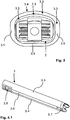
- a cup 2 has been found to be suitable, as is exemplified in FIG Fig. 2 is shown in perspective.
- Such a basket has a stable outer frame 2.1 and an inner porous, lattice-like or reticulated structure 2.2, which allows the bones of the adjacent vertebrae 1.1, 1.2 to grow into this structure in order to create a firm connection.
- the cup tapers in the longitudinal direction towards its distal end.
- the upper surface 2.3 is convexly curved over the width with a relatively large radius of curvature. This enables the relative position of the vertebrae to be adjusted across the cup 2.
- the lower surface of the cup is the (in Fig. 2 (not visible) lower surface of the basket, as well as the side walls over their width or height are not curved, but at least almost flat.
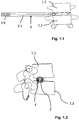
- Such an intervertebral cup 2 is like this Fig. 1.1 to 1.3 can be removed, inserted through a guide sleeve 3 into the intervertebral area or the former intervertebral disc space.
- the guide sleeve 3 has a non-cylindrical jacket 3.1 and an (inner) lumen 3.2 with a non-cylindrical constant lumen cross-section over its entire length.
- the cross-sectional contour of the lumen 3.2 of the guide sleeve 3 is aligned with the maximum cross-sectional contour of the intervertebral cage 2 to be introduced ( Fig. 2 ), that is, its cross-sectional contour is adapted with sufficient tolerance shortly before the proximal end of the basket 2.
- the jacket 3.1 or the wall of the guide sleeve 3 essentially has opposing upper and lower broad sides 3.3, 3.4 and connecting narrow sides 3.5, 3.6, in the present embodiment two opposing narrow sides 3.5, 3.6.
- the lower broad side 3.4 like the narrow sides 3.5, 3.6, is essentially flat on the inside towards the lumen, the transition between the broad side 3.4 and the narrow sides 3.5, 3.6 not being sharp angled, but rounded - the radius of curvature of the transition between lower broad side 3.4 and narrow sides 3.5, 3.6 is 4 mm here.
- the upper broad side 3.3 is formed convexly curved outwards over the width of the guide sleeve 3 (ie not flat).
- the radius of curvature of the upper broad side is 12 mm here.
- the sleeve points on its proximal outside Transverse grooves 3.8 and diametrically opposite wall openings 3.9. The design improves the grip for the surgeon's fingers or tools.
- the wall thickness of the upper and lower broad sides 3.3, 3.4 is less than the wall thickness of the narrow sides 3.5, 3.6. While the wall thickness of the upper and lower broad sides 3.3, 3.4 is typically approx. 1 mm in the exemplary embodiment shown, the wall thickness of the narrow sides 3.5, 3.6 is approx. 1.5 mm (the illustration in FIG Fig. 3 is an enlarged view). At the distal end of the narrow sides 3.5, 3.6 - distal - projections 3.7 are formed ( Fig. 1 , 4.1 to 4.2 ).
- Intervertebral cage 2 and guide sleeve 3 together form a set for spinal surgery.
- Their cross-sectional contour, the outer of the cup 2 and that of the lumen of the guide sleeve 3, are matched to one another.
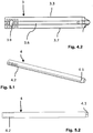
- the Fig. 5 .'1 and 5.2 show a dilator 4, which comes to lie directly within the guide sleeve 3 when this is pushed over him.
- the outer contour of the dilator 4 located directly inside the guide sleeve 3 is accordingly adapted to the lumen of the guide sleeve 3 with small tolerances. That is, the lower outer broad side of the dilator, like the outer narrow sides thereof, is largely flat, while the upper outer broad side is convexly curved outwards.
- the outer cross-sectional contour of the dilator 4 is constant over most of its length; only the distal end 4.1 of the dilator 4 tapers conically, as is usual with such dilators.
- the inner lumen of the dilator 4 is, as in FIG fig. 5.1 in particular at the right - distal - end of the dilator 4 in the, or also at the left - proximal - end in the Fig. 6.3 can be seen, cylindrical, so the proximal and distal inlet and outlet openings are circular.
- the dilator 4 also has transverse grooves 4.2 on its proximal outside.
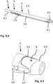
- Fig. 6.1 to 6.5 show an (introductory) set for a spinal surgery with a guide sleeve as described above and two illustrated dilators that have been described above in particular with reference to FIG ig. 5.1 and 5.2 described dilator 4 and a further dilator 5, which comes to lie within the dilator 4 or on which the dilator 4 is pushed.
- the other in the Fig. 6.1 to 6.5 The dilator 5 shown - further inside - has a cylindrical outer contour - and also a cylindrical inner contour - corresponding to the cylindrical inner contour of the dilator 4, as is usual with such dilators.
- the Both individual sets from parts 2, 3 on the one hand and 3, 4, 5 on the other hand form an entire operation set.
- both posterior-lateral P and anterior-lateral A preferably with an access angle of 30 ° to 60 °, preferably 40 ° to 50 ° in each case to the - middle - sagittal plane S or in this lying - horizontal - sagittal axis in each case at the top from the side, back and front, as shown in FIG Fig. 7 is shown.
- the posterior-lateral access can preferably take place along the outer side surface of the spinous process 1.3 of the vertebra 1.1.
- the non-cylindrical design of the guide sleeve according to the invention ensures that, on the one hand, an intervertebral basket can be inserted through it, but on the other hand, the tissue stress of a patient in the insertion area of the guide sleeve 3 between the skin surface and the intervertebral area, in particular in the direction of the extension of the spine, is loaded as little as possible, since the inventive design of the guide sleeve, its height can be significantly reduced compared to conventional cylindrical guide sleeves (with circular cross-section).
Applications Claiming Priority (2)
| Application Number | Priority Date | Filing Date | Title |
|---|---|---|---|
| DE102015012171.5A DE102015012171A1 (de) | 2015-09-23 | 2015-09-23 | Führungshülse und Sets mit Führungshülse für Wirbelsäuleneingriffe |
| PCT/EP2016/001342 WO2017050410A1 (de) | 2015-09-23 | 2016-08-04 | Vorrichtung für wirbelsäuleneingriffe, zugehörige führungshülse und set mit führungshülse |
Publications (2)
| Publication Number | Publication Date |
|---|---|
| EP3352709A1 EP3352709A1 (de) | 2018-08-01 |
| EP3352709B1 true EP3352709B1 (de) | 2021-09-29 |
Family
ID=56694083
Family Applications (1)
| Application Number | Title | Priority Date | Filing Date |
|---|---|---|---|
| EP16753246.4A Active EP3352709B1 (de) | 2015-09-23 | 2016-08-04 | Vorrichtung für wirbelsäuleneingriffe, zugehörige führungshülse und set mit führungshülse |
Country Status (8)
| Country | Link |
|---|---|
| US (1) | US10390968B2 (ja) |
| EP (1) | EP3352709B1 (ja) |
| JP (1) | JP6845583B2 (ja) |
| KR (1) | KR20180056644A (ja) |
| CN (1) | CN108135708B (ja) |
| DE (1) | DE102015012171A1 (ja) |
| ES (1) | ES2898549T3 (ja) |
| WO (1) | WO2017050410A1 (ja) |
Families Citing this family (1)
| Publication number | Priority date | Publication date | Assignee | Title |
|---|---|---|---|---|
| KR102365883B1 (ko) * | 2020-07-07 | 2022-02-23 | 김현성 | 척추내시경 수술용 보형물 삽입 가이드 장치 |
Family Cites Families (14)
| Publication number | Priority date | Publication date | Assignee | Title |
|---|---|---|---|---|
| CA2327501A1 (en) * | 1998-04-09 | 1999-10-21 | Sdgi Holdings, Inc. | Method and instrumentation for vertebral interbody fusion |
| ES2223801T3 (es) | 2000-02-22 | 2005-03-01 | Sdgi Holdings, Inc. | Instrumentos que sirven para preparar un espacio discal. |
| FR2836373B1 (fr) * | 2002-02-26 | 2005-03-25 | Materiel Orthopedique En Abreg | Implants intersomatiques connectables pour l'insertion d'un greffon osseux pour la realisation d'une fusion intervertebrale, instruments pour la connexion de ces implants |
| US7083625B2 (en) * | 2002-06-28 | 2006-08-01 | Sdgi Holdings, Inc. | Instruments and techniques for spinal disc space preparation |
| US7727279B2 (en) * | 2005-06-03 | 2010-06-01 | Zipnick Richard I | Minimally invasive apparatus to manipulate and revitalize spinal column disc |
| US20120143341A1 (en) * | 2006-12-12 | 2012-06-07 | Arthrodisc, L.L.C. | Devices and methods for visual differentiation of intervertebral spaces |
| US8025664B2 (en) * | 2006-11-03 | 2011-09-27 | Innovative Spine, Llc | System and method for providing surgical access to a spine |
| JP5271281B2 (ja) * | 2007-02-09 | 2013-08-21 | アルファテック スパイン, インコーポレイテッド | 曲線状脊椎アクセス方法およびデバイス |
| US9211140B2 (en) * | 2010-11-24 | 2015-12-15 | Kyphon Sarl | Dynamically expandable cannulae and systems and methods for performing percutaneous surgical procedures employing same |
| US8518087B2 (en) * | 2011-03-10 | 2013-08-27 | Interventional Spine, Inc. | Method and apparatus for minimally invasive insertion of intervertebral implants |
| US8394129B2 (en) * | 2011-03-10 | 2013-03-12 | Interventional Spine, Inc. | Method and apparatus for minimally invasive insertion of intervertebral implants |
| US9119732B2 (en) | 2013-03-15 | 2015-09-01 | Orthocision, Inc. | Method and implant system for sacroiliac joint fixation and fusion |
| DE102013004964B4 (de) | 2013-03-22 | 2016-11-03 | Joimax Gmbh | Instrumentenset und Verfahren zum Einbringen eines Körbchens in das Bandscheibenfach zwischen zwei Wirbelkörpern |
| DE202014003441U1 (de) * | 2013-08-14 | 2014-11-18 | Joimax Gmbh | Zwischenwirbel-Körbchen |
-
2015
- 2015-09-23 DE DE102015012171.5A patent/DE102015012171A1/de not_active Withdrawn
-
2016
- 2016-08-04 KR KR1020187007050A patent/KR20180056644A/ko not_active Application Discontinuation
- 2016-08-04 WO PCT/EP2016/001342 patent/WO2017050410A1/de unknown
- 2016-08-04 ES ES16753246T patent/ES2898549T3/es active Active
- 2016-08-04 EP EP16753246.4A patent/EP3352709B1/de active Active
- 2016-08-04 JP JP2018508211A patent/JP6845583B2/ja active Active
- 2016-08-04 US US15/761,625 patent/US10390968B2/en active Active
- 2016-08-04 CN CN201680055219.9A patent/CN108135708B/zh active Active
Also Published As
| Publication number | Publication date |
|---|---|
| EP3352709A1 (de) | 2018-08-01 |
| ES2898549T3 (es) | 2022-03-07 |
| WO2017050410A1 (de) | 2017-03-30 |
| CN108135708B (zh) | 2020-11-03 |
| US10390968B2 (en) | 2019-08-27 |
| DE102015012171A1 (de) | 2017-03-23 |
| KR20180056644A (ko) | 2018-05-29 |
| US20180344480A1 (en) | 2018-12-06 |
| JP2018527986A (ja) | 2018-09-27 |
| CN108135708A (zh) | 2018-06-08 |
| JP6845583B2 (ja) | 2021-03-17 |
Similar Documents
| Publication | Publication Date | Title |
|---|---|---|
| DE69926523T2 (de) | Instrument für die rückgratchirurgie | |
| EP2976046B1 (de) | Instrumentenset zum einbringen eines körbchens in das bandscheibenfach zwischen zwei wirbelkörpern | |
| DE69633778T2 (de) | Instrumentarium zur chirurgischen korrektur der menschlichen wirbelsäule in lenden- und brusthöhe | |
| DE60310241T2 (de) | Ovaler dilator und retraktor | |
| EP3954312B1 (de) | Chirurgisches instrumtent | |
| EP2096982B1 (de) | Vorrichtung und verfahren zum minimal-invasiven eingriff an der wirbelsäule | |
| DE60129361T2 (de) | Hülse für ein laparoskopisches Instrument | |
| DE10027988C2 (de) | Vorrichtung zur stereotaktisch geführten perkutanen Implantation der Längsverbindung der Pedikelschrauben | |
| DE69920178T2 (de) | Super-elastische gebogene hohlnadel zur medizinischen verwendung | |
| DE10125717A1 (de) | Manipulator zur Handhabung einer Pedikelschraube | |
| EP2497433B1 (de) | Mehrfachtrokarsystem | |
| EP2640289B1 (de) | Vorrichtung zum verbinden knöchener strukturen | |
| EP0918489B1 (de) | Trokarhülse für die endoskopie | |
| EP3352709B1 (de) | Vorrichtung für wirbelsäuleneingriffe, zugehörige führungshülse und set mit führungshülse | |
| DE10003051C2 (de) | Instrumentarium für die Lendenwirbelsäulenchirurgie | |
| EP3641670B1 (de) | Instrumenten-set für wirbelsäulenoperationen | |
| DE202013007340U1 (de) | Operationsset zum Legen eines Zugangsrohrs in die Bandscheibe eines Patienten | |
| WO2013120477A2 (de) | Chirurgischer clip und vorrichtung zum applizieren des clips | |
| DE202021105388U1 (de) | Endoskopisches Instrumentarium für die Bandscheibenchirurgie | |
| EP3484386B1 (de) | Vorrichtung zum zugang in das innere eines körpers | |
| DE10309986B4 (de) | Implantat, Implantatsystem zum Wiederaufbau eines Wirbelkörpers | |
| DE19959975A1 (de) | Kanüle und Instrumentenset | |
| DE102005027866B4 (de) | Medizinisches Instrument für Operationen im Bereich einer Wirbelsäule | |
| DE202023102725U1 (de) | Abgestufter Halbzahnhalter | |
| DE3712869A1 (de) | Kanuele zum rueckenmarksnahen einfuehren eines katheters |
Legal Events
| Date | Code | Title | Description |
|---|---|---|---|
| STAA | Information on the status of an ep patent application or granted ep patent |
Free format text: STATUS: THE INTERNATIONAL PUBLICATION HAS BEEN MADE |
|
| PUAI | Public reference made under article 153(3) epc to a published international application that has entered the european phase |
Free format text: ORIGINAL CODE: 0009012 |
|
| STAA | Information on the status of an ep patent application or granted ep patent |
Free format text: STATUS: REQUEST FOR EXAMINATION WAS MADE |
|
| 17P | Request for examination filed |
Effective date: 20180214 |
|
| AK | Designated contracting states |
Kind code of ref document: A1 Designated state(s): AL AT BE BG CH CY CZ DE DK EE ES FI FR GB GR HR HU IE IS IT LI LT LU LV MC MK MT NL NO PL PT RO RS SE SI SK SM TR |
|
| AX | Request for extension of the european patent |
Extension state: BA ME |
|
| DAV | Request for validation of the european patent (deleted) | ||
| DAX | Request for extension of the european patent (deleted) | ||
| STAA | Information on the status of an ep patent application or granted ep patent |
Free format text: STATUS: EXAMINATION IS IN PROGRESS |
|
| 17Q | First examination report despatched |
Effective date: 20201116 |
|
| STAA | Information on the status of an ep patent application or granted ep patent |
Free format text: STATUS: EXAMINATION IS IN PROGRESS |
|
| REG | Reference to a national code |
Ref country code: DE Ref legal event code: R079 Ref document number: 502016013920 Country of ref document: DE Free format text: PREVIOUS MAIN CLASS: A61F0002440000 Ipc: A61F0002300000 |
|
| GRAP | Despatch of communication of intention to grant a patent |
Free format text: ORIGINAL CODE: EPIDOSNIGR1 |
|
| STAA | Information on the status of an ep patent application or granted ep patent |
Free format text: STATUS: GRANT OF PATENT IS INTENDED |
|
| RIC1 | Information provided on ipc code assigned before grant |
Ipc: A61B 17/02 20060101ALI20210326BHEP Ipc: A61F 2/46 20060101ALI20210326BHEP Ipc: A61F 2/44 20060101ALI20210326BHEP Ipc: A61F 2/30 20060101AFI20210326BHEP |
|
| INTG | Intention to grant announced |
Effective date: 20210430 |
|
| GRAS | Grant fee paid |
Free format text: ORIGINAL CODE: EPIDOSNIGR3 |
|
| GRAA | (expected) grant |
Free format text: ORIGINAL CODE: 0009210 |
|
| STAA | Information on the status of an ep patent application or granted ep patent |
Free format text: STATUS: THE PATENT HAS BEEN GRANTED |
|
| AK | Designated contracting states |
Kind code of ref document: B1 Designated state(s): AL AT BE BG CH CY CZ DE DK EE ES FI FR GB GR HR HU IE IS IT LI LT LU LV MC MK MT NL NO PL PT RO RS SE SI SK SM TR |
|
| REG | Reference to a national code |
Ref country code: GB Ref legal event code: FG4D Free format text: NOT ENGLISH |
|
| REG | Reference to a national code |
Ref country code: CH Ref legal event code: EP Ref country code: AT Ref legal event code: REF Ref document number: 1433551 Country of ref document: AT Kind code of ref document: T Effective date: 20211015 |
|
| REG | Reference to a national code |
Ref country code: DE Ref legal event code: R096 Ref document number: 502016013920 Country of ref document: DE |
|
| REG | Reference to a national code |
Ref country code: IE Ref legal event code: FG4D Free format text: LANGUAGE OF EP DOCUMENT: GERMAN |
|
| REG | Reference to a national code |
Ref country code: NL Ref legal event code: FP |
|
| REG | Reference to a national code |
Ref country code: SE Ref legal event code: TRGR |
|
| REG | Reference to a national code |
Ref country code: LT Ref legal event code: MG9D |
|
| PG25 | Lapsed in a contracting state [announced via postgrant information from national office to epo] |
Ref country code: RS Free format text: LAPSE BECAUSE OF FAILURE TO SUBMIT A TRANSLATION OF THE DESCRIPTION OR TO PAY THE FEE WITHIN THE PRESCRIBED TIME-LIMIT Effective date: 20210929 Ref country code: NO Free format text: LAPSE BECAUSE OF FAILURE TO SUBMIT A TRANSLATION OF THE DESCRIPTION OR TO PAY THE FEE WITHIN THE PRESCRIBED TIME-LIMIT Effective date: 20211229 Ref country code: FI Free format text: LAPSE BECAUSE OF FAILURE TO SUBMIT A TRANSLATION OF THE DESCRIPTION OR TO PAY THE FEE WITHIN THE PRESCRIBED TIME-LIMIT Effective date: 20210929 Ref country code: HR Free format text: LAPSE BECAUSE OF FAILURE TO SUBMIT A TRANSLATION OF THE DESCRIPTION OR TO PAY THE FEE WITHIN THE PRESCRIBED TIME-LIMIT Effective date: 20210929 Ref country code: BG Free format text: LAPSE BECAUSE OF FAILURE TO SUBMIT A TRANSLATION OF THE DESCRIPTION OR TO PAY THE FEE WITHIN THE PRESCRIBED TIME-LIMIT Effective date: 20211229 Ref country code: LT Free format text: LAPSE BECAUSE OF FAILURE TO SUBMIT A TRANSLATION OF THE DESCRIPTION OR TO PAY THE FEE WITHIN THE PRESCRIBED TIME-LIMIT Effective date: 20210929 |
|
| PG25 | Lapsed in a contracting state [announced via postgrant information from national office to epo] |
Ref country code: LV Free format text: LAPSE BECAUSE OF FAILURE TO SUBMIT A TRANSLATION OF THE DESCRIPTION OR TO PAY THE FEE WITHIN THE PRESCRIBED TIME-LIMIT Effective date: 20210929 Ref country code: GR Free format text: LAPSE BECAUSE OF FAILURE TO SUBMIT A TRANSLATION OF THE DESCRIPTION OR TO PAY THE FEE WITHIN THE PRESCRIBED TIME-LIMIT Effective date: 20211230 |
|
| REG | Reference to a national code |
Ref country code: ES Ref legal event code: FG2A Ref document number: 2898549 Country of ref document: ES Kind code of ref document: T3 Effective date: 20220307 |
|
| PG25 | Lapsed in a contracting state [announced via postgrant information from national office to epo] |
Ref country code: IS Free format text: LAPSE BECAUSE OF FAILURE TO SUBMIT A TRANSLATION OF THE DESCRIPTION OR TO PAY THE FEE WITHIN THE PRESCRIBED TIME-LIMIT Effective date: 20220129 Ref country code: SK Free format text: LAPSE BECAUSE OF FAILURE TO SUBMIT A TRANSLATION OF THE DESCRIPTION OR TO PAY THE FEE WITHIN THE PRESCRIBED TIME-LIMIT Effective date: 20210929 Ref country code: RO Free format text: LAPSE BECAUSE OF FAILURE TO SUBMIT A TRANSLATION OF THE DESCRIPTION OR TO PAY THE FEE WITHIN THE PRESCRIBED TIME-LIMIT Effective date: 20210929 Ref country code: PT Free format text: LAPSE BECAUSE OF FAILURE TO SUBMIT A TRANSLATION OF THE DESCRIPTION OR TO PAY THE FEE WITHIN THE PRESCRIBED TIME-LIMIT Effective date: 20220131 Ref country code: PL Free format text: LAPSE BECAUSE OF FAILURE TO SUBMIT A TRANSLATION OF THE DESCRIPTION OR TO PAY THE FEE WITHIN THE PRESCRIBED TIME-LIMIT Effective date: 20210929 Ref country code: EE Free format text: LAPSE BECAUSE OF FAILURE TO SUBMIT A TRANSLATION OF THE DESCRIPTION OR TO PAY THE FEE WITHIN THE PRESCRIBED TIME-LIMIT Effective date: 20210929 Ref country code: CZ Free format text: LAPSE BECAUSE OF FAILURE TO SUBMIT A TRANSLATION OF THE DESCRIPTION OR TO PAY THE FEE WITHIN THE PRESCRIBED TIME-LIMIT Effective date: 20210929 Ref country code: AL Free format text: LAPSE BECAUSE OF FAILURE TO SUBMIT A TRANSLATION OF THE DESCRIPTION OR TO PAY THE FEE WITHIN THE PRESCRIBED TIME-LIMIT Effective date: 20210929 |
|
| REG | Reference to a national code |
Ref country code: DE Ref legal event code: R097 Ref document number: 502016013920 Country of ref document: DE |
|
| PG25 | Lapsed in a contracting state [announced via postgrant information from national office to epo] |
Ref country code: DK Free format text: LAPSE BECAUSE OF FAILURE TO SUBMIT A TRANSLATION OF THE DESCRIPTION OR TO PAY THE FEE WITHIN THE PRESCRIBED TIME-LIMIT Effective date: 20210929 |
|
| PLBE | No opposition filed within time limit |
Free format text: ORIGINAL CODE: 0009261 |
|
| STAA | Information on the status of an ep patent application or granted ep patent |
Free format text: STATUS: NO OPPOSITION FILED WITHIN TIME LIMIT |
|
| 26N | No opposition filed |
Effective date: 20220630 |
|
| PG25 | Lapsed in a contracting state [announced via postgrant information from national office to epo] |
Ref country code: SI Free format text: LAPSE BECAUSE OF FAILURE TO SUBMIT A TRANSLATION OF THE DESCRIPTION OR TO PAY THE FEE WITHIN THE PRESCRIBED TIME-LIMIT Effective date: 20210929 |
|
| PG25 | Lapsed in a contracting state [announced via postgrant information from national office to epo] |
Ref country code: MC Free format text: LAPSE BECAUSE OF FAILURE TO SUBMIT A TRANSLATION OF THE DESCRIPTION OR TO PAY THE FEE WITHIN THE PRESCRIBED TIME-LIMIT Effective date: 20210929 |
|
| PG25 | Lapsed in a contracting state [announced via postgrant information from national office to epo] |
Ref country code: LU Free format text: LAPSE BECAUSE OF NON-PAYMENT OF DUE FEES Effective date: 20220804 |
|
| PG25 | Lapsed in a contracting state [announced via postgrant information from national office to epo] |
Ref country code: IE Free format text: LAPSE BECAUSE OF NON-PAYMENT OF DUE FEES Effective date: 20220804 |
|
| PGFP | Annual fee paid to national office [announced via postgrant information from national office to epo] |
Ref country code: NL Payment date: 20230823 Year of fee payment: 8 |
|
| PGFP | Annual fee paid to national office [announced via postgrant information from national office to epo] |
Ref country code: TR Payment date: 20230731 Year of fee payment: 8 Ref country code: IT Payment date: 20230831 Year of fee payment: 8 Ref country code: GB Payment date: 20230824 Year of fee payment: 8 Ref country code: ES Payment date: 20230918 Year of fee payment: 8 Ref country code: CH Payment date: 20230902 Year of fee payment: 8 Ref country code: AT Payment date: 20230818 Year of fee payment: 8 |
|
| PGFP | Annual fee paid to national office [announced via postgrant information from national office to epo] |
Ref country code: SE Payment date: 20230823 Year of fee payment: 8 Ref country code: FR Payment date: 20230821 Year of fee payment: 8 Ref country code: DE Payment date: 20230809 Year of fee payment: 8 Ref country code: BE Payment date: 20230822 Year of fee payment: 8 |
|
| PG25 | Lapsed in a contracting state [announced via postgrant information from national office to epo] |
Ref country code: HU Free format text: LAPSE BECAUSE OF FAILURE TO SUBMIT A TRANSLATION OF THE DESCRIPTION OR TO PAY THE FEE WITHIN THE PRESCRIBED TIME-LIMIT; INVALID AB INITIO Effective date: 20160804 |
|
| PG25 | Lapsed in a contracting state [announced via postgrant information from national office to epo] |
Ref country code: SM Free format text: LAPSE BECAUSE OF FAILURE TO SUBMIT A TRANSLATION OF THE DESCRIPTION OR TO PAY THE FEE WITHIN THE PRESCRIBED TIME-LIMIT Effective date: 20210929 Ref country code: MK Free format text: LAPSE BECAUSE OF FAILURE TO SUBMIT A TRANSLATION OF THE DESCRIPTION OR TO PAY THE FEE WITHIN THE PRESCRIBED TIME-LIMIT Effective date: 20210929 Ref country code: CY Free format text: LAPSE BECAUSE OF FAILURE TO SUBMIT A TRANSLATION OF THE DESCRIPTION OR TO PAY THE FEE WITHIN THE PRESCRIBED TIME-LIMIT Effective date: 20210929 |