EP3350665B1 - Biegbare vorrichtung mit einer anzeige in beweglicher verbindung mit dem körper - Google Patents
Biegbare vorrichtung mit einer anzeige in beweglicher verbindung mit dem körper Download PDFInfo
- Publication number
- EP3350665B1 EP3350665B1 EP16753531.9A EP16753531A EP3350665B1 EP 3350665 B1 EP3350665 B1 EP 3350665B1 EP 16753531 A EP16753531 A EP 16753531A EP 3350665 B1 EP3350665 B1 EP 3350665B1
- Authority
- EP
- European Patent Office
- Prior art keywords
- supporting layer
- electronic device
- display stack
- bendable
- display
- Prior art date
- Legal status (The legal status is an assumption and is not a legal conclusion. Google has not performed a legal analysis and makes no representation as to the accuracy of the status listed.)
- Active
Links
Images


Classifications
-
- G—PHYSICS
- G06—COMPUTING OR CALCULATING; COUNTING
- G06F—ELECTRIC DIGITAL DATA PROCESSING
- G06F3/00—Input arrangements for transferring data to be processed into a form capable of being handled by the computer; Output arrangements for transferring data from processing unit to output unit, e.g. interface arrangements
- G06F3/01—Input arrangements or combined input and output arrangements for interaction between user and computer
- G06F3/03—Arrangements for converting the position or the displacement of a member into a coded form
- G06F3/041—Digitisers, e.g. for touch screens or touch pads, characterised by the transducing means
- G06F3/0412—Digitisers structurally integrated in a display
-
- G—PHYSICS
- G06—COMPUTING OR CALCULATING; COUNTING
- G06F—ELECTRIC DIGITAL DATA PROCESSING
- G06F1/00—Details not covered by groups G06F3/00 - G06F13/00 and G06F21/00
- G06F1/16—Constructional details or arrangements
- G06F1/1613—Constructional details or arrangements for portable computers
- G06F1/1633—Constructional details or arrangements of portable computers not specific to the type of enclosures covered by groups G06F1/1615 - G06F1/1626
- G06F1/1637—Details related to the display arrangement, including those related to the mounting of the display in the housing
- G06F1/1652—Details related to the display arrangement, including those related to the mounting of the display in the housing the display being flexible, e.g. mimicking a sheet of paper, or rollable
-
- G—PHYSICS
- G09—EDUCATION; CRYPTOGRAPHY; DISPLAY; ADVERTISING; SEALS
- G09G—ARRANGEMENTS OR CIRCUITS FOR CONTROL OF INDICATING DEVICES USING STATIC MEANS TO PRESENT VARIABLE INFORMATION
- G09G3/00—Control arrangements or circuits, of interest only in connection with visual indicators other than cathode-ray tubes
- G09G3/20—Control arrangements or circuits, of interest only in connection with visual indicators other than cathode-ray tubes for presentation of an assembly of a number of characters, e.g. a page, by composing the assembly by combination of individual elements arranged in a matrix no fixed position being assigned to or needed to be assigned to the individual characters or partial characters
- G09G3/22—Control arrangements or circuits, of interest only in connection with visual indicators other than cathode-ray tubes for presentation of an assembly of a number of characters, e.g. a page, by composing the assembly by combination of individual elements arranged in a matrix no fixed position being assigned to or needed to be assigned to the individual characters or partial characters using controlled light sources
- G09G3/30—Control arrangements or circuits, of interest only in connection with visual indicators other than cathode-ray tubes for presentation of an assembly of a number of characters, e.g. a page, by composing the assembly by combination of individual elements arranged in a matrix no fixed position being assigned to or needed to be assigned to the individual characters or partial characters using controlled light sources using electroluminescent panels
- G09G3/32—Control arrangements or circuits, of interest only in connection with visual indicators other than cathode-ray tubes for presentation of an assembly of a number of characters, e.g. a page, by composing the assembly by combination of individual elements arranged in a matrix no fixed position being assigned to or needed to be assigned to the individual characters or partial characters using controlled light sources using electroluminescent panels semiconductive, e.g. using light-emitting diodes [LED]
- G09G3/3208—Control arrangements or circuits, of interest only in connection with visual indicators other than cathode-ray tubes for presentation of an assembly of a number of characters, e.g. a page, by composing the assembly by combination of individual elements arranged in a matrix no fixed position being assigned to or needed to be assigned to the individual characters or partial characters using controlled light sources using electroluminescent panels semiconductive, e.g. using light-emitting diodes [LED] organic, e.g. using organic light-emitting diodes [OLED]
- G09G3/3225—Control arrangements or circuits, of interest only in connection with visual indicators other than cathode-ray tubes for presentation of an assembly of a number of characters, e.g. a page, by composing the assembly by combination of individual elements arranged in a matrix no fixed position being assigned to or needed to be assigned to the individual characters or partial characters using controlled light sources using electroluminescent panels semiconductive, e.g. using light-emitting diodes [LED] organic, e.g. using organic light-emitting diodes [OLED] using an active matrix
-
- H—ELECTRICITY
- H04—ELECTRIC COMMUNICATION TECHNIQUE
- H04M—TELEPHONIC COMMUNICATION
- H04M1/00—Substation equipment, e.g. for use by subscribers
- H04M1/02—Constructional features of telephone sets
- H04M1/0202—Portable telephone sets, e.g. cordless phones, mobile phones or bar type handsets
- H04M1/026—Details of the structure or mounting of specific components
- H04M1/0266—Details of the structure or mounting of specific components for a display module assembly
- H04M1/0268—Details of the structure or mounting of specific components for a display module assembly including a flexible display panel
-
- G—PHYSICS
- G06—COMPUTING OR CALCULATING; COUNTING
- G06F—ELECTRIC DIGITAL DATA PROCESSING
- G06F1/00—Details not covered by groups G06F3/00 - G06F13/00 and G06F21/00
- G06F1/16—Constructional details or arrangements
- G06F1/1613—Constructional details or arrangements for portable computers
- G06F1/1615—Constructional details or arrangements for portable computers with several enclosures having relative motions, each enclosure supporting at least one I/O or computing function
- G06F1/1616—Constructional details or arrangements for portable computers with several enclosures having relative motions, each enclosure supporting at least one I/O or computing function with folding flat displays, e.g. laptop computers or notebooks having a clamshell configuration, with body parts pivoting to an open position around an axis parallel to the plane they define in closed position
-
- G—PHYSICS
- G06—COMPUTING OR CALCULATING; COUNTING
- G06F—ELECTRIC DIGITAL DATA PROCESSING
- G06F2203/00—Indexing scheme relating to G06F3/00 - G06F3/048
- G06F2203/041—Indexing scheme relating to G06F3/041 - G06F3/045
- G06F2203/04102—Flexible digitiser, i.e. constructional details for allowing the whole digitising part of a device to be flexed or rolled like a sheet of paper
-
- G—PHYSICS
- G06—COMPUTING OR CALCULATING; COUNTING
- G06F—ELECTRIC DIGITAL DATA PROCESSING
- G06F2203/00—Indexing scheme relating to G06F3/00 - G06F3/048
- G06F2203/041—Indexing scheme relating to G06F3/041 - G06F3/045
- G06F2203/04103—Manufacturing, i.e. details related to manufacturing processes specially suited for touch sensitive devices
Definitions
- EP 2765479 discloses a folding portion configured to bend at one end of a body of the flexible portable terminal in a direction to a front surface or a rear surface of the flexible portable terminal, a flexible display unit configured to be mounted on the body of the flexible portable terminal, and to bend in the front surface or the rear surface of the flexible portable terminal according to a bending direction of the folding portion, and a sliding portion configured to enable one end of the flexible display unit to slide according to a difference of a compression/tension caused by a difference of an elongation between the folding portion and the flexible display unit when the folding portion is bent.
- EP 2728433 discloses housing (116) for a flexible display panel (22) having a first component (118) and a second component (120) coupled to one another by a pivot member (122) and movable relative to one another between an open position in which the first component (118) and the second component (120) are in the same plane and a folded position; a first slider slidably (138) received in the first component (118) and a second slider (140) slidably received in the second component (140), the first slider (138) and the second slider (140) being movable toward the pivot member (122) when the first component and the second component move from the open position to the folded position; and a flexible membrane (22) coupled to the first slider (138), the second slider (140) and the pivot member 122; wherein, in the folded position, the flexible membrane (22) is located between the first component (118) and the second component (120).
- the foldable display apparatus includes a flexible display panel, first body configured to support a left portion of a flexible display panel, and second body configured to support a right portion of the flexible display panel, first and second frames configured to surround portions of outlines of the first and second bodies, a hinge member configured to hinge-connect the first and second frames with each other in a foldable manner, and first and second supports having sides hinge-connected to the first and second frames, and configured to form an accommodation space in which a folded portion of the flexible display panel is folded to form a curvature at a first position at which the first and second bodies are folded, and to support the folded portion of the flexible display panel at a second position at which the first and second bodies are unfolded.
- the foldable display apparatus can include a display panel configured to include a display area which includes a first display area, a second display area, and a bending area which is defined between the first and second display areas, a housing configured to include a first housing member, which supports a first area of the display panel corresponding to the first display area, and a second housing member which supports a second area of the display panel corresponding to the second display area, and a hinge part connected between the first and second housing members, and configured to enable the display panel to be folded or unfolded with respect to the bending area.
- the electronic device comprises a body and a flexible display stack.
- the display stack and the body are in a movable connection via fastening areas and fastening components.
- the fastening areas and components include magnets.
- the methods disclosed relate to the way the display stack is fixed to the body, via magnets brought in proximity to each other and via studs locking into grooves.
- the aspects described below are not limited to implementations which solve any or all of the disadvantages of known devices and covers.
- the present examples are described and illustrated herein as being implemented with a stack of few layers connected to a body, the devices described are provided as an example and not a limitation.
- the presented aspects are suitable for application in a variety of bendable devices comprising multiple stacks of layers, and the individual elements can be a schematic representation of various parts of a device, such as a display or a touch screen. These parts may comprise a plurality of different layers and other elements in between the body and the display stack.
- the display part of the device has to be attached to the main body in a way that does not prevent or resist bending of the device.
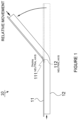
- FIG. 1 is a schematic illustration of a bendable device 10 which comprises a display stack 11 and a body 12.
- the device 10 may be, but is not limited to, a bendable electronic device, a bendable handheld electronic device or a foldable electronic device. Structural features of devices according to aspects are described in more detail with reference to Figures 2 - 5B ; and the side view of FIG. 1 serves to illustrate the mechanism of relative movement that occurs when the device 10 is bent.
- the display stack 11 is movably fixed to the body 12
- movement of the display stack 11 occurs relative to the body 12 similar to relative movement of pages of a stack of papers when bent. This movement occurs due to different neutral axes for the stack 11 and body 12.
- a neutral axis of bending is the axis where no compression or extension occurs, and it is usually lies inside the structure that is being bent. Unless the stack 11 and the body 12 are in a rigid connection along the whole surface, they bend as two individual structures.
- the first neutral axis 111 of the flexible display stack normally lies above the second neutral axis 112 of the body 12, which leads to their relative movement. This relative movement is present in aspects described below which provide a movable connection between at least parts of the display stack 11 and the body 12.
- the approximate neutral axis 111 and possible bending direction are shown in FIG. 2 by dashed lines and arrows.
- FIG. 2 shows a bendable device 10 according to an aspect.
- the device 10 may be, but is not limited to, a bendable electronic device, a bendable handheld electronic device or a foldable electronic device.
- This Figure is a side cross-section view of the device 10.
- the device 10 comprises a display stack 21 which comprises at least one active layer 212 and a supporting layer 211 on the bottom.
- the display stack 21 may also comprise a window layer 210 on the top. This provides protection of the other layers and the internal parts of the device 10.
- the supporting layer 211 may comprise stainless steel or other metal.
- the supporting layer 211 also has a bending region and comprise rigid material, as discussed in more detail below.
- the device 10 further comprises and a body portion 22 with a bending region 23.
- the bending region 23 may be an extendable hinge, a hinge with rotating elements or any other hinge. A particular type of hinge may be appropriate for the desired type of bending of the device 10.
- the bending region 23 may be an elastic component, for example a rubber component.
- the bending region 23 may have any width or shape. In an aspect, the region 23 may span across the body 22 of the device 10.
- the body 22 may also comprise more than one extendable region 23, for example if the device 10 is bendable about more than one axis.
- the supporting layer 211 comprises one or more fastening areas 221, and the body 22 comprises one or more fastening components 222.
- the fastening components 222 are configured to be operable in a movable connection with the fastening areas 221. They are shown on FIG. 2 only schematically and may have any appropriate shape, size and properties to provide a movable connection.
- the term "movable connection” herein refers to a connection which allows free movement of connected elements in at least one direction within a limited range.
- the above aspects can provide a technical effect of easy bending due to movable connection points, while preventing detachment of the display stack at any point during bending.
- the device 10 is bendable about at least one axis in the bending region 23.
- This axis can be, for example, the axis of a hinge.
- At least one of the fastening components 222 and at least one of the fastening areas 221 are positioned within 2 centimeters from the bending region 23 and opposite to each other. Since the display stack 21 can be likely to detach near the bending region 23, this aspect can have an effect of reliable fastening the stack 21 near the bending region 23.
- the body 22 and the stack 21 are bendable more than 90 degrees. This provides substantially a foldable device.
- the body 22 may optionally comprise a casing 24, as shown in FIG. 2 .
- the casing 24 comprises the bending region 23 of the body 22 and enclose the body 22 and the display stack 21 at least from the bottom and two opposite sides.
- the casing 24 may also include a frame which encloses at least two edges of the stack 21.
- the frame is not shown on the figure but could be, for example, a stripe on the top parts of the casing 24 covering its edges and extending slightly over the window layer 210. This can prevent the stack 21 from moving vertically.
- the casing and the frame comprise metal and/or plastic.
- the terms 'top' and 'bottom' are used for clarity and relate to the positioning on the figures only.
- the bottom supporting layer 212 may be positioned on any geometric side of the device 10.
- Active layers 212 of the display stack 21 may comprise an active display layer and an active touch sensing layer, for example if the device 10 is a bendable touch screen device.
- One of the layers of the display stack 21 may also be a polarizing layer, for example if the display stack is an LCD (Liquid Crystal Display) stack.
- layers of the display stack 21 are fixed to each other and to the window layer 210 by an optically clear adhesive, such as LOCA (liquid optically clear adhesive). Layers of the display stack 21 are thereby laminated to each other with a transparent adhesive.
- the adhesive is schematically illustrated as a dotted filling between layers of the stack 21.
- bendable displays include displays that are 3 mm thin and may operate in a bent form in which the bend radius is 5 cm or less than 1 mm. In the latter bend radius of less than 1 mm, the display may be described as foldable, similar to a folded sheet of paper.
- 'bendable' refers to dynamic bending, and includes both elastic and inelastic plasticity. Aspects of the device 10 can apply to display devices as well as any other devices which include displays.
- the display may be, for example, a flexible organic light emitting diode (OLED) display, an LCD or an electronic paper display.
- OLED organic light emitting diode
- the body 22 of the device 10 may comprise other elements required for operation of the device 10.
- the body 22 of the device may comprise elements such as a controller, a processing unit, and a memory.
- the display stack 21 has an electric connection with the body 22.
- the electric connection can be implemented as a flexible connector, for example via a flexible printed circuit (FPC), to the hardware of the device 10 located in the body 22.
- the connection can be implemented inside the device 10 and made with one of the active layers 210 of the display stack 21.
- the body 22 may have an opening which allows the flexible connector to extend through the opening into the space between the display stack 21 and the body 22, and move without damage or loss of connection inside that space when the device 10 is bent.
- thickness of the display stack may be between 0.1 and 0.5 millimeters.
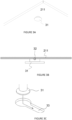
- FIG. 3A is an angled view of the unattached supporting layer 211 with a stud 31 schematically taking place of the fastening area 221 according to an aspect.
- FIG. 3A is an angled view of the unattached supporting layer 211 with a stud 31 schematically taking place of the fastening area 221 according to an aspect.
- FIG. 3B shows a side view of the same, wherein the stud is welded 34 to the supporting layer 211.
- the stud 31 can be made of stainless steel, which in combination with the supporting layer 211 comprising stainless steel provides a possibility to use welding.
- the stud 31 can also be made of any other suitable material, such as metal or plastic.
- FIG. 3C shows the stud 31 which is configured to be inserted into a groove 33 on the body 22.
- the groove 33 is shaped as a keyhole to provide a movable connection with the stud 31.
- the groove 33 may provide a slightly larger space than the radius of the stud 31, allowing the stud 31 slight movement in all horizontal directions.
- fastening areas 221 comprising studs 34 and fastening components 222 comprising grooves 33 may also comprise other fastening elements.
- At least one fastening area 221 of the supporting layer 211 comprises a magnetic element
- at least one fastening component of the body 22 comprises a magnetic element configured to be operable in a movable connection with at least one magnetic element of the supporting layer.
- the magnetic elements may be areas of magnetic material on the supporting layer 211.
- the supporting layer 211 comprises magnetic material at least in the fastening areas 221.
- the supporting layer 211 may also be made of magnetic material. This allows using a thin supporting layer 211.
- the magnetic elements are shown separate from the supporting layer 211 for clarity purposes only. As it is clear to a skilled person, similar implementations are possible wherein the supporting layer 211 comprises magnetic areas which do not extend outside the layer.
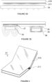
- Figures 3D and 3E illustrate various aspects with magnetic elements mentioned above. These figures are side views of the supporting layer 211 on the bottom of the display stack 21.
- the magnetic elements may comprise neodymium or other rare earth materials, which can provide strong attraction enabling use of small magnets which can be inserted locally.
- the magnetic elements comprise soft rubber and have a prolonged shape. The soft rubber comprising magnetic material can be used on areas of bending.
- FIG. 3D shows a magnetic element 34 as part of the fastening area of the supporting layer 211.
- the magnetic element 34 is shaped as a stripe and may comprise a Halbach array.
- the thickness of the magnetic element 34 is between 0.3 millimeters and 1 millimeter.
- the magnetic field lines are illustrated by dashed lines on the figures.
- FIG. 3E shows a magnetic element 34 as part of the fastening area of the supporting layer 211.
- the stripe 34 may comprise soft rubber and magnetic material. The soft rubber provides increased flexibility and reduced brittleness when the stripe 34 is bent.
- FIG. 3E shows alternative aspects of magnetic elements 34 as part of the fastening area 221 of the supporting layer 211.
- the elements 34 in this aspect can be smaller and have, for example, a round shape.
- the supporting layer 211 on the left part of FIG. 3E comprises a magnetic core.
- the magnetic core can comprise soft iron or other suitable materials.
- the magnetic core can serve to confine the magnetic field and prevent undesired exposure of parts of the device 10, as well as external objects such as credit cards, to said field.
- the magnetic core element 36 can also be attached to the magnet 34 itself, along with an additional magnetic core element 35, as show on the right side of FIG. 3E . When the magnetic field is limited by the magnetic core 36, 37, attraction force can increase since the magnetic field is concentrated into the soft iron.
- magnetic elements 34 are magnets. Magnets can have a strong enough attraction force to keep the display stack 21 attached to the body 22, yet maintain flexibility on the joint and a movable connection.
- the supporting layer 211 of the display stack 21 may comprise a bending region itself, as illustrated on FIG.4 .
- This figure is an angled view of a display stack 21 wherein the active layers together with a window layer 210 are separated from the supporting layer 211, and a hinge is exposed on the supporting layer 211.
- FIG. 5A illustrates an aspect with a possible distribution of fastening components 222 on the body 21, and the fastening areas on the supporting layer 211 (flipped over in relation to the orientation or the body 21 for demonstration purposes). This distribution can be used with studs and magnets.
- FIG. 5B shows two aspects with distributions of magnetic elements 51, 52 across the body 22. This illustrates that the shape, size and positioning of the magnets 51 can vary and be tailored to a particular bending device.
- the circular holes in a magnetic shield 52 can provide reduced weight of the body 22.
- the fastening areas 221 and fastening components 222 comprise gel configured to provide a movable connection.
- the display stack 21 is movably fixed to the body 22 with combination of the above aspects.
- the display stack 21 may also be partially fixed to the body 22 by an adhesive, providing a movable connection only in certain areas of the device 10.
- the adhesive may be used, for example, to connect the display stack 21 to the bending region 23 of the body 21, since the relative movement may not occur around the bending region 23.
- the device 10 may be implemented as a portable electronic device, for example a mobile phone, smart watch, tablet or laptop.
- the above aspects can provide a movable connection of the display stack to the body of an electronic device. This can have a technical effect on its repeatable foldability without buckling or other physical deformations of the display stack. A further effect can be that the device can be resistant to fall damage due to the "floating" connection which can absorb shock. The resulting device can also be easy to disassemble e.g. for maintenance.
- Devices according to any of the above aspects can be used in flexible electronic devices such as mobile phones, tablets, foldable laptop computers, e-readers and other devices.
- the devices may be embedded in or attached to a bendable or foldable electronic system.
- Figure 6 illustrates a method for assembling a bendable electronic device according to an aspect.
- the bendable electronic device may be a bendable display device.
- the method comprises providing 61 a display stack which comprises a supporting layer on the bottom, wherein the supporting layer comprising one or more studs.
- a body which comprises a bending region and keyhole-shaped grooves is then provided at 62.
- the method further comprises movably fixing 63 the display stack to the body by inserting the studs into the grooves.
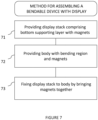
- FIG. 7 illustrates a method for assembling a bendable electronic device according to an aspect.
- the bendable electronic device may be a bendable display device.
- the method comprises providing 71 a display stack which comprises a supporting layer on the bottom, wherein the supporting layer comprising one or more magnetic areas.
- a body which comprises a bending region and magnetic elements is then provided at 72.
- the method further comprises movably fixing 73 the display stack to the body by bringing the magnetic elements into proximity or physical contact with the magnetic areas.
- the magnetic areas comprise separate magnetic elements rigidly attached to the supporting layer.
- the methods described above may have an effect of simplified assembly wherein adhesives are not necessary.
- a further effect is the ease of maintenance, due to the movable connection being more easily removed and then restored; for devices assembled according to the above methods.
- the methods described herein may be performed by software in machine readable form on a tangible storage medium e.g. in the form of a computer program comprising computer program code means adapted to perform all the steps of any of the media include computer storage devices comprising computer-readable media such as disks, thumb drives, memory etc. and do not include propagated signals. Propagated signals may be present in a tangible storage media, but propagated signals per se are not examples of tangible storage media.
- the software can be suitable for execution on a parallel processor or a serial processor such that the method steps may be carried out in any suitable order, or simultaneously.
Landscapes
- Engineering & Computer Science (AREA)
- Theoretical Computer Science (AREA)
- Computer Hardware Design (AREA)
- Physics & Mathematics (AREA)
- General Physics & Mathematics (AREA)
- General Engineering & Computer Science (AREA)
- Human Computer Interaction (AREA)
- Signal Processing (AREA)
- Devices For Indicating Variable Information By Combining Individual Elements (AREA)
Claims (10)
- Elektronische Vorrichtung (10), umfassend:einen Körper (22), umfassend einen ersten Biegebereich (23) einen flexiblen Anzeigestapel (21), umfassend mindestens eine aktive Schicht (212) und eine starre Trägerschicht (211);wobei die starre Trägerschicht (211) an der Unterseite des flexiblen Anzeigestapels (21) angeordnet ist;wobei die starre Trägerschicht (211) des flexiblen Anzeigestapels (21) einen zweiten biegbaren Bereich der Trägerschicht selbst und einen oder mehrere Befestigungsgebiete (221) auf jeder Seite und getrennt von dem zweiten biegbaren Bereich beinhaltet, wobei der zweite biegbare Bereich sich von dem ersten biegbaren Bereich unterscheidet; undder Körper (22) eine oder mehrere Befestigungskomponenten (222) beinhaltet, die in einer beweglichen Verbindung mit jeweiligen Befestigungsgebieten der starren Trägerschicht des flexiblen Anzeigestapels arbeiten, um eine bewegliche Verbindung zwischen dem Körper und der starren Trägerschicht zu bilden;dadurch gekennzeichnet, dass:das eine oder die mehreren Befestigungsgebiete (221) ein oder mehrere erste magnetische Elemente umfassen und die eine oder die mehreren Befestigungskomponenten (222) ein oder mehrere zweite magnetische Elemente zum Zusammenwirken mit dem einen oder den mehreren ersten magnetischen Elementen umfassen undwobei die starre Trägerschicht (211) einen Magnetkern (35) zwischen den magnetischen Elementen und anderen Schichten des flexiblen Anzeigestapels (21) umfasst.
- Elektronische Vorrichtung nach Anspruch 1, wobei der zweite Biegebereich ein Scharnier ist.
- Elektronische Vorrichtung nach Anspruch 1 oder Anspruch 2, wobei die Vorrichtung um mindestens eine Achse in dem ersten Biegebereich (23) biegbar ist.
- Elektronische Vorrichtung nach einem der vorhergehenden Ansprüche, wobei das eine oder die mehreren magnetischen Elemente Neodym umfassen.
- Elektronische Vorrichtung nach einem der vorhergehenden Ansprüche, wobei ein oder mehrere magnetische Elemente Weichgummi umfassen und eine längliche Form aufweisen.
- Elektronische Vorrichtung nach einem der Ansprüche 1 bis 5, wobei:der Körper ein Gehäuse (24) umfasst,das Gehäuse (24) den Biegebereich (23) des Körpers (22) umfasst, unddas Gehäuse (24) den Körper (22) und den Anzeigestapel (21) mindestens von der Unterseite und zwei gegenüberliegenden Seiten her umschließt.
- Elektronische Vorrichtung nach Anspruch 6, wobei das Gehäuse (24) ebenfalls einen Rahmen umfasst, wobei der Rahmen mindestens zwei Kanten des Anzeigestapels (21) umschließt.
- Elektronische Vorrichtung nach einem der Ansprüche 1 bis 7, wobei die starre Trägerschicht (211) Edelstahl umfasst.
- Elektronische Vorrichtung nach einem der Ansprüche 1 bis 8, wobei der flexible Anzeigestapel (21) und der Körper (22) um mehr als 90 Grad biegbar sind.
- Elektronische Vorrichtung nach einem der Ansprüche 1 bis 9, wobei der flexible Anzeigestapel (21) eine aktive organische lichtemittierende Diodenanzeige, eine aktive berührungsempfindliche Schicht und eine Fensterschicht (210) umfasst.
Applications Claiming Priority (2)
| Application Number | Priority Date | Filing Date | Title |
|---|---|---|---|
| US14/855,997 US9778772B2 (en) | 2015-09-16 | 2015-09-16 | Bendable device with display in movable connection with body |
| PCT/US2016/045668 WO2017048398A1 (en) | 2015-09-16 | 2016-08-05 | Bendable device with display in movable connection with body |
Publications (2)
| Publication Number | Publication Date |
|---|---|
| EP3350665A1 EP3350665A1 (de) | 2018-07-25 |
| EP3350665B1 true EP3350665B1 (de) | 2024-09-25 |
Family
ID=56694247
Family Applications (1)
| Application Number | Title | Priority Date | Filing Date |
|---|---|---|---|
| EP16753531.9A Active EP3350665B1 (de) | 2015-09-16 | 2016-08-05 | Biegbare vorrichtung mit einer anzeige in beweglicher verbindung mit dem körper |
Country Status (4)
| Country | Link |
|---|---|
| US (2) | US9778772B2 (de) |
| EP (1) | EP3350665B1 (de) |
| CN (1) | CN108027631B (de) |
| WO (1) | WO2017048398A1 (de) |
Families Citing this family (23)
| Publication number | Priority date | Publication date | Assignee | Title |
|---|---|---|---|---|
| US9778772B2 (en) * | 2015-09-16 | 2017-10-03 | Microsoft Technology Licensing, Llc | Bendable device with display in movable connection with body |
| CN105427751B (zh) * | 2016-01-05 | 2019-03-19 | 京东方科技集团股份有限公司 | 一种可弯折的显示装置 |
| SI3716005T1 (sl) * | 2016-01-06 | 2023-06-30 | Samsung Electronics Co., Ltd. | Elektronska naprava z gibkim prikazovalnim oknom |
| KR101834793B1 (ko) * | 2017-07-28 | 2018-03-06 | 엘지디스플레이 주식회사 | 플렉서블 디스플레이 및 이를 포함하는 전자 장치 |
| KR102517092B1 (ko) * | 2017-08-02 | 2023-04-04 | 삼성전자주식회사 | 가요성 디스플레이 패널을 포함하는 전자 장치 |
| KR102357930B1 (ko) | 2017-08-30 | 2022-02-03 | 엘지디스플레이 주식회사 | 디스플레이 장치 |
| KR102529148B1 (ko) * | 2017-12-27 | 2023-05-04 | 엘지디스플레이 주식회사 | 폴더블 디스플레이 장치 |
| CN112534795A (zh) * | 2018-05-18 | 2021-03-19 | 深圳市柔宇科技股份有限公司 | 电子装置及其柔性屏定位机构 |
| CN109451100B (zh) * | 2018-10-12 | 2021-03-23 | 维沃移动通信有限公司 | 一种柔性屏的控制方法及移动终端 |
| US11449104B2 (en) * | 2018-11-26 | 2022-09-20 | Google Llc | Flexible display with electromagnetic adjustment |
| US10795415B2 (en) * | 2019-01-30 | 2020-10-06 | Motorola Mobility Llc | Foldable display with stiff support |
| CN109817098B (zh) * | 2019-02-11 | 2021-03-16 | 京东方科技集团股份有限公司 | 显示面板、显示面板的制备方法、显示装置 |
| CN114007888B (zh) | 2019-06-20 | 2025-02-25 | 康宁公司 | 用于汽车内部的显示器组件 |
| CN110519432B (zh) * | 2019-09-09 | 2021-04-09 | Oppo(重庆)智能科技有限公司 | 电子装置 |
| KR102675255B1 (ko) * | 2019-10-07 | 2024-06-14 | 삼성전자 주식회사 | 전자 장치에서 카메라의 조명을 제공하는 방법 및 장치 |
| CN212785434U (zh) * | 2020-06-18 | 2021-03-23 | 华为技术有限公司 | 一种电子设备 |
| CN113470518B (zh) * | 2021-06-02 | 2022-11-18 | 云谷(固安)科技有限公司 | 柔性支撑件、柔性显示面板及显示装置 |
| CN113362718B (zh) * | 2021-06-21 | 2022-07-12 | 武汉华星光电技术有限公司 | 柔性支撑构件、显示模组及移动终端 |
| KR20230023418A (ko) * | 2021-08-10 | 2023-02-17 | 삼성전자주식회사 | 폴더블 전자 장치 |
| EP4339733A4 (de) * | 2021-08-10 | 2024-08-21 | Samsung Electronics Co., Ltd. | Faltbare elektronische vorrichtung |
| KR20230032683A (ko) * | 2021-08-31 | 2023-03-07 | 삼성전자주식회사 | 폴더블 전자 장치 및 제어 방법 |
| EP4375793A4 (de) * | 2021-11-18 | 2024-11-27 | Samsung Electronics Co., Ltd. | Elektronische vorrichtung mit magnetanordnung |
| WO2023123252A1 (zh) * | 2021-12-30 | 2023-07-06 | 深圳创维-Rgb电子有限公司 | 柔性显示模组及显示设备 |
Citations (1)
| Publication number | Priority date | Publication date | Assignee | Title |
|---|---|---|---|---|
| US20150257290A1 (en) * | 2014-03-05 | 2015-09-10 | Lg Display Co., Ltd. | Foldable display apparatus |
Family Cites Families (37)
| Publication number | Priority date | Publication date | Assignee | Title |
|---|---|---|---|---|
| US5377820A (en) | 1993-06-16 | 1995-01-03 | Christman; Pamela | Magnetic display assembly |
| ES2127125B1 (es) | 1997-02-05 | 1999-11-16 | Mecanismos Aux Ind | Unos perfeccionamientos introducidos en la fabricacion de circuitos impresos. |
| US7714801B2 (en) | 2005-01-05 | 2010-05-11 | Nokia Corporation | Foldable electronic device and a flexible display device |
| CN101308708B (zh) * | 2007-05-18 | 2010-11-10 | 鸿富锦精密工业(深圳)有限公司 | 显示装置 |
| CN101325615B (zh) | 2007-06-13 | 2012-03-14 | 深圳富泰宏精密工业有限公司 | 盖体开启装置及具有盖体开启装置的便携式电子装置 |
| EP2283636B1 (de) | 2008-06-06 | 2014-10-01 | Creator Technology B.V. | Schutzvorrichtung für flexible anzeigevorrichtungen |
| KR101517082B1 (ko) | 2008-11-10 | 2015-04-30 | 엘지전자 주식회사 | 플렉서블 디스플레이를 이용하는 휴대 단말기 및 그 제어방법 |
| CN201425819Y (zh) | 2009-04-17 | 2010-03-17 | 袁钖鸿 | 一种柔性显示屏 |
| US8613671B2 (en) * | 2009-06-08 | 2013-12-24 | Cfph, Llc | Data transfer and control among multiple computer devices in a gaming environment |
| TWI469711B (zh) | 2010-03-02 | 2015-01-11 | Hon Hai Prec Ind Co Ltd | 電子裝置及其鎖固結構 |
| US8143982B1 (en) | 2010-09-17 | 2012-03-27 | Apple Inc. | Foldable accessory device |
| US8395465B2 (en) | 2010-09-17 | 2013-03-12 | Apple Inc. | Cover for an electric device |
| US9335793B2 (en) | 2011-01-31 | 2016-05-10 | Apple Inc. | Cover attachment with flexible display |
| US8804324B2 (en) | 2011-06-03 | 2014-08-12 | Microsoft Corporation | Flexible display overcenter assembly |
| US20120314399A1 (en) | 2011-06-07 | 2012-12-13 | Microsoft Corporation | Flexible display foldable assembly |
| TWM416792U (en) | 2011-07-14 | 2011-11-21 | Quanta Comp Inc | Foldable electric device |
| US8899636B2 (en) | 2011-12-22 | 2014-12-02 | Eaton Corporation | Magnetic latch |
| GB2502305B (en) | 2012-05-22 | 2015-07-29 | Plastic Logic Ltd | Electronic reading devices |
| CN102738078B (zh) | 2012-06-21 | 2014-11-12 | 京东方科技集团股份有限公司 | 柔性显示基板的制作方法 |
| KR101386220B1 (ko) | 2012-06-26 | 2014-04-17 | 삼성디스플레이 주식회사 | 플렉시블 디스플레이 장치 |
| US8878637B2 (en) | 2012-08-08 | 2014-11-04 | Jared A. Sartee | Accessory device |
| KR101926072B1 (ko) * | 2012-08-21 | 2018-12-07 | 삼성디스플레이 주식회사 | 디스플레이 장치 |
| US9007157B2 (en) | 2012-08-28 | 2015-04-14 | Apple Inc. | Magnetic assembly |
| GB201218004D0 (en) * | 2012-10-08 | 2012-11-21 | Plastic Logic Ltd | Foldable electronic display |
| US9120290B2 (en) | 2012-10-10 | 2015-09-01 | Universal Display Corporation | Flexible screen backed with rigid ribs |
| US8804349B2 (en) | 2012-10-19 | 2014-08-12 | Samsung Display Co., Ltd. | Foldable display device |
| EP2728433A1 (de) | 2012-11-02 | 2014-05-07 | BlackBerry Limited | Halter für eine flexible Anzeige |
| US8971032B2 (en) | 2012-11-02 | 2015-03-03 | Blackberry Limited | Support for a flexible display |
| KR101452871B1 (ko) | 2013-01-11 | 2014-10-22 | (주) 프렉코 | 접철 가능한 플렉시블 디스플레이 장치 |
| US9348362B2 (en) | 2013-02-08 | 2016-05-24 | Samsung Electronics Co., Ltd. | Flexible portable terminal |
| WO2014130967A2 (en) | 2013-02-22 | 2014-08-28 | Pratheev Sreetharan | Layered assemblies |
| US9051493B2 (en) | 2013-03-28 | 2015-06-09 | Nokia Technologies Oy | Method and apparatus for joining together multiple functional layers of a flexible display |
| US20150016051A1 (en) | 2013-07-15 | 2015-01-15 | Toshiba Global Commerce Solutions Holdings Corporation | Display assembly having graduated magnetic fastening characteristics |
| GB2532625A (en) | 2013-07-16 | 2016-05-25 | Flexenable Ltd | Assembly of multiple flexible displays |
| KR101875855B1 (ko) | 2014-02-17 | 2018-07-06 | 삼성전자주식회사 | 힌지장치 및 이를 구비하는 폴더블 디스플레이 장치 |
| US20160226015A1 (en) | 2015-02-03 | 2016-08-04 | Microsoft Technology Licensing, Llc | Edge sealing for bendable device |
| US9778772B2 (en) * | 2015-09-16 | 2017-10-03 | Microsoft Technology Licensing, Llc | Bendable device with display in movable connection with body |
-
2015
- 2015-09-16 US US14/855,997 patent/US9778772B2/en active Active
-
2016
- 2016-08-05 EP EP16753531.9A patent/EP3350665B1/de active Active
- 2016-08-05 CN CN201680054047.3A patent/CN108027631B/zh active Active
- 2016-08-05 WO PCT/US2016/045668 patent/WO2017048398A1/en not_active Ceased
-
2017
- 2017-08-23 US US15/684,937 patent/US10209801B2/en active Active
Patent Citations (1)
| Publication number | Priority date | Publication date | Assignee | Title |
|---|---|---|---|---|
| US20150257290A1 (en) * | 2014-03-05 | 2015-09-10 | Lg Display Co., Ltd. | Foldable display apparatus |
Also Published As
| Publication number | Publication date |
|---|---|
| US20180067598A1 (en) | 2018-03-08 |
| CN108027631B (zh) | 2021-09-21 |
| WO2017048398A1 (en) | 2017-03-23 |
| EP3350665A1 (de) | 2018-07-25 |
| US20170075459A1 (en) | 2017-03-16 |
| US9778772B2 (en) | 2017-10-03 |
| CN108027631A (zh) | 2018-05-11 |
| US10209801B2 (en) | 2019-02-19 |
Similar Documents
| Publication | Publication Date | Title |
|---|---|---|
| EP3350665B1 (de) | Biegbare vorrichtung mit einer anzeige in beweglicher verbindung mit dem körper | |
| KR102772418B1 (ko) | 플렉서블 디스플레이를 포함하는 전자 장치 | |
| US20220342458A1 (en) | Electronic Devices With Flexible Displays And Hinges | |
| US9176901B2 (en) | Flux fountain | |
| US9250733B2 (en) | Hinge device and foldable display apparatus having the same | |
| US9268373B2 (en) | Flexible hinge spine | |
| US20140132550A1 (en) | Electrical Contacts and Connectors | |
| EP2993874B1 (de) | Gebogene anzeige und elektronische vorrichtung damit | |
| US9917266B2 (en) | Bendable device with a window top layer and a body having extendable bending region | |
| CN106462192A (zh) | 用于柔性材料的安装楔 | |
| WO2014120966A1 (en) | Electrical contacts and connectors | |
| JP6770401B2 (ja) | 電子機器筐体のパネル構造および電子機器 |
Legal Events
| Date | Code | Title | Description |
|---|---|---|---|
| STAA | Information on the status of an ep patent application or granted ep patent |
Free format text: STATUS: UNKNOWN |
|
| STAA | Information on the status of an ep patent application or granted ep patent |
Free format text: STATUS: THE INTERNATIONAL PUBLICATION HAS BEEN MADE |
|
| PUAI | Public reference made under article 153(3) epc to a published international application that has entered the european phase |
Free format text: ORIGINAL CODE: 0009012 |
|
| STAA | Information on the status of an ep patent application or granted ep patent |
Free format text: STATUS: REQUEST FOR EXAMINATION WAS MADE |
|
| 17P | Request for examination filed |
Effective date: 20180412 |
|
| AK | Designated contracting states |
Kind code of ref document: A1 Designated state(s): AL AT BE BG CH CY CZ DE DK EE ES FI FR GB GR HR HU IE IS IT LI LT LU LV MC MK MT NL NO PL PT RO RS SE SI SK SM TR |
|
| AX | Request for extension of the european patent |
Extension state: BA ME |
|
| DAV | Request for validation of the european patent (deleted) | ||
| DAX | Request for extension of the european patent (deleted) | ||
| STAA | Information on the status of an ep patent application or granted ep patent |
Free format text: STATUS: EXAMINATION IS IN PROGRESS |
|
| 17Q | First examination report despatched |
Effective date: 20200224 |
|
| RAP3 | Party data changed (applicant data changed or rights of an application transferred) |
Owner name: MICROSOFT TECHNOLOGY LICENSING, LLC |
|
| GRAP | Despatch of communication of intention to grant a patent |
Free format text: ORIGINAL CODE: EPIDOSNIGR1 |
|
| STAA | Information on the status of an ep patent application or granted ep patent |
Free format text: STATUS: GRANT OF PATENT IS INTENDED |
|
| INTG | Intention to grant announced |
Effective date: 20240422 |
|
| P01 | Opt-out of the competence of the unified patent court (upc) registered |
Effective date: 20240513 |
|
| GRAS | Grant fee paid |
Free format text: ORIGINAL CODE: EPIDOSNIGR3 |
|
| GRAA | (expected) grant |
Free format text: ORIGINAL CODE: 0009210 |
|
| STAA | Information on the status of an ep patent application or granted ep patent |
Free format text: STATUS: THE PATENT HAS BEEN GRANTED |
|
| AK | Designated contracting states |
Kind code of ref document: B1 Designated state(s): AL AT BE BG CH CY CZ DE DK EE ES FI FR GB GR HR HU IE IS IT LI LT LU LV MC MK MT NL NO PL PT RO RS SE SI SK SM TR |
|
| REG | Reference to a national code |
Ref country code: GB Ref legal event code: FG4D |
|
| REG | Reference to a national code |
Ref country code: CH Ref legal event code: EP |
|
| REG | Reference to a national code |
Ref country code: DE Ref legal event code: R096 Ref document number: 602016089553 Country of ref document: DE |
|
| REG | Reference to a national code |
Ref country code: IE Ref legal event code: FG4D |
|
| REG | Reference to a national code |
Ref country code: LT Ref legal event code: MG9D |
|
| PG25 | Lapsed in a contracting state [announced via postgrant information from national office to epo] |
Ref country code: NO Free format text: LAPSE BECAUSE OF FAILURE TO SUBMIT A TRANSLATION OF THE DESCRIPTION OR TO PAY THE FEE WITHIN THE PRESCRIBED TIME-LIMIT Effective date: 20241225 |
|
| PG25 | Lapsed in a contracting state [announced via postgrant information from national office to epo] |
Ref country code: GR Free format text: LAPSE BECAUSE OF FAILURE TO SUBMIT A TRANSLATION OF THE DESCRIPTION OR TO PAY THE FEE WITHIN THE PRESCRIBED TIME-LIMIT Effective date: 20241226 Ref country code: FI Free format text: LAPSE BECAUSE OF FAILURE TO SUBMIT A TRANSLATION OF THE DESCRIPTION OR TO PAY THE FEE WITHIN THE PRESCRIBED TIME-LIMIT Effective date: 20240925 |
|
| PG25 | Lapsed in a contracting state [announced via postgrant information from national office to epo] |
Ref country code: BG Free format text: LAPSE BECAUSE OF FAILURE TO SUBMIT A TRANSLATION OF THE DESCRIPTION OR TO PAY THE FEE WITHIN THE PRESCRIBED TIME-LIMIT Effective date: 20240925 |
|
| PG25 | Lapsed in a contracting state [announced via postgrant information from national office to epo] |
Ref country code: LV Free format text: LAPSE BECAUSE OF FAILURE TO SUBMIT A TRANSLATION OF THE DESCRIPTION OR TO PAY THE FEE WITHIN THE PRESCRIBED TIME-LIMIT Effective date: 20240925 |
|
| PG25 | Lapsed in a contracting state [announced via postgrant information from national office to epo] |
Ref country code: RS Free format text: LAPSE BECAUSE OF FAILURE TO SUBMIT A TRANSLATION OF THE DESCRIPTION OR TO PAY THE FEE WITHIN THE PRESCRIBED TIME-LIMIT Effective date: 20241225 |
|
| REG | Reference to a national code |
Ref country code: NL Ref legal event code: MP Effective date: 20240925 |
|
| PG25 | Lapsed in a contracting state [announced via postgrant information from national office to epo] |
Ref country code: RS Free format text: LAPSE BECAUSE OF FAILURE TO SUBMIT A TRANSLATION OF THE DESCRIPTION OR TO PAY THE FEE WITHIN THE PRESCRIBED TIME-LIMIT Effective date: 20241225 Ref country code: NO Free format text: LAPSE BECAUSE OF FAILURE TO SUBMIT A TRANSLATION OF THE DESCRIPTION OR TO PAY THE FEE WITHIN THE PRESCRIBED TIME-LIMIT Effective date: 20241225 Ref country code: LV Free format text: LAPSE BECAUSE OF FAILURE TO SUBMIT A TRANSLATION OF THE DESCRIPTION OR TO PAY THE FEE WITHIN THE PRESCRIBED TIME-LIMIT Effective date: 20240925 Ref country code: GR Free format text: LAPSE BECAUSE OF FAILURE TO SUBMIT A TRANSLATION OF THE DESCRIPTION OR TO PAY THE FEE WITHIN THE PRESCRIBED TIME-LIMIT Effective date: 20241226 Ref country code: FI Free format text: LAPSE BECAUSE OF FAILURE TO SUBMIT A TRANSLATION OF THE DESCRIPTION OR TO PAY THE FEE WITHIN THE PRESCRIBED TIME-LIMIT Effective date: 20240925 Ref country code: BG Free format text: LAPSE BECAUSE OF FAILURE TO SUBMIT A TRANSLATION OF THE DESCRIPTION OR TO PAY THE FEE WITHIN THE PRESCRIBED TIME-LIMIT Effective date: 20240925 |
|
| REG | Reference to a national code |
Ref country code: AT Ref legal event code: MK05 Ref document number: 1727176 Country of ref document: AT Kind code of ref document: T Effective date: 20240925 |
|
| PG25 | Lapsed in a contracting state [announced via postgrant information from national office to epo] |
Ref country code: NL Free format text: LAPSE BECAUSE OF FAILURE TO SUBMIT A TRANSLATION OF THE DESCRIPTION OR TO PAY THE FEE WITHIN THE PRESCRIBED TIME-LIMIT Effective date: 20240925 |
|
| PG25 | Lapsed in a contracting state [announced via postgrant information from national office to epo] |
Ref country code: IS Free format text: LAPSE BECAUSE OF FAILURE TO SUBMIT A TRANSLATION OF THE DESCRIPTION OR TO PAY THE FEE WITHIN THE PRESCRIBED TIME-LIMIT Effective date: 20250125 Ref country code: PT Free format text: LAPSE BECAUSE OF FAILURE TO SUBMIT A TRANSLATION OF THE DESCRIPTION OR TO PAY THE FEE WITHIN THE PRESCRIBED TIME-LIMIT Effective date: 20250127 |
|
| PG25 | Lapsed in a contracting state [announced via postgrant information from national office to epo] |
Ref country code: RO Free format text: LAPSE BECAUSE OF FAILURE TO SUBMIT A TRANSLATION OF THE DESCRIPTION OR TO PAY THE FEE WITHIN THE PRESCRIBED TIME-LIMIT Effective date: 20240925 Ref country code: SM Free format text: LAPSE BECAUSE OF FAILURE TO SUBMIT A TRANSLATION OF THE DESCRIPTION OR TO PAY THE FEE WITHIN THE PRESCRIBED TIME-LIMIT Effective date: 20240925 |
|
| PG25 | Lapsed in a contracting state [announced via postgrant information from national office to epo] |
Ref country code: ES Free format text: LAPSE BECAUSE OF FAILURE TO SUBMIT A TRANSLATION OF THE DESCRIPTION OR TO PAY THE FEE WITHIN THE PRESCRIBED TIME-LIMIT Effective date: 20240925 |
|
| PG25 | Lapsed in a contracting state [announced via postgrant information from national office to epo] |
Ref country code: EE Free format text: LAPSE BECAUSE OF FAILURE TO SUBMIT A TRANSLATION OF THE DESCRIPTION OR TO PAY THE FEE WITHIN THE PRESCRIBED TIME-LIMIT Effective date: 20240925 Ref country code: AT Free format text: LAPSE BECAUSE OF FAILURE TO SUBMIT A TRANSLATION OF THE DESCRIPTION OR TO PAY THE FEE WITHIN THE PRESCRIBED TIME-LIMIT Effective date: 20240925 |
|
| PG25 | Lapsed in a contracting state [announced via postgrant information from national office to epo] |
Ref country code: CZ Free format text: LAPSE BECAUSE OF FAILURE TO SUBMIT A TRANSLATION OF THE DESCRIPTION OR TO PAY THE FEE WITHIN THE PRESCRIBED TIME-LIMIT Effective date: 20240925 Ref country code: PL Free format text: LAPSE BECAUSE OF FAILURE TO SUBMIT A TRANSLATION OF THE DESCRIPTION OR TO PAY THE FEE WITHIN THE PRESCRIBED TIME-LIMIT Effective date: 20240925 |
|
| PG25 | Lapsed in a contracting state [announced via postgrant information from national office to epo] |
Ref country code: IT Free format text: LAPSE BECAUSE OF FAILURE TO SUBMIT A TRANSLATION OF THE DESCRIPTION OR TO PAY THE FEE WITHIN THE PRESCRIBED TIME-LIMIT Effective date: 20240925 Ref country code: SK Free format text: LAPSE BECAUSE OF FAILURE TO SUBMIT A TRANSLATION OF THE DESCRIPTION OR TO PAY THE FEE WITHIN THE PRESCRIBED TIME-LIMIT Effective date: 20240925 |
|
| REG | Reference to a national code |
Ref country code: DE Ref legal event code: R097 Ref document number: 602016089553 Country of ref document: DE |
|
| PG25 | Lapsed in a contracting state [announced via postgrant information from national office to epo] |
Ref country code: DK Free format text: LAPSE BECAUSE OF FAILURE TO SUBMIT A TRANSLATION OF THE DESCRIPTION OR TO PAY THE FEE WITHIN THE PRESCRIBED TIME-LIMIT Effective date: 20240925 |
|
| PLBE | No opposition filed within time limit |
Free format text: ORIGINAL CODE: 0009261 |
|
| STAA | Information on the status of an ep patent application or granted ep patent |
Free format text: STATUS: NO OPPOSITION FILED WITHIN TIME LIMIT |
|
| 26N | No opposition filed |
Effective date: 20250626 |
|
| PG25 | Lapsed in a contracting state [announced via postgrant information from national office to epo] |
Ref country code: SE Free format text: LAPSE BECAUSE OF FAILURE TO SUBMIT A TRANSLATION OF THE DESCRIPTION OR TO PAY THE FEE WITHIN THE PRESCRIBED TIME-LIMIT Effective date: 20240925 |
|
| PGFP | Annual fee paid to national office [announced via postgrant information from national office to epo] |
Ref country code: DE Payment date: 20250724 Year of fee payment: 10 |
|
| PGFP | Annual fee paid to national office [announced via postgrant information from national office to epo] |
Ref country code: GB Payment date: 20250725 Year of fee payment: 10 |
|
| PG25 | Lapsed in a contracting state [announced via postgrant information from national office to epo] |
Ref country code: HR Free format text: LAPSE BECAUSE OF FAILURE TO SUBMIT A TRANSLATION OF THE DESCRIPTION OR TO PAY THE FEE WITHIN THE PRESCRIBED TIME-LIMIT Effective date: 20240925 |
|
| REG | Reference to a national code |
Ref country code: CH Ref legal event code: H13 Free format text: ST27 STATUS EVENT CODE: U-0-0-H10-H13 (AS PROVIDED BY THE NATIONAL OFFICE) Effective date: 20260324 |
|
| PG25 | Lapsed in a contracting state [announced via postgrant information from national office to epo] |
Ref country code: MC Free format text: LAPSE BECAUSE OF FAILURE TO SUBMIT A TRANSLATION OF THE DESCRIPTION OR TO PAY THE FEE WITHIN THE PRESCRIBED TIME-LIMIT Effective date: 20240925 |
|
| PG25 | Lapsed in a contracting state [announced via postgrant information from national office to epo] |
Ref country code: LU Free format text: LAPSE BECAUSE OF NON-PAYMENT OF DUE FEES Effective date: 20250805 |