EP3349962B2 - Vorrichtung zum herstellen von kunststoffrohren - Google Patents
Vorrichtung zum herstellen von kunststoffrohren Download PDFInfo
- Publication number
- EP3349962B2 EP3349962B2 EP16775107.2A EP16775107A EP3349962B2 EP 3349962 B2 EP3349962 B2 EP 3349962B2 EP 16775107 A EP16775107 A EP 16775107A EP 3349962 B2 EP3349962 B2 EP 3349962B2
- Authority
- EP
- European Patent Office
- Prior art keywords
- guide
- guide pin
- pin
- section
- temperature control
- Prior art date
- Legal status (The legal status is an assumption and is not a legal conclusion. Google has not performed a legal analysis and makes no representation as to the accuracy of the status listed.)
- Active
Links
Images

Classifications
-
- B—PERFORMING OPERATIONS; TRANSPORTING
- B29—WORKING OF PLASTICS; WORKING OF SUBSTANCES IN A PLASTIC STATE IN GENERAL
- B29C—SHAPING OR JOINING OF PLASTICS; SHAPING OF MATERIAL IN A PLASTIC STATE, NOT OTHERWISE PROVIDED FOR; AFTER-TREATMENT OF THE SHAPED PRODUCTS, e.g. REPAIRING
- B29C48/00—Extrusion moulding, i.e. expressing the moulding material through a die or nozzle which imparts the desired form; Apparatus therefor
- B29C48/25—Component parts, details or accessories; Auxiliary operations
- B29C48/266—Means for allowing relative movements between the apparatus parts, e.g. for twisting the extruded article or for moving the die along a surface to be coated
-
- B—PERFORMING OPERATIONS; TRANSPORTING
- B29—WORKING OF PLASTICS; WORKING OF SUBSTANCES IN A PLASTIC STATE IN GENERAL
- B29C—SHAPING OR JOINING OF PLASTICS; SHAPING OF MATERIAL IN A PLASTIC STATE, NOT OTHERWISE PROVIDED FOR; AFTER-TREATMENT OF THE SHAPED PRODUCTS, e.g. REPAIRING
- B29C48/00—Extrusion moulding, i.e. expressing the moulding material through a die or nozzle which imparts the desired form; Apparatus therefor
- B29C48/03—Extrusion moulding, i.e. expressing the moulding material through a die or nozzle which imparts the desired form; Apparatus therefor characterised by the shape of the extruded material at extrusion
- B29C48/09—Articles with cross-sections having partially or fully enclosed cavities, e.g. pipes or channels
-
- B—PERFORMING OPERATIONS; TRANSPORTING
- B29—WORKING OF PLASTICS; WORKING OF SUBSTANCES IN A PLASTIC STATE IN GENERAL
- B29C—SHAPING OR JOINING OF PLASTICS; SHAPING OF MATERIAL IN A PLASTIC STATE, NOT OTHERWISE PROVIDED FOR; AFTER-TREATMENT OF THE SHAPED PRODUCTS, e.g. REPAIRING
- B29C48/00—Extrusion moulding, i.e. expressing the moulding material through a die or nozzle which imparts the desired form; Apparatus therefor
- B29C48/03—Extrusion moulding, i.e. expressing the moulding material through a die or nozzle which imparts the desired form; Apparatus therefor characterised by the shape of the extruded material at extrusion
- B29C48/13—Articles with a cross-section varying in the longitudinal direction, e.g. corrugated pipes
-
- B—PERFORMING OPERATIONS; TRANSPORTING
- B29—WORKING OF PLASTICS; WORKING OF SUBSTANCES IN A PLASTIC STATE IN GENERAL
- B29C—SHAPING OR JOINING OF PLASTICS; SHAPING OF MATERIAL IN A PLASTIC STATE, NOT OTHERWISE PROVIDED FOR; AFTER-TREATMENT OF THE SHAPED PRODUCTS, e.g. REPAIRING
- B29C48/00—Extrusion moulding, i.e. expressing the moulding material through a die or nozzle which imparts the desired form; Apparatus therefor
- B29C48/25—Component parts, details or accessories; Auxiliary operations
- B29C48/30—Extrusion nozzles or dies
- B29C48/303—Extrusion nozzles or dies using dies or die parts movable in a closed circuit, e.g. mounted on movable endless support
-
- B—PERFORMING OPERATIONS; TRANSPORTING
- B29—WORKING OF PLASTICS; WORKING OF SUBSTANCES IN A PLASTIC STATE IN GENERAL
- B29C—SHAPING OR JOINING OF PLASTICS; SHAPING OF MATERIAL IN A PLASTIC STATE, NOT OTHERWISE PROVIDED FOR; AFTER-TREATMENT OF THE SHAPED PRODUCTS, e.g. REPAIRING
- B29C48/00—Extrusion moulding, i.e. expressing the moulding material through a die or nozzle which imparts the desired form; Apparatus therefor
- B29C48/25—Component parts, details or accessories; Auxiliary operations
- B29C48/92—Measuring, controlling or regulating
-
- B—PERFORMING OPERATIONS; TRANSPORTING
- B29—WORKING OF PLASTICS; WORKING OF SUBSTANCES IN A PLASTIC STATE IN GENERAL
- B29C—SHAPING OR JOINING OF PLASTICS; SHAPING OF MATERIAL IN A PLASTIC STATE, NOT OTHERWISE PROVIDED FOR; AFTER-TREATMENT OF THE SHAPED PRODUCTS, e.g. REPAIRING
- B29C2948/00—Indexing scheme relating to extrusion moulding
- B29C2948/92—Measuring, controlling or regulating
- B29C2948/92504—Controlled parameter
- B29C2948/92571—Position, e.g. linear or angular
-
- B—PERFORMING OPERATIONS; TRANSPORTING
- B29—WORKING OF PLASTICS; WORKING OF SUBSTANCES IN A PLASTIC STATE IN GENERAL
- B29C—SHAPING OR JOINING OF PLASTICS; SHAPING OF MATERIAL IN A PLASTIC STATE, NOT OTHERWISE PROVIDED FOR; AFTER-TREATMENT OF THE SHAPED PRODUCTS, e.g. REPAIRING
- B29C2948/00—Indexing scheme relating to extrusion moulding
- B29C2948/92—Measuring, controlling or regulating
- B29C2948/92504—Controlled parameter
- B29C2948/92704—Temperature
-
- B—PERFORMING OPERATIONS; TRANSPORTING
- B29—WORKING OF PLASTICS; WORKING OF SUBSTANCES IN A PLASTIC STATE IN GENERAL
- B29C—SHAPING OR JOINING OF PLASTICS; SHAPING OF MATERIAL IN A PLASTIC STATE, NOT OTHERWISE PROVIDED FOR; AFTER-TREATMENT OF THE SHAPED PRODUCTS, e.g. REPAIRING
- B29C2948/00—Indexing scheme relating to extrusion moulding
- B29C2948/92—Measuring, controlling or regulating
- B29C2948/92819—Location or phase of control
- B29C2948/92923—Calibration, after-treatment or cooling zone
-
- B—PERFORMING OPERATIONS; TRANSPORTING
- B29—WORKING OF PLASTICS; WORKING OF SUBSTANCES IN A PLASTIC STATE IN GENERAL
- B29L—INDEXING SCHEME ASSOCIATED WITH SUBCLASS B29C, RELATING TO PARTICULAR ARTICLES
- B29L2023/00—Tubular articles
- B29L2023/22—Tubes or pipes, i.e. rigid
Definitions
- the invention relates to a device for producing plastic pipes according to the preamble of claim 1.
- Such a device for producing plastic pipes is, for example, in the WO 2004/052 624 A1 described.
- the device has an extruder with an injection head and a corrugator into which a plastic melt hose is introduced via the injection head to form the plastic pipe.
- the corrugator has a molding section in which mold jaws are guided in pairs in the direction of production. In an inlet section of the corrugator, the mold jaws are brought together to form mold jaw pairs at the beginning of the molding section. In an outlet section of the corrugator, the mold jaw pairs are guided apart from the end of the molding section. In an intermediate section of the corrugator arranged between the inlet section and the outlet section, the molding section is designed to guide the mold jaw pairs and a return is designed in which the mold jaws are guided back from the end of the molding section to the beginning of the molding section.
- a corrugator with two-part mold jaws is known.
- the mold jaws each have four guide rollers, which are designed as independently rotating rollers.
- the object of the present invention is to provide a device for producing plastic pipes which is improved with regard to the guidance of the mold jaws.
- the solution is a device for producing plastic pipes, with an extruder with an extrusion head and a corrugator into which a plastic melt tube is introduced via the extrusion head to form the plastic pipe. It is provided that the corrugator has a molding section in which mold jaws are guided in pairs in the direction of production.
- the device provides that the pairs of mold jaws are moved apart from the end of the molding section in an outlet section of the corrugator. Furthermore, such a device provides that in an intermediate section of the corrugator arranged between the inlet section and the outlet section, the molding section is designed to guide the pairs of mold jaws and a return is designed in which the mold jaws are returned from the end of the molding section to the beginning of the molding section.
- the solution provides a stationary guide device for guiding the mold jaws.
- each mold jaw has only two guide pins, namely a first guide pin and a second guide pin, and the mold jaws are guided in the guide device in that the first guide pin engages with its free end in a first guide groove of the guide device and the second guide pin engages with its free end in a second guide groove of the guide device.
- the guide device with the guide pins, which preferably engage directly with their free end in the guide grooves, is particularly simple and compact in design.
- the guide device for guiding the mold jaws is a composite device, composed of a guide formed by the guide and tempering body device in the intermediate section of the corrugator and of a guide in the deflection areas in the inlet section and in the outlet section.
- lower and upper guide grooves are provided, into which the guide pins of the mold jaws engage, the mold jaws each having an upper and a lower guide pin as the first guide pin and the second guide pin, which are arranged on opposite end sections of the mold jaw on the top and bottom of the mold jaw, respectively, and the upper and lower guide grooves have different geometries, the guide tracks defined by the guide grooves being designed such that the mold jaws execute a pivoting movement in the curved sections of the guide tracks, as is required in the deflection areas of the inlet and outlet sections.
- the first guide pin and/or the second guide pin are each designed as a one-piece guide pin or as a multi-part guide pin, preferably composed of several pin-shaped parts. guide pin is formed.
- first guide pin and/or the second guide pin are each designed in such a way that the end of the guide pin engaging in the guide groove is designed as an integral part of the guide pin.
- first guide pin and/or the second guide pin are each designed such that the guide pin is hardened at least in the region of its free end.
- first guide pin and/or the second guide pin are each designed such that the guide pin is softer than the guide track of the guide groove, at least in the region of the free end.
- first guide pin and the second guide pin are each designed such that the guide pin is pressed or welded or screwed into the mold jaws.
- a particularly practical guide is obtained according to the invention in which it is provided that the two guide pins on each mold jaw are arranged at a distance from one another which is formed along the extension of the mold jaw in the production direction. According to the invention it is provided that the two guide pins are arranged on different sides of the mold jaw, on opposite sides of the mold jaw.
- the guide device has a guide and/or tempering body device.
- guide recesses and/or flat guide surfaces having elevations and/or depressions are formed in the guide and/or tempering surface device of the guide and/or tempering body device, which interact with corresponding guide recesses and/or guide surfaces of the passing mold jaws.
- the guide formations of the guide and/or tempering body devices which have elevations and/or depressions, are preferably designed as guide pins and/or guide lugs and/or are designed as guide depressions, preferably guide grooves; and that the guide formations of the mold jaws having elevations and/or depressions are designed as guide formations for interaction with the guide and/or tempering body device.
- the guide and/or tempering body device is formed from a plurality of tempering bodies arranged axially one behind the other in the guide direction and/or is formed from a plurality of tempering bodies arranged next to one another transversely to the guide direction can be designed to be particularly simple and particularly compact.
- the guide recesses and/or guide projections can also be formed in one piece with only one of the guide and/or tempering bodies.
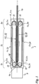
- Fig.1 shows a device for producing plastic pipes 10, with an extruder 9 with an injection head 9s and a corrugator 1.
- a plastic melt hose is introduced into the corrugator via the injection head 9s for forming a plastic pipe 10.
- the corrugator 1 has a forming section 1f in which forming jaws 5 are arranged in pairs (see Fig.3 ) in the direction of production.
- the mold jaws 5 are brought together in an inlet module 2e to form pairs of mold jaws at the beginning of the molding section 1f.
- the molding section 1f is designed as a molding section module 2f in an intermediate section 1z of the corrugator 5 arranged between the inlet section 1e and the outlet section 1a. Furthermore, a return 1r is formed in the intermediate section 1z on both sides of the molding section 1f, namely a return 1r for the left mold jaws and a return 1r for the right mold jaws. In the return 1r, the mold jaws 5 are returned from the end of the molding section 1f to the beginning of the molding section 1f.
- the return 1r, 1r are designed as two separate return modules 2r, 2r. They are arranged parallel to one another.
- the molding section module 2f is arranged in between.
- the pairs of mold jaws arranged one behind the other lie face to face in the molding section.
- a pair of mold jaws comprises two mirror-image mold jaws 5, whose mold surfaces 5f (see Fig.3 ) form the negative mold for the plastic pipe 10 formed in the device.
- the molding surfaces 5f are wave-shaped.
- the molding surfaces 5f of the molding jaw pairs arranged abutting in the molding section 1f form a continuous molding channel.
- the extruder 9 which is only shown schematically, has a nozzle-shaped injection head 9s, the outlet opening of which is arranged at the entrance to the molding section.
- the plastic melt tube is injected into the molding section of the corrugator via the injection head 9s.
- the pressures acting on the inside and outside of the plastic melt tube in the molding section 1f are controlled by appropriate pressure control.
- single-walled and multi-walled plastic tubes can be produced.
- the guide device 6 is formed by guide and/or tempering body devices 8, which are supported in a stationary manner on crossbeams 1q.
- tempering medium channels 8k are formed, through which a tempering medium flows.
- the guide and/or tempering body devices 8 are composed of guide and/or tempering bodies 8i.
- the guide and/or tempering bodies 8i are arranged in such a way that they surround the passing mold jaws 5 above, below and to the side.
- the guide and/or tempering bodies 8i have guide and/or tempering surfaces 8f, on which the passing mold jaws 5 are guided in a sliding manner (see Fig.5 ).
- the guide and/or tempering surfaces 8f are designed to complement the outside of the mold jaws.
- Guide grooves 6n, 8nz, 8ne are formed in the guide and/or tempering surfaces 8f, into which guide pins 5s or, in modified versions, other projections of the mold jaws 5 engage.
- the guide and/or tempering bodies 8i thus form tempering bodies for tempering the mold jaws 5 and at the same time they form guide bodies in or on which the mold jaws 5 are guided.
- the mold surfaces 5f of the mold jaws 5 are indirectly tempered, i.e.
- tempering medium that flows through the tempering medium channels 8k of the guide and/or tempering bodies 8i.
- the temperature of the tempering medium is adjusted such that at least in certain sections of the corrugator, the mold jaws are heated by the guide and/or tempering body device 8.
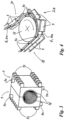
- Figure 5 shows a cross section through the intermediate section 1z.
- the mold section 1f can be seen in the middle and a return line 1r on each of the two sides.
- the guide and/or tempering bodies 8i are formed from elongated base bodies, in each of which two tempering medium channels 8k are arranged.
- the tempering medium channels 8k run along the longitudinal extension direction of the guide and/or tempering bodies 8i.
- a tempering medium flows through the tempering medium channels 8k.
- the mold jaws 5 pass the guide and/or tempering bodies 8i along the longitudinal extension direction of the guide and/or tempering bodies 8i.
- the tempering medium channels 8k extend in the guide direction.
- the guide and/or tempering bodies 8i work together, as already described, with the passing mold jaws 5 for guidance and tempering.
- the guide and/or tempering bodies 8i have the guide and/or tempering surfaces 8f for this purpose, which work together with the guide and/or tempering surfaces of the mold jaws 5.
- the guide and/or tempering surfaces 8f on the guide and tempering body side are formed on the side of the guide and/or tempering bodies 8i facing the associated mold jaws 5.
- the guide and/or tempering surfaces on the mold jaw side are formed on the outside of the mold jaws 5.
- the mold surfaces 5f are formed on the side of the mold jaws 5 facing away from them, and are intended to maintain as uniform a temperature distribution as possible over the entire surface.
- the guide and/or tempering bodies 8i in the mold section module 2f are designed in such a way that the mold jaw pairs are enclosed by the guide and/or tempering bodies 8i.
- the guide and/or tempering bodies 8i enclose the mold jaw pairs on all four long sides, with two lateral guide and/or tempering bodies 8i being in thermal contact with the side surfaces of the mold jaw pairs and two guide and/or tempering bodies 8i being in thermal contact with the top or bottom of the mold jaw pairs.
- the guide and/or tempering bodies 8i arranged in the return modules 2r are designed like the aforementioned guide and/or tempering bodies 8i, but with the difference that the mold jaws 5 in the returns 1r are only surrounded on three long sides by the guide and/or tempering bodies 8i, with the open sides of the mold jaws 5 having the mold surfaces 5f, which are therefore not covered.
- grooves 8nz, 8ne are formed in the upper and lower guide and/or tempering surfaces 8f, in which the upper and lower guide pins 5s of the mold jaws 5 engage.
- the guide pins 5s are formed with a diameter of less than 14 mm.
- the grooves 8nz for guiding the guide pins 5s are formed as in Figure 5 shown, formed by adjacent guide and/or tempering bodies 8i.
- guide grooves 8ne are also formed laterally as one-piece grooves in the guide and/or tempering bodies 8i.
- the toothed strips 5z of the mold jaws 5 engage in these grooves 8ne. This also provides guidance for the mold jaws 5.
- the size of the contact surface between the guide and/or tempering bodies 8i and the mold jaws 5 is influenced and thus at least co-determines the heat transfer.
- FIG.4 Reference should also be made to further guide grooves. These are designed as lower and upper guide grooves 6n in the inlet module 2e and in the outlet module 2a.
- the guide pins 5s of the mold jaws engage in these grooves 6n, forming the guide in the deflection area of the inlet section 1e and the outlet section 1a.
- the guide device for guiding the mold jaws is thus a composite device, composed of the guidance by the guide and/or tempering body devices 8 (see Fig.5 ) and from the guide in the deflection areas in the inlet section 1e and the outlet section 1a.
- the guide grooves 6n, 8nz, 8ne of the guide devices 6, 8, 8i are designed as endless, i.e. continuous guide grooves 6n in which the guide pins 5s arranged on the mold jaws 5 slide in the sense of an endless circulation.
- the mold jaws 5 each have an upper and a lower guide pin 5s, which are arranged on opposite end sections of the mold jaw 5 on the top and bottom of the mold jaw 5. Accordingly, two upper guide grooves 6n, 8nz, 8ne and two lower guide grooves 6n, 8nz, 8ne are formed in the respective guide and/or tempering bodies 8i and in the deflection areas of the inlet and outlet sections 1e, 1a.
- the upper and lower guide grooves have different geometries, whereby the guideways defined by the guide grooves are designed in such a way that the mold jaws 5 perform a pivoting movement in the curved sections of the guideways (see Fig.4 ), as is required in the deflection areas of the inlet and outlet sections.
- the swivel movement minimizes curve wear.
- the guide pins 5s are rigidly connected to the mold jaws 5, for example by means of a press connection.
- the guide pins 5s are rotatably mounted, for example in plain bearings, whereby the aforementioned curve wear is reduced even further.
- the mold jaws 5 each have two toothed strips 5z, which interact with deflection pinions 11 in the inlet module 2e and in the outlet module 2a, as shown in Fig.4 shown. In Fig.4 the gears are not shown.
- the modules arranged in the intermediate section 1z are each made up of two sub-modules.
- Plate-shaped coupling devices 3 are provided to connect adjacent modules.
- the coupling devices 3 are detachably connected to the modules by screw connections.
- the forming section modules 2f are coupled to one another at the end faces by the plate-shaped coupling devices 3.
- the return modules 2r are also coupled to one another at the end faces by coupling devices 3.
- Coupling devices 3 are also arranged in the connection areas to couple the inlet module 2e and the outlet module 2a to the forming section modules 2f and the return modules 2r.
- temperature control channel transfer lines 8u are provided in the coupling modules 3. Reference is made to Figure 6 .
- the temperature control channel diversions 8u have U-shaped diversion channels 8k, the end sections of which correspond to blind holes that penetrate vertically through the side walls of the guide and/or temperature control bodies 8i of the modules and open into the temperature control medium channels 8k.
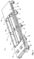
- the guide device 6 in the intermediate section 1z is, as already described, formed by the guide and/or tempering body device 8. This is arranged on a base frame, as the Figures 2 and 5
- the base frame consists of the Figure 2 illustrated case of several spaced-apart base frame parts, in the illustrated case cross beams 1q.
- the inlet module 2e is arranged on its own bearing plate, wherein the bearing plate is supported on two cross beams 1q.
- the outlet module 2a is arranged on two spaced-apart cross beams 1q.
- the inlet module 2e and the outlet module 2a are each coupled by a cross beam 1q to a module of the intermediate section 1z in the connecting areas.
- the modules of the intermediate section 1z are coupled to one another in the connecting areas by a cross beam 1q.
- the cross beams 1q contain channel connections with U-shaped channels for connecting the temperature control channels of the modules.
- the lower temperature control channels 8k of the modules it is also possible for the lower temperature control channels 8k of the modules to be coupled to one another by coupling devices 3 and for the coupling devices 3 to be arranged on the cross beams 1q.
Landscapes
- Engineering & Computer Science (AREA)
- Mechanical Engineering (AREA)
- Manufacturing & Machinery (AREA)
- Extrusion Moulding Of Plastics Or The Like (AREA)
- Moulds For Moulding Plastics Or The Like (AREA)
Description
- Die Erfindung betrifft eine Vorrichtung zum Herstellen von Kunststoffrohren nach dem Oberbegriff des Anspruchs 1.
- Eine derartige Vorrichtung zum Herstellen von Kunststoffrohren ist z.B. in der
WO 2004/052 624 A1 beschrieben. Die Vorrichtung weist einen Extruder mit Spritzkopf und einen Korrugator auf, in den über den Spritzkopf ein Kunststoffschmelzeschlauch zum Ausformen des Kunststoffrohres eingeleitet wird. Der Korrugator weist eine Formstrecke auf, in der Formbacken paarweise in Produktionsrichtung geführt werden. In einem Einlaufabschnitt des Korrugators werden die Formbacken zu Formbackenpaaren zum Anfang der Formstrecke zusammengeführt. In einem Auslaufabschnitt des Korrugators werden die Formbackenpaare vom Ende der Formstrecke auseinander geführt. In einer zwischen dem Einlaufabschnitt und dem Auslaufabschnitt angeordneten Zwischenabschnitt des Korrugators ist die Formstrecke zur Führung der Formbackenpaare ausgebildet und eine Rückführung ausgebildet, in der die Formbacken vom Ende der Formstrecke zum Anfang der Formstrecke rückgeführt werden. - Eine derartige Vorrichtung zur Herstellung von gewellten Kunststoffrohren ist auch aus der
DE 10 2008 021 237 A1 bekannt. - Aus der
US 4 633 699 ist eine Anlage zur Herstellung eines langen Kabels bekannt, wobei gebogene schienenartige Abschnitte der Außen- und Innenwand der Formstrecke in Nuten an der Ober- und Unterseite der Formbacken eingreifen und die Formbacken dadurch geführt werden. - Aus der
US 4 504 206 A ist ein Korrugator mit zweiteiligen Formbacken bekannt. Die Formbacken weisen jeweils vier Führungsrollen auf, welche als unabhängig voneinander drehbare Rollen ausgebildet sind. - Aus der
EP 1 897 671 A1 ist ein Korrugator mit einer Führungs- und/oder Temperierkörpereinrichtung für Formbacken bekannt. Die Umlenkbereiche sind als sogenannte Führungsblöcke ausgebildet. - Bekannt sind bereits Vorrichtungen zum Herstellen von Kunststoffrohren mit Formbacken, die drehbar gelagerte Rollen aufweisen, die zur Führung der Formbacken in eine gemeinsame Nut eingreifen. Durch die Größe der Lager und der Rollen ist eine solche Führung bei Formbacken für Kunststoffrohren mit kleinem Durchmesser bis 75 mm nicht ohne weiteres möglich.
- Aufgabe der vorliegenden Erfindung ist es, eine hinsichtlich der Führung der Formbacken verbesserte Vorrichtung zum Herstellen von Kunststoffrohren anzugeben.
- Erfindungsgemäß wird diese Aufgabe mit dem Gegenstand des Anspruchs 1 gelöst. Bei der Lösung handelt es sich um eine Vorrichtung zum Herstellen von Kunststoffrohren, mit einem Extruder mit Spritzkopf und einem Korrugator, in den über den Spritzkopf ein Kunststoffschmelzeschlauch zum Ausformen des Kunststoffrohres eingeleitet wird. Es ist vorgesehen, dass der Korrugator eine Formstrecke aufweist, in der Formbacken paarweise in Produktionsrichtung geführt werden.
- Ferner ist vorgesehen, dass in einem Einlaufabschnitt des Korrugators die Formbacken zu Formbackenpaaren zum Anfang der Formstrecke zusammengeführt werden.
- Die Vorrichtung sieht vor, dass in einem Auslaufabschnitt des Korrugators die Formbackenpaare vom Ende der Formstrecke auseinander geführt werden. Ferner sieht eine solche Vorrichtung vor, dass in einem zwischen dem Einlaufabschnitt und dem Auslaufabschnitt angeordneten Zwischenabschnitt des Korrugators die Formstrecke zur Führung der Formbackenpaare ausgebildet ist und eine Rückführung ausgebildet ist, in der die Formbacken vom Ende der Formstrecke zum Anfang der Formstrecke rückgeführt werden. Die Lösung sieht eine ortsfeste Führungseinrichtung zur Führung der Formbacken vor.
- Wesentlich ist hierbei, dass jeder Formbacken nur zwei Führungsstifte aufweist, und zwar einen ersten Führungsstift und einen zweiten Führungsstift und die Formbacken in der Führungseinrichtung geführt sind, indem der erste Führungsstift mit seinem freien Ende in eine erste Führungsnut der Führungseinrichtung eingreift und der zweite Führungsstift mit seinem freien Ende in eine zweite Führungsnut der Führungseinrichtung eingreift.
- Die Führungseinrichtung mit den Führungsstiften, die mit ihrem freien Ende vorzugsweise unmittelbar in die Führungsnuten eingreifen, ist konstruktiv besonders einfach und kompakt ausführbar.
- Erfindungsgemäß ist vorgesehen, dass die Führungseinrichtung zur Führung der Formbacken eine zusammengesetzte Einrichtung ist, zusammengesetzt aus einer Führung durch die Führungs- und Temperierkörpereinrichtung in dem Zwischenabschnitt des Korrugators ausgebildet und aus einer Führung in den Umlenkbereichen im Einlaufabschnitt und im Auslaufabschnitt. Wobei zur Ausbildung der Führung im Umlenkbereich des Einlaufabschnitts und des Auslaufabschnitts untere und obere Führungsnuten vorgesehen sind, in die die Führungsstifte der Formbacken eingreifen, wobei die Formbacken als den ersten Führungsstift und den zweiten Führungsstift jeweils einen oberen und einen unteren Führungsstift aufweisen, die an entgegengesetzten Endabschnitten des Formbackens jeweils auf der Oberseite bzw. der Unterseite des Formbackens angeordnet sind, und die oberen und die unteren Führungsnuten unterschiedliche Geometrien aufweisen, wobei die durch die Führungsnuten definierten Führungsbahnen so ausgebildet sind, dass die Formbacken in den Kurvenabschnitten der Führungsbahnen eine Schwenkbewegung ausführen, wie dies in den Umlenkbereichen der Ein- und Auslaufabschnitte erforderlich ist.
- Was die Ausgestaltung des Führungsstifts betrifft, kann vorgesehen sein, dass der erste Führungsstift und/oder der zweite Führungsstift jeweils als einstückiger Führungsstift oder als mehrteiliger, vorzugsweise aus mehreren stiftförmigen Teilen zusammengesetzter Führungsstift ausgebildet ist.
- Eine besonders gute Führung ergibt sich erfindungsgemäß mit der Ausführung, die vorsieht, dass der erste Führungsstift und der zweite Führungsstift jeweils so ausgebildet ist, dass das in die Führungsnut eingreifende freie Ende des Führungsstifts als ein bewegungsfestes Teil des Führungsstiftes ausgebildet ist.
- Konstruktiv besonders einfache Lösungen ergeben sich, wenn vorgesehen ist, dass der erste Führungsstift und/oder der zweite Führungsstift jeweils so ausgebildet ist, dass das in die Führungsnut eingreifende Ende des Führungsstifts als einstückiges Teil des Führungsstiftes ausgebildet ist.
- Besonders vorteilhafte Ausführungen können vorsehen, dass der erste Führungsstift und/oder der zweite Führungsstift jeweils so ausgebildet ist, dass der Führungsstift zumindest im Bereich seines freien Endes gehärtet ausgebildet ist.
- Es kann mit besonderem Vorteil vorgesehen sein, dass der erste Führungsstift und/oder der zweite Führungsstift jeweils so ausgebildet ist, dass der Führungsstift zumindest im Bereich des freien Endes weicher ausgebildet ist als die Führungsbahn der Führungsnut.
- Eine besonders einfache Fertigung und gutes Funktionieren im Betrieb kann mit der erfindungsgemäßen Ausführung erhalten werden, die vorsieht, dass der erste Führungsstift und der zweite Führungsstift jeweils so ausgebildet ist, dass der Führungsstift in den Formbacken eingepresst oder eingeschweißt oder verschraubt ist.
- Eine besonders praktikable Führung wird erfindungsgemäß erhalten, bei der vorgesehen ist, dass die zwei Führungsstifte an jedem Formbacken zueinander mit einem Abstand angeordnet sind, der entlang der Erstreckung des Formbackens in Produktionsrichtung ausgebildet ist. Erfindungsgemäß ist vorgesehen, dass die zwei Führungsstifte an unterschiedlichen Seiten des Formbackens, an gegenüberliegenden Seiten des Formbackens angeordnet sind.
- Bei erfindungsgemäßen Ausführungen ist vorgesehen, dass die Führungseinrichtung eine Führungs- und/oder Temperierkörpereinrichtung aufweist. Erfindungsgemäß ist vorgesehen, dass in der Führungs- und/oder Temperierflächeneinrichtung der Führungs- und/oder Temperierkörpereinrichtung Erhebungen und/oder Vertiefungen aufweisende Führungsausnehmungen und/oder ebene Führungsflächen ausgebildet sind, die mit korrespondierenden Führungsausnehmungen und/oder Führungsflächen der passierenden Formbacken zusammenwirken.
- Es kann auch vorgesehen sein, dass die Erhebungen und/oder Vertiefungen aufweisenden Führungsausformungen der Führungs- und/oder Temperierkörpereinrichtungen vorzugsweise als Führungsstifte und/oder Führungsnasen ausgebildet sind und/oder als Führungsvertiefungen, vorzugsweise Führungsnuten ausgebildet sind; und
dass die Erhebungen und/oder Vertiefungen aufweisenden Führungsausformungen der Formbacken als Führungsausformungen zum Zusammenwirken mit der Führungs- und/oder Temperierkörpereinrichtung ausgebildet sind. - Konstruktiv besonders einfach und besonders kompakt können Ausführungen gestaltet werden, die vorsehen, dass die Führungs- und/oder Temperierkörpereinrichtung aus mehreren in Führungsrichtung axial hintereinander auf Stoß angeordneten Temperierkörpern ausgebildet ist und/oder aus mehreren quer zur Führungsrichtung nebeneinander angeordneten Temperierkörpern gebildet ist.
- Besondere Kompaktheit und gute Führungseigenschaften werden mit Ausführungen erhalten, die vorsehen, dass mindestens eines der Führungsvertiefungen und/oder der Führungsvorsprünge im Bereich zwischen zwei in Querrichtung benachbarten Führungs- und/oder Temperierkörpern ausgebildet ist, d.h. zusammengesetzt durch Abschnitte von zwei benachbarten Führungs- und/oder Temperierkörpern ausgebildet.
- Alternativ können die Führungsvertiefungen und/oder Führungsvorsprünge auch einstückig jeweils mit nur einem der Führungs- und/oder Temperierkörper ausgebildet sein.
- Die Erfindung wird nun anhand von Ausführungsbeispielen näher erläutert. Es zeigen
- Fig. 1
- ein Ausführungsbeispiel einer erfindungsgemäßen Vorrichtung zum Herstellen von Kunststoffrohren in einer schematischen Draufsicht;
- Fig. 2
- einen Korrugator der Vorrichtung in
Fig. 1 in einer perspektivischen Darstellung; - Fig. 3
- ein Formbackenpaar der Vorrichtung in
Fig. 1 in perspektivischer Darstellung; - Fig. 4
- einen Ausschnitt eines Einlaufabschnitts der Vorrichtung in
Fig. 1 in perspektivischer Darstellung; - Fig. 5
- den Zwischenabschnitt der Vorrichtung in
Fig. 1 mit den Formstrecken und den Rückführungen in einer Schnittdarstellung; - Fig. 6
- ein Kupplungsmodul mit Temperiermittelkanal-Umleitung in einer perspektivischen Schnittdarstellung.
-
Fig. 1 zeigt eine Vorrichtung zum Herstellen von Kunststoffrohren 10, mit einem Extruder 9 mit Spritzkopf 9s und einem Korrugator 1. In den Korrugator wird über den Spritzkopf 9s ein Kunststoffschmelzeschlauch zum Ausformen eines Kunststoffrohres 10 eingeleitet. - Der Korrugator 1 weist eine Formstrecke 1f auf, in der Formbacken 5 paarweise (siehe
Fig. 3 ) in Produktionsrichtung geführt werden. - In einem Einlaufabschnitt 1e des Korrugators 1 werden die Formbacken 5 in einem Einlaufmodul 2e zu Formbackenpaaren zum Anfang der Formstrecke 1f zusammengeführt.
- In einem Auslaufabschnitt 1a des Korrugators 1 werden die Formbackenpaare in einem Auslaufmodul 2a vom Ende der Formstrecke 1f auseinander geführt.
- Die Formstrecke 1f ist in einem zwischen dem Einlaufabschnitt 1e und dem Auslaufabschnitt 1a angeordneten Zwischenabschnitt 1z des Korrugators 5 als Formstreckenmodul 2f ausgebildet. Ferner ist in dem Zwischenabschnitt 1z beidseitig der Formstrecke 1f jeweils eine Rückführung 1r ausgebildet, nämlich eine Rückführung 1r für die linken Formbacken und eine Rückführung 1r für die rechten Formbacken. In den Rückführungen 1r werden die Formbacken 5 vom Ende der Formstrecke 1f zum Anfang der Formstrecke 1f rückgeführt. Die Rückführungen 1r, 1r sind als zwei separate Rückführungsmodule 2r, 2r ausgebildet. Sie sind parallel zueinander angeordnet. Das Formstreckenmodul 2f ist dazwischen angeordnet.
- Die hintereinander angeordneten Formbackenpaare liegen in der Formstrecke stirnseitig aufeinander auf Stoß. Ein Formbackenpaar umfasst zwei spiegelbildlich ausgebildete Formbacken 5, deren Formflächen 5f (siehe
Fig. 3 ) die Negativform für das in der Vorrichtung ausgebildete Kunststoffrohr 10 bilden. Zur Herstellung von Kunststoffwellrohren sind die Formflächen 5f wellenförmig. Die Formflächen 5f der in der Formstrecke 1f auf Stoß angeordneten Formbackenpaare bilden einen durchgehenden Formkanal. - Der in
Fig. 1 nur schematisch dargestellte Extruder 9 weist einen düsenförmigen Spritzkopf 9s auf, dessen Austrittsöffnung am Eingang der Formstrecke angeordnet ist. Über den Spritzkopf 9s wird der Kunststoffschmelzeschlauch in die Formstrecke des Korrugators eingespritzt. Über entsprechende Drucksteuerung werden die an der Innenseite und der an der Außenseite des Kunststoffschmelzeschlauchs in der Formstrecke 1f einwirkenden Drücke gesteuert. Abhängig von der Ausbildung der Düseneinrichtung des Spritzkopfs 9s können ein- und mehrwandige Kunststoffrohre hergestellt werden. - Die Formbacken 5 sind in einer ortsfesten Führungseinrichtung 6 geführt. Wie in den
Figuren 5 und 6 in Verbindung mitFig. 2 erkennbar, wird in dem dargestellten Ausführungsbeispiel die Führungseinrichtung 6 von Führungs- und/oder Temperierkörpereinrichtungen 8 gebildet, die stationär auf Querträgern 1q abgestützt sind. In den Führungs- und/oder Temperierkörpereinrichtungen 8 sind Temperiermittelkanäle 8k ausgebildet, die von einem Temperiermittel durchströmt sind. Die Führungs- und/oder Temperierkörpereinrichtungen 8 sind aus Führungs- und/oder Temperierkörpern 8i zusammengesetzt. Die Führungs- und/oder Temperierkörper 8i sind so angeordnet, dass sie die passierenden Formbacken 5 oberhalb, unterhalb und seitlich umgeben. Die Führungs- und/oder Temperierkörper 8i weisen Führungs- und/oder Temperierflächen 8f auf, an denen die passierenden Formbacken 5 gleitend geführt sind (sieheFig. 5 ). Die Führungs- und/oder Temperierflächen 8f sind komplementär zur Außenseite der Formbacken ausgebildet. In den Führungs- und/oder Temperierflächen 8f sind Führungsnuten 6n, 8nz, 8ne ausgebildet, in die Führungsstifte 5s oder bei abgewandelten Ausführungen andere Vorsprünge der Formbacken 5 eingreifen. Die Führungs- und/oder Temperierkörper 8i bilden somit Temperierungskörper zur Temperierung der Formbacken 5 und gleichzeitig bilden sie Führungskörper, in oder an denen die Formbacken 5 geführt werden. Die Formflächen 5f der Formbacken 5 werden durch das Temperiermedium, das durch die Temperiermittelkanäle 8k der Führungs- und/oder Temperierkörper 8i strömt, indirekt temperiert, d.h. in der Regel gekühlt. Es sind jedoch auch Anwendungen möglich, bei denen die Temperatur des Temperiermittels so eingestellt wird, dass zumindest in bestimmten Abschnitten des Korrugators eine Erwärmung der Formbacken durch die Führungs- und/oder Temperierkörpereinrichtung 8 erfolgt. -
Figur 5 zeigt einen Querschnitt durch den Zwischenabschnitt 1z. Erkennbar ist in der Mitte die Formstrecke 1f und an den beiden Seiten je eine Rückführung 1r. Die Führungs- und/oder Temperierkörper 8i sind aus länglichen Grundkörpern gebildet, in denen jeweils zwei Temperiermittelkanäle 8k angeordnet sind. Die Temperiermittelkanäle 8k verlaufen entlang der Längserstreckungsrichtung der Führungs- und/oder Temperierkörper 8i. Die Temperiermittelkanäle 8k werden von einem Temperiermittel durchströmt. Die Formbacken 5 passieren die Führungs- und/oder Temperierkörper 8i entlang der Längserstreckungsrichtung der Führungs- und/oder Temperierkörper 8i. Die Temperiermittelkanäle 8k erstrecken sich in die Führungsrichtung. - Die Führungs- und/oder Temperierkörper 8i wirken, wie bereits beschrieben, mit den passierenden Formbacken 5 zur Führung und Temperierung zusammen. Die Führungs- und/oder Temperierkörper 8i weisen hierfür die Führungs- und/oder Temperierflächen 8f auf, die mit Führungs- und/oder Temperierflächen der Formbacken 5 zusammenwirken. In dem dargestellten Ausführungsbeispiel sind die führungs- und temperierkörperseitigen Führungs- und/oder Temperierflächen 8f an der den zugeordneten Formbacken 5 zugewandten Seite der Führungs- und/oder Temperierkörper 8i ausgebildet. Die formbackenseitigen Führungs- und/oder Temperierflächen sind an der Außenseite der Formbacken 5 ausgebildet. An der davon abgewandten Seite der Formbacken 5 sind die Formflächen 5f ausgebildet, die über die gesamte Fläche eine möglichst gleichmäßige Temperaturverteilung erhalten sollen.
- Wie
Fig. 5 zeigt, sind die Führungs- und/oder Temperierkörper 8i im Formstreckenmodul 2f so ausgebildet, dass die Formbackenpaare von den Führungs- und/oder Temperierkörpern 8i umschlossen werden. WieFig. 5 entnehmbar, umschließen in der Formstrecke vier Führungs- und/oder Temperierkörper 8i die Formbackenpaare an allen vier Längsseiten, indem zwei seitliche Führungs- und/oder Temperierkörper 8i mit den Seitenflächen der Formbackenpaare in thermischem Kontakt sind und zwei Führungs- und/oder Temperierkörper 8i mit der Oberseite bzw. mit der Unterseite der Formbackenpaare in thermischem Kontakt sind. Die in den Rückführungsmodulen 2r angeordneten Führungs- und/oder Temperierkörper 8i sind wie die vorgenannten Führungs- und/oder Temperierkörper 8i ausgebildet, jedoch mit dem Unterschied, dass die Formbacken 5 in den Rückführungen 1r nur an drei Längsseiten durch die Führungs- und/oder Temperierkörper 8i umgeben sind, wobei die offenen Seiten der Formbacken 5 die Formflächen 5f aufweisen, die also nicht abgedeckt sind. - Zur primären Führung der Formbacken 5 sind, wie bereits beschrieben, Nuten 8nz, 8ne in den oberen und unteren Führungs- und/oder Temperierflächen 8f ausgebildet, in denen die oberen und unteren Führungsstifte 5s der Formbacken 5 eingreifen. In bevorzugten Ausführungen sind die Führungsstifte 5s mit einem Durchmesser kleiner als 14 mm ausgebildet. Die Nuten 8nz zur Führung der Führungsstifte 5s werden, wie in
Figur 5 dargestellt, durch aneinander angrenzende Führungs- und/oder Temperierkörper 8i gebildet. Ferner sind auch seitlich Führungsnuten 8ne als einstückige Nuten in den Führungs- und/oder Temperierkörpern 8i ausgebildet. In diesen Nuten 8ne greifen bei dem dargestellten Ausführungsbeispiel die Zahnleisten 5z der Formbacken 5 ein. Auch dadurch wird eine Führung der Formbacken 5 erhalten. - Durch diese ineinandergreifenden Führungsstrukturen, d.h. die Zahnleisten 5z, die Führungsstifte 6n und/oder ähnliche weiter ineinandergreifende Vertiefungen und Erhöhungen, wird die Größe der Kontaktfläche zwischen den Führungs- und/oder Temperierkörpern 8i und den Formbacken 5 beeinflusst und damit die Wärmeübertragung zumindest mitbestimmt.
- Bezug nehmend auf
Fig. 4 sei noch auf weitere Führungsnuten verwiesen. Diese sind als untere und obere Führungsnuten 6n in dem Einlaufmodul 2e und in dem Auslaufmodul 2a ausgebildet. In diese Nuten 6n greifen die Führungsstifte 5s der Formbacken unter Ausbildung der Führung im Umlenkbereich des Einlaufabschnitts 1e und des Auslaufabschnitts 1a - Die Führungseinrichtung zur Führung der Formbacken ist somit eine zusammengesetzte Einrichtung, zusammengesetzt aus der Führung durch die Führungs- und/oder Temperierkörpereinrichtungen 8 (siehe
Fig. 5 ) und aus der Führung in den Umlenkbereichen im Einlaufabschnitt 1e und im Auslaufabschnitt 1a. - Die Führungsnuten 6n, 8nz, 8ne der Führungseinrichtungen 6, 8, 8i sind als endlose, d.h. jeweils durchgehende Führungsnuten 6n ausgebildet, in denen die an den Formbacken 5 angeordneten Führungsstifte 5s im Sinne eines Endlos-Umlaufs gleiten. Die Formbacken 5 weisen im dargestellten Fall jeweils einen oberen und einen unteren Führungsstift 5s auf, die an entgegengesetzten Endabschnitten des Formbackens 5 jeweils auf der Oberseite bzw. der Unterseite des Formbackens 5 angeordnet sind. Dementsprechend sind zwei obere Führungsnuten 6n, 8nz, 8ne und zwei untere Führungsnuten 6n, 8nz, 8ne in den jeweiligen Führungs- und/oder Temperierkörpern 8i und in den Umlenkbereichen der Ein- und Auslaufabschnitte 1e, 1a ausgebildet. Die oberen und die unteren Führungsnuten weisen unterschiedliche Geometrien auf, wobei die durch die Führungsnuten definierten Führungsbahnen so ausgebildet sind, dass die Formbacken 5 in den Kurvenabschnitten der Führungsbahnen eine Schwenkbewegung ausführen (siehe
Fig. 4 ), wie dies in den Umlenkbereichen der Ein- und Auslaufabschnitte erforderlich ist. Durch die Schwenkbewegung ist der Kurvenverschleiß minimiert. In dem inFig. 3 dargestellten Ausführungsbeispiel sind die Führungsstifte 5s starr mit den Formbacken 5 verbunden, beispielsweise mittels einer Pressverbindung. Es kann aber auch vorgesehen sein, die Führungsstifte 5s drehbar zu lagern, beispielsweise in Gleitlagern, wodurch der besagte Kurvenverschleiß noch weiter reduziert ist. - Die Formbacken 5 weisen im dargestellten Fall jeweils zwei Zahnleisten 5z auf, die im Einlaufmodul 2e und im Auslaufmodul 2a mit Umlenkritzeln 11 zusammenwirken, wie in
Fig. 4 gezeigt. InFig. 4 sind die Verzahnungen nicht dargestellt. - Wie
Fig. 2 sind in dem dargestellten Ausführungsbeispiel die im Zwischenabschnitt 1z angeordneten Module, nämlich das Formstreckenmodul 2f und die beiden Rückführungsmodule 2r jeweils aus zwei Teilmodulen ausgebildet. Zur Verbindung benachbarter Module sind plattenförmige Kupplungseinrichtungen 3 vorgesehen. Die Kupplungseinrichtungen 3 sind durch Schraubverbindungen lösbar mit den Modulen verbunden. Die Formstreckenmodule 2f sind an den Stirnflächen durch die plattenförmigen Kupplungseinrichtungen 3 miteinander gekuppelt. Ebenso sind die Rückführungsmodule 2r an den Stirnflächen durch Kupplungseinrichtungen 3 miteinander gekuppelt. Zur Kupplung des Einlaufmoduls 2e und des Auslaufmoduls 2a mit den Formstreckenmodulen 2f und den Rückführungsmodulen 2r sind ebenfalls Kupplungseinrichtungen 3 in den Verbindungsbereichen angeordnet. - Zur Verbindung der Temperierkanäle 8k benachbarter Module sind Temperierkanalüberleitungen 8u in den Kupplungsmodulen 3 vorgesehen. Es sei verwiesen auf
Figur 6 . Die Temperierkanalumleitungen 8u weisen U-förmige Umleitungskanäle 8k auf, deren Endabschnitte mit Sacklöchern korrespondieren, die die Seitenwandung der Führungs- und/oder Temperierkörper 8i der Module senkrecht durchgreifen und in die Temperiermittelkanäle 8k münden. - Die Führungseinrichtung 6 im Zwischenabschnitt 1z wird, wie bereits beschrieben, durch die Führungs- und/oder Temperierkörpereinrichtung 8 gebildet. Dies ist auf einem Grundgestell angeordnet, wie die
Figuren 2 und5 zeigen. Das Grundgestell besteht in dem inFigur 2 dargestellten Fall aus mehreren zueinander beabstandeten Grundgestellteilen, im dargestellten Fall Querträgern 1q. Das Einlaufmodul 2e ist auf einer eigenen Lagerplatte angeordnet, wobei die Lagerplatte auf zwei Querträgern 1q abgestützt ist. Das Auslaufmodul 2a ist auf zwei zueinander beabstandeten Querträgern 1q angeordnet. Das Einlaufmodul 2e und das Auslaufmodul 2a werden durch jeweils einen Querträger 1q mit einem Modul des Zwischenabschnittes 1z in den Verbindungsbereichen gekuppelt. Die Module des Zwischenabschnittes 1z werden untereinander in den Verbindungsbereichen durch einen Querträger 1q miteinander gekuppelt. Die Querträger 1q enthalten Kanalverbindungen mit U-förmigen Kanälen zur Verbindung der Temperierkanäle der Module. In einem abgewandelten Ausführungsbeispiel ist es auch möglich, dass die unteren Temperierkanäle 8k der Module durch Kupplungseinrichtungen 3 miteinander gekuppelt sind und die Kupplungseinrichtungen 3 auf den Querträgern 1q angeordnet sind. -
- 1
- Korrugator
- 1a
- Auslaufabschnitt
- 1e
- Einlaufabschnitt
- 1f
- Formstrecke
- 1r
- Rückführung
- 1q
- Querträger
- 1z
- Zwischenabschnitt
- 2a
- Auslaufmodul
- 2e
- Einlaufmodul
- 2f
- Formstreckenmodul
- 2r
- Rückführungsmodul
- 3
- Kupplungseinrichtung
- 5
- Formbacken
- 5f
- Formfläche
- 5s
- Führungsstifte
- 5z
- Zahnleisten
- 6
- ortsfeste Führungseinrichtung
- 6n, 8nz, 8ne
- Führungsnut;
- 8
- Führungs- und/oder Temperierkörpereinrichtung
- 8i
- Führungs- und/oder Temperierkörper
- 8k
- Temperierkanal
- 8u
- Temperierkanalumleitung
- 8f
- Temperierfläche
- 9
- Extruder
- 9f
- Formluftzuführung
- 10
- Kunststoffrohr
- 9s
- Spritzkopf
- 11
- Umlenkritzel
Claims (9)
- Vorrichtung (10) zum Herstellen von Kunststoffrohren (10),mit einem Extruder (9) mit Spritzkopf (9s) und einem Korrugator (1), in den über den Spritzkopf (9s) ein Kunststoffschmelzeschlauch zum Ausformen des Kunststoffrohres (10) eingeleitet wird, wobei vorgesehen ist,dass der Korrugator (1) eine Formstrecke (1f) aufweist, in der Formbacken (5) paarweise in Produktionsrichtung geführt werden,dass in einem Einlaufabschnitt (1e) des Korrugators (1) die Formbacken (5) zu Formbackenpaaren zum Anfang der Formstrecke (1f) zusammengeführt werden, unddass in einem Auslaufabschnitt (1a) des Korrugators (1) die Formbackenpaare vom Ende der Formstrecke (1f) auseinander geführt werden, unddass in einem zwischen dem Einlaufabschnitt (1e) und dem Auslaufabschnitt (1a) angeordneten Zwischenabschnitt (1z) des Korrugators (1) die Formstrecke (1f) zur Führung der Formbackenpaare ausgebildet ist und mindestens eine Rückführung (1r) ausgebildet ist, in der die Formbacken (5) vom Ende der Formstrecke (1f) zum Anfang der Formstrecke (1f) rückgeführt werden,mit einer ortsfesten Führungseinrichtung (6, 8, 8i) zur Führung der Formbacken (5),dadurch gekennzeichnet,a) dass jeder Formbacken (5) nur zwei Führungsstifte (5s,5s) aufweist, und zwar einen ersten Führungsstift (5s) und einen zweiten Führungsstift (5s), und die Formbacken (5) in der Führungseinrichtung (6, 8, 8i) geführt sind, indem der erste Führungsstift (5s) mit seinem freien Ende in einer ersten Führungsnut (6n, 8nz) der Führungseinrichtung (6, 8, 8i) eingreift und der zweite Führungsstift (5s) mit seinem freien Ende in eine zweite Führungsnut (6n, 8nz) der Führungseinrichtung (6, 8, 8i) eingreift,- wobei der erste Führungsstift (5s) und der zweite Führungsstift (5s) jeweils so ausgebildet sind,dass das in die Führungsnut (6n, 8nz, 8ne) eingreifende freie Ende des Führungsstifts (5s) als ein bewegungsfestes Teil des Führungsstiftes (5s) ausgebildet ist undder Führungsstift (5s) in den Formbacken (5) eingepresst oder eingeschweißt oder verschraubt ist,- wobei die zwei Führungsstifte (5s) an jedem Formbacken (5) zueinander mit einem Abstand angeordnet sind, der entlang der Erstreckung des Formbackens (5) in Produktionsrichtung ausgebildet ist,- wobei die zwei Führungsstifte (5s) an unterschiedlichen Seiten des Formbackens (5) an gegenüberliegenden Seiten des Formbackens (5) angeordnet sind,b) dass die Führungseinrichtung (6, 8, 8i) eine Führungs- und Temperierkörpereinrichtung (8, 8i) aufweist,- wobei in einer Führungs- und Temperierflächeneinrichtung (8, 8i) der Führungs- und Temperierkörpereinrichtung (8, 8i) Erhebungen und/oder Vertiefungen (8nz, 8ne) aufweisende Führungsausnehmungen und/oder ebene Führungsflächen ausgebildet sind, die mit korrespondierenden Führungsausnehmungen (8nz, 8ne) und/oder Führungsflächen der passierenden Formbacken (5) zusammenwirken,c) dass die Führungseinrichtung zur Führung der Formbacken eine zusammengesetzte Einrichtung ist, zusammengesetzt- aus einer Führung durch die Führungs- und Temperierkörpereinrichtung in dem Zwischenabschnitt des Korrugators ausgebildet und- aus einer Führung in den Umlenkbereichen im Einlaufabschnitt (1e) und im Auslaufabschnitt (1a),- wobei zur Ausbildung der Führung im Umlenkbereich des Einlaufabschnitts (1e) und des Auslaufabschnitts (1a) untere und obere Führungsnuten (6e) vorgesehen sind, in die die Führungsstifte (5s) der Formbacken eingreifen,- wobei die Formbacken (5) als den ersten Führungsstift (5s) und den zweiten Führungsstift (5s) jeweils einen oberen und einen unteren Führungsstift (5s) aufweisen, die an entgegengesetzten Endabschnitten des Formbackens (5) jeweils auf der Oberseite bzw. der Unterseite des Formbackens (5) angeordnet sind, und die oberen und die unteren Führungssnuten unterschiedliche Geometrien aufweisen, wobei die durch die Führungsnuten definierten Führungsbahnen so ausgebildet sind, dass die Formbacken in den Kurvenabschnitten der Führungsbahnen eine Schwenkbewegung ausführen, wie dies in den Umlenkbereichen der Ein- und Auslaufabschnitte erforderlich ist.
- Vorrichtung nach Anspruch 1,
dadurch gekennzeichnet,
dass der erste Führungsstift (5s) und/oder der zweite Führungsstift (5s) jeweils als einstückiger Führungsstift oder als mehrteiliger, vorzugsweise aus mehreren stiftförmigen Teilen zusammengesetzter Führungsstift ausgebildet ist. - Vorrichtung nach einem der vorangehenden Ansprüche,
dadurch gekennzeichnet,
dass der erste Führungsstift (5s) und/oder der zweite Führungsstift (5s) jeweils so ausgebildet ist, dass das in die Führungsnut (6n, 8nz, 8ne) eingreifende Ende des Führungsstifts (5s) als einstückiges Teil des Führungsstiftes (5s) ausgebildet ist. - Vorrichtung nach einem der vorangehenden Ansprüche,
dadurch gekennzeichnet,
dass der erste Führungsstift (5s) und/oder der zweite Führungsstift (5s) jeweils so ausgebildet ist, dass der Führungsstift (5s) zumindest im Bereich seines freien Endes gehärtet ausgebildet ist. - Vorrichtung nach einem der vorangehenden Ansprüche,
dadurch gekennzeichnet,
dass der erste Führungsstift (5s) und/oder der zweite Führungsstift (5s) jeweils so ausgebildet ist, dass der Führungsstift zumindest im Bereich des freien Endes weicher ausgebildet ist als die Führungsbahn der Führungsnut (6n, 8nz, 8ne). - Vorrichtung nach einem der vorangehenden Ansprüche,
dadurch gekennzeichnet,
dass der erste Führungsstift (5s) und/oder der zweite Führungsstift (5s) jeweils so ausgebildet ist, dass der Führungsstift (5s) in dem Formbacken (5) über ein Drehlager drehbar gelagert ist. - Vorrichtung nach einem der vorangehenden Ansprüche,
dadurch gekennzeichnet,dass die Erhebungen und/oder Vertiefungen aufweisenden Führungsausformungen (8nz, 8ne) der Führungs- und/oder Temperierkörpereinrichtungen (8) vorzugsweise als Führungsstifte und/oder Führungsnasen ausgebildet sind und/oder als Führungsvertiefungen (8nz, 8ne), vorzugsweise Führungsnuten ausgebildet sind; unddass die Erhebungen (5s) und/oder Vertiefungen aufweisenden Führungsausformungen der Formbacken (5) als Führungsausformungen (8nz, 8ne) zum Zusammenwirken mit der Führungs- und/oder Temperierkörpereinrichtung (8, 8i) ausgebildet sind. - Vorrichtung nach einem der vorangehenden Ansprüche,
dadurch gekennzeichnet,
dass die Führungs- und/oder Temperierkörpereinrichtung (8) aus mehreren in Führungsrichtung axial hintereinander auf Stoß angeordneten Temperierkörpern (8i) ausgebildet ist und/oder aus mehreren quer zur Führungsrichtung nebeneinander angeordneten Temperierkörpern (8i) gebildet ist. - Vorrichtung nach einem der vorangehenden Ansprüche,
dadurch gekennzeichnet,
dass mindestens eines der Führungsvertiefungen (8nz) und/oder der Führungsvorsprünge im Bereich zwischen zwei in Querrichtung benachbarten Führungs- und/oder Temperierkörpern (8i) ausgebildet ist.
Priority Applications (1)
| Application Number | Priority Date | Filing Date | Title |
|---|---|---|---|
| PL16775107.2T PL3349962T5 (pl) | 2015-09-18 | 2016-09-16 | Urządzenie do wytwarzania rur z tworzyw sztucznych |
Applications Claiming Priority (2)
| Application Number | Priority Date | Filing Date | Title |
|---|---|---|---|
| DE102015115827.2A DE102015115827B3 (de) | 2015-09-18 | 2015-09-18 | Vorrichtung zum Herstellen von Kunststoffrohren |
| PCT/EP2016/072037 WO2017046368A1 (de) | 2015-09-18 | 2016-09-16 | Vorrichtung zum herstellen von kunststoffrohren |
Publications (3)
| Publication Number | Publication Date |
|---|---|
| EP3349962A1 EP3349962A1 (de) | 2018-07-25 |
| EP3349962B1 EP3349962B1 (de) | 2021-10-20 |
| EP3349962B2 true EP3349962B2 (de) | 2024-07-17 |
Family
ID=57047177
Family Applications (1)
| Application Number | Title | Priority Date | Filing Date |
|---|---|---|---|
| EP16775107.2A Active EP3349962B2 (de) | 2015-09-18 | 2016-09-16 | Vorrichtung zum herstellen von kunststoffrohren |
Country Status (7)
| Country | Link |
|---|---|
| US (1) | US10981317B2 (de) |
| EP (1) | EP3349962B2 (de) |
| CA (1) | CA2998791C (de) |
| DE (1) | DE102015115827B3 (de) |
| ES (1) | ES2898914T5 (de) |
| PL (1) | PL3349962T5 (de) |
| WO (1) | WO2017046368A1 (de) |
Families Citing this family (2)
| Publication number | Priority date | Publication date | Assignee | Title |
|---|---|---|---|---|
| CN113172856B (zh) * | 2021-04-13 | 2022-02-18 | 安徽国登新材料科技有限公司 | 一种波纹管生产制造工艺 |
| IT202200001310A1 (it) * | 2022-01-26 | 2023-07-26 | Itib Machinery Int S R L | Semi-stampo per una macchina per la produzione in continuo di tubo corrugato |
Family Cites Families (13)
| Publication number | Priority date | Publication date | Assignee | Title |
|---|---|---|---|---|
| CA87854A (en) * | 1904-04-30 | 1904-06-14 | Howard D. Hazard | Wire grip |
| FR2240094A2 (en) * | 1973-08-08 | 1975-03-07 | Verges Paul | Extrusion blow moulding into mobile flexible moulds - with improved expansion control, wall thickness programming and mould transport |
| US4504206A (en) | 1982-01-21 | 1985-03-12 | Lupke Manfred Arno Alfred | Chainless mold drive for a corrugator or the like |
| DE3364108D1 (en) * | 1982-01-21 | 1986-07-24 | Manfred Arno Alfred Lupke | Chainless mold drive for a corrugator or the like |
| US4633699A (en) * | 1985-03-22 | 1987-01-06 | Fuchs Jr Francis J | Continuous extrusion apparatus |
| US4681526A (en) | 1986-04-09 | 1987-07-21 | Lupke Manfred Arno Alfred | Apparatus for molding thermoplastic pipes |
| WO1991006419A1 (en) | 1989-10-30 | 1991-05-16 | Lupke Manfred Arno Alfred | Apparatus for making plastic tubing including mold blocks hingeably openable and closeable |
| ATE194309T1 (de) | 1994-02-21 | 2000-07-15 | Uponor Innovation Ab | Verfahren und vorrichtung zum herstellen eines kunststoffrohres und kunststoffrohr |
| DE19956880B4 (de) | 1999-11-26 | 2004-07-08 | Henco Industries Nv | Kunststoffrohr mit umgebenden Rippenrohr |
| DE20219027U1 (de) * | 2002-12-09 | 2003-02-27 | Unicor GmbH Rahn Plastmaschinen, 97437 Haßfurt | Vorrichtung zur Herstellung von Querrippenrohren |
| FR2905629B1 (fr) | 2006-09-07 | 2008-11-07 | Corelco Sarl | Bloc de guidage a refroidissement integre pour une installation de fabrication d'un tube moule en matiere plastique |
| DE202008017832U1 (de) * | 2008-04-28 | 2010-09-23 | Maintools Gmbh & Co.Kg | Formvorrichtung, insbesondere Corrugator, zum Herstellen von profilierten Kunststoffrohren |
| DE102008021237A1 (de) * | 2008-04-28 | 2009-10-29 | Maintools Gmbh & Co.Kg | Formvorrichtung, insbesondere Corrugator, zum Herstellen von profilierten Kunststoffrohren |
-
2015
- 2015-09-18 DE DE102015115827.2A patent/DE102015115827B3/de active Active
-
2016
- 2016-09-16 EP EP16775107.2A patent/EP3349962B2/de active Active
- 2016-09-16 WO PCT/EP2016/072037 patent/WO2017046368A1/de not_active Ceased
- 2016-09-16 CA CA2998791A patent/CA2998791C/en active Active
- 2016-09-16 US US15/760,729 patent/US10981317B2/en active Active
- 2016-09-16 ES ES16775107T patent/ES2898914T5/es active Active
- 2016-09-16 PL PL16775107.2T patent/PL3349962T5/pl unknown
Also Published As
| Publication number | Publication date |
|---|---|
| CA2998791C (en) | 2023-09-19 |
| DE102015115827B3 (de) | 2017-02-16 |
| US10981317B2 (en) | 2021-04-20 |
| ES2898914T3 (es) | 2022-03-09 |
| PL3349962T3 (pl) | 2022-02-14 |
| EP3349962A1 (de) | 2018-07-25 |
| EP3349962B1 (de) | 2021-10-20 |
| US20180272591A1 (en) | 2018-09-27 |
| WO2017046368A1 (de) | 2017-03-23 |
| ES2898914T5 (es) | 2024-11-25 |
| CA2998791A1 (en) | 2017-03-23 |
| PL3349962T5 (pl) | 2024-10-14 |
Similar Documents
| Publication | Publication Date | Title |
|---|---|---|
| EP3288741B1 (de) | Reifenstreifen-extrusionsvorrichtung zum herstellen von lauf- und/oder seitenstreifen für reifen und verfahren zum herstellen eines lauf- oder seitenstreifens eines reifens | |
| EP3349961B1 (de) | Vorrichtung zum herstellen von kunststoffrohren | |
| EP0666791B2 (de) | Verfahren zum spritzgiessen von formteilen aus thermoplastischem kunststoffmaterial sowie werkzeug zur durchführung desselben | |
| EP1254014B1 (de) | Vorrichtung zur herstellung von profilierten kunststoff-rohren | |
| CH632429A5 (de) | Kollabierender kern fuer giessformen, insbesondere spritzgiessformen. | |
| EP3349962B2 (de) | Vorrichtung zum herstellen von kunststoffrohren | |
| EP0580984B1 (de) | Vorrichtung zum Herstellen eines Kunststoff-Rohres mit Querprofilierung | |
| EP1360061B1 (de) | Vorrichtung zur herstellung von kunststoffrohren | |
| EP0044389A1 (de) | Verfahren und Vorrichtung zur Herstellung eines Flach-Hohlkörpers | |
| AT413270B (de) | Haltevorrichtung für eine extrusionsdüse | |
| DE10224461A1 (de) | Formgebungseinrichtung für eine Extrusionsanlage | |
| EP2030705A1 (de) | Warmumformwerkzeug | |
| DE19854932C2 (de) | Vakuum-Außenkalibrierung | |
| DE19956554A1 (de) | Heißkanal-Verteiler-System | |
| DE102019127956A1 (de) | Seitenanspritzdüse und spritzgiesswerkzeug | |
| DE2442866C3 (de) | Vorrichtung zur Herstellung eines Profilrohres aus Kunststoff | |
| EP2567763B1 (de) | Formwerkzeug mit innerhalb von Werkzeugteilen verzweigten Kühlkanalbohrungen | |
| DE69706055T2 (de) | Vorrichtung zum Herstellen von rohrähnlichen Gegenständen aus Kunststoff unter Verwendung von Vacuum | |
| DE1596624A1 (de) | Vorrichtung zum Foerdern von Glastafeln laengs eines Gaspolsters | |
| DE1280552B (de) | Vorrichtung zum kontinuierlichen Herstellen von Querrillen, Ausbuchtungen od. dgl. auf einem Rohr aus thermoplastischem Kunststoff | |
| DE69601509T2 (de) | Vakuumzuführkreislauf für eine Anlage zum Herstellen von Wellenrohren | |
| DE19845652C2 (de) | Vorrichtung zum Glätten und Kühlen bzw. Kühlen einer extrudierten Materialbahn | |
| EP4357104A1 (de) | Vorrichtung zum herstellen von kunststoffrohren | |
| EP0024622B1 (de) | Verfahren und Vorrichtung zur Herstellung eines flachen Hohlkörpers | |
| DE102023102683A1 (de) | Vorrichtung zum Herstellen von Kunststoffrohren |
Legal Events
| Date | Code | Title | Description |
|---|---|---|---|
| STAA | Information on the status of an ep patent application or granted ep patent |
Free format text: STATUS: THE INTERNATIONAL PUBLICATION HAS BEEN MADE |
|
| PUAI | Public reference made under article 153(3) epc to a published international application that has entered the european phase |
Free format text: ORIGINAL CODE: 0009012 |
|
| STAA | Information on the status of an ep patent application or granted ep patent |
Free format text: STATUS: REQUEST FOR EXAMINATION WAS MADE |
|
| 17P | Request for examination filed |
Effective date: 20180417 |
|
| AK | Designated contracting states |
Kind code of ref document: A1 Designated state(s): AL AT BE BG CH CY CZ DE DK EE ES FI FR GB GR HR HU IE IS IT LI LT LU LV MC MK MT NL NO PL PT RO RS SE SI SK SM TR |
|
| AX | Request for extension of the european patent |
Extension state: BA ME |
|
| DAV | Request for validation of the european patent (deleted) | ||
| DAX | Request for extension of the european patent (deleted) | ||
| STAA | Information on the status of an ep patent application or granted ep patent |
Free format text: STATUS: EXAMINATION IS IN PROGRESS |
|
| 17Q | First examination report despatched |
Effective date: 20200212 |
|
| REG | Reference to a national code |
Ref country code: DE Ref legal event code: R079 Ref document number: 502016014027 Country of ref document: DE Free format text: PREVIOUS MAIN CLASS: B29C0047120000 Ipc: B29C0048300000 |
|
| GRAP | Despatch of communication of intention to grant a patent |
Free format text: ORIGINAL CODE: EPIDOSNIGR1 |
|
| STAA | Information on the status of an ep patent application or granted ep patent |
Free format text: STATUS: GRANT OF PATENT IS INTENDED |
|
| RIC1 | Information provided on ipc code assigned before grant |
Ipc: B29C 48/25 20190101ALI20210624BHEP Ipc: B29C 48/90 20190101ALI20210624BHEP Ipc: B29C 48/13 20190101ALI20210624BHEP Ipc: B29C 48/09 20190101ALI20210624BHEP Ipc: B29C 48/30 20190101AFI20210624BHEP |
|
| INTG | Intention to grant announced |
Effective date: 20210708 |
|
| GRAS | Grant fee paid |
Free format text: ORIGINAL CODE: EPIDOSNIGR3 |
|
| GRAA | (expected) grant |
Free format text: ORIGINAL CODE: 0009210 |
|
| STAA | Information on the status of an ep patent application or granted ep patent |
Free format text: STATUS: THE PATENT HAS BEEN GRANTED |
|
| AK | Designated contracting states |
Kind code of ref document: B1 Designated state(s): AL AT BE BG CH CY CZ DE DK EE ES FI FR GB GR HR HU IE IS IT LI LT LU LV MC MK MT NL NO PL PT RO RS SE SI SK SM TR |
|
| REG | Reference to a national code |
Ref country code: GB Ref legal event code: FG4D Free format text: NOT ENGLISH |
|
| REG | Reference to a national code |
Ref country code: CH Ref legal event code: EP |
|
| REG | Reference to a national code |
Ref country code: DE Ref legal event code: R096 Ref document number: 502016014027 Country of ref document: DE |
|
| REG | Reference to a national code |
Ref country code: IE Ref legal event code: FG4D Free format text: LANGUAGE OF EP DOCUMENT: GERMAN |
|
| REG | Reference to a national code |
Ref country code: AT Ref legal event code: REF Ref document number: 1439571 Country of ref document: AT Kind code of ref document: T Effective date: 20211115 |
|
| REG | Reference to a national code |
Ref country code: LT Ref legal event code: MG9D |
|
| REG | Reference to a national code |
Ref country code: NL Ref legal event code: MP Effective date: 20211020 |
|
| REG | Reference to a national code |
Ref country code: ES Ref legal event code: FG2A Ref document number: 2898914 Country of ref document: ES Kind code of ref document: T3 Effective date: 20220309 |
|
| REG | Reference to a national code |
Ref country code: DE Ref legal event code: R026 Ref document number: 502016014027 Country of ref document: DE |
|
| PLBI | Opposition filed |
Free format text: ORIGINAL CODE: 0009260 |
|
| PG25 | Lapsed in a contracting state [announced via postgrant information from national office to epo] |
Ref country code: RS Free format text: LAPSE BECAUSE OF FAILURE TO SUBMIT A TRANSLATION OF THE DESCRIPTION OR TO PAY THE FEE WITHIN THE PRESCRIBED TIME-LIMIT Effective date: 20211020 Ref country code: LT Free format text: LAPSE BECAUSE OF FAILURE TO SUBMIT A TRANSLATION OF THE DESCRIPTION OR TO PAY THE FEE WITHIN THE PRESCRIBED TIME-LIMIT Effective date: 20211020 Ref country code: FI Free format text: LAPSE BECAUSE OF FAILURE TO SUBMIT A TRANSLATION OF THE DESCRIPTION OR TO PAY THE FEE WITHIN THE PRESCRIBED TIME-LIMIT Effective date: 20211020 Ref country code: BG Free format text: LAPSE BECAUSE OF FAILURE TO SUBMIT A TRANSLATION OF THE DESCRIPTION OR TO PAY THE FEE WITHIN THE PRESCRIBED TIME-LIMIT Effective date: 20220120 |
|
| 26 | Opposition filed |
Opponent name: WALLINGER RICKER SCHLOTTER TOSTMANN Effective date: 20220329 |
|
| PG25 | Lapsed in a contracting state [announced via postgrant information from national office to epo] |
Ref country code: IS Free format text: LAPSE BECAUSE OF FAILURE TO SUBMIT A TRANSLATION OF THE DESCRIPTION OR TO PAY THE FEE WITHIN THE PRESCRIBED TIME-LIMIT Effective date: 20220220 Ref country code: SE Free format text: LAPSE BECAUSE OF FAILURE TO SUBMIT A TRANSLATION OF THE DESCRIPTION OR TO PAY THE FEE WITHIN THE PRESCRIBED TIME-LIMIT Effective date: 20211020 Ref country code: PT Free format text: LAPSE BECAUSE OF FAILURE TO SUBMIT A TRANSLATION OF THE DESCRIPTION OR TO PAY THE FEE WITHIN THE PRESCRIBED TIME-LIMIT Effective date: 20220221 Ref country code: NO Free format text: LAPSE BECAUSE OF FAILURE TO SUBMIT A TRANSLATION OF THE DESCRIPTION OR TO PAY THE FEE WITHIN THE PRESCRIBED TIME-LIMIT Effective date: 20220120 Ref country code: NL Free format text: LAPSE BECAUSE OF FAILURE TO SUBMIT A TRANSLATION OF THE DESCRIPTION OR TO PAY THE FEE WITHIN THE PRESCRIBED TIME-LIMIT Effective date: 20211020 Ref country code: LV Free format text: LAPSE BECAUSE OF FAILURE TO SUBMIT A TRANSLATION OF THE DESCRIPTION OR TO PAY THE FEE WITHIN THE PRESCRIBED TIME-LIMIT Effective date: 20211020 Ref country code: HR Free format text: LAPSE BECAUSE OF FAILURE TO SUBMIT A TRANSLATION OF THE DESCRIPTION OR TO PAY THE FEE WITHIN THE PRESCRIBED TIME-LIMIT Effective date: 20211020 Ref country code: GR Free format text: LAPSE BECAUSE OF FAILURE TO SUBMIT A TRANSLATION OF THE DESCRIPTION OR TO PAY THE FEE WITHIN THE PRESCRIBED TIME-LIMIT Effective date: 20220121 |
|
| PG25 | Lapsed in a contracting state [announced via postgrant information from national office to epo] |
Ref country code: SM Free format text: LAPSE BECAUSE OF FAILURE TO SUBMIT A TRANSLATION OF THE DESCRIPTION OR TO PAY THE FEE WITHIN THE PRESCRIBED TIME-LIMIT Effective date: 20211020 Ref country code: SK Free format text: LAPSE BECAUSE OF FAILURE TO SUBMIT A TRANSLATION OF THE DESCRIPTION OR TO PAY THE FEE WITHIN THE PRESCRIBED TIME-LIMIT Effective date: 20211020 Ref country code: RO Free format text: LAPSE BECAUSE OF FAILURE TO SUBMIT A TRANSLATION OF THE DESCRIPTION OR TO PAY THE FEE WITHIN THE PRESCRIBED TIME-LIMIT Effective date: 20211020 Ref country code: EE Free format text: LAPSE BECAUSE OF FAILURE TO SUBMIT A TRANSLATION OF THE DESCRIPTION OR TO PAY THE FEE WITHIN THE PRESCRIBED TIME-LIMIT Effective date: 20211020 Ref country code: DK Free format text: LAPSE BECAUSE OF FAILURE TO SUBMIT A TRANSLATION OF THE DESCRIPTION OR TO PAY THE FEE WITHIN THE PRESCRIBED TIME-LIMIT Effective date: 20211020 Ref country code: CZ Free format text: LAPSE BECAUSE OF FAILURE TO SUBMIT A TRANSLATION OF THE DESCRIPTION OR TO PAY THE FEE WITHIN THE PRESCRIBED TIME-LIMIT Effective date: 20211020 |
|
| PLAX | Notice of opposition and request to file observation + time limit sent |
Free format text: ORIGINAL CODE: EPIDOSNOBS2 |
|
| PG25 | Lapsed in a contracting state [announced via postgrant information from national office to epo] |
Ref country code: AL Free format text: LAPSE BECAUSE OF FAILURE TO SUBMIT A TRANSLATION OF THE DESCRIPTION OR TO PAY THE FEE WITHIN THE PRESCRIBED TIME-LIMIT Effective date: 20211020 |
|
| PG25 | Lapsed in a contracting state [announced via postgrant information from national office to epo] |
Ref country code: SI Free format text: LAPSE BECAUSE OF FAILURE TO SUBMIT A TRANSLATION OF THE DESCRIPTION OR TO PAY THE FEE WITHIN THE PRESCRIBED TIME-LIMIT Effective date: 20211020 |
|
| PLAF | Information modified related to communication of a notice of opposition and request to file observations + time limit |
Free format text: ORIGINAL CODE: EPIDOSCOBS2 |
|
| PLBB | Reply of patent proprietor to notice(s) of opposition received |
Free format text: ORIGINAL CODE: EPIDOSNOBS3 |
|
| PG25 | Lapsed in a contracting state [announced via postgrant information from national office to epo] |
Ref country code: MC Free format text: LAPSE BECAUSE OF FAILURE TO SUBMIT A TRANSLATION OF THE DESCRIPTION OR TO PAY THE FEE WITHIN THE PRESCRIBED TIME-LIMIT Effective date: 20211020 |
|
| GBPC | Gb: european patent ceased through non-payment of renewal fee |
Effective date: 20220916 |
|
| REG | Reference to a national code |
Ref country code: BE Ref legal event code: MM Effective date: 20220930 |
|
| PG25 | Lapsed in a contracting state [announced via postgrant information from national office to epo] |
Ref country code: LU Free format text: LAPSE BECAUSE OF NON-PAYMENT OF DUE FEES Effective date: 20220916 |
|
| PG25 | Lapsed in a contracting state [announced via postgrant information from national office to epo] |
Ref country code: IE Free format text: LAPSE BECAUSE OF NON-PAYMENT OF DUE FEES Effective date: 20220916 |
|
| PG25 | Lapsed in a contracting state [announced via postgrant information from national office to epo] |
Ref country code: BE Free format text: LAPSE BECAUSE OF NON-PAYMENT OF DUE FEES Effective date: 20220930 |
|
| PG25 | Lapsed in a contracting state [announced via postgrant information from national office to epo] |
Ref country code: GB Free format text: LAPSE BECAUSE OF NON-PAYMENT OF DUE FEES Effective date: 20220916 |
|
| PG25 | Lapsed in a contracting state [announced via postgrant information from national office to epo] |
Ref country code: HU Free format text: LAPSE BECAUSE OF FAILURE TO SUBMIT A TRANSLATION OF THE DESCRIPTION OR TO PAY THE FEE WITHIN THE PRESCRIBED TIME-LIMIT; INVALID AB INITIO Effective date: 20160916 |
|
| PG25 | Lapsed in a contracting state [announced via postgrant information from national office to epo] |
Ref country code: CY Free format text: LAPSE BECAUSE OF FAILURE TO SUBMIT A TRANSLATION OF THE DESCRIPTION OR TO PAY THE FEE WITHIN THE PRESCRIBED TIME-LIMIT Effective date: 20211020 |
|
| PG25 | Lapsed in a contracting state [announced via postgrant information from national office to epo] |
Ref country code: MK Free format text: LAPSE BECAUSE OF FAILURE TO SUBMIT A TRANSLATION OF THE DESCRIPTION OR TO PAY THE FEE WITHIN THE PRESCRIBED TIME-LIMIT Effective date: 20211020 |
|
| PUAH | Patent maintained in amended form |
Free format text: ORIGINAL CODE: 0009272 |
|
| STAA | Information on the status of an ep patent application or granted ep patent |
Free format text: STATUS: PATENT MAINTAINED AS AMENDED |
|
| 27A | Patent maintained in amended form |
Effective date: 20240717 |
|
| AK | Designated contracting states |
Kind code of ref document: B2 Designated state(s): AL AT BE BG CH CY CZ DE DK EE ES FI FR GB GR HR HU IE IS IT LI LT LU LV MC MK MT NL NO PL PT RO RS SE SI SK SM TR |
|
| REG | Reference to a national code |
Ref country code: DE Ref legal event code: R102 Ref document number: 502016014027 Country of ref document: DE |
|
| PG25 | Lapsed in a contracting state [announced via postgrant information from national office to epo] |
Ref country code: MT Free format text: LAPSE BECAUSE OF FAILURE TO SUBMIT A TRANSLATION OF THE DESCRIPTION OR TO PAY THE FEE WITHIN THE PRESCRIBED TIME-LIMIT Effective date: 20211020 |
|
| REG | Reference to a national code |
Ref country code: ES Ref legal event code: DC2A Ref document number: 2898914 Country of ref document: ES Kind code of ref document: T5 Effective date: 20241125 |
|
| PGFP | Annual fee paid to national office [announced via postgrant information from national office to epo] |
Ref country code: TR Payment date: 20240905 Year of fee payment: 9 |
|
| REG | Reference to a national code |
Ref country code: CH Ref legal event code: U11 Free format text: ST27 STATUS EVENT CODE: U-0-0-U10-U11 (AS PROVIDED BY THE NATIONAL OFFICE) Effective date: 20251001 |
|
| PGFP | Annual fee paid to national office [announced via postgrant information from national office to epo] |
Ref country code: DE Payment date: 20250821 Year of fee payment: 10 |
|
| PGFP | Annual fee paid to national office [announced via postgrant information from national office to epo] |
Ref country code: PL Payment date: 20250730 Year of fee payment: 10 |
|
| PGFP | Annual fee paid to national office [announced via postgrant information from national office to epo] |
Ref country code: FR Payment date: 20250925 Year of fee payment: 10 Ref country code: AT Payment date: 20250918 Year of fee payment: 10 |
|
| PGFP | Annual fee paid to national office [announced via postgrant information from national office to epo] |
Ref country code: IT Payment date: 20250930 Year of fee payment: 10 |
|
| PGFP | Annual fee paid to national office [announced via postgrant information from national office to epo] |
Ref country code: CH Payment date: 20251001 Year of fee payment: 10 |
|
| PGFP | Annual fee paid to national office [announced via postgrant information from national office to epo] |
Ref country code: ES Payment date: 20251020 Year of fee payment: 10 |