EP3349843B1 - Système de gestion de tubulure flexible pour applications pharmaceutiques, liées aux bio-procédés, et applications alimentaires/liées aux produits laitiers - Google Patents
Système de gestion de tubulure flexible pour applications pharmaceutiques, liées aux bio-procédés, et applications alimentaires/liées aux produits laitiers Download PDFInfo
- Publication number
- EP3349843B1 EP3349843B1 EP16847224.9A EP16847224A EP3349843B1 EP 3349843 B1 EP3349843 B1 EP 3349843B1 EP 16847224 A EP16847224 A EP 16847224A EP 3349843 B1 EP3349843 B1 EP 3349843B1
- Authority
- EP
- European Patent Office
- Prior art keywords
- conduit
- tracks
- connector
- channel
- track
- Prior art date
- Legal status (The legal status is an assumption and is not a legal conclusion. Google has not performed a legal analysis and makes no representation as to the accuracy of the status listed.)
- Active
Links
- 235000013305 food Nutrition 0.000 title claims description 7
- 235000013365 dairy product Nutrition 0.000 title claims description 6
- 238000000034 method Methods 0.000 claims description 23
- 238000004587 chromatography analysis Methods 0.000 claims description 3
- 238000010828 elution Methods 0.000 claims description 3
- 230000008569 process Effects 0.000 description 20
- 238000004519 manufacturing process Methods 0.000 description 9
- 239000012530 fluid Substances 0.000 description 7
- 229960000074 biopharmaceutical Drugs 0.000 description 5
- 239000003814 drug Substances 0.000 description 5
- 229940079593 drug Drugs 0.000 description 4
- 239000000047 product Substances 0.000 description 4
- 229920002725 thermoplastic elastomer Polymers 0.000 description 4
- 239000000463 material Substances 0.000 description 3
- 239000004033 plastic Substances 0.000 description 3
- 229920000642 polymer Polymers 0.000 description 3
- 239000000126 substance Substances 0.000 description 3
- 229910000831 Steel Inorganic materials 0.000 description 2
- 238000004140 cleaning Methods 0.000 description 2
- 239000012467 final product Substances 0.000 description 2
- 230000008520 organization Effects 0.000 description 2
- 229920001296 polysiloxane Polymers 0.000 description 2
- 238000011112 process operation Methods 0.000 description 2
- 230000000717 retained effect Effects 0.000 description 2
- 239000010959 steel Substances 0.000 description 2
- 230000001954 sterilising effect Effects 0.000 description 2
- 238000004659 sterilization and disinfection Methods 0.000 description 2
- 230000010757 Reduction Activity Effects 0.000 description 1
- 239000000853 adhesive Substances 0.000 description 1
- 230000001070 adhesive effect Effects 0.000 description 1
- 238000013459 approach Methods 0.000 description 1
- 230000031018 biological processes and functions Effects 0.000 description 1
- 150000001875 compounds Chemical class 0.000 description 1
- 230000006835 compression Effects 0.000 description 1
- 238000007906 compression Methods 0.000 description 1
- 238000010276 construction Methods 0.000 description 1
- 238000012864 cross contamination Methods 0.000 description 1
- 230000001419 dependent effect Effects 0.000 description 1
- 238000011161 development Methods 0.000 description 1
- 230000018109 developmental process Effects 0.000 description 1
- 238000000855 fermentation Methods 0.000 description 1
- 230000004151 fermentation Effects 0.000 description 1
- 238000001914 filtration Methods 0.000 description 1
- 238000003384 imaging method Methods 0.000 description 1
- 238000003780 insertion Methods 0.000 description 1
- 230000037431 insertion Effects 0.000 description 1
- 239000007788 liquid Substances 0.000 description 1
- 238000012423 maintenance Methods 0.000 description 1
- 230000007246 mechanism Effects 0.000 description 1
- 239000002184 metal Substances 0.000 description 1
- 239000007769 metal material Substances 0.000 description 1
- 238000012986 modification Methods 0.000 description 1
- 230000004048 modification Effects 0.000 description 1
- 102000039446 nucleic acids Human genes 0.000 description 1
- 108020004707 nucleic acids Proteins 0.000 description 1
- 150000007523 nucleic acids Chemical class 0.000 description 1
- 235000015097 nutrients Nutrition 0.000 description 1
- 230000037361 pathway Effects 0.000 description 1
- 239000000825 pharmaceutical preparation Substances 0.000 description 1
- 239000002861 polymer material Substances 0.000 description 1
- 238000002360 preparation method Methods 0.000 description 1
- 102000004169 proteins and genes Human genes 0.000 description 1
- 108090000623 proteins and genes Proteins 0.000 description 1
- 239000000376 reactant Substances 0.000 description 1
- 230000009467 reduction Effects 0.000 description 1
- 238000000926 separation method Methods 0.000 description 1
- 239000002699 waste material Substances 0.000 description 1
Images


Classifications
-
- F—MECHANICAL ENGINEERING; LIGHTING; HEATING; WEAPONS; BLASTING
- F16—ENGINEERING ELEMENTS AND UNITS; GENERAL MEASURES FOR PRODUCING AND MAINTAINING EFFECTIVE FUNCTIONING OF MACHINES OR INSTALLATIONS; THERMAL INSULATION IN GENERAL
- F16K—VALVES; TAPS; COCKS; ACTUATING-FLOATS; DEVICES FOR VENTING OR AERATING
- F16K27/00—Construction of housing; Use of materials therefor
-
- A—HUMAN NECESSITIES
- A23—FOODS OR FOODSTUFFS; TREATMENT THEREOF, NOT COVERED BY OTHER CLASSES
- A23C—DAIRY PRODUCTS, e.g. MILK, BUTTER OR CHEESE; MILK OR CHEESE SUBSTITUTES; MAKING THEREOF
- A23C7/00—Other dairy technology
-
- A—HUMAN NECESSITIES
- A61—MEDICAL OR VETERINARY SCIENCE; HYGIENE
- A61J—CONTAINERS SPECIALLY ADAPTED FOR MEDICAL OR PHARMACEUTICAL PURPOSES; DEVICES OR METHODS SPECIALLY ADAPTED FOR BRINGING PHARMACEUTICAL PRODUCTS INTO PARTICULAR PHYSICAL OR ADMINISTERING FORMS; DEVICES FOR ADMINISTERING FOOD OR MEDICINES ORALLY; BABY COMFORTERS; DEVICES FOR RECEIVING SPITTLE
- A61J3/00—Devices or methods specially adapted for bringing pharmaceutical products into particular physical or administering forms
-
- A—HUMAN NECESSITIES
- A61—MEDICAL OR VETERINARY SCIENCE; HYGIENE
- A61M—DEVICES FOR INTRODUCING MEDIA INTO, OR ONTO, THE BODY; DEVICES FOR TRANSDUCING BODY MEDIA OR FOR TAKING MEDIA FROM THE BODY; DEVICES FOR PRODUCING OR ENDING SLEEP OR STUPOR
- A61M25/00—Catheters; Hollow probes
- A61M25/0021—Catheters; Hollow probes characterised by the form of the tubing
- A61M25/0023—Catheters; Hollow probes characterised by the form of the tubing by the form of the lumen, e.g. cross-section, variable diameter
-
- A—HUMAN NECESSITIES
- A61—MEDICAL OR VETERINARY SCIENCE; HYGIENE
- A61M—DEVICES FOR INTRODUCING MEDIA INTO, OR ONTO, THE BODY; DEVICES FOR TRANSDUCING BODY MEDIA OR FOR TAKING MEDIA FROM THE BODY; DEVICES FOR PRODUCING OR ENDING SLEEP OR STUPOR
- A61M39/00—Tubes, tube connectors, tube couplings, valves, access sites or the like, specially adapted for medical use
- A61M39/08—Tubes; Storage means specially adapted therefor
-
- A—HUMAN NECESSITIES
- A61—MEDICAL OR VETERINARY SCIENCE; HYGIENE
- A61M—DEVICES FOR INTRODUCING MEDIA INTO, OR ONTO, THE BODY; DEVICES FOR TRANSDUCING BODY MEDIA OR FOR TAKING MEDIA FROM THE BODY; DEVICES FOR PRODUCING OR ENDING SLEEP OR STUPOR
- A61M39/00—Tubes, tube connectors, tube couplings, valves, access sites or the like, specially adapted for medical use
- A61M39/10—Tube connectors; Tube couplings
-
- A—HUMAN NECESSITIES
- A61—MEDICAL OR VETERINARY SCIENCE; HYGIENE
- A61M—DEVICES FOR INTRODUCING MEDIA INTO, OR ONTO, THE BODY; DEVICES FOR TRANSDUCING BODY MEDIA OR FOR TAKING MEDIA FROM THE BODY; DEVICES FOR PRODUCING OR ENDING SLEEP OR STUPOR
- A61M5/00—Devices for bringing media into the body in a subcutaneous, intra-vascular or intramuscular way; Accessories therefor, e.g. filling or cleaning devices, arm-rests
- A61M5/14—Infusion devices, e.g. infusing by gravity; Blood infusion; Accessories therefor
- A61M5/1414—Hanging-up devices
- A61M5/1418—Clips, separators or the like for supporting tubes or leads
-
- F—MECHANICAL ENGINEERING; LIGHTING; HEATING; WEAPONS; BLASTING
- F16—ENGINEERING ELEMENTS AND UNITS; GENERAL MEASURES FOR PRODUCING AND MAINTAINING EFFECTIVE FUNCTIONING OF MACHINES OR INSTALLATIONS; THERMAL INSULATION IN GENERAL
- F16K—VALVES; TAPS; COCKS; ACTUATING-FLOATS; DEVICES FOR VENTING OR AERATING
- F16K7/00—Diaphragm valves or cut-off apparatus, e.g. with a member deformed, but not moved bodily, to close the passage ; Pinch valves
- F16K7/02—Diaphragm valves or cut-off apparatus, e.g. with a member deformed, but not moved bodily, to close the passage ; Pinch valves with tubular diaphragm
- F16K7/04—Diaphragm valves or cut-off apparatus, e.g. with a member deformed, but not moved bodily, to close the passage ; Pinch valves with tubular diaphragm constrictable by external radial force
- F16K7/07—Diaphragm valves or cut-off apparatus, e.g. with a member deformed, but not moved bodily, to close the passage ; Pinch valves with tubular diaphragm constrictable by external radial force by means of fluid pressure
-
- F—MECHANICAL ENGINEERING; LIGHTING; HEATING; WEAPONS; BLASTING
- F16—ENGINEERING ELEMENTS AND UNITS; GENERAL MEASURES FOR PRODUCING AND MAINTAINING EFFECTIVE FUNCTIONING OF MACHINES OR INSTALLATIONS; THERMAL INSULATION IN GENERAL
- F16L—PIPES; JOINTS OR FITTINGS FOR PIPES; SUPPORTS FOR PIPES, CABLES OR PROTECTIVE TUBING; MEANS FOR THERMAL INSULATION IN GENERAL
- F16L3/00—Supports for pipes, cables or protective tubing, e.g. hangers, holders, clamps, cleats, clips, brackets
- F16L3/08—Supports for pipes, cables or protective tubing, e.g. hangers, holders, clamps, cleats, clips, brackets substantially surrounding the pipe, cable or protective tubing
- F16L3/12—Supports for pipes, cables or protective tubing, e.g. hangers, holders, clamps, cleats, clips, brackets substantially surrounding the pipe, cable or protective tubing comprising a member substantially surrounding the pipe, cable or protective tubing
- F16L3/13—Supports for pipes, cables or protective tubing, e.g. hangers, holders, clamps, cleats, clips, brackets substantially surrounding the pipe, cable or protective tubing comprising a member substantially surrounding the pipe, cable or protective tubing and engaging it by snap action
-
- F—MECHANICAL ENGINEERING; LIGHTING; HEATING; WEAPONS; BLASTING
- F16—ENGINEERING ELEMENTS AND UNITS; GENERAL MEASURES FOR PRODUCING AND MAINTAINING EFFECTIVE FUNCTIONING OF MACHINES OR INSTALLATIONS; THERMAL INSULATION IN GENERAL
- F16L—PIPES; JOINTS OR FITTINGS FOR PIPES; SUPPORTS FOR PIPES, CABLES OR PROTECTIVE TUBING; MEANS FOR THERMAL INSULATION IN GENERAL
- F16L3/00—Supports for pipes, cables or protective tubing, e.g. hangers, holders, clamps, cleats, clips, brackets
- F16L3/24—Supports for pipes, cables or protective tubing, e.g. hangers, holders, clamps, cleats, clips, brackets with a special member for attachment to profiled girders
- F16L3/245—Supports for pipes, cables or protective tubing, e.g. hangers, holders, clamps, cleats, clips, brackets with a special member for attachment to profiled girders the special member embracing the entire profiled girder
-
- A—HUMAN NECESSITIES
- A61—MEDICAL OR VETERINARY SCIENCE; HYGIENE
- A61M—DEVICES FOR INTRODUCING MEDIA INTO, OR ONTO, THE BODY; DEVICES FOR TRANSDUCING BODY MEDIA OR FOR TAKING MEDIA FROM THE BODY; DEVICES FOR PRODUCING OR ENDING SLEEP OR STUPOR
- A61M39/00—Tubes, tube connectors, tube couplings, valves, access sites or the like, specially adapted for medical use
- A61M39/10—Tube connectors; Tube couplings
- A61M2039/1066—Tube connectors; Tube couplings having protection means, e.g. sliding sleeve to protect connector itself, shrouds to protect a needle present in the connector, protective housing, isolating sheath
-
- A—HUMAN NECESSITIES
- A61—MEDICAL OR VETERINARY SCIENCE; HYGIENE
- A61M—DEVICES FOR INTRODUCING MEDIA INTO, OR ONTO, THE BODY; DEVICES FOR TRANSDUCING BODY MEDIA OR FOR TAKING MEDIA FROM THE BODY; DEVICES FOR PRODUCING OR ENDING SLEEP OR STUPOR
- A61M39/00—Tubes, tube connectors, tube couplings, valves, access sites or the like, specially adapted for medical use
- A61M39/22—Valves or arrangement of valves
- A61M2039/229—Stopcocks
-
- A—HUMAN NECESSITIES
- A61—MEDICAL OR VETERINARY SCIENCE; HYGIENE
- A61M—DEVICES FOR INTRODUCING MEDIA INTO, OR ONTO, THE BODY; DEVICES FOR TRANSDUCING BODY MEDIA OR FOR TAKING MEDIA FROM THE BODY; DEVICES FOR PRODUCING OR ENDING SLEEP OR STUPOR
- A61M39/00—Tubes, tube connectors, tube couplings, valves, access sites or the like, specially adapted for medical use
- A61M39/22—Valves or arrangement of valves
- A61M39/28—Clamping means for squeezing flexible tubes, e.g. roller clamps
-
- A—HUMAN NECESSITIES
- A61—MEDICAL OR VETERINARY SCIENCE; HYGIENE
- A61M—DEVICES FOR INTRODUCING MEDIA INTO, OR ONTO, THE BODY; DEVICES FOR TRANSDUCING BODY MEDIA OR FOR TAKING MEDIA FROM THE BODY; DEVICES FOR PRODUCING OR ENDING SLEEP OR STUPOR
- A61M5/00—Devices for bringing media into the body in a subcutaneous, intra-vascular or intramuscular way; Accessories therefor, e.g. filling or cleaning devices, arm-rests
- A61M5/14—Infusion devices, e.g. infusing by gravity; Blood infusion; Accessories therefor
- A61M5/1413—Modular systems comprising interconnecting elements
-
- F—MECHANICAL ENGINEERING; LIGHTING; HEATING; WEAPONS; BLASTING
- F16—ENGINEERING ELEMENTS AND UNITS; GENERAL MEASURES FOR PRODUCING AND MAINTAINING EFFECTIVE FUNCTIONING OF MACHINES OR INSTALLATIONS; THERMAL INSULATION IN GENERAL
- F16L—PIPES; JOINTS OR FITTINGS FOR PIPES; SUPPORTS FOR PIPES, CABLES OR PROTECTIVE TUBING; MEANS FOR THERMAL INSULATION IN GENERAL
- F16L3/00—Supports for pipes, cables or protective tubing, e.g. hangers, holders, clamps, cleats, clips, brackets
- F16L3/26—Supports for pipes, cables or protective tubing, e.g. hangers, holders, clamps, cleats, clips, brackets specially adapted for supporting the pipes all along their length, e.g. pipe channels or ducts
Definitions
- the field of the invention generally relates to conduit or tubing management systems used in connection with pharmaceutical, bioprocess, or food/dairy applications.
- Patent document published US 2,825,524 discloses a valve for a compressible flexible tube.
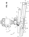
- the actuator 20 may be moved using any number approaches.
- the actuator 20 may be pneumatically actuated valves using air ports 21.
- the actuator 20 may also be manually advanced/retracted using a bonnet or the like that is manually rotated.
- the actuator 20 may also be actuated using a manually-activated toggle-type mechanism that does not require rotation of a bonnet or the like. This enables one to rapidly switch the valve between on/off states.
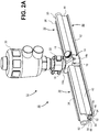
- conduit tracks 30, 32 are illustrated adjacent to the valve 12 with each conduit track 30, 32 being located on opposing sides of the valve 12.
- the conduit tracks 30, 32 are used to hold the flexible conduit 60 in place in the desired spatial configuration (e.g., length, shape, and the like).
- the conduit tracks 30, 32 may be made of any material (e.g., polymer or plastic-based) and are typically rigid or semi-rigid.
- the conduit tracks 30, 32 are straight segments of track although other shapes may be used (e.g., curves, bends and the like may be integrated into the track).
- Each conduit track 30, 32 includes a respective conduit channel 34, 36 that extends along the length of each conduit track 30, 32 and is dimensioned to receive the flexible conduit 60.
- the valve body 14 includes a mounting channel 15 that is located in in the valve body 14 and configured to mate with the retaining members 54 and tab 56 of the connector 50.
- the mounting channel 15 as illustrated in FIGS. 1A and 1B is a notched channel located in one of the two halves 14a, 14b of the valve body 14 that has notched surfaces that engage with the retaining members 54 and tab 56.
- the connector 50 can be inserted laterally into the connector channels 38, 40 and the mounting channel 15.
- the connector 50 may be pressed directly into the connector channels 38, 40 and mounting channel 15 whereby the retaining members 54 flex and then lock into place (e.g., the connector 50 snaps into place after being pressed into the mounting channel 15 and connector channels 38, 40).
- multiple connectors 50 can be used to connect the conduit tracks to the valve body 14.
- a first connector 50 that is secured to the conduit track 30 could partially extend into the mounting channel 15 while a second connector 50 that is secured to the other conduit track 32 could partially extend into the mounting channel 15.
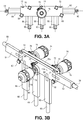
- conduit tracks 84, 86, 88, 90, 92, 93 that are connected to the valve assembly 70 and contain the flexible conduit 60 within respective conduit channels (as described previously, for example, in FIGS. 1A , 1B , 2A , 2B ).
- there are six (6) separate connectors 94 (as described previously, for example, in FIGS. 1A , 1B , 2A , 2B ) that connect the various conduit tracks 84, 86, 88, 90, 92, 93 to the valve assembly 70.
- mounting channels 15 are located in the valve assembly half 70b.
- the connectors 94 could be omitted from the interface between the valve assembly 70 and the conduit tracks 84, 86, 88, 90, 92, 93.
- the valve assembly 70 could have "connectors" integrated in the valve assembly 70. These, for example, could include “male” extensions that are formed integrally into the valve assembly 70 and insert into the connector channels of the conduit tracks 84, 86, 88, 90, 92, 93.
- the conduit tracks 84, 86, 88, 90, 92, 93 that interface with the valve assembly 70 could have "male" ends that integrate with the mounting channels 15.
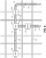
- conduit tracks 106 connects with the curved segment of conduit track 106.
- this example just illustrates a very small portion of the overall hierarchy of the system. Once can imaging that a full manufacturing process will have many different components that are connected together. Thus, many conduit tracks of a variety of different sizes, shapes, and geometries can be employed. Further, while the embodiments described herein have utilized a valve or multiple valves positioned between different conduit tracks there could be other components that are connected to conduit tracks. This includes, for example, pumps, sensors, filters, chromatography columns, reaction volumes (e.g., reactor), reservoirs, manifolds, and the like.
- the various conduit tracks are seen as being located adjacent to the valve body or valve assembly. Note that these adjacent conduit tracks need not necessarily abut with the valve body or valve assembly. There may be a gap between an adjacent conduit track and the valve body/valve assembly. Of course, in other embodiments, the conduit tracks may physically abut with the valve body/valve assembly. Moreover, while the valve body/valve assembly has been described as interfacing with a connector, in some alternative embodiments, the valve body/valve assembly may be secured directly to the conduit track without the need for a separate connector. In addition, in the illustrated embodiments, a clamp 22, 78 is shown connecting the various valves 12, 74 and actuators 20, 76 to the valve body 14 or valve assembly 70. In some alternative embodiments, there are not clamps and the valves 12, 74 with associated actuators 20, 76 are directly secured to the valve body 14 or valve assembly 70.
- the process component may have a mounting channel or other slot that receives the connector so that a conduit channel can be secured relative to the process component.
- the connector acts as a tongue that is inserted into a slot or channel on a conduit track or other process component.
- Various lengths of flexible conduits can be used. For example, multiple segments of flexible conduit may be connected to one another using standard connectors such as clamps can be used. Alternatively, a long length of flexible conduit that traverses many conduit tracks and process components can be used.
Claims (14)
- Système (10) destiné à la gestion d'une tubulure ou d'un conduit flexible (60) que l'on utilise en pharmacologie, dans des processus biologiques ou dans des applications qui concernent des aliments/des produits laitiers, qui comprend :un segment d'une tubulure ou d'un conduit flexible (60) ; etun certain nombre de voies de canalisation (30, 32 ; 84, 86, 88, 90, 92 ; 102, 104, 106), chaque voie de canalisation englobant un canal de canalisation (34, 36) qui est disposé sur un premier côté de la voie en question et qui s'étend sur la longueur de chaque voie de canalisation respective et qui est dimensionné pour recevoir en son sein le segment de tubulure ou de conduit flexible (60), chaque voie de canalisation (30, 32, 102, 104, 106) englobant en outre un canal qui fait office de raccord (38, 40) qui est disposé sur un deuxième côté opposé et qui s'étend sur la longueur de chaque voie de canalisation respective ; dans lequel chaque canal qui fait office de raccord (30, 40) est réalisé par l'intermédiaire d'une paire de parois (42, 44) qui s'étendent à partir des voies de canalisation (34, 36) et qui se terminent à des languettes de retenue respectives (46, 48) ; caractérisé en ce que chaque canal qui fait office de raccord (38, 40) contient un ou plusieurs éléments qui font office de raccords (50 ; 94 ; 108, 110) qui relient des voies de canalisation adjacentes (30, 32 ; 84, 86, 88, 90, 92 ; 102, 104, 106) dans une position bout-à-bout, chacun desdits un ou plusieurs éléments qui font office de raccords (50 ; 94 ; 108, 110) comprenant une base (52) qui comprend une paire d'éléments de retenue (54) qui s'étendent sur une longueur de l'élément qui fait office de raccord (50; 94; 108, 110) ; dans lequel la paire d'éléments de retenue (54) englobe des parois ou des bords angulaires qui possèdent des languettes (56) qui sont formées le long de leur longueur qui entre en contact avec les languettes de retenue correspondantes (46, 48) dans les canaux qui font office de raccords (38, 40).
- Système (10) selon la revendication 1, qui englobe en outre un ou plusieurs éléments qui sont choisis parmi une pompe (122a), une soupape (12, 122b), un capteur (122c), un filtre, une colonne de chromatographie, une colonne dilution, un réacteur, un réservoir et un collecteur, qui est/sont intercalé(s) entre au moins deux voies de canalisation (30, 32 ; 84, 86, 88, 90, 92 ; 102, 104, 106).
- Système (10) selon l'une quelconque des revendications 1 et 2, dans lequel les canaux de canalisation (34, 36) possèdent une configuration en forme de C ou une configuration de forme semi-annulaire.
- Système (10) selon l'une quelconque des revendications 1 à 3, dans lequel lesdites plusieurs voies de canalisation (30, 32 ; 84, 86, 88, 90, 92 ; 102, 104, 106) et le segment de tubulure ou de conduit flexible (60) sont montés sur une structure qui fait office de charpente ou qui fait office de support, en utilisant des éléments de fixation.
- Système (10) selon la revendication 4, dans lequel la structure qui fait office de charpente ou qui fait office de support est située sur un chariot.
- Système (10) selon l'une quelconque des revendications 1 à 5, dans lequel lesdites plusieurs voies de canalisation (30, 32 ; 84, 86, 88, 90, 92 ; 102, 104, 106) comprennent des voies de canalisation qui possèdent des configurations de formes différentes.
- Système (10) selon la revendication 6, dans lequel lesdites plusieurs voies de canalisation (102, 104, 106) comprennent des voies de canalisation de forme rectiligne (102, 104) et des voies de canalisation de forme courbe (106).
- Système (10) selon l'une quelconque des revendications 1 à 7, qui comprend en outre un corps de soupape (14) ou un assemblage de soupape (12 ; 74 ; 100) qui contient la tubulure ou le conduit flexible (60) en son sein et qui fait office d'interface avec une ou plusieurs des voies de localisation (30, 32 ; 84, 86, 88, 90, 92 ; 102, 104, 106).
- Système (10) selon la revendication 8, dans lequel le corps de soupape (14) ou l'assemblage de soupape (12 ; 74 ; 100) comprend un canal de montage (15) ; et dans lequel la paire de parois ou de bords angulaires (54) des éléments de retenue (54) est configurée pour s'accoupler au canal de montage (15).
- Système (10) selon la revendication 9, dans lequel le canal de montage (15) comprend un canal muni d'une encoche et les parois ou les bords angulaires (54) avec les pattes de retenue respectives (56) entrent en contact avec le canal muni d'une encoche dans le but de fixer le corps de soupape (14) ou l'assemblage de soupape (12 ; 74, 100) à l'élément qui fait office de raccord.
- Système (10) selon l'une quelconque des revendications 8 à 10, dans lequel le corps de soupape (14) ou l'assemblage de soupape (12) fait office d'interface avec une première voie de canalisation (30) et avec une deuxième voie de canalisation (32), de même qu'avec un élément unique qui fait office de raccord (50) ; dans lequel la longueur de l'élément qui fait office de raccord (5) est telle que ce dernier traverse le corps de soupape (14), de même que la première et la deuxième voie de canalisation (30, 32).
- Système (10) selon l'une quelconque des revendications 1 à 11, dans lequel chaque voie de canalisation (34, 36) est continue sur la longueur de la voie de canalisation respective.
- Système (10) selon l'une quelconque des revendications 1 à 11, dans lequel chaque voie de canalisation (34, 36) est interrompue sur la longueur de la voie de canalisation respective.
- Procédé destiné à l'utilisation du système selon l'une quelconque des revendications 1 à 13, qui comprend le fait de retirer et le fait d'insérer le segment de tubulure ou de conduit flexible dans les canaux de canalisation desdites plusieurs voie de canalisation.
Priority Applications (1)
| Application Number | Priority Date | Filing Date | Title |
|---|---|---|---|
| EP21174602.9A EP3950042A1 (fr) | 2015-09-15 | 2016-09-14 | Système de gestion de tubulure flexible pour applications pharmaceutiques, liées aux bio-procédés, et applications alimentaires/liées aux produits laitiers |
Applications Claiming Priority (2)
| Application Number | Priority Date | Filing Date | Title |
|---|---|---|---|
| US201562218974P | 2015-09-15 | 2015-09-15 | |
| PCT/US2016/051714 WO2017048831A1 (fr) | 2015-09-15 | 2016-09-14 | Système de gestion de tubulure flexible pour applications pharmaceutiques, liées aux bio-procédés, et applications alimentaires/liées aux produits laitiers |
Related Child Applications (2)
| Application Number | Title | Priority Date | Filing Date |
|---|---|---|---|
| EP21174602.9A Division-Into EP3950042A1 (fr) | 2015-09-15 | 2016-09-14 | Système de gestion de tubulure flexible pour applications pharmaceutiques, liées aux bio-procédés, et applications alimentaires/liées aux produits laitiers |
| EP21174602.9A Division EP3950042A1 (fr) | 2015-09-15 | 2016-09-14 | Système de gestion de tubulure flexible pour applications pharmaceutiques, liées aux bio-procédés, et applications alimentaires/liées aux produits laitiers |
Publications (3)
| Publication Number | Publication Date |
|---|---|
| EP3349843A1 EP3349843A1 (fr) | 2018-07-25 |
| EP3349843A4 EP3349843A4 (fr) | 2019-05-15 |
| EP3349843B1 true EP3349843B1 (fr) | 2021-06-30 |
Family
ID=58289848
Family Applications (2)
| Application Number | Title | Priority Date | Filing Date |
|---|---|---|---|
| EP16847224.9A Active EP3349843B1 (fr) | 2015-09-15 | 2016-09-14 | Système de gestion de tubulure flexible pour applications pharmaceutiques, liées aux bio-procédés, et applications alimentaires/liées aux produits laitiers |
| EP21174602.9A Pending EP3950042A1 (fr) | 2015-09-15 | 2016-09-14 | Système de gestion de tubulure flexible pour applications pharmaceutiques, liées aux bio-procédés, et applications alimentaires/liées aux produits laitiers |
Family Applications After (1)
| Application Number | Title | Priority Date | Filing Date |
|---|---|---|---|
| EP21174602.9A Pending EP3950042A1 (fr) | 2015-09-15 | 2016-09-14 | Système de gestion de tubulure flexible pour applications pharmaceutiques, liées aux bio-procédés, et applications alimentaires/liées aux produits laitiers |
Country Status (6)
| Country | Link |
|---|---|
| US (3) | US10612681B2 (fr) |
| EP (2) | EP3349843B1 (fr) |
| JP (2) | JP6955769B2 (fr) |
| KR (1) | KR102653403B1 (fr) |
| CN (1) | CN108025168B (fr) |
| WO (1) | WO2017048831A1 (fr) |
Families Citing this family (7)
| Publication number | Priority date | Publication date | Assignee | Title |
|---|---|---|---|---|
| JP6955769B2 (ja) * | 2015-09-15 | 2021-10-27 | アルフィニティ, エルエルシーAlphinity, Llc | 医薬品、バイオプロセス、及び食品/乳製品用の可撓性チューブ管理システム |
| WO2018144391A1 (fr) | 2017-01-31 | 2018-08-09 | Alphinity, Llc | Récipients de biotraitement à pompe intégrée |
| EP3381530A1 (fr) | 2017-03-29 | 2018-10-03 | EMD Millipore Corporation | Installation de traitement de liquide biologique |
| EP3381529A1 (fr) | 2017-03-29 | 2018-10-03 | EMD Millipore Corporation | Installation de traitement de liquide biologique |
| CN109578691B (zh) * | 2018-12-25 | 2020-07-24 | 嵊州市越通非开挖建设有限公司 | 一种用于倾斜面管道整体安装装置 |
| EP4216900A4 (fr) * | 2020-09-22 | 2024-03-13 | Alphinity Usa Inc | Systèmes et procédés pour la préparation de liquides destinés à des applications pharmaceutiques et de bioprocédés |
| CN114576387A (zh) * | 2022-02-17 | 2022-06-03 | 马俊 | 一种流体软管夹管阀 |
Family Cites Families (55)
| Publication number | Priority date | Publication date | Assignee | Title |
|---|---|---|---|---|
| US2825524A (en) * | 1956-12-17 | 1958-03-04 | Knox P Fox | Pinch valve |
| US2931387A (en) | 1957-08-22 | 1960-04-05 | Robertson Co H H | Control apparatus for domestic water distribution system |
| GB1055426A (en) | 1963-11-22 | 1967-01-18 | Kelsto Engineering Company Ltd | Improvements in or relating to pinch valves |
| US4254797A (en) | 1979-01-26 | 1981-03-10 | Bi-M Instrument Company | Apparatus for producing calibration gases suitable for analytical instrumentation |
| US4993456A (en) | 1982-03-02 | 1991-02-19 | Akos Sule | Pinch valve assembly |
| US4618114A (en) * | 1982-09-29 | 1986-10-21 | Lof Plastics Inc. | Conduit spacer and support |
| FR2576386B1 (fr) | 1985-01-18 | 1987-03-20 | Lesourd Hugues | Robinet relie a au moins deux canalisations d'alimentation, destine notamment aux installations sanitaires et servant a la fourniture separee ou melangee d'au moins deux liquides differents |
| JPS647979U (fr) | 1987-07-03 | 1989-01-17 | ||
| US4895341A (en) | 1988-09-30 | 1990-01-23 | Whitey Co. | Pinch valve |
| US5165874A (en) * | 1990-05-04 | 1992-11-24 | Block Medical, Inc. | Disposable infusion apparatus and peristaltic pump for use therewith |
| US5078683A (en) * | 1990-05-04 | 1992-01-07 | Block Medical, Inc. | Programmable infusion system |
| DE4224167C2 (de) * | 1992-07-22 | 1994-11-24 | Bundesrep Deutschland | Vorrichtung zur Halterung von Katheteranschlüssen |
| US5197708A (en) | 1992-08-11 | 1993-03-30 | Flow-Rite Controls, Ltd. | Tubing pinch valve device |
| US5402823A (en) * | 1992-12-07 | 1995-04-04 | George S. Cole & Associates, Incorporated | Pinch valve |
| US5350290A (en) | 1993-01-19 | 1994-09-27 | Amf Machinery Systems, Inc. | Manifold and valving arrangement for dough divider |
| US5549134A (en) | 1994-05-27 | 1996-08-27 | Marcvalve Corporation | Diaphragm valve |
| JP3486238B2 (ja) * | 1994-09-21 | 2004-01-13 | Smc株式会社 | 切換弁 |
| BR9610517A (pt) * | 1995-09-21 | 1999-03-30 | Abbott Lab | Válvula de estreitamento que responde à tração |
| US6068751A (en) | 1995-12-18 | 2000-05-30 | Neukermans; Armand P. | Microfluidic valve and integrated microfluidic system |
| US5901745A (en) | 1997-06-19 | 1999-05-11 | The Hoover Company | Multi-solution dispensing valve |
| BR9810024A (pt) | 1997-07-03 | 2000-09-19 | Precision Dispensing Systems L | Mecanismo de compressão adequado para uso como uma válvula ou como parte de uma bomba |
| JP4023638B2 (ja) * | 1997-09-17 | 2007-12-19 | 因幡電機産業株式会社 | 配管カバー |
| US6036166A (en) | 1997-09-25 | 2000-03-14 | Imi Cornelius Inc. | Chamber valve |
| IT1297329B1 (it) | 1997-11-26 | 1999-09-01 | Teseo Srl | Sistema di elementi per la formazione di tubazioni modulari in profilo estruso |
| US7048007B2 (en) * | 1998-03-05 | 2006-05-23 | Swagelok Company | Modular surface mount manifold assemblies |
| CN1289851C (zh) | 1998-03-05 | 2006-12-13 | 斯瓦戈洛克公司 | 歧管系统 |
| US6036107A (en) * | 1998-03-31 | 2000-03-14 | Spraying System Co. | Control valve arrangement for spraying systems |
| JP2003526759A (ja) * | 1998-05-18 | 2003-09-09 | スウエイジロク・カンパニー | モジュール式面取付型マニホルド組立体 |
| AU1320500A (en) | 1998-10-23 | 2000-05-15 | Chemand Corporation | Fluid handling port array |
| DE10035763B4 (de) | 2000-07-22 | 2006-07-27 | Nucellsys Gmbh | Vorrichtung zum Dosieren eines gasförmigen Mediums |
| US7500949B2 (en) * | 2002-03-01 | 2009-03-10 | Medtronic Minimed, Inc. | Multilumen catheter |
| US7104275B2 (en) | 2002-04-01 | 2006-09-12 | Emerson Electric Co. | Pinch valve |
| US20040163711A1 (en) | 2003-02-20 | 2004-08-26 | Graham Packaging Company, L.P. | Fluid regulating pinch valve |
| JP2004293769A (ja) | 2003-03-28 | 2004-10-21 | Japan Aviation Electronics Industry Ltd | 流量コントローラ |
| US6799607B1 (en) | 2003-06-18 | 2004-10-05 | Pbm, Inc. | Sanitary conduit support systems and methods |
| US6976664B2 (en) | 2003-08-11 | 2005-12-20 | Mitos Technologies, Inc. | Free flow valve and element |
| US8038639B2 (en) | 2004-11-04 | 2011-10-18 | Baxter International Inc. | Medical fluid system with flexible sheeting disposable unit |
| US7048008B2 (en) * | 2004-04-13 | 2006-05-23 | Ultra Clean Holdings, Inc. | Gas-panel assembly |
| JP4597564B2 (ja) * | 2004-04-28 | 2010-12-15 | 矢崎総業株式会社 | クリップ構造及び線条体の固定方法 |
| US7383853B2 (en) | 2004-09-07 | 2008-06-10 | Parker-Hannifin Corp. | Multi-port free flow valve and element |
| US7819139B2 (en) | 2005-07-14 | 2010-10-26 | Pdc Facilities, Inc. | Liner for a flow meter |
| US20070295867A1 (en) | 2006-06-21 | 2007-12-27 | Hennon John | Conduit support apparatus |
| EP2049821A4 (fr) | 2006-07-21 | 2013-09-04 | Amgen Inc | Soupape de rupture |
| JP4994082B2 (ja) | 2007-03-30 | 2012-08-08 | 旭有機材工業株式会社 | 配管部材 |
| US8091455B2 (en) * | 2008-01-30 | 2012-01-10 | Cummins Filtration Ip, Inc. | Apparatus, system, and method for cutting tubes |
| FR2939348B1 (fr) | 2008-12-10 | 2014-10-10 | Sartorius Stedim Biotech Sa | Sectionnement d'un tube souple destine a des applications biopharmaceutiques |
| US8282046B2 (en) * | 2009-02-12 | 2012-10-09 | Becton, Dickinson And Company | Systems and methods for organizing and priming an IV administration set |
| US8235067B2 (en) | 2009-05-15 | 2012-08-07 | Alphabio, Inc. | Encapsulated valve system |
| JP5364493B2 (ja) | 2009-07-29 | 2013-12-11 | 株式会社ブリヂストン | ヘッダー固定具、及び、ヘッダー固定構造 |
| DE102010043865A1 (de) * | 2009-11-30 | 2011-07-14 | Horiba Stec Co., Ltd. | Fluid device |
| FR2961711B1 (fr) * | 2010-06-23 | 2012-08-17 | Millipore Corp | Poche pour circuit d'une installation de traitement de liquide biologique |
| US8979070B2 (en) * | 2010-09-10 | 2015-03-17 | William Keizer | Clamshell housing for dispensing tube of metering dispenser |
| FR2970315A1 (fr) | 2011-01-07 | 2012-07-13 | Peugeot Citroen Automobiles Sa | Dispositif de renfort d'un element flexible, de type tuyau ou cable, entre deux points de fixation |
| US20120286110A1 (en) * | 2011-05-10 | 2012-11-15 | Hill Douglas C | Conduit support |
| JP6955769B2 (ja) * | 2015-09-15 | 2021-10-27 | アルフィニティ, エルエルシーAlphinity, Llc | 医薬品、バイオプロセス、及び食品/乳製品用の可撓性チューブ管理システム |
-
2016
- 2016-09-14 JP JP2018513355A patent/JP6955769B2/ja active Active
- 2016-09-14 CN CN201680053229.9A patent/CN108025168B/zh active Active
- 2016-09-14 US US15/759,794 patent/US10612681B2/en active Active
- 2016-09-14 EP EP16847224.9A patent/EP3349843B1/fr active Active
- 2016-09-14 KR KR1020187010190A patent/KR102653403B1/ko active IP Right Grant
- 2016-09-14 WO PCT/US2016/051714 patent/WO2017048831A1/fr active Application Filing
- 2016-09-14 EP EP21174602.9A patent/EP3950042A1/fr active Pending
-
2020
- 2020-02-18 US US16/794,160 patent/US11231120B2/en active Active
-
2021
- 2021-08-17 US US17/404,495 patent/US11578809B2/en active Active
- 2021-09-27 JP JP2021156313A patent/JP7278639B2/ja active Active
Non-Patent Citations (1)
| Title |
|---|
| None * |
Also Published As
| Publication number | Publication date |
|---|---|
| JP2018534491A (ja) | 2018-11-22 |
| US11231120B2 (en) | 2022-01-25 |
| KR102653403B1 (ko) | 2024-04-02 |
| US20210372540A1 (en) | 2021-12-02 |
| EP3349843A4 (fr) | 2019-05-15 |
| EP3349843A1 (fr) | 2018-07-25 |
| US10612681B2 (en) | 2020-04-07 |
| JP6955769B2 (ja) | 2021-10-27 |
| US11578809B2 (en) | 2023-02-14 |
| WO2017048831A1 (fr) | 2017-03-23 |
| JP2022003272A (ja) | 2022-01-11 |
| KR20180052716A (ko) | 2018-05-18 |
| CN108025168B (zh) | 2021-05-04 |
| US20200326004A1 (en) | 2020-10-15 |
| EP3950042A1 (fr) | 2022-02-09 |
| US20180252326A1 (en) | 2018-09-06 |
| CN108025168A (zh) | 2018-05-11 |
| JP7278639B2 (ja) | 2023-05-22 |
Similar Documents
| Publication | Publication Date | Title |
|---|---|---|
| EP3349843B1 (fr) | Système de gestion de tubulure flexible pour applications pharmaceutiques, liées aux bio-procédés, et applications alimentaires/liées aux produits laitiers | |
| US11898645B2 (en) | Valve assembly with directional flow path | |
| US20210254729A1 (en) | Encapsulated valve system and method of use | |
| EP2831474B1 (fr) | Dispositif servant à distribuer un fluide d'essai | |
| EP3234424B1 (fr) | Système encapsulé pour traitements de fluide sous pression | |
| US20240133472A1 (en) | Valve assembly with directional flow path |
Legal Events
| Date | Code | Title | Description |
|---|---|---|---|
| STAA | Information on the status of an ep patent application or granted ep patent |
Free format text: STATUS: THE INTERNATIONAL PUBLICATION HAS BEEN MADE |
|
| PUAI | Public reference made under article 153(3) epc to a published international application that has entered the european phase |
Free format text: ORIGINAL CODE: 0009012 |
|
| STAA | Information on the status of an ep patent application or granted ep patent |
Free format text: STATUS: REQUEST FOR EXAMINATION WAS MADE |
|
| 17P | Request for examination filed |
Effective date: 20180316 |
|
| AK | Designated contracting states |
Kind code of ref document: A1 Designated state(s): AL AT BE BG CH CY CZ DE DK EE ES FI FR GB GR HR HU IE IS IT LI LT LU LV MC MK MT NL NO PL PT RO RS SE SI SK SM TR |
|
| AX | Request for extension of the european patent |
Extension state: BA ME |
|
| DAV | Request for validation of the european patent (deleted) | ||
| DAX | Request for extension of the european patent (deleted) | ||
| A4 | Supplementary search report drawn up and despatched |
Effective date: 20190412 |
|
| RIC1 | Information provided on ipc code assigned before grant |
Ipc: F16L 3/12 20060101ALI20190408BHEP Ipc: F16L 3/26 20060101ALI20190408BHEP Ipc: A61M 39/28 20060101AFI20190408BHEP Ipc: F16L 3/24 20060101ALI20190408BHEP Ipc: F16L 3/10 20060101ALI20190408BHEP Ipc: A61M 5/14 20060101ALI20190408BHEP Ipc: F16L 3/08 20060101ALI20190408BHEP Ipc: F16L 3/02 20060101ALI20190408BHEP |
|
| STAA | Information on the status of an ep patent application or granted ep patent |
Free format text: STATUS: EXAMINATION IS IN PROGRESS |
|
| 17Q | First examination report despatched |
Effective date: 20200319 |
|
| GRAP | Despatch of communication of intention to grant a patent |
Free format text: ORIGINAL CODE: EPIDOSNIGR1 |
|
| STAA | Information on the status of an ep patent application or granted ep patent |
Free format text: STATUS: GRANT OF PATENT IS INTENDED |
|
| INTG | Intention to grant announced |
Effective date: 20210112 |
|
| GRAS | Grant fee paid |
Free format text: ORIGINAL CODE: EPIDOSNIGR3 |
|
| GRAA | (expected) grant |
Free format text: ORIGINAL CODE: 0009210 |
|
| STAA | Information on the status of an ep patent application or granted ep patent |
Free format text: STATUS: THE PATENT HAS BEEN GRANTED |
|
| RAP1 | Party data changed (applicant data changed or rights of an application transferred) |
Owner name: REPLIGEN CORPORATION |
|
| AK | Designated contracting states |
Kind code of ref document: B1 Designated state(s): AL AT BE BG CH CY CZ DE DK EE ES FI FR GB GR HR HU IE IS IT LI LT LU LV MC MK MT NL NO PL PT RO RS SE SI SK SM TR |
|
| REG | Reference to a national code |
Ref country code: CH Ref legal event code: EP |
|
| REG | Reference to a national code |
Ref country code: AT Ref legal event code: REF Ref document number: 1405771 Country of ref document: AT Kind code of ref document: T Effective date: 20210715 |
|
| REG | Reference to a national code |
Ref country code: DE Ref legal event code: R096 Ref document number: 602016060108 Country of ref document: DE |
|
| REG | Reference to a national code |
Ref country code: IE Ref legal event code: FG4D |
|
| REG | Reference to a national code |
Ref country code: SE Ref legal event code: TRGR |
|
| REG | Reference to a national code |
Ref country code: LT Ref legal event code: MG9D |
|
| PG25 | Lapsed in a contracting state [announced via postgrant information from national office to epo] |
Ref country code: FI Free format text: LAPSE BECAUSE OF FAILURE TO SUBMIT A TRANSLATION OF THE DESCRIPTION OR TO PAY THE FEE WITHIN THE PRESCRIBED TIME-LIMIT Effective date: 20210630 Ref country code: HR Free format text: LAPSE BECAUSE OF FAILURE TO SUBMIT A TRANSLATION OF THE DESCRIPTION OR TO PAY THE FEE WITHIN THE PRESCRIBED TIME-LIMIT Effective date: 20210630 Ref country code: BG Free format text: LAPSE BECAUSE OF FAILURE TO SUBMIT A TRANSLATION OF THE DESCRIPTION OR TO PAY THE FEE WITHIN THE PRESCRIBED TIME-LIMIT Effective date: 20210930 |
|
| REG | Reference to a national code |
Ref country code: NL Ref legal event code: MP Effective date: 20210630 |
|
| REG | Reference to a national code |
Ref country code: AT Ref legal event code: MK05 Ref document number: 1405771 Country of ref document: AT Kind code of ref document: T Effective date: 20210630 |
|
| PG25 | Lapsed in a contracting state [announced via postgrant information from national office to epo] |
Ref country code: NO Free format text: LAPSE BECAUSE OF FAILURE TO SUBMIT A TRANSLATION OF THE DESCRIPTION OR TO PAY THE FEE WITHIN THE PRESCRIBED TIME-LIMIT Effective date: 20210930 Ref country code: RS Free format text: LAPSE BECAUSE OF FAILURE TO SUBMIT A TRANSLATION OF THE DESCRIPTION OR TO PAY THE FEE WITHIN THE PRESCRIBED TIME-LIMIT Effective date: 20210630 Ref country code: LV Free format text: LAPSE BECAUSE OF FAILURE TO SUBMIT A TRANSLATION OF THE DESCRIPTION OR TO PAY THE FEE WITHIN THE PRESCRIBED TIME-LIMIT Effective date: 20210630 Ref country code: GR Free format text: LAPSE BECAUSE OF FAILURE TO SUBMIT A TRANSLATION OF THE DESCRIPTION OR TO PAY THE FEE WITHIN THE PRESCRIBED TIME-LIMIT Effective date: 20211001 |
|
| PG25 | Lapsed in a contracting state [announced via postgrant information from national office to epo] |
Ref country code: SM Free format text: LAPSE BECAUSE OF FAILURE TO SUBMIT A TRANSLATION OF THE DESCRIPTION OR TO PAY THE FEE WITHIN THE PRESCRIBED TIME-LIMIT Effective date: 20210630 Ref country code: SK Free format text: LAPSE BECAUSE OF FAILURE TO SUBMIT A TRANSLATION OF THE DESCRIPTION OR TO PAY THE FEE WITHIN THE PRESCRIBED TIME-LIMIT Effective date: 20210630 Ref country code: EE Free format text: LAPSE BECAUSE OF FAILURE TO SUBMIT A TRANSLATION OF THE DESCRIPTION OR TO PAY THE FEE WITHIN THE PRESCRIBED TIME-LIMIT Effective date: 20210630 Ref country code: CZ Free format text: LAPSE BECAUSE OF FAILURE TO SUBMIT A TRANSLATION OF THE DESCRIPTION OR TO PAY THE FEE WITHIN THE PRESCRIBED TIME-LIMIT Effective date: 20210630 Ref country code: AT Free format text: LAPSE BECAUSE OF FAILURE TO SUBMIT A TRANSLATION OF THE DESCRIPTION OR TO PAY THE FEE WITHIN THE PRESCRIBED TIME-LIMIT Effective date: 20210630 Ref country code: NL Free format text: LAPSE BECAUSE OF FAILURE TO SUBMIT A TRANSLATION OF THE DESCRIPTION OR TO PAY THE FEE WITHIN THE PRESCRIBED TIME-LIMIT Effective date: 20210630 Ref country code: PT Free format text: LAPSE BECAUSE OF FAILURE TO SUBMIT A TRANSLATION OF THE DESCRIPTION OR TO PAY THE FEE WITHIN THE PRESCRIBED TIME-LIMIT Effective date: 20211102 Ref country code: RO Free format text: LAPSE BECAUSE OF FAILURE TO SUBMIT A TRANSLATION OF THE DESCRIPTION OR TO PAY THE FEE WITHIN THE PRESCRIBED TIME-LIMIT Effective date: 20210630 Ref country code: ES Free format text: LAPSE BECAUSE OF FAILURE TO SUBMIT A TRANSLATION OF THE DESCRIPTION OR TO PAY THE FEE WITHIN THE PRESCRIBED TIME-LIMIT Effective date: 20210630 |
|
| PG25 | Lapsed in a contracting state [announced via postgrant information from national office to epo] |
Ref country code: PL Free format text: LAPSE BECAUSE OF FAILURE TO SUBMIT A TRANSLATION OF THE DESCRIPTION OR TO PAY THE FEE WITHIN THE PRESCRIBED TIME-LIMIT Effective date: 20210630 |
|
| REG | Reference to a national code |
Ref country code: DE Ref legal event code: R097 Ref document number: 602016060108 Country of ref document: DE |
|
| PG25 | Lapsed in a contracting state [announced via postgrant information from national office to epo] |
Ref country code: DK Free format text: LAPSE BECAUSE OF FAILURE TO SUBMIT A TRANSLATION OF THE DESCRIPTION OR TO PAY THE FEE WITHIN THE PRESCRIBED TIME-LIMIT Effective date: 20210630 |
|
| PLBE | No opposition filed within time limit |
Free format text: ORIGINAL CODE: 0009261 |
|
| STAA | Information on the status of an ep patent application or granted ep patent |
Free format text: STATUS: NO OPPOSITION FILED WITHIN TIME LIMIT |
|
| REG | Reference to a national code |
Ref country code: BE Ref legal event code: MM Effective date: 20210930 |
|
| PG25 | Lapsed in a contracting state [announced via postgrant information from national office to epo] |
Ref country code: MC Free format text: LAPSE BECAUSE OF FAILURE TO SUBMIT A TRANSLATION OF THE DESCRIPTION OR TO PAY THE FEE WITHIN THE PRESCRIBED TIME-LIMIT Effective date: 20210630 Ref country code: AL Free format text: LAPSE BECAUSE OF FAILURE TO SUBMIT A TRANSLATION OF THE DESCRIPTION OR TO PAY THE FEE WITHIN THE PRESCRIBED TIME-LIMIT Effective date: 20210630 |
|
| 26N | No opposition filed |
Effective date: 20220331 |
|
| PG25 | Lapsed in a contracting state [announced via postgrant information from national office to epo] |
Ref country code: LU Free format text: LAPSE BECAUSE OF NON-PAYMENT OF DUE FEES Effective date: 20210914 Ref country code: IT Free format text: LAPSE BECAUSE OF FAILURE TO SUBMIT A TRANSLATION OF THE DESCRIPTION OR TO PAY THE FEE WITHIN THE PRESCRIBED TIME-LIMIT Effective date: 20210630 Ref country code: BE Free format text: LAPSE BECAUSE OF NON-PAYMENT OF DUE FEES Effective date: 20210930 |
|
| PG25 | Lapsed in a contracting state [announced via postgrant information from national office to epo] |
Ref country code: LT Free format text: LAPSE BECAUSE OF FAILURE TO SUBMIT A TRANSLATION OF THE DESCRIPTION OR TO PAY THE FEE WITHIN THE PRESCRIBED TIME-LIMIT Effective date: 20210630 |
|
| PG25 | Lapsed in a contracting state [announced via postgrant information from national office to epo] |
Ref country code: HU Free format text: LAPSE BECAUSE OF FAILURE TO SUBMIT A TRANSLATION OF THE DESCRIPTION OR TO PAY THE FEE WITHIN THE PRESCRIBED TIME-LIMIT; INVALID AB INITIO Effective date: 20160914 |
|
| PG25 | Lapsed in a contracting state [announced via postgrant information from national office to epo] |
Ref country code: CY Free format text: LAPSE BECAUSE OF FAILURE TO SUBMIT A TRANSLATION OF THE DESCRIPTION OR TO PAY THE FEE WITHIN THE PRESCRIBED TIME-LIMIT Effective date: 20210630 |
|
| P01 | Opt-out of the competence of the unified patent court (upc) registered |
Effective date: 20230608 |
|
| PGFP | Annual fee paid to national office [announced via postgrant information from national office to epo] |
Ref country code: IE Payment date: 20230710 Year of fee payment: 8 Ref country code: GB Payment date: 20230727 Year of fee payment: 8 |
|
| PGFP | Annual fee paid to national office [announced via postgrant information from national office to epo] |
Ref country code: SE Payment date: 20230710 Year of fee payment: 8 Ref country code: FR Payment date: 20230710 Year of fee payment: 8 Ref country code: DE Payment date: 20230718 Year of fee payment: 8 |
|
| PGFP | Annual fee paid to national office [announced via postgrant information from national office to epo] |
Ref country code: CH Payment date: 20231001 Year of fee payment: 8 |
|
| PG25 | Lapsed in a contracting state [announced via postgrant information from national office to epo] |
Ref country code: MK Free format text: LAPSE BECAUSE OF FAILURE TO SUBMIT A TRANSLATION OF THE DESCRIPTION OR TO PAY THE FEE WITHIN THE PRESCRIBED TIME-LIMIT Effective date: 20210630 |