EP3348958B1 - Dreidimensionales abtastsystem mit multilinien-arraylaser und dreidimensionales abtastverfahren mit multilinien-arraylaser - Google Patents
Dreidimensionales abtastsystem mit multilinien-arraylaser und dreidimensionales abtastverfahren mit multilinien-arraylaser Download PDFInfo
- Publication number
- EP3348958B1 EP3348958B1 EP16843363.9A EP16843363A EP3348958B1 EP 3348958 B1 EP3348958 B1 EP 3348958B1 EP 16843363 A EP16843363 A EP 16843363A EP 3348958 B1 EP3348958 B1 EP 3348958B1
- Authority
- EP
- European Patent Office
- Prior art keywords
- laser
- upper computer
- trigger signal
- line
- programmable gate
- Prior art date
- Legal status (The legal status is an assumption and is not a legal conclusion. Google has not performed a legal analysis and makes no representation as to the accuracy of the status listed.)
- Active
Links
Images



Classifications
-
- G—PHYSICS
- G01—MEASURING; TESTING
- G01B—MEASURING LENGTH, THICKNESS OR SIMILAR LINEAR DIMENSIONS; MEASURING ANGLES; MEASURING AREAS; MEASURING IRREGULARITIES OF SURFACES OR CONTOURS
- G01B5/00—Measuring arrangements characterised by the use of mechanical techniques
- G01B5/24—Measuring arrangements characterised by the use of mechanical techniques for measuring angles or tapers; for testing the alignment of axes
- G01B5/25—Measuring arrangements characterised by the use of mechanical techniques for measuring angles or tapers; for testing the alignment of axes for testing the alignment of axes
-
- G—PHYSICS
- G01—MEASURING; TESTING
- G01B—MEASURING LENGTH, THICKNESS OR SIMILAR LINEAR DIMENSIONS; MEASURING ANGLES; MEASURING AREAS; MEASURING IRREGULARITIES OF SURFACES OR CONTOURS
- G01B11/00—Measuring arrangements characterised by the use of optical techniques
- G01B11/24—Measuring arrangements characterised by the use of optical techniques for measuring contours or curvatures
- G01B11/25—Measuring arrangements characterised by the use of optical techniques for measuring contours or curvatures by projecting a pattern, e.g. one or more lines, moiré fringes on the object
- G01B11/2545—Measuring arrangements characterised by the use of optical techniques for measuring contours or curvatures by projecting a pattern, e.g. one or more lines, moiré fringes on the object with one projection direction and several detection directions, e.g. stereo
-
- G—PHYSICS
- G01—MEASURING; TESTING
- G01B—MEASURING LENGTH, THICKNESS OR SIMILAR LINEAR DIMENSIONS; MEASURING ANGLES; MEASURING AREAS; MEASURING IRREGULARITIES OF SURFACES OR CONTOURS
- G01B11/00—Measuring arrangements characterised by the use of optical techniques
- G01B11/24—Measuring arrangements characterised by the use of optical techniques for measuring contours or curvatures
- G01B11/25—Measuring arrangements characterised by the use of optical techniques for measuring contours or curvatures by projecting a pattern, e.g. one or more lines, moiré fringes on the object
-
- G—PHYSICS
- G01—MEASURING; TESTING
- G01B—MEASURING LENGTH, THICKNESS OR SIMILAR LINEAR DIMENSIONS; MEASURING ANGLES; MEASURING AREAS; MEASURING IRREGULARITIES OF SURFACES OR CONTOURS
- G01B11/00—Measuring arrangements characterised by the use of optical techniques
- G01B11/24—Measuring arrangements characterised by the use of optical techniques for measuring contours or curvatures
- G01B11/25—Measuring arrangements characterised by the use of optical techniques for measuring contours or curvatures by projecting a pattern, e.g. one or more lines, moiré fringes on the object
- G01B11/2513—Measuring arrangements characterised by the use of optical techniques for measuring contours or curvatures by projecting a pattern, e.g. one or more lines, moiré fringes on the object with several lines being projected in more than one direction, e.g. grids, patterns
-
- G—PHYSICS
- G01—MEASURING; TESTING
- G01B—MEASURING LENGTH, THICKNESS OR SIMILAR LINEAR DIMENSIONS; MEASURING ANGLES; MEASURING AREAS; MEASURING IRREGULARITIES OF SURFACES OR CONTOURS
- G01B11/00—Measuring arrangements characterised by the use of optical techniques
- G01B11/24—Measuring arrangements characterised by the use of optical techniques for measuring contours or curvatures
- G01B11/25—Measuring arrangements characterised by the use of optical techniques for measuring contours or curvatures by projecting a pattern, e.g. one or more lines, moiré fringes on the object
- G01B11/2518—Projection by scanning of the object
-
- G—PHYSICS
- G01—MEASURING; TESTING
- G01B—MEASURING LENGTH, THICKNESS OR SIMILAR LINEAR DIMENSIONS; MEASURING ANGLES; MEASURING AREAS; MEASURING IRREGULARITIES OF SURFACES OR CONTOURS
- G01B11/00—Measuring arrangements characterised by the use of optical techniques
- G01B11/24—Measuring arrangements characterised by the use of optical techniques for measuring contours or curvatures
- G01B11/25—Measuring arrangements characterised by the use of optical techniques for measuring contours or curvatures by projecting a pattern, e.g. one or more lines, moiré fringes on the object
- G01B11/2518—Projection by scanning of the object
- G01B11/2522—Projection by scanning of the object the position of the object changing and being recorded
-
- G—PHYSICS
- G01—MEASURING; TESTING
- G01C—MEASURING DISTANCES, LEVELS OR BEARINGS; SURVEYING; NAVIGATION; GYROSCOPIC INSTRUMENTS; PHOTOGRAMMETRY OR VIDEOGRAMMETRY
- G01C19/00—Gyroscopes; Turn-sensitive devices using vibrating masses; Turn-sensitive devices without moving masses; Measuring angular rate using gyroscopic effects
-
- G—PHYSICS
- G01—MEASURING; TESTING
- G01D—MEASURING NOT SPECIALLY ADAPTED FOR A SPECIFIC VARIABLE; ARRANGEMENTS FOR MEASURING TWO OR MORE VARIABLES NOT COVERED IN A SINGLE OTHER SUBCLASS; TARIFF METERING APPARATUS; MEASURING OR TESTING NOT OTHERWISE PROVIDED FOR
- G01D21/00—Measuring or testing not otherwise provided for
- G01D21/02—Measuring two or more variables by means not covered by a single other subclass
-
- G—PHYSICS
- G05—CONTROLLING; REGULATING
- G05B—CONTROL OR REGULATING SYSTEMS IN GENERAL; FUNCTIONAL ELEMENTS OF SUCH SYSTEMS; MONITORING OR TESTING ARRANGEMENTS FOR SUCH SYSTEMS OR ELEMENTS
- G05B6/00—Internal feedback arrangements for obtaining particular characteristics, e.g. proportional, integral or differential
- G05B6/02—Internal feedback arrangements for obtaining particular characteristics, e.g. proportional, integral or differential electric
-
- H—ELECTRICITY
- H04—ELECTRIC COMMUNICATION TECHNIQUE
- H04N—PICTORIAL COMMUNICATION, e.g. TELEVISION
- H04N23/00—Cameras or camera modules comprising electronic image sensors; Control thereof
- H04N23/45—Cameras or camera modules comprising electronic image sensors; Control thereof for generating image signals from two or more image sensors being of different type or operating in different modes, e.g. with a CMOS sensor for moving images in combination with a charge-coupled device [CCD] for still images
-
- G—PHYSICS
- G01—MEASURING; TESTING
- G01B—MEASURING LENGTH, THICKNESS OR SIMILAR LINEAR DIMENSIONS; MEASURING ANGLES; MEASURING AREAS; MEASURING IRREGULARITIES OF SURFACES OR CONTOURS
- G01B2210/00—Aspects not specifically covered by any group under G01B, e.g. of wheel alignment, caliper-like sensors
- G01B2210/52—Combining or merging partially overlapping images to an overall image
Definitions
- the present invention relates to the technical field of three-dimensional scanning of the surface geometry of an object, and more particularly, to a multi-line array laser three-dimensional scanning system and multi-line array laser three-dimensional scanning method.
- three-dimensional scanning as a rapid three-dimensional digital technology, has been applied increasingly in various fields, including reverse engineering, industrial testing, computer vision, CG production, etc., especially in the fields of 3D printing and intelligent manufacturing, which are currently developing rapidly.
- Three-dimensional scanning as a front-end three-dimensional digital and three-dimensional visual sensing technology, has become an important segment of the industrial chain; meanwhile, various types of applications have demanded higher requirements in numerous aspects of the three-dimensional scanning device, such as cost, practicality, accuracy and reliability, etc.
- Optical three-dimensional scanning is the most common modem technical means in the field of three-dimensional digitization, and it is the prominent feature of the technology for having both relatively high measurement efficiency and high precision.
- White light three-dimensional scanning is a conventional optical scanning technology, where a coding mark is made on the surface of an object by grating projection and then a triangulation is made by photographing of a camera. Being widely applied in the field of three-dimensional measurement, white light three-dimensional scanning is characterized by high precision, high spatial resolution and relatively fine data quality. With the continuous expansion of the application field, various complex utilization environments have brought forward new requirements on three-dimensional scanning technology.
- the device have a better scanning convenience and better optical anti-interference performance, and that the scanning process can be more rapid and simple, and unnecessary steps could be omitted as much as possible, and the measurement can be completed in the majority of light environments.
- white light scanning device Due to the grating projector structure and the limitation of relying on sequential coding, white light scanning device is large in volume and weight, and needs stable support structures such as tripod to assist measurement, thereby limiting the convenience of measuring; additionally, since the luminance of white light sources is limited, the measurement is considerably influenced by ambient lights and optical properties such as the color and material of the object, it is difficult to measure effectively in a brighter environment or on darker objects.
- Single-line laser scanning technology is relatively simple in realization, and low in cost, while its scanning performance is greatly limited, and its scanning speed is slow, leading to limited practicality; whereas multi-line laser scanning technology is largely improved in scanning speed, but due to the reliance on special customized laser generator, its process is complex and its cost is high, thereby also hindering the popularization of applying the technology.
- Continuous full-power scanning expedites the light attenuation for optic devices, particularly for various types of optical elements (laser LD and LED lights, etc.), which directly leads to a degraded scanning performance (including data quality and scanning speed); additionally, a lot of heat generated by the continuously working LEDs also brings in cooling problems for the device, since good heat dissipation performance contradicts with small and light overall structure, and poor heat dissipation performance not only causes early failure of the optical elements, but also results in a small deformation in the entire scanning structure, leading to a loss of scanning accuracy.
- the scanning mismatching rate is high, and lacks of reliability.
- There is a high mismatching rate in the conventional marker-based matching technology which is presented that multi-scanned data appear ambiguity when uniformly registered to the same coordinate system, leading to a piece of scanning data being separated from the whole data, thus generating a wrong model.
- This problem can be solved in the white light three-dimensional scanning process by manually deleting etc. after each single-side scanning, but cannot be solved by employing similar methods in the laser three-dimensional scanning process under a continuous scanning mode.
- the scanning accuracy is low.
- the quality of laser scanning data is related to a variety of factors, wherein working distance control is a major factor. Under the circumstance that the depth of field is determined, an image blurring may be caused when the change of working distance goes beyond the depth of field, which results in large data noise and significant accuracy reduction.
- working distance mainly relies on an operator's subjective evaluation. Therefore, it is difficult to precisely control the working distance in continuous scanning process, leading to a relatively low scanning accuracy.
- US 6377700 B1 discloses a method and apparatus to capture stereoscopic images.
- the present invention provides a multi-line array laser three-dimensional scanning system and a multi-line array laser three-dimensional scanning method, so as to solve the technical problems above and as claimed in claim 1.
- the present invention provides a multi-line array laser three-dimensional scanning system, comprising: a multi-line array laser three-dimensional scanning device, comprising a programmable gate array FPGA, at least one stereoscopic image sensor, an inertial sensor, a line laser array and an error feedback controller, the programmable gate array FPGA being coupled with the stereoscopic image sensor, inertial sensor, line laser array and error feedback controller, respectively; and an upper computer coupled with the programmable gate array, stereoscopic image sensor and inertial sensor, respectively;
- the programmable gate array FPGA is further configured to receive a preset pulse trigger signal and a preset exposure time sent by the upper computer, and send the first trigger signal to the line laser array and send the third trigger signal to the inertial sensor respectively according to the preset pulse trigger signal, and send the second trigger signal to the stereoscopic image sensor according to the preset exposure time.
- the error feedback controller is configured to receive the control signal sent by the programmable gate array FPGA, and output an indicator light corresponding to the control signal.
- the error feedback controller is a color changing LED light including the lights combined by three primary colors of red, green and blue.
- the stereoscopic image sensor is a multi-vision image sensor composed of two or more optical cameras.
- the stereoscopic vision sensor is provided with an illumination device.
- the illumination time of the illumination device is synchronized with the exposure time of the stereoscopic sensor.
- the line laser array comprises a plurality of line lasers arranged in a matrix arrangement.
- the upper computer is configured to track the feature points, and register the data of the three-dimensional laser lines in different frames into the same coordinate system by tracking the homonymous feature points between adjacent time frames.
- the upper computer is further configured to evaluate the distance between the laser three-dimensional scanning device and the measured object in realtime, and feed the evaluation result back to the programmable gate array FPGA when the distance exceeds the preset distance.
- the upper computer is also provided with a communication interface used to communicate with a control device coupled with the upper computer, such that the control device adjusts the distance between the multi-line array laser three-dimensional scanning device and the measured object.
- the present invention also provides a multi-line array laser three-dimensional scanning method based on the multi-line array laser three-dimensional scanning system above, as claimed in claim 12, and comprising:
- the upper computer evaluating the error for measured data in real time and feeding the evaluation result back to the programmable gate array FPGA; the programmable gate array FPGA sending a control signal to the error feedback controller and adjusting the distance between the laser three-dimensional scanning device and the measured object according to the evaluation result after receiving the evaluation result fed back by the upper computer as fully defined in claim 12.
- the method further comprises: the programmable gate array FPGA receiving a preset exposure time and a preset pulse trigger signal sent by the upper computer, sending the first trigger signal to the line laser array and transmit the third trigger signal to the inertial sensor respectively according to the preset pulse trigger signal, and sending the second trigger signal to the stereoscopic image sensor according to the preset exposure time.
- the present invention provides a multi-line array laser three-dimensional scanning system and a multi-line array laser three-dimensional scanning method, the system realizes precise synchronization and logic control of the multi-line array laser three-dimensional scanning system by a programmable gate array FPGA; employs a line laser array as the projection pattern light source, sends trigger signals to a stereoscopic image sensor, a inertial sensor and a line laser array by the programmable gate array FPGA, enabling an upper computer to receive image pairs taken by the stereoscopic image sensor, and code, decode as well as make a three-dimensional reconstruction for the laser line array patterns in the image pairs, make a three-dimensional reconstruction for the feature points on the surface of the measured object and match and align the three-dimensional feature points at different times; predicts and corrects the matching calculation by employing a hybrid sensing technology, which is for registering and stitching the time domain laser three-dimensional scanning data; meanwhile evaluates the error level in real time and feeds it back to an
- the multi-line array laser three-dimensional scanning system of the present application is described as illustrated in Figure 1 , wherein the system comprises a programmable gate array FPGA, at least one stereoscopic image sensor, an inertial sensor, a line laser array, an error feedback controller and an upper computer, wherein the upper computer can be interpreted as a control device, for example, a master computer.
- the upper computer has functions of laser line coding and decoding, three-dimensional reconstruction, hybrid sensor locating and error evaluation and calculation.
- the present invention realizes precise synchronization and logic control of the multi-line array laser three-dimensional scanning system by a programmable gate array FPGA, employs group line laser arrays as the projection pattern light sources, marks and identifies the laser lines with multiple laser line coding and decoding unit, predicts and corrects the locating and registration of dynamic feature points with hybrid sensor locating technology, evaluates the measurement error levels in real time and feeds it back to the hardware system to make adjustment instructions, thereby the present invention accomplishes a laser three-dimensional scanning with low cost, high efficiency, high reliability and high accuracy.
- the multi-line array laser three-dimensional scanning system comprises: a multi-line array laser three-dimensional scanning device and an upper computer, as illustrated in Figure 2 .
- the multi-line array laser three-dimensional scanning device comprises a programmable gate array FPGA 101, at least one stereoscopic image sensor 102A, an inertial sensor 102B and a line laser array 103; the programmable gate array FPGA 101 is coupled with the stereoscopic image sensor 102A, inertial sensor 102B, line laser array 103 and error feedback controller 104 respectively, the upper computer 105 is coupled with the programmable gate array FPGA 101, stereoscopic image sensor 102A and inertial sensor 102B respectively;
- the system above realizes precise synchronization and logic control of the multi-line array laser three-dimensional scanning system by a programmable gate array FPGA, employs a line laser array as the projection pattern light source, sends trigger signals to a stereoscopic image sensor, a inertial sensor and a line laser array by the programmable gate array FPGA, such that an upper computer receives image pairs taken by the stereoscopic image sensor, and codes, decodes as well as makes a three-dimensional reconstruction for the laser line array patterns in the image pairs, makes a three-dimensional reconstruction for the feature points on the surface of the measured object, and matches and aligns the three-dimensional feature points at different times, predicts and corrects the matching calculation with hybrid sensor locating technology for registering and stitching the time domain laser three-dimensional scanning data, meanwhile evaluates a real-time measurement error level and feeds it back to an error feedback controller to make an adjustment instruction, thereby the system accomplishes a laser three-dimensional scanning with low cost, high efficiency, high reliability and high accuracy.
- the programmable gate array FPGA 101 is further configured to receive a preset pulse trigger signal and a preset exposure time sent by the upper computer 105, and send the first trigger signal to the line laser array and send the third trigger signal to the inertial sensor 102B respectively according to the preset pulse trigger signal, and send the second trigger signal to the stereoscopic image sensor 102A according to the preset exposure time.
- the programmable gate array FPGA 101 is coupled with the stereoscopic image sensor 102A, inertial sensor 102B, line laser array 103 and error feedback controller 104, respectively.
- FPGA 101 sends pulse trigger signals to the stereoscopic image sensor 102A, inertial sensor 102B and line laser array 103, precisely controlling the stroboscopic illumination of the line laser array 103, the synchronous shootings of the stereoscopic image sensor 102A and the obtaining for real-time location information of the inertial sensor 102B;
- FPGA 101 communicates with the upper computer, converting the measurement error evaluation levels fed back by the upper computer into logic signals so as to control the error feedback controller 104 to make adjustment instructions.
- the specific process of the precise synchronous control by FPGA 101 refers to Figure 3 .
- a scanning frequency is set by human-computer interaction via the upper computer; at S302, the upper computer communicates with the stereoscopic image sensor 102A to detect a preset image collection exposure time; at S303, the upper computer sends the exposure time above to FPGA 101; at S304, FPGA 101 sets a pulse signal output width and trigger output frequency according to the received exposure time and scanning frequency; at S305, FPGA 101 emits pulse trigger signals to the line laser array 103 and the stereoscopic image sensor 102A, respectively; at S306, optical elements (including auxiliary illumination sources that might be attached to the line laser array 103 and stereoscopic image sensor 102A, and the like) are energized and light up at the rising edge of the pulse signal; at S307, the stereoscopic image sensor 102A begins to expose at the rising edge of the pulse signal, meanwhile the inertial sensor 102B obtains real-time location information and returns it to the upper computer; at S308, the stereoscopic image sensor stops the exposure, and completes one
- the stereoscopic image sensor 102A is a multi-vision image sensor composed of two or more optical cameras.
- the structures between the multiple optical cameras are relatively fixed, and the relative position relationship between the cameras and the internal parameters of the cameras are known.
- the multiple cameras receive the trigger pulse signal emitted from FPGA 101, and expose the collected images at the same time point.
- the multiple images collected each time constitute a set of three-dimensional matching image pairs, which are transmitted to the upper computer by a camera transmission cable to make a three-dimensional reconstruction.
- the stereoscopic image sensor 102A comprises an auxiliary illumination device for increasing the intensity of the reflected light on the surface of the measured object collected by the image collection sensor.
- the stereoscopic image sensor 102A comprises an auxiliary illumination device for increasing the intensity of the reflected light on the surface of the measured object collected by the image collection sensor, for example, an annular LED light concentric with the outer circumference contour of the optical lens of the image collection sensor, and it is coupled with the camera through a signal input and output interface of the camera.
- the flash signal function outputted by the interface can control the LED light to carry out the stroboscopic work that is synchronous with the collection by the camera.
- the present embodiment takes a stereoscopic image sensor with dual cameras for an example. As illustrated in the structural schematic diagram of Figure 2 , the dual cameras are arranged in an upper and lower structure, and thus the camera above is referred to as an upper camera and the camera below is referred to as a lower camera.
- the inertial sensor 102B is configured to obtain the real-time location of the scanning device.
- the location information includes a displacement vector and a rotation Euler angle vector of the scanning device, which can be converted into a transformation relationship between the scanning data at different times, that is, [R
- the advantage of the inertial sensor lies in that it is convenient and simple to obtain the location information of the device without relying on external factors such as the mark points and feature points on the surface of the measured object, thus the location information is not susceptible to external factors, which leads to errors, and it is relatively reliable to obtain rough location of the scanning device;
- the location information obtained by the inertial sensor is less accurate than the location data obtained by optical measurement, particularly the displacement accumulation error is large, thus the position information cannot be used for data registration independently, but it is used to assist the subsequent hybrid sensor locating unit to make a more rapid and reliable data registration in combination with the accuracy advantage of optical locating.
- the location information obtained by the inertial sensor 102B is based on the data of the coordinate system thereof, which cannot be used directly to substitute the location information of the scanning device in the global coordinate system. Therefore, it needs to calibrate the system for the scanning device, establish a mutual transformation relation between the inertial sensor, the visual sensor and the global coordinate system before the three-dimensional scanning, and calculate the transformation relation from the camera coordinate system to the global coordinate system by the location information of the inertial sensor during the three-dimensional scanning process.
- the line laser array 103 is composed of a plurality of line lasers in a matrix arrangement, the positional relation between the line lasers is relatively fixed, and the positional relation between the laser array 103 and the stereoscopic image sensor 102A is relatively fixed.
- the line laser array 103 receives the pulse trigger signal sent by FPGA 101, it is powered on and lights up at the rising edge of the signal, powered off and lights off at the falling edge of the signal.
- the projection pattern on the surface of the measured object illuminated by the line laser array 103 is determined by the arrangement of the lasers.
- the arrangement of the plurality of line lasers may be varied, and different projection patterns can be projected by different structural arrangements, for example, a parallel arrangement, that is, the lasers are aligned in the direction of the laser line so that multiple laser lines emit in parallel, and the projection pattern is a set of parallel lines when the laser array projects vertically on a plane; a matrix type arrangement, the projection pattern is a set of gridlines when the laser array projects vertically on a plane; a random arrangement, that is, the projection pattern is a set of unordered straight line clusters when the laser array projects vertically on a plane.
- a parallel arrangement that is, the lasers are aligned in the direction of the laser line so that multiple laser lines emit in parallel
- the projection pattern is a set of parallel lines when the laser array projects vertically on a plane
- a matrix type arrangement the projection pattern is a set of gridlines when the laser array projects vertically on a plane
- a random arrangement that is, the projection pattern is a set of unordered straight line clusters when the
- the advantages of the matrix array lie in that a maximum number of laser line arrays can be obtained in limited device space so as to improve the scanning efficiency and facilitate the achievement of the subsequent laser line coding. Therefore, the present embodiment is exemplified by a matrix type laser arrangement, as illustrated in the component 103 in Figure 2 .
- the error feedback controller 104 comprises a color changing LED light, a communication input interface and a communication output interface.
- the error feedback controller 104 receives the logic signal sent by FPGA 101 through the communication input interface, the LED light can emit lights of at least 5 kinds of colors based on the combination of three primary colors of red, green and blue, the lights of different colors represent indications of different working distances.
- the programmable gate array FPGA is configured to send the indication information of the three-dimensional scanning distance to the error feedback controller, so that the error feedback controller outputs an indicator light corresponding to the indication information based on the indication information.
- the upper computer is also provided with a communication interface, the communication interface is configured to communicate with a control device coupled with the upper computer, so as to make the control device to adjust the distance between the multi-line array laser three-dimensional scanning device and the measured object.
- the communication output interface feeds the working distance control information back to other automation control devices coupled to the system, for example, a robot, to instruct the robot to adjust the working distance between the portable scanning sensing device and the measured object so as to realize intelligent scanning.
- the functions of laser line coding and decoding in the upper computer is for coding and decoding the group laser line patterns. Since the positional relation between the line laser array 103 and the stereoscopic image sensor 102A is relatively fixed, and the positional relation between the laser plane emitted from each laser and the stereoscopic image sensor 102A is also relatively fixed, the laser plane equation is unique and fixed in a coordinate system bound to the scanning sensing device.
- the processor codes the laser plane where each laser line is located; in the three-dimensional scanning process, the processor codes each laser line by using the properties of the laser plane, so as to make each laser line have an unique code, which is used for a three-dimensional reconstruction for the laser lines that have a same code in the three-dimensional matching image pairs.
- FIG. 4 The specific realization process of coding the laser line array is illustrated in Figure 4 : at S401, FPGA 101 controls the line laser array to start; at S402, the device is moved to the next preset working distance and the laser pattern is projected and illuminated on a reference plane, since the laser plane intersects with the reference plane in a straight line in the three-dimensional space, each laser line projected on the reference plane is a straight line; at S403, FPGA 101 sends a trigger signal to control the stereoscopic image sensor 102A to expose the collected image pairs once, and according to the optical lens imaging principle, the collimated laser line pattern on the reference plane is still a straight line when projected onto the imaging plane of the camera, that is, the laser line array pattern on the image is still a straight line cluster array; at S404, the stereoscopic image sensor 102A sends the collected image pairs to the upper computer; at S405, process each image respectively, extract all highlight pixels in the laser line center, separate and extract all laser lines according to the linear properties, and arrange the two-dimensional laser
- pi (xi, yi, zi) ⁇ on the spatial plane satisfies the plane equation
- the four equation coefficients of A, B, C and D can be solved by using the least squares method.
- Each laser plane has and only has one plane equation, whose serial number is the code of the laser plane.
- the laser line array decoding is performed during the three-dimensional scanning process; each image is subjected to basic image processing and laser line segmentation according to the principle of continuity.
- the discrete pixel points on each laser segment in the images of the upper camera correspond to one image point on the imaging plane of the upper camera in the three-dimensional space respectively, a half-line connecting the image point with the optical center of the upper camera intersects with the spatial laser plane to obtain a three-dimensional spatial point, the image point of the spatial point on the image of the lower camera is calculated according to the camera imaging principle.
- each laser line segment can find out the only corresponding laser plane and the code thereof by traversing all laser planes to conduct the calculation above.
- the three-dimensional reconstruction calculation function in the upper computer is configured to make a three-dimensional reconstruction for the feature points on the surfaces of the objects in the image pairs collected by the stereoscopic image sensor 102A, and make a three-dimensional reconstruction for the laser lines reflected by the surfaces of the objects, that is, convert the set of two-dimensional feature points in the three-dimensional matching image pairs into a set of three-dimensional feature points based on the triangulation calculation method, and converts the two-dimensional laser lines with the same code in the three-dimensional matching image pairs into the three-dimensional spatial laser lines based on the triangulation calculation method.
- the surface feature of the object is a manually designed round mark attached to the surface of the object
- the ellipse center extracted from the image processing is the two-dimensional feature point on the image.
- the three-dimensional spatial coordinates of the feature point can be calculated based on the corresponding two-dimensional feature point pair of the upper camera and lower camera according to the triangulation method.
- the three-dimensional spatial coordinates of the laser point can be calculated based on the corresponding two-dimensional feature point pair of the upper camera and lower camera according to the triangulation method.
- the laser line is substantially a set of these laser points.
- the function of hybrid sensor locating in the upper computer is configured to register the three-dimensional scanning data at each time t into the global coordinate system. Firstly, calculate a rough transformation relation from the current camera coordinate system to the global coordinate system, based on the position information at time t obtained by the inertial sensor and the fusion calibration results of the visual-inertial sensor mentioned above, the rough transformation relation is, [R0
- the set of the feature points in the three-dimensional reconstruction within the camera coordinate system at time t is ⁇ P
- the spatial coordinate XP of each three-dimensional feature point in the point set P is transformed into the global coordinate system by using the transformation relationship [R0
- the nearest point in the set of feature points in the three-dimensional reconstruction before time t is sought within the domain of each transformed spatial coordinate values, so as to obtain the point set ⁇ Q
- the point sets P and Q constitute a set of mapping relation, that is, the coordinate transformation.
- T] actually describe the same transformation relation, but [R
- the three-dimensional spatial coordinates of all laser points reconstructed under the camera coordinate system can be transformed into the unified global coordinate system before time t, by calculating all the laser point set ⁇ M
- the translation vector T is calculated back into the inertial sensor coordinate system by the inverse transformation of coordinate transformation, and the translation vector T0 under the inertial sensor coordinate system is modified, minimizing the cumulative error of the inertial sensor on displacement measurement, making a real-time self-calibration of the inertial sensor on displacement measurement.
- the error evaluation and calculation function in the upper computer is configured to evaluate current measurement error level and feed the error level result back to FPGA through the communication interface between the upper computer and FPGA 101.
- the average distance from the spatial coordinates of all the feature points under the three-dimensional reconstruction at time t to the midpoint of the connection of the coordinates of the optical centers of the two cameras of the scanning sensing device (which is defined as the working distance of the device herein) is a consideration for evaluating measurement error level.
- the error level When the working distance is within the range of the measured depth of field of the device, the error level is evaluated as 0, indicating reasonable; when the working distance is larger or smaller compared to the range of the depth of field, the error level is evaluated as +1 or -1, indicating the warning that the working distance should be adjusted; when the working distance is too large or too small compared to the range of the depth of field, the error level is evaluated as +2 or -2, indicating that the working distance has to be adjusted, otherwise the data is no longer updated and accumulated, so as to avoid affecting the entire data quality.
- the error evaluation and calculation unit 108 can also use the average distance between the spatial coordinates of all the laser points on the surface of the object under the three-dimensional reconstruction and the optical center of the device as the working distance to evaluate the measurement error level.
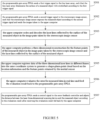
- Figure 5 illustrates a flow schematic diagram of a multi-line array laser three-dimensional scanning method based on the multi-line array laser three-dimensional scanning system above, as illustrated in Figure 5 , comprising:
- the method further comprises a step that is not illustrated in Figure 5 : S500, the programmable gate array FPGA receives a preset exposure time and a preset pulse trigger signal sent by the upper computer, sends the first trigger signal to the line laser array according to the preset pulse trigger signal, and sends the second trigger signal to the stereoscopic image sensor according to the preset exposure time.
- FIG. 6 An overall realization process of the multi-line array laser three-dimensional scanning method of the present embodiment is illustrated in Figure 6 : at S601, the upper computer controls FPGA 101, visual-inertial hybrid sensor 102 (stereoscopic image sensor 102A and inertial sensor 102B) and the upper computer to start to enter working status; at S602, FPGA 101 sends a trigger signal to control the optical elements to strobe and control the stereoscopic image sensor 102A to start collecting image pairs with exposure, meanwhile to control the inertial sensor 102B to obtain the real-time location information; at S603, the inertial sensor 102B sends the real-time location information to the upper computer, and the stereoscopic image sensor 102A sends the collected image pairs to the upper computer; at S604, the upper computer decodes and marks the laser lines by the coding and decoding function of the laser line array, so as to identify the laser plane number for each segment of the laser lines on the images; at S605, the upper computer also makes a three-dimensional reconstruction for the
- the portable multi-line array laser three-dimensional scanning device is mainly composed of programmable gate array FPGA 101, visual-inertial hybrid sensor 102 (including stereoscopic image sensor 102A and inertial sensor 102B), line laser array 103 and error feedback controller 104.
- the line laser array 103 emits a set of laser planes, which project on the surface the measured object 501 to form a set of laser line array 502.
- the circular mark point 503 is a manual mark commonly used in optical three-dimensional scanning, for registering and stitching the data under multiple scans.
- the scanning efficiency of the system above is significantly improved. Compared to single laser line scanning in the prior art, the data reconstruction rate is increased multiply by employing laser line array patterns. If the number of laser lines in an array is n, the amount of data reconstructed per unit time is n times that of single line scanning, that is, in the case where the scanning for the same amount of data is completed, the scanning time of laser line array is only 1/n of that of single line scanning. For example, the scanning efficiency of an array composed of 6 line lasers is about 6 times that of single line scanning, and the scanning time is shortened by 5/6.
- the device cost is significantly decreased.
- the process of specially customized multi-line laser generator is complex, and its technology is monopolized by only a few companies, thus the cost is very high, typically, a laser of such laser scanning device costs tens of thousands RMB; however, if employing a single laser array, the cost of a laser array with the same amount of laser lines is only several hundreds of RMB, that is, the cost of the lasers part is saved by more than 95/100, and the cost of the entire scanning device is decreased by about 2/3 accordingly.
- the service life is significantly increased. Limited by the processing speed of the image collection sensor, the effective exposure time of an image occupies about 1/10 of the total scanning time. Therefore, under the continuous scanning mode in the prior art, the main optical LED components (such as laser LED, etc.) have up to 9/10 ineffective working time. However, after employing a pulse stroboscopic scanning, the ratio of ineffective working time of the main optical LED components is reduced from 9/10 to 0. According to the nominal parameters of LED, it is estimated that the service life is increased by 10 times, the energy consumption is significantly reduced, the heat dissipation is almost negligible, meanwhile the design and manufacturing costs of heat dissipation structure is eliminated.
- the nominal parameters of LED it is estimated that the service life is increased by 10 times, the energy consumption is significantly reduced, the heat dissipation is almost negligible, meanwhile the design and manufacturing costs of heat dissipation structure is eliminated.
- the scanning erroneous stitching rate is decreased, the reliability is improved.
- employing visual-inertial hybrid sensor locating technology improves the reliability of feature points matching, avoids the wrong matching of optical features due to geometric similarity, thereby improving the correct rate of the stitching and registration of scanning data.
- the erroneous stitching rate which occurs in the single optical feature locating technology is about 50%, whereas the number of erroneous stitching that occurs in hybrid sensor locating technology is 0.
- the scanning accuracy is significantly improved. According to the internationally authoritative German VDI-2634 optical three-dimensional measuring device accuracy testing standards, it is tested that after employing error evaluation and feedback control technology, the laser scanning accuracy is improved from 0.1mm to 0.03mm, which is about 3 times the original scanning accuracy.
Landscapes
- Physics & Mathematics (AREA)
- General Physics & Mathematics (AREA)
- Engineering & Computer Science (AREA)
- Computer Vision & Pattern Recognition (AREA)
- Radar, Positioning & Navigation (AREA)
- Remote Sensing (AREA)
- Automation & Control Theory (AREA)
- Human Computer Interaction (AREA)
- Multimedia (AREA)
- Signal Processing (AREA)
- Length Measuring Devices By Optical Means (AREA)
- Theoretical Computer Science (AREA)
Claims (13)
- Dreidimensionales Mehr-Linien-Array-Laserscansystem, dadurch gekennzeichnet, dass das System Folgendes umfasst:ein dreidimensionales Mehr-Linien-Array-Laserscangerät, umfassend ein programmierbares Gate-Array-FPGA (101), mindestens einen stereoskopischen Bildsensor (102A), einen Trägheitssensor (102B), ein Linienlaser-Array (103) und eine Fehlerrückkopplungssteuerung (104), wobei das programmierbare Gate-Array-FPGA jeweils mit dem stereoskopischen Bildsensor, dem Trägheitssensor, dem Linienlaser-Array und der Fehlerrückkopplungssteuerung gekoppelt ist; undein oberer Computer (105) mit dem programmierbaren Gate-Array-FPGA, dem stereoskopischen Bildsensor bzw. dem Trägheitssensor gekoppelt ist; wobeidas programmierbare Gate-Array-FPGA so konfiguriert ist, dass es ein erstes Auslösesignal an das Linienlaser-Array sendet, so dass das Linienlaser-Array eine Oberfläche eines zu messenden Objekts mit Stroboskoplicht entsprechend dem ersten Auslösesignal beleuchtet;das programmierbare Gate-Array-FPGA außerdem so konfiguriert ist, dass es ein zweites Auslösesignal an den stereoskopischen Bildsensor sendet, so dass der stereoskopische Bildsensor entsprechend dem zweiten Auslösesignal Belichtungsaufnahmen für das Objekt durchführt und aufgenommene Bildpaare an den oberen Computer sendet;das programmierbare Gate-Array-FPGA außerdem so konfiguriert ist, dass es ein drittes Auslösesignal an den Trägheitssensor sendet, so dass der Trägheitssensor Standortinformationen des dreidimensionalen Laserscangeräts mit mehreren Linienarrays gemäß dem dritten Auslösesignal an den oberen Computer sendet;der obere Computer weiterhin dazu konfiguriert ist, eine Echtzeit-Fehlerbewertung für gemessene Daten durchzuführen und ein Bewertungsergebnis an das programmierbare Gate-Array-FPGA zurückzugeben, wobei die Fehlerbewertung den Unterschied zwischen einem Arbeitsabstand und einer Schärfentiefe des dreidimensionalen Mehr-Linien-Array-Laserscangeräts angibt;das programmierbare Gate-Array FPGA ferner konfiguriert ist, um entsprechend dem Auswertungsergebnis ein Steuersignal an die Fehlerrückkopplungssteuerung zu senden und einen Abstand zwischen dem dreidimensionalen Laserscangerät und dem gemessenen Objekt entsprechend dem Bewertungsergebnis anzupassen, nachdem das Bewertungsergebnis vom oberen Computer zurückgemeldet wurde;der obere Computer so konfiguriert ist, dass er Laserlinien in den vom stereoskopischen Bildsensor aufgenommenen Bildpaaren kodiert und dekodiert;der obere Computer ferner so konfiguriert ist, dass er eine dreidimensionale Rekonstruktion für Merkmalspunkte in den Bildpaaren des Objekts und den von der Oberfläche des Objekts reflektierten Laserlinien durchführt;der obere Computer ferner so konfiguriert ist, dass er Daten der dreidimensionalen Laserlinien in verschiedenen Rahmen im gleichen Koordinatensystem registriert, um eine Form-Ebenen-Punktwolke basierend auf den Standortinformationen und den vom Trägheitssensor zurückgegebenen Merkmalspunkten zu erzeugen; undwobei der Arbeitsabstand einen durchschnittlichen Abstand von Raumkoordinaten aller Merkmalspunkte der dreidimensionalen Rekonstruktion zum Mittelpunkt einer Verbindung der Koordinaten optischer Zentren des mindestens einen stereoskopischen Bildsensors des dreidimensionalen Mehr-Linien-Array-Laserscangeräts umfasst.
- System nach Anspruch 1, dadurch gekennzeichnet, dass das programmierbare Gate-Array-FPGA weiterhin konfiguriert ist, um ein voreingestelltes Impulsauslösesignal und eine voreingestellte Belichtungszeit zu empfangen, die vom oberen Computer gesendet werden und das erste Auslösesignal an das Linienlaser-Array zu senden und das dritte Auslösesignal jeweils entsprechend dem voreingestellten Impulsauslösesignal an den Inertialsensor zu übertragen und das zweite Auslösesignal entsprechend der voreingestellten Belichtungszeit an den stereoskopischen Bildsensor zu senden.
- System nach Anspruch 1, dadurch gekennzeichnet, dass die Fehlerrückkopplungssteuerung (104) konfiguriert ist, um das vom programmierbaren Gate-Array-FPGA (101) gesendete Steuersignal zu empfangen und eine dem Steuersignal entsprechende Anzeigeleuchte auszugeben.
- System nach Anspruch 3, dadurch gekennzeichnet, dass die Fehlerrückkopplungssteuerung (104) ein farbwechselndes LED-Licht ist, das die Lichter enthält, die aus den drei Primärfarben Rot, Grün und Blau kombiniert sind.
- System nach Anspruch 1, dadurch gekennzeichnet, dass der stereoskopische Bildsensor (102A) ein Multivision-Bildsensor ist, der aus zwei oder mehr optischen Kameras besteht.
- System nach Anspruch 1, dadurch gekennzeichnet, dass der stereoskopische Bildsensor (102A) mit einer Beleuchtungseinrichtung ausgestattet ist.
- System nach Anspruch 6, dadurch gekennzeichnet, dass die Beleuchtungszeit der Beleuchtungseinrichtung mit der Belichtungszeit des stereoskopischen Sensors synchronisiert ist.
- System nach Anspruch 1, dadurch gekennzeichnet, dass das Linienlaser-Array eine Vielzahl von Linienlasern umfasst, die in einer Matrixanordnung angeordnet sind.
- System nach Anspruch 1, dadurch gekennzeichnet, dass der obere Computer (105) so konfiguriert ist, dass er die Merkmalspunkte verfolgt und Daten der dreidimensionalen Laserlinien durch Verfolgen der gleichnamigen Merkmalspunkte zwischen benachbarten Zeitrahmen in verschiedenen Rahmen im gleichen Koordinatensystem registriert.
- System nach Anspruch 1, dadurch gekennzeichnet, dass der obere Computer (105) außerdem dazu konfiguriert ist, den Abstand zwischen dem dreidimensionalen Laserscangerät und dem gemessenen Objekt (501) in Echtzeit auszuwerten und das Bewertungsergebnis an den programmierbaren Gate-Array-FPGA (101) zurückzugeben, wenn der Abstand den voreingestellten Abstand überschreitet.
- System nach einem der Ansprüche 1 bis 10, dadurch gekennzeichnet, dass der obere Computer (105) ferner mit einer Kommunikationsschnittstelle zur Kommunikation mit einem Steuergerät ausgestattet ist, das mit dem Steuergerät gekoppelt ist, so dass das Steuergerät den Abstand zwischen der dreidimensionalen Mehr-Linien-Array-Laserscangerät und dem gemessenen Objekt einstellt.
- Verfahren zum dreidimensionalen Mehr-Linien-Array-Laserscannen basierend auf dem dreidimensionalen Mehr-Linien-Array-Laserscansystem nach einem der Ansprüche 1 bis 11, dadurch gekennzeichnet, dass das Verfahren Folgendes umfasst:das programmierbare Gate-Array-FPGA ein erstes Auslösesignal an das Linienlaser-Array sendet,so dass das Linienlaser-Array die Oberfläche eines Messobjekts entsprechend dem ersten Auslösesignal mit Stroboskoplicht beleuchtet;das programmierbare Gate-Array-FPGA (101) ein zweites Auslösesignal an den stereoskopischen Bildsensor sendet, so dass der stereoskopische Bildsensor das gemessene Objekt gemäß dem zweiten Auslösesignal belichtet und die aufgenommenen Bilder an den oberen Computer sendet;der obere Computer (105) die von der Oberfläche des gemessenen Objekts reflektierten Laserlinien in den vom stereoskopischen Bildsensor aufgenommenen Bildpaaren kodiert und dekodiert;der obere Computer eine dreidimensionale Rekonstruktion für die Merkmalspunkte des Messobjekts (501) in den vom stereoskopischen Bildsensor aufgenommenen Bildpaaren und den von der Oberfläche des Messobjekts reflektierten Laserlinien durchführt;der obere Computer Daten der dreidimensionalen Laserlinien in verschiedenen Rahmen im gleichen Koordinatensystem registriert, um eine Form-Ebenen-Punktwolke basierend auf den Standortinformationen und den vom Trägheitssensor zurückgegebenen Merkmalspunkten zu erzeugen;der obere Computer (105) den Fehler für gemessene Daten in Echtzeit auswertet und das Bewertungsergebnis an den FPGA mit programmierbarem Gate-Array zurückgibt;das programmierbare Gate-Array-FPGA (101) ein Steuersignal an die Fehlerrückkopplungssteuerung (104) sendet und den Arbeitsabstand zwischen dem dreidimensionalen Laserscangerät und dem gemessenen Objekt entsprechend dem Bewertungsergebnis nach Erhalt des vom oberen Computer rückgemeldeten Bewertungsergebnisses anpasst, wobei der Arbeitsabstand einen durchschnittlichen Abstand von Raumkoordinaten der Merkmalspunkte der dreidimensionalen Rekonstruktion zu einem Mittelpunkt einer Verbindung der Koordinaten optischer Zentren des mindestens einen stereoskopischen Bildsensors des dreidimensionalen Mehr-Linien-Array-Laserscangeräts umfasst.
- Verfahren nach Anspruch 12, dadurch gekennzeichnet, dass das Verfahren, bevor das programmierbare Gate-Array-FPGA das erste Auslösesignal an das Linienlaser-Array sendet, ferner Folgendes umfasst:
der programmierbare Gate-Array-FPGA eine voreingestellte Belichtungszeit und ein voreingestelltes Impulsauslösesignal empfängt, die vom oberen Computer gesendet werden, das ersten Auslösesignal an das Linienlaser-Array sendet und das dritte Auslösesignal an den Trägheitssensor jeweils entsprechend dem voreingestellten Impulsauslösesignal überträgt und das zweite Auslösesignal an den stereoskopischen Bildsensor gemäß der voreingestellten Belichtungszeit sendet.
Applications Claiming Priority (2)
| Application Number | Priority Date | Filing Date | Title |
|---|---|---|---|
| CN201510574982.XA CN105222724B (zh) | 2015-09-10 | 2015-09-10 | 多线阵列激光三维扫描系统及多线阵列激光三维扫描方法 |
| PCT/CN2016/072451 WO2017041419A1 (zh) | 2015-09-10 | 2016-01-28 | 多线阵列激光三维扫描系统及多线阵列激光三维扫描方法 |
Publications (4)
| Publication Number | Publication Date |
|---|---|
| EP3348958A1 EP3348958A1 (de) | 2018-07-18 |
| EP3348958A4 EP3348958A4 (de) | 2019-10-09 |
| EP3348958B1 true EP3348958B1 (de) | 2023-08-02 |
| EP3348958C0 EP3348958C0 (de) | 2023-08-02 |
Family
ID=54991817
Family Applications (1)
| Application Number | Title | Priority Date | Filing Date |
|---|---|---|---|
| EP16843363.9A Active EP3348958B1 (de) | 2015-09-10 | 2016-01-28 | Dreidimensionales abtastsystem mit multilinien-arraylaser und dreidimensionales abtastverfahren mit multilinien-arraylaser |
Country Status (7)
| Country | Link |
|---|---|
| US (1) | US10267627B2 (de) |
| EP (1) | EP3348958B1 (de) |
| JP (1) | JP6550536B2 (de) |
| KR (1) | KR102015606B1 (de) |
| CN (1) | CN105222724B (de) |
| ES (1) | ES2961734T3 (de) |
| WO (1) | WO2017041419A1 (de) |
Families Citing this family (117)
| Publication number | Priority date | Publication date | Assignee | Title |
|---|---|---|---|---|
| CN105222724B (zh) * | 2015-09-10 | 2018-09-18 | 北京天远三维科技股份有限公司 | 多线阵列激光三维扫描系统及多线阵列激光三维扫描方法 |
| US10438036B1 (en) | 2015-11-09 | 2019-10-08 | Cognex Corporation | System and method for reading and decoding ID codes on a curved, sloped and/or annular object |
| CN106017355A (zh) * | 2016-03-22 | 2016-10-12 | 武汉武大卓越科技有限责任公司 | 一种基于线结构光的三维测量传感器 |
| CN105759280A (zh) * | 2016-05-17 | 2016-07-13 | 上海酷哇机器人有限公司 | 对人眼安全的激光三角测量系统 |
| CN106153074B (zh) * | 2016-06-20 | 2023-05-05 | 浙江大学 | 一种惯性测量组合动态导航性能的光学标定系统和方法 |
| CN108020825B (zh) * | 2016-11-03 | 2021-02-19 | 岭纬公司 | 激光雷达、激光摄像头、视频摄像头的融合标定系统及方法 |
| CN108274463B (zh) * | 2017-01-06 | 2024-03-26 | 苏州华兴致远电子科技有限公司 | 列车库检机器人和列车零部件检测方法 |
| CN107649947A (zh) * | 2017-05-02 | 2018-02-02 | 上海华太数控技术有限公司 | Cnc视觉定位系统 |
| CN106969724B (zh) * | 2017-05-09 | 2023-03-24 | 河南科技大学 | 一种自旋转十字线激光扫描的环境三维形貌感知装置 |
| CN107167118B (zh) * | 2017-06-05 | 2019-10-11 | 南京航空航天大学 | 一种基于非编码平行多线的稳定实时激光测量方法 |
| CN108317954B (zh) * | 2017-10-27 | 2020-06-12 | 广东康云多维视觉智能科技有限公司 | 一种激光引导扫描系统和方法 |
| CN107678040B (zh) * | 2017-11-03 | 2023-09-26 | 长春理工大学 | 用于车载三维成像固态激光雷达系统 |
| US10516876B2 (en) * | 2017-12-19 | 2019-12-24 | Intel Corporation | Dynamic vision sensor and projector for depth imaging |
| CN107976157A (zh) * | 2017-12-26 | 2018-05-01 | 天远三维(天津)科技有限公司 | 一种于获取物体表面三维形貌的无线手持式三维扫描设备 |
| CN108007385B (zh) * | 2017-12-31 | 2023-11-14 | 中国人民解放军陆军工程大学 | 一种大视场弹坑表面形貌成像系统及方法 |
| US10949700B2 (en) * | 2018-01-10 | 2021-03-16 | Qualcomm Incorporated | Depth based image searching |
| US10819972B2 (en) | 2018-05-03 | 2020-10-27 | Osram Sylvania Inc. | Method and apparatus for light and computer vision based dimensional metrology and 3D reconstruction |
| TWI676781B (zh) * | 2018-08-17 | 2019-11-11 | 鑑微科技股份有限公司 | 三維掃描系統 |
| CN109141236A (zh) * | 2018-08-17 | 2019-01-04 | 上海交通大学 | 基于振镜扫描的激光频闪三维视觉测量系统及方法 |
| US11029146B2 (en) * | 2018-10-18 | 2021-06-08 | Cyberoptics Corporation | Three-dimensional sensor with counterposed channels |
| CN209224071U (zh) * | 2018-11-19 | 2019-08-09 | 炬星科技(深圳)有限公司 | 机器人的传感器布局系统 |
| CN109375573A (zh) * | 2018-11-22 | 2019-02-22 | 南通科技职业学院 | 一种工业机器视觉系统图像处理方法 |
| CN109443237B (zh) * | 2018-11-30 | 2023-09-22 | 广西师范大学 | 一种远距离结构光三维测量装置 |
| CN109584288B (zh) * | 2018-12-26 | 2023-05-02 | 苏州大学 | 一种五轴系统中三维模型的重构方法及系统 |
| CN109920007B (zh) * | 2019-01-26 | 2023-04-07 | 中国海洋大学 | 基于多光谱光度立体与激光扫描的三维成像装置及方法 |
| JP7412983B2 (ja) * | 2019-02-04 | 2024-01-15 | キヤノン株式会社 | 情報処理装置、情報処理方法、及びプログラム |
| US10488185B1 (en) * | 2019-03-14 | 2019-11-26 | The Boeing Company | Methods and systems for characterizing a surface of a structural component |
| JP2020153718A (ja) * | 2019-03-18 | 2020-09-24 | 株式会社リコー | 測定装置及び造形装置 |
| GB201904072D0 (en) * | 2019-03-25 | 2019-05-08 | Secr Defence | Dazzle resilient video camera or video camera module |
| CN110153417A (zh) * | 2019-04-30 | 2019-08-23 | 大族激光科技产业集团股份有限公司 | 一种激光成型设备 |
| CN110295533A (zh) * | 2019-08-02 | 2019-10-01 | 武汉夕睿光电技术有限公司 | 一种路面移动测量装置、系统及方法 |
| JP7538221B2 (ja) | 2019-10-06 | 2024-08-21 | オルボテック リミテッド | ハイブリッド3d検査システム |
| CN110887486B (zh) * | 2019-10-18 | 2022-05-20 | 南京航空航天大学 | 一种基于激光线辅助的无人机视觉导航定位方法 |
| CN110763194B (zh) * | 2019-11-01 | 2021-11-02 | 中国矿业大学 | 一种地面三维激光扫描无标靶监测矿区地表沉陷的方法 |
| CN110930382A (zh) * | 2019-11-19 | 2020-03-27 | 广东博智林机器人有限公司 | 基于标定板特征点提取的点云拼接精度评估方法及系统 |
| CN110986904A (zh) * | 2019-12-20 | 2020-04-10 | 上海振华重工(集团)股份有限公司 | 一种自动运输车的激光器标定系统及方法 |
| US12050099B2 (en) | 2020-02-21 | 2024-07-30 | The Boeing Company | Systems and methods for determining space availability in an aircraft |
| US10996051B1 (en) | 2020-02-21 | 2021-05-04 | The Boeing Company | Systems and methods for determining space availability in an aircraft |
| CN111325796B (zh) * | 2020-02-28 | 2023-08-18 | 北京百度网讯科技有限公司 | 用于确定视觉设备的位姿的方法和装置 |
| KR102444879B1 (ko) * | 2020-03-05 | 2022-09-19 | 고려대학교 산학협력단 | 라이다(Lidar)를 이용한 실내 공간의 3차원 모델링 방법 |
| WO2021187839A1 (ko) * | 2020-03-16 | 2021-09-23 | 엘지전자 주식회사 | 포인트 클라우드 데이터 전송 장치, 전송 방법, 처리 장치 및 처리 방법 |
| US11287314B1 (en) * | 2020-03-17 | 2022-03-29 | Roof Asset Management Usa Ltd. | Method for evaluating artificial lighting of a surface |
| CN113175869A (zh) * | 2020-04-09 | 2021-07-27 | 宁波熠视科技有限公司 | 适用于大型平板类工业零件的尺寸检测设备 |
| CN111649729A (zh) * | 2020-05-16 | 2020-09-11 | 阿勒泰正元国际矿业有限公司 | 一种基于三维激光扫描的矿山采空区探测方法 |
| CN111632279B (zh) * | 2020-05-23 | 2021-12-10 | 四川中测辐射科技有限公司 | 利用多传感器进行三维射束分析仪的ssd精确调整方法 |
| CN111476705B (zh) * | 2020-05-28 | 2025-02-21 | 中国科学院空天信息创新研究院 | 主被动三维成像实时处理系统及方法 |
| US12380605B2 (en) | 2020-06-29 | 2025-08-05 | Lg Electronics Inc. | Point cloud data transmission device, transmission method, processing device, and processing method |
| CN111854601B (zh) * | 2020-07-17 | 2023-03-28 | 湖南华曙高科技股份有限公司 | 用于多激光多扫描系统的校准装置及其校准方法 |
| US11763473B2 (en) | 2020-07-23 | 2023-09-19 | Zhejiang Hanchine Ai Tech. Co., Ltd. | Multi-line laser three-dimensional imaging method and system based on random lattice |
| CN111854642B (zh) * | 2020-07-23 | 2021-08-10 | 浙江汉振智能技术有限公司 | 基于随机点阵的多线激光三维成像方法及系统 |
| CN111860544B (zh) * | 2020-07-28 | 2024-05-17 | 杭州优链时代科技有限公司 | 一种投影辅助衣物特征提取方法及系统 |
| CN111982021A (zh) * | 2020-07-29 | 2020-11-24 | 江苏大学 | 一种船舶曲板成形便携式三维视觉检测系统及方法 |
| CN112082513A (zh) * | 2020-09-09 | 2020-12-15 | 易思维(杭州)科技有限公司 | 一种多激光阵列三维扫描系统及方法 |
| WO2022060176A1 (ko) * | 2020-09-17 | 2022-03-24 | 엘지전자 주식회사 | 포인트 클라우드 데이터 전송 방법, 포인트 클라우드 데이터 전송 장치, 포인트 클라우드 데이터 수신 방법 및 포인트 클라우드 데이터 수신 장치 |
| CN112113505B (zh) * | 2020-09-23 | 2022-02-01 | 华中科技大学鄂州工业技术研究院 | 一种基于线结构光的便携扫描测量装置及方法 |
| CN112254650B (zh) * | 2020-09-25 | 2022-03-01 | 武汉科技大学 | 激光测距式动态检测皮带跑偏系统 |
| CN112284294A (zh) * | 2020-09-27 | 2021-01-29 | 浙江大学 | 一种水下多波段交叉线阵激光三维扫描系统 |
| US20230388557A1 (en) * | 2020-10-07 | 2023-11-30 | Lg Electronics Inc. | Point cloud data transmission device, point cloud data transmission method, point cloud data reception device, and point cloud data reception method |
| US12361598B2 (en) | 2020-10-16 | 2025-07-15 | Lg Electronics Inc. | Point cloud data transmission method, point cloud data transmission device, point cloud data reception method, and point cloud data reception device |
| CN112307562B (zh) * | 2020-10-30 | 2022-03-01 | 泉州装备制造研究所 | 综合热变形与重力变形的大型飞机上复杂部件的装配方法 |
| CN112489110A (zh) * | 2020-11-25 | 2021-03-12 | 西北工业大学青岛研究院 | 一种水下动态场景光学混合三维成像方法 |
| CN112648938B (zh) * | 2020-12-11 | 2025-07-04 | 南京航空航天大学 | 大尺寸平板类模具空间姿态的分布式精密测量装置及方法 |
| CN112781470B (zh) * | 2020-12-24 | 2022-08-16 | 中广核核电运营有限公司 | U型槽多维度间隙测量方法及系统 |
| CN112833816A (zh) * | 2020-12-31 | 2021-05-25 | 武汉中观自动化科技有限公司 | 一种标志点定位与智能反向定位混合的定位方法和系统 |
| CN112819774A (zh) * | 2021-01-28 | 2021-05-18 | 上海工程技术大学 | 基于三维重建技术的大型构件外形误差检测方法及其应用 |
| CN112958958B (zh) * | 2021-02-08 | 2023-03-21 | 西安知象光电科技有限公司 | 一种mems微镜面扫描与线扫描混合的激光焊缝扫描装置及扫描方法 |
| CN113029041B (zh) * | 2021-04-02 | 2022-11-01 | 扬州大学 | 一种多条激光线错位插补的测量方法 |
| EP4075095A1 (de) * | 2021-04-14 | 2022-10-19 | Medit Corp. | Dreidimensionales abtastsystem und verfahren zu dessen steuerung |
| CN113390362B (zh) * | 2021-05-26 | 2023-02-28 | 武汉钢铁有限公司 | 一种用于激光线性扫描的高精度自适应平台 |
| CN113531018B (zh) * | 2021-06-23 | 2022-09-06 | 中国矿业大学 | 一种基于激光网格的矿井提升机制动盘故障监测系统及方法 |
| CN113390357B (zh) * | 2021-07-08 | 2022-06-07 | 南京航空航天大学 | 一种基于双目多线结构光的铆钉齐平度测量方法 |
| JP7707700B2 (ja) * | 2021-07-08 | 2025-07-15 | 日本電気株式会社 | 分析装置、データ生成方法、及びプログラム |
| CN113624142B (zh) * | 2021-07-26 | 2022-12-13 | 成都飞机工业(集团)有限责任公司 | 一种飞机装配紧固件凹凸量检测方法 |
| JP7682729B2 (ja) * | 2021-07-30 | 2025-05-26 | 日鉄テックスエンジ株式会社 | 長尺物の形状測定システム及び形状測定方法 |
| CN113640824A (zh) * | 2021-08-20 | 2021-11-12 | 西安外事学院 | 一种光摄一体式控制系统及控制方法 |
| CN113983953A (zh) * | 2021-09-29 | 2022-01-28 | 江苏兴邦能源科技有限公司 | 基于三维建模技术的燃料电池双极板测试系统及方法 |
| CN114295046B (zh) * | 2021-11-30 | 2023-07-11 | 宏大爆破工程集团有限责任公司 | 一种爆堆形态综合评价方法及系统、电子设备、存储介质 |
| CN114264249B (zh) * | 2021-12-14 | 2023-06-16 | 中国石油大学(华东) | 深孔狭小内腔三维测量系统及方法 |
| CN114199132B (zh) * | 2021-12-16 | 2024-02-27 | 上海应用技术大学 | 一种基于机器视觉的激光三维扫描仪及扫描方法 |
| CN116408575B (zh) * | 2021-12-31 | 2024-06-04 | 广东美的白色家电技术创新中心有限公司 | 局部扫描、消除工件反光干扰的方法、装置和系统 |
| CN114440792A (zh) * | 2022-01-11 | 2022-05-06 | 重庆固高科技长江研究院有限公司 | 多线激光传感的封闭布局结构、扫描拼接及涂胶扫描方法 |
| CN114485479B (zh) * | 2022-01-17 | 2022-12-30 | 吉林大学 | 基于双目相机和惯性导航的结构光扫描测量方法及系统 |
| CN114596583B (zh) * | 2022-03-04 | 2025-08-29 | 浙江星链数据科技有限公司 | 一种手持3d扫描传感系统、方法及手持3d扫描装置 |
| CN114719775B (zh) * | 2022-04-06 | 2023-08-29 | 新拓三维技术(深圳)有限公司 | 一种运载火箭舱段自动化形貌重建方法及系统 |
| CN114620091B (zh) * | 2022-04-11 | 2025-01-14 | 南京拓控信息科技股份有限公司 | 一种基于三维信息的列车车轮不圆度检测方法 |
| CN114820489B (zh) * | 2022-04-15 | 2022-10-25 | 北京昆迈医疗科技有限公司 | 一种基于空间标记点的opm阵列快速光学扫描定位方法 |
| CN114820939B (zh) * | 2022-04-28 | 2025-12-23 | 杭州海康机器人股份有限公司 | 一种图像重建方法、装置及设备 |
| CN114779465B (zh) * | 2022-06-23 | 2022-09-13 | 杭州灵西机器人智能科技有限公司 | 一种双线激光扫描系统和方法 |
| ES3040803T3 (en) * | 2022-06-29 | 2025-11-05 | Airbus Operations Gmbh | Method and system for detecting the properties of a section of an aircraft |
| CN115243022B (zh) * | 2022-08-22 | 2024-03-05 | 周口师范学院 | 一种激光投影互动展示系统 |
| CN115511688B (zh) * | 2022-11-04 | 2023-03-10 | 思看科技(杭州)股份有限公司 | 数据处理设备和三维扫描系统 |
| CN115930835B (zh) * | 2022-12-19 | 2026-02-24 | 上海交通大学 | 一种基于数字化样箱的曲板成形质量评价方法和系统 |
| CN115792869B (zh) * | 2022-12-27 | 2025-02-18 | 江苏集萃智能光电系统研究所有限公司 | 一种2d面阵相机与线激光3d传感器联合标定方法及装置 |
| CN115830181B (zh) * | 2023-01-04 | 2023-05-09 | 深圳市先地图像科技有限公司 | 一种用于激光成像的图像处理方法、装置及相关设备 |
| CN116299502A (zh) * | 2023-02-03 | 2023-06-23 | 深圳市朗驰欣创科技股份有限公司 | 一种融合视觉信息的3d激光雷达定位方法及系统 |
| CN116592786A (zh) * | 2023-04-04 | 2023-08-15 | 思看科技(杭州)股份有限公司 | 三维数据获取方法、装置、计算机设备和存储介质 |
| CN116206069B (zh) * | 2023-04-28 | 2023-10-13 | 思看科技(杭州)股份有限公司 | 三维扫描中的图像数据处理方法、装置和三维扫描仪 |
| CN116756893B (zh) * | 2023-06-16 | 2024-01-05 | 深圳讯道实业股份有限公司 | 应用于工矿控制系统的输配电电缆布设及控制方法 |
| CN116760931B (zh) * | 2023-06-20 | 2024-01-30 | 深圳市光太科技有限公司 | 一种提高线扫相机拍摄精度的方法与装置 |
| CN116781837B (zh) * | 2023-08-25 | 2023-11-14 | 中南大学 | 一种自动化激光三维扫描系统 |
| CN117190983B (zh) * | 2023-09-05 | 2024-04-26 | 湖南天桥嘉成智能科技有限公司 | 一种隧道超欠开挖检测系统、方法、设备及存储介质 |
| CN117237230B (zh) * | 2023-11-09 | 2024-03-22 | 武汉中观自动化科技有限公司 | 激光线及标志点识别方法及系统 |
| CN118224977B (zh) * | 2024-03-29 | 2026-01-09 | 天津大学 | 一种多传感器三维测量数据匹配方法 |
| CN118038778B (zh) * | 2024-04-12 | 2024-06-25 | 北京数字光芯集成电路设计有限公司 | 一种基于线阵光源的光学扫描方法 |
| CN118729941A (zh) * | 2024-06-28 | 2024-10-01 | 思看科技(杭州)股份有限公司 | 三维扫描方法、三维数据处理方法和三维扫描系统 |
| CN118784816B (zh) * | 2024-08-29 | 2025-04-22 | 深圳市金沃德科技有限公司 | 基于多摄像头拍摄的3d影像生成方法及系统 |
| CN119338978B (zh) * | 2024-09-02 | 2025-08-15 | 深圳技术大学 | 基于激光-多面反射转镜的三维重建方法、系统及介质 |
| CN119245515B (zh) * | 2024-12-03 | 2025-02-18 | 东莞市兆丰精密仪器有限公司 | 一种基于线激光连续触发扫描的扫描速度处理方法及系统 |
| CN119289864B (zh) * | 2024-12-10 | 2025-04-01 | 武汉中观自动化科技有限公司 | 一种三维点云采集方法和结构光扫描设备 |
| CN119714118B (zh) * | 2024-12-27 | 2025-11-18 | 上海航天技术基础研究所 | 一种大尺寸曲面构件三维形貌快速测量装置和方法及缺陷识别方法 |
| CN119468923B (zh) * | 2025-01-15 | 2025-06-17 | 思看科技(杭州)股份有限公司 | 扫描控制方法、扫描控制装置、扫描控制系统和存储介质 |
| CN120142296A (zh) * | 2025-02-06 | 2025-06-13 | 哈尔滨拓博科技有限公司 | 一种面向非规则钢材表面检测的装置及其运行方法 |
| CN120107482B (zh) * | 2025-02-24 | 2025-09-16 | 中交智高(浙江)科技发展有限公司 | 一种基于人工智能的隧道施工进度自动化采集方法及系统 |
| CN119762683B (zh) * | 2025-03-03 | 2025-06-10 | 江苏濠汉信息技术有限公司 | 十字激光进行输电线路三维重建的方法及装置 |
| CN119762722B (zh) * | 2025-03-07 | 2025-07-15 | 先临三维科技股份有限公司 | 转站扫描的数据拼接方法及相关设备、转站扫描系统 |
| CN119915182B (zh) * | 2025-04-01 | 2025-07-04 | 成都纵横通达信息工程有限公司 | 一种基于三维扫描的炮点定位方法 |
| CN119991767B (zh) * | 2025-04-09 | 2025-07-29 | 重庆星网网络系统研究院有限公司 | 一种光斑检测方法、装置、电子设备及存储介质 |
Citations (1)
| Publication number | Priority date | Publication date | Assignee | Title |
|---|---|---|---|---|
| CN102589476B (zh) * | 2012-02-13 | 2014-04-02 | 天津大学 | 高速扫描整体成像三维测量方法 |
Family Cites Families (31)
| Publication number | Priority date | Publication date | Assignee | Title |
|---|---|---|---|---|
| JPH07260444A (ja) * | 1994-03-24 | 1995-10-13 | Nippon Avionics Co Ltd | 光切断法による対象物の三次元計測方法およびその装置 |
| US6377700B1 (en) * | 1998-06-30 | 2002-04-23 | Intel Corporation | Method and apparatus for capturing stereoscopic images using image sensors |
| WO2003060424A1 (en) * | 2002-01-18 | 2003-07-24 | Mv Research Limited | A machine vision system |
| US7196300B2 (en) * | 2003-07-18 | 2007-03-27 | Rudolph Technologies, Inc. | Dynamic focusing method and apparatus |
| CN1203292C (zh) * | 2003-08-15 | 2005-05-25 | 清华大学 | 测量物体三维表面轮廊的方法 |
| JP3991040B2 (ja) * | 2003-08-20 | 2007-10-17 | 独立行政法人科学技術振興機構 | 三次元計測装置及び三次元計測方法 |
| US7375826B1 (en) * | 2004-09-23 | 2008-05-20 | The United States Of America As Represented By The Administrator Of The National Aeronautics And Space Administration (Nasa) | High speed three-dimensional laser scanner with real time processing |
| WO2011000435A1 (en) * | 2009-07-03 | 2011-01-06 | Leica Geosystems Ag | Apparatus for generating three-dimensional image of object |
| KR101126626B1 (ko) * | 2010-03-02 | 2012-03-26 | 한국과학기술원 | 광역 3차원 복원을 위한 시스템 및 방법 |
| JP2012058076A (ja) * | 2010-09-09 | 2012-03-22 | 3D Media Co Ltd | 3次元計測装置及び3次元計測方法 |
| DE102010049672B3 (de) * | 2010-10-20 | 2012-02-16 | Technische Universität Dresden | Laser-Doppler-Linien-Distanzsensor zur dreidimensionalen Formvermessung bewegter Festkörper |
| KR101706093B1 (ko) * | 2010-11-30 | 2017-02-14 | 삼성전자주식회사 | 3차원 좌표 추출 시스템 및 그 방법 |
| US9402036B2 (en) * | 2011-10-17 | 2016-07-26 | Rudolph Technologies, Inc. | Scanning operation with concurrent focus and inspection |
| CN102607462B (zh) * | 2012-03-26 | 2014-02-12 | 武汉迅能光电科技有限公司 | 一种三维激光扫描信号同步及修正方法 |
| US9091535B2 (en) * | 2012-05-22 | 2015-07-28 | Korea Institute Of Industrial Technology | 3D scanning system and method of obtaining 3D image |
| KR20140049361A (ko) * | 2012-10-17 | 2014-04-25 | 한국과학기술원 | 다중 센서 시스템, 이를 이용하는 3차원 월드 모델링 장치 및 방법 |
| EP2972478B1 (de) * | 2013-03-15 | 2020-12-16 | Uatc, Llc | Verfahren, systeme und vorrichtungen für eine multisensorische stereovision für robotersysteme |
| KR101458696B1 (ko) * | 2013-04-19 | 2014-11-05 | 이기창 | 고속 전자식 3차원 레이저 스캐너 장치 |
| JP2015045587A (ja) * | 2013-08-28 | 2015-03-12 | 株式会社キーエンス | 三次元画像処理装置、三次元画像処理装置の状態変化判定方法、三次元画像処理装置の状態変化判定プログラム及びコンピュータで読み取り可能な記録媒体並びに記録した機器 |
| CN103604366B (zh) * | 2013-11-06 | 2016-03-02 | 深圳市华星光电技术有限公司 | 用于检测误差并引导误差校正的系统及方法 |
| JP6230434B2 (ja) * | 2014-01-31 | 2017-11-15 | 株式会社キーエンス | 画像検査装置、画像検査方法及び画像検査プログラム並びにコンピュータで読み取り可能な記録媒体 |
| KR101604037B1 (ko) * | 2014-05-09 | 2016-03-16 | 한국건설기술연구원 | 카메라와 레이저 스캔을 이용한 3차원 모델 생성 및 결함 분석 방법 |
| CN104165600B (zh) * | 2014-07-03 | 2016-10-05 | 杭州鼎热科技有限公司 | 一种无线手持3d激光扫描系统 |
| US10043282B2 (en) * | 2015-04-13 | 2018-08-07 | Gerard Dirk Smits | Machine vision for ego-motion, segmenting, and classifying objects |
| US10122998B2 (en) * | 2015-04-30 | 2018-11-06 | Seiko Epson Corporation | Real time sensor and method for synchronizing real time sensor data streams |
| US9964398B2 (en) * | 2015-05-06 | 2018-05-08 | Faro Technologies, Inc. | Three-dimensional measuring device removably coupled to robotic arm on motorized mobile platform |
| US9903934B2 (en) * | 2015-06-30 | 2018-02-27 | Faro Technologies, Inc. | Apparatus and method of measuring six degrees of freedom |
| CN104990518A (zh) * | 2015-07-13 | 2015-10-21 | 深圳市易尚展示股份有限公司 | 一种基于fpga的三维扫描控制装置和方法 |
| CN105203046B (zh) * | 2015-09-10 | 2018-09-18 | 北京天远三维科技股份有限公司 | 多线阵列激光三维扫描系统及多线阵列激光三维扫描方法 |
| CN105222724B (zh) * | 2015-09-10 | 2018-09-18 | 北京天远三维科技股份有限公司 | 多线阵列激光三维扫描系统及多线阵列激光三维扫描方法 |
| EP3397921A1 (de) * | 2015-12-30 | 2018-11-07 | Faro Technologies, Inc. | Registrierung von auf den inneren und äusseren teilen eines objekts gemessenen dreidimensionalen koordinaten |
-
2015
- 2015-09-10 CN CN201510574982.XA patent/CN105222724B/zh active Active
-
2016
- 2016-01-28 EP EP16843363.9A patent/EP3348958B1/de active Active
- 2016-01-28 ES ES16843363T patent/ES2961734T3/es active Active
- 2016-01-28 KR KR1020177032099A patent/KR102015606B1/ko active Active
- 2016-01-28 JP JP2018515340A patent/JP6550536B2/ja active Active
- 2016-01-28 WO PCT/CN2016/072451 patent/WO2017041419A1/zh not_active Ceased
- 2016-01-28 US US15/741,238 patent/US10267627B2/en active Active
Patent Citations (1)
| Publication number | Priority date | Publication date | Assignee | Title |
|---|---|---|---|---|
| CN102589476B (zh) * | 2012-02-13 | 2014-04-02 | 天津大学 | 高速扫描整体成像三维测量方法 |
Also Published As
| Publication number | Publication date |
|---|---|
| CN105222724A (zh) | 2016-01-06 |
| US10267627B2 (en) | 2019-04-23 |
| KR20170135914A (ko) | 2017-12-08 |
| CN105222724B (zh) | 2018-09-18 |
| JP6550536B2 (ja) | 2019-07-24 |
| EP3348958A1 (de) | 2018-07-18 |
| ES2961734T3 (es) | 2024-03-13 |
| EP3348958A4 (de) | 2019-10-09 |
| EP3348958C0 (de) | 2023-08-02 |
| KR102015606B1 (ko) | 2019-08-28 |
| JP2018516377A (ja) | 2018-06-21 |
| US20180180408A1 (en) | 2018-06-28 |
| WO2017041419A1 (zh) | 2017-03-16 |
Similar Documents
| Publication | Publication Date | Title |
|---|---|---|
| EP3348958B1 (de) | Dreidimensionales abtastsystem mit multilinien-arraylaser und dreidimensionales abtastverfahren mit multilinien-arraylaser | |
| CN105203046B (zh) | 多线阵列激光三维扫描系统及多线阵列激光三维扫描方法 | |
| US20220155060A1 (en) | Triangulation scanner with blue-light projector | |
| US11587252B2 (en) | Positioning method and system combining mark point positioning and intelligent reverse positioning | |
| US10060722B2 (en) | Articulated arm coordinate measurement machine having a 2D camera and method of obtaining 3D representations | |
| EP3531066B1 (de) | Dreidimensionales abtastverfahren mit einer vielzahl von lasern mit unterschiedlichen wellenlängen und scanner | |
| US8832954B2 (en) | Coordinate measurement machines with removable accessories | |
| US10281259B2 (en) | Articulated arm coordinate measurement machine that uses a 2D camera to determine 3D coordinates of smoothly continuous edge features | |
| US9628775B2 (en) | Articulated arm coordinate measurement machine having a 2D camera and method of obtaining 3D representations | |
| TWI460394B (zh) | 三維影像量測裝置 | |
| JP5816773B2 (ja) | 取り外し可能なアクセサリーを備える座標測定マシン | |
| US20150070468A1 (en) | Use of a three-dimensional imager's point cloud data to set the scale for photogrammetry | |
| US20140192187A1 (en) | Non-contact measurement device | |
| CN109900221A (zh) | 一种手持式三维扫描系统 | |
| CN107421462A (zh) | 基于线激光扫描的物体三维轮廓测量系统 | |
| CN110044266B (zh) | 基于散斑投影的摄影测量系统 | |
| CN104034729A (zh) | 用于电路板分选的五维成像系统及其成像方法 | |
| WO2016044014A1 (en) | Articulated arm coordinate measurement machine having a 2d camera and method of obtaining 3d representations | |
| EP3385661B1 (de) | Gelenkarm-koordinatenmessmaschine, die mit einer 2d-kamera 3d-koordinaten von glatten, kontinuierlichen kantenmerkmalen ermittelt |
Legal Events
| Date | Code | Title | Description |
|---|---|---|---|
| STAA | Information on the status of an ep patent application or granted ep patent |
Free format text: STATUS: THE INTERNATIONAL PUBLICATION HAS BEEN MADE |
|
| PUAI | Public reference made under article 153(3) epc to a published international application that has entered the european phase |
Free format text: ORIGINAL CODE: 0009012 |
|
| STAA | Information on the status of an ep patent application or granted ep patent |
Free format text: STATUS: REQUEST FOR EXAMINATION WAS MADE |
|
| 17P | Request for examination filed |
Effective date: 20171207 |
|
| AK | Designated contracting states |
Kind code of ref document: A1 Designated state(s): AL AT BE BG CH CY CZ DE DK EE ES FI FR GB GR HR HU IE IS IT LI LT LU LV MC MK MT NL NO PL PT RO RS SE SI SK SM TR |
|
| AX | Request for extension of the european patent |
Extension state: BA ME |
|
| DAV | Request for validation of the european patent (deleted) | ||
| DAX | Request for extension of the european patent (deleted) | ||
| A4 | Supplementary search report drawn up and despatched |
Effective date: 20190905 |
|
| RIC1 | Information provided on ipc code assigned before grant |
Ipc: G01B 11/25 20060101AFI20190830BHEP |
|
| STAA | Information on the status of an ep patent application or granted ep patent |
Free format text: STATUS: EXAMINATION IS IN PROGRESS |
|
| 17Q | First examination report despatched |
Effective date: 20210610 |
|
| GRAP | Despatch of communication of intention to grant a patent |
Free format text: ORIGINAL CODE: EPIDOSNIGR1 |
|
| STAA | Information on the status of an ep patent application or granted ep patent |
Free format text: STATUS: GRANT OF PATENT IS INTENDED |
|
| INTG | Intention to grant announced |
Effective date: 20230224 |
|
| GRAS | Grant fee paid |
Free format text: ORIGINAL CODE: EPIDOSNIGR3 |
|
| GRAA | (expected) grant |
Free format text: ORIGINAL CODE: 0009210 |
|
| STAA | Information on the status of an ep patent application or granted ep patent |
Free format text: STATUS: THE PATENT HAS BEEN GRANTED |
|
| AK | Designated contracting states |
Kind code of ref document: B1 Designated state(s): AL AT BE BG CH CY CZ DE DK EE ES FI FR GB GR HR HU IE IS IT LI LT LU LV MC MK MT NL NO PL PT RO RS SE SI SK SM TR |
|
| REG | Reference to a national code |
Ref country code: GB Ref legal event code: FG4D |
|
| REG | Reference to a national code |
Ref country code: CH Ref legal event code: EP |
|
| REG | Reference to a national code |
Ref country code: DE Ref legal event code: R096 Ref document number: 602016081631 Country of ref document: DE |
|
| REG | Reference to a national code |
Ref country code: IE Ref legal event code: FG4D |
|
| U01 | Request for unitary effect filed |
Effective date: 20230825 |
|
| U07 | Unitary effect registered |
Designated state(s): AT BE BG DE DK EE FI FR IT LT LU LV MT NL PT SE SI Effective date: 20230901 |
|
| PG25 | Lapsed in a contracting state [announced via postgrant information from national office to epo] |
Ref country code: GR Free format text: LAPSE BECAUSE OF FAILURE TO SUBMIT A TRANSLATION OF THE DESCRIPTION OR TO PAY THE FEE WITHIN THE PRESCRIBED TIME-LIMIT Effective date: 20231103 |
|
| PG25 | Lapsed in a contracting state [announced via postgrant information from national office to epo] |
Ref country code: IS Free format text: LAPSE BECAUSE OF FAILURE TO SUBMIT A TRANSLATION OF THE DESCRIPTION OR TO PAY THE FEE WITHIN THE PRESCRIBED TIME-LIMIT Effective date: 20231202 |
|
| PG25 | Lapsed in a contracting state [announced via postgrant information from national office to epo] |
Ref country code: RS Free format text: LAPSE BECAUSE OF FAILURE TO SUBMIT A TRANSLATION OF THE DESCRIPTION OR TO PAY THE FEE WITHIN THE PRESCRIBED TIME-LIMIT Effective date: 20230802 Ref country code: NO Free format text: LAPSE BECAUSE OF FAILURE TO SUBMIT A TRANSLATION OF THE DESCRIPTION OR TO PAY THE FEE WITHIN THE PRESCRIBED TIME-LIMIT Effective date: 20231102 Ref country code: IS Free format text: LAPSE BECAUSE OF FAILURE TO SUBMIT A TRANSLATION OF THE DESCRIPTION OR TO PAY THE FEE WITHIN THE PRESCRIBED TIME-LIMIT Effective date: 20231202 Ref country code: HR Free format text: LAPSE BECAUSE OF FAILURE TO SUBMIT A TRANSLATION OF THE DESCRIPTION OR TO PAY THE FEE WITHIN THE PRESCRIBED TIME-LIMIT Effective date: 20230802 Ref country code: GR Free format text: LAPSE BECAUSE OF FAILURE TO SUBMIT A TRANSLATION OF THE DESCRIPTION OR TO PAY THE FEE WITHIN THE PRESCRIBED TIME-LIMIT Effective date: 20231103 |
|
| U20 | Renewal fee for the european patent with unitary effect paid |
Year of fee payment: 9 Effective date: 20240124 |
|
| PG25 | Lapsed in a contracting state [announced via postgrant information from national office to epo] |
Ref country code: PL Free format text: LAPSE BECAUSE OF FAILURE TO SUBMIT A TRANSLATION OF THE DESCRIPTION OR TO PAY THE FEE WITHIN THE PRESCRIBED TIME-LIMIT Effective date: 20230802 |
|
| REG | Reference to a national code |
Ref country code: ES Ref legal event code: FG2A Ref document number: 2961734 Country of ref document: ES Kind code of ref document: T3 Effective date: 20240313 |
|
| PG25 | Lapsed in a contracting state [announced via postgrant information from national office to epo] |
Ref country code: SM Free format text: LAPSE BECAUSE OF FAILURE TO SUBMIT A TRANSLATION OF THE DESCRIPTION OR TO PAY THE FEE WITHIN THE PRESCRIBED TIME-LIMIT Effective date: 20230802 Ref country code: RO Free format text: LAPSE BECAUSE OF FAILURE TO SUBMIT A TRANSLATION OF THE DESCRIPTION OR TO PAY THE FEE WITHIN THE PRESCRIBED TIME-LIMIT Effective date: 20230802 Ref country code: CZ Free format text: LAPSE BECAUSE OF FAILURE TO SUBMIT A TRANSLATION OF THE DESCRIPTION OR TO PAY THE FEE WITHIN THE PRESCRIBED TIME-LIMIT Effective date: 20230802 Ref country code: SK Free format text: LAPSE BECAUSE OF FAILURE TO SUBMIT A TRANSLATION OF THE DESCRIPTION OR TO PAY THE FEE WITHIN THE PRESCRIBED TIME-LIMIT Effective date: 20230802 |
|
| REG | Reference to a national code |
Ref country code: DE Ref legal event code: R097 Ref document number: 602016081631 Country of ref document: DE |
|
| PLBE | No opposition filed within time limit |
Free format text: ORIGINAL CODE: 0009261 |
|
| STAA | Information on the status of an ep patent application or granted ep patent |
Free format text: STATUS: NO OPPOSITION FILED WITHIN TIME LIMIT |
|
| 26N | No opposition filed |
Effective date: 20240503 |
|
| PG25 | Lapsed in a contracting state [announced via postgrant information from national office to epo] |
Ref country code: MC Free format text: LAPSE BECAUSE OF FAILURE TO SUBMIT A TRANSLATION OF THE DESCRIPTION OR TO PAY THE FEE WITHIN THE PRESCRIBED TIME-LIMIT Effective date: 20230802 |
|
| PG25 | Lapsed in a contracting state [announced via postgrant information from national office to epo] |
Ref country code: MC Free format text: LAPSE BECAUSE OF FAILURE TO SUBMIT A TRANSLATION OF THE DESCRIPTION OR TO PAY THE FEE WITHIN THE PRESCRIBED TIME-LIMIT Effective date: 20230802 |
|
| REG | Reference to a national code |
Ref country code: CH Ref legal event code: PL |
|
| PG25 | Lapsed in a contracting state [announced via postgrant information from national office to epo] |
Ref country code: CH Free format text: LAPSE BECAUSE OF NON-PAYMENT OF DUE FEES Effective date: 20240131 |
|
| PG25 | Lapsed in a contracting state [announced via postgrant information from national office to epo] |
Ref country code: CH Free format text: LAPSE BECAUSE OF NON-PAYMENT OF DUE FEES Effective date: 20240131 |
|
| PG25 | Lapsed in a contracting state [announced via postgrant information from national office to epo] |
Ref country code: IE Free format text: LAPSE BECAUSE OF NON-PAYMENT OF DUE FEES Effective date: 20240128 |
|
| PG25 | Lapsed in a contracting state [announced via postgrant information from national office to epo] |
Ref country code: IE Free format text: LAPSE BECAUSE OF NON-PAYMENT OF DUE FEES Effective date: 20240128 |
|
| U20 | Renewal fee for the european patent with unitary effect paid |
Year of fee payment: 10 Effective date: 20250128 |
|
| PG25 | Lapsed in a contracting state [announced via postgrant information from national office to epo] |
Ref country code: CY Free format text: LAPSE BECAUSE OF FAILURE TO SUBMIT A TRANSLATION OF THE DESCRIPTION OR TO PAY THE FEE WITHIN THE PRESCRIBED TIME-LIMIT; INVALID AB INITIO Effective date: 20160128 |
|
| PG25 | Lapsed in a contracting state [announced via postgrant information from national office to epo] |
Ref country code: HU Free format text: LAPSE BECAUSE OF FAILURE TO SUBMIT A TRANSLATION OF THE DESCRIPTION OR TO PAY THE FEE WITHIN THE PRESCRIBED TIME-LIMIT; INVALID AB INITIO Effective date: 20160128 |
|
| PG25 | Lapsed in a contracting state [announced via postgrant information from national office to epo] |
Ref country code: TR Free format text: LAPSE BECAUSE OF FAILURE TO SUBMIT A TRANSLATION OF THE DESCRIPTION OR TO PAY THE FEE WITHIN THE PRESCRIBED TIME-LIMIT Effective date: 20230802 |
|
| U20 | Renewal fee for the european patent with unitary effect paid |
Year of fee payment: 11 Effective date: 20260129 |
|
| PGFP | Annual fee paid to national office [announced via postgrant information from national office to epo] |
Ref country code: GB Payment date: 20260123 Year of fee payment: 11 |
|
| PGFP | Annual fee paid to national office [announced via postgrant information from national office to epo] |
Ref country code: ES Payment date: 20260227 Year of fee payment: 11 |