EP3348899B1 - Beleuchtungsvorrichtung - Google Patents
Beleuchtungsvorrichtung Download PDFInfo
- Publication number
- EP3348899B1 EP3348899B1 EP16844392.7A EP16844392A EP3348899B1 EP 3348899 B1 EP3348899 B1 EP 3348899B1 EP 16844392 A EP16844392 A EP 16844392A EP 3348899 B1 EP3348899 B1 EP 3348899B1
- Authority
- EP
- European Patent Office
- Prior art keywords
- light
- coherent
- diffuser
- coherent light
- illumination
- Prior art date
- Legal status (The legal status is an assumption and is not a legal conclusion. Google has not performed a legal analysis and makes no representation as to the accuracy of the status listed.)
- Active
Links
Images


Classifications
-
- F—MECHANICAL ENGINEERING; LIGHTING; HEATING; WEAPONS; BLASTING
- F21—LIGHTING
- F21S—NON-PORTABLE LIGHTING DEVICES; SYSTEMS THEREOF; VEHICLE LIGHTING DEVICES SPECIALLY ADAPTED FOR VEHICLE EXTERIORS
- F21S41/00—Illuminating devices specially adapted for vehicle exteriors, e.g. headlamps
- F21S41/10—Illuminating devices specially adapted for vehicle exteriors, e.g. headlamps characterised by the light source
- F21S41/14—Illuminating devices specially adapted for vehicle exteriors, e.g. headlamps characterised by the light source characterised by the type of light source
- F21S41/16—Laser light sources
-
- H—ELECTRICITY
- H01—ELECTRIC ELEMENTS
- H01S—DEVICES USING THE PROCESS OF LIGHT AMPLIFICATION BY STIMULATED EMISSION OF RADIATION [LASER] TO AMPLIFY OR GENERATE LIGHT; DEVICES USING STIMULATED EMISSION OF ELECTROMAGNETIC RADIATION IN WAVE RANGES OTHER THAN OPTICAL
- H01S5/00—Semiconductor lasers
- H01S5/005—Optical components external to the laser cavity, specially adapted therefor, e.g. for homogenisation or merging of the beams or for manipulating laser pulses, e.g. pulse shaping
-
- B—PERFORMING OPERATIONS; TRANSPORTING
- B60—VEHICLES IN GENERAL
- B60Q—ARRANGEMENT OF SIGNALLING OR LIGHTING DEVICES, THE MOUNTING OR SUPPORTING THEREOF OR CIRCUITS THEREFOR, FOR VEHICLES IN GENERAL
- B60Q1/00—Arrangement of optical signalling or lighting devices, the mounting or supporting thereof or circuits therefor
- B60Q1/02—Arrangement of optical signalling or lighting devices, the mounting or supporting thereof or circuits therefor the devices being primarily intended to illuminate the way ahead or to illuminate other areas of way or environments
- B60Q1/04—Arrangement of optical signalling or lighting devices, the mounting or supporting thereof or circuits therefor the devices being primarily intended to illuminate the way ahead or to illuminate other areas of way or environments the devices being headlights
- B60Q1/14—Arrangement of optical signalling or lighting devices, the mounting or supporting thereof or circuits therefor the devices being primarily intended to illuminate the way ahead or to illuminate other areas of way or environments the devices being headlights having dimming means
-
- F—MECHANICAL ENGINEERING; LIGHTING; HEATING; WEAPONS; BLASTING
- F21—LIGHTING
- F21S—NON-PORTABLE LIGHTING DEVICES; SYSTEMS THEREOF; VEHICLE LIGHTING DEVICES SPECIALLY ADAPTED FOR VEHICLE EXTERIORS
- F21S41/00—Illuminating devices specially adapted for vehicle exteriors, e.g. headlamps
-
- F—MECHANICAL ENGINEERING; LIGHTING; HEATING; WEAPONS; BLASTING
- F21—LIGHTING
- F21S—NON-PORTABLE LIGHTING DEVICES; SYSTEMS THEREOF; VEHICLE LIGHTING DEVICES SPECIALLY ADAPTED FOR VEHICLE EXTERIORS
- F21S41/00—Illuminating devices specially adapted for vehicle exteriors, e.g. headlamps
- F21S41/20—Illuminating devices specially adapted for vehicle exteriors, e.g. headlamps characterised by refractors, transparent cover plates, light guides or filters
- F21S41/285—Refractors, transparent cover plates, light guides or filters not provided in groups F21S41/24 - F21S41/2805
-
- F—MECHANICAL ENGINEERING; LIGHTING; HEATING; WEAPONS; BLASTING
- F21—LIGHTING
- F21S—NON-PORTABLE LIGHTING DEVICES; SYSTEMS THEREOF; VEHICLE LIGHTING DEVICES SPECIALLY ADAPTED FOR VEHICLE EXTERIORS
- F21S41/00—Illuminating devices specially adapted for vehicle exteriors, e.g. headlamps
- F21S41/30—Illuminating devices specially adapted for vehicle exteriors, e.g. headlamps characterised by reflectors
-
- F—MECHANICAL ENGINEERING; LIGHTING; HEATING; WEAPONS; BLASTING
- F21—LIGHTING
- F21S—NON-PORTABLE LIGHTING DEVICES; SYSTEMS THEREOF; VEHICLE LIGHTING DEVICES SPECIALLY ADAPTED FOR VEHICLE EXTERIORS
- F21S41/00—Illuminating devices specially adapted for vehicle exteriors, e.g. headlamps
- F21S41/60—Illuminating devices specially adapted for vehicle exteriors, e.g. headlamps characterised by a variable light distribution
- F21S41/67—Illuminating devices specially adapted for vehicle exteriors, e.g. headlamps characterised by a variable light distribution by acting on reflectors
- F21S41/675—Illuminating devices specially adapted for vehicle exteriors, e.g. headlamps characterised by a variable light distribution by acting on reflectors by moving reflectors
-
- F—MECHANICAL ENGINEERING; LIGHTING; HEATING; WEAPONS; BLASTING
- F21—LIGHTING
- F21V—FUNCTIONAL FEATURES OR DETAILS OF LIGHTING DEVICES OR SYSTEMS THEREOF; STRUCTURAL COMBINATIONS OF LIGHTING DEVICES WITH OTHER ARTICLES, NOT OTHERWISE PROVIDED FOR
- F21V23/00—Arrangement of electric circuit elements in or on lighting devices
- F21V23/003—Arrangement of electric circuit elements in or on lighting devices the elements being electronics drivers or controllers for operating the light source, e.g. for a LED array
-
- G—PHYSICS
- G02—OPTICS
- G02B—OPTICAL ELEMENTS, SYSTEMS OR APPARATUS
- G02B26/00—Optical devices or arrangements for the control of light using movable or deformable optical elements
- G02B26/08—Optical devices or arrangements for the control of light using movable or deformable optical elements for controlling the direction of light
- G02B26/10—Scanning systems
-
- G—PHYSICS
- G02—OPTICS
- G02B—OPTICAL ELEMENTS, SYSTEMS OR APPARATUS
- G02B5/00—Optical elements other than lenses
- G02B5/32—Holograms used as optical elements
-
- H—ELECTRICITY
- H01—ELECTRIC ELEMENTS
- H01S—DEVICES USING THE PROCESS OF LIGHT AMPLIFICATION BY STIMULATED EMISSION OF RADIATION [LASER] TO AMPLIFY OR GENERATE LIGHT; DEVICES USING STIMULATED EMISSION OF ELECTROMAGNETIC RADIATION IN WAVE RANGES OTHER THAN OPTICAL
- H01S5/00—Semiconductor lasers
- H01S5/005—Optical components external to the laser cavity, specially adapted therefor, e.g. for homogenisation or merging of the beams or for manipulating laser pulses, e.g. pulse shaping
- H01S5/0071—Optical components external to the laser cavity, specially adapted therefor, e.g. for homogenisation or merging of the beams or for manipulating laser pulses, e.g. pulse shaping for beam steering, e.g. using a mirror outside the cavity to change the beam direction
-
- B—PERFORMING OPERATIONS; TRANSPORTING
- B60—VEHICLES IN GENERAL
- B60Q—ARRANGEMENT OF SIGNALLING OR LIGHTING DEVICES, THE MOUNTING OR SUPPORTING THEREOF OR CIRCUITS THEREFOR, FOR VEHICLES IN GENERAL
- B60Q1/00—Arrangement of optical signalling or lighting devices, the mounting or supporting thereof or circuits therefor
- B60Q1/02—Arrangement of optical signalling or lighting devices, the mounting or supporting thereof or circuits therefor the devices being primarily intended to illuminate the way ahead or to illuminate other areas of way or environments
- B60Q1/04—Arrangement of optical signalling or lighting devices, the mounting or supporting thereof or circuits therefor the devices being primarily intended to illuminate the way ahead or to illuminate other areas of way or environments the devices being headlights
-
- G—PHYSICS
- G02—OPTICS
- G02B—OPTICAL ELEMENTS, SYSTEMS OR APPARATUS
- G02B27/00—Optical systems or apparatus not provided for by any of the groups G02B1/00 - G02B26/00, G02B30/00
- G02B27/10—Beam splitting or combining systems
- G02B27/14—Beam splitting or combining systems operating by reflection only
- G02B27/141—Beam splitting or combining systems operating by reflection only using dichroic mirrors
-
- G—PHYSICS
- G02—OPTICS
- G02B—OPTICAL ELEMENTS, SYSTEMS OR APPARATUS
- G02B27/00—Optical systems or apparatus not provided for by any of the groups G02B1/00 - G02B26/00, G02B30/00
- G02B27/10—Beam splitting or combining systems
- G02B27/14—Beam splitting or combining systems operating by reflection only
- G02B27/149—Beam splitting or combining systems operating by reflection only using crossed beamsplitting surfaces, e.g. cross-dichroic cubes or X-cubes
-
- G—PHYSICS
- G02—OPTICS
- G02B—OPTICAL ELEMENTS, SYSTEMS OR APPARATUS
- G02B27/00—Optical systems or apparatus not provided for by any of the groups G02B1/00 - G02B26/00, G02B30/00
- G02B27/30—Collimators
-
- H—ELECTRICITY
- H01—ELECTRIC ELEMENTS
- H01S—DEVICES USING THE PROCESS OF LIGHT AMPLIFICATION BY STIMULATED EMISSION OF RADIATION [LASER] TO AMPLIFY OR GENERATE LIGHT; DEVICES USING STIMULATED EMISSION OF ELECTROMAGNETIC RADIATION IN WAVE RANGES OTHER THAN OPTICAL
- H01S5/00—Semiconductor lasers
- H01S5/02—Structural details or components not essential to laser action
- H01S5/022—Mountings; Housings
- H01S5/0225—Out-coupling of light
- H01S5/02251—Out-coupling of light using optical fibres
-
- H—ELECTRICITY
- H01—ELECTRIC ELEMENTS
- H01S—DEVICES USING THE PROCESS OF LIGHT AMPLIFICATION BY STIMULATED EMISSION OF RADIATION [LASER] TO AMPLIFY OR GENERATE LIGHT; DEVICES USING STIMULATED EMISSION OF ELECTROMAGNETIC RADIATION IN WAVE RANGES OTHER THAN OPTICAL
- H01S5/00—Semiconductor lasers
- H01S5/06—Arrangements for controlling the laser output parameters, e.g. by operating on the active medium
- H01S5/062—Arrangements for controlling the laser output parameters, e.g. by operating on the active medium by varying the potential of the electrodes
- H01S5/06209—Arrangements for controlling the laser output parameters, e.g. by operating on the active medium by varying the potential of the electrodes in single-section lasers
- H01S5/06216—Pulse modulation or generation
-
- H—ELECTRICITY
- H01—ELECTRIC ELEMENTS
- H01S—DEVICES USING THE PROCESS OF LIGHT AMPLIFICATION BY STIMULATED EMISSION OF RADIATION [LASER] TO AMPLIFY OR GENERATE LIGHT; DEVICES USING STIMULATED EMISSION OF ELECTROMAGNETIC RADIATION IN WAVE RANGES OTHER THAN OPTICAL
- H01S5/00—Semiconductor lasers
- H01S5/40—Arrangement of two or more semiconductor lasers, not provided for in groups H01S5/02 - H01S5/30
- H01S5/4025—Array arrangements, e.g. constituted by discrete laser diodes or laser bar
- H01S5/4087—Array arrangements, e.g. constituted by discrete laser diodes or laser bar emitting more than one wavelength
Definitions
- the present invention relates to an illumination device for illuminating a predetermined range with coherent light.
- Laser light sources have longer life spans and consume less power than high-pressure mercury lamps, and their associated optical systems can be reduced in size. Thus, illumination devices using laser light sources are being widely used.
- JP-A-2012-146621 discloses a vehicle light capable of using a laser oscillator as a light source.
- the vehicle light includes a hologram element.
- Stored on this hologram element is a hologram pattern calculated such that diffracted light regenerated by irradiating the hologram element with reference light forms a light distribution pattern of a given light intensity distribution.
- JP 2011 002547 A JP 2009 169012 A , JP 2014 016396 A , US 2006/033009 A1 , US 2011/317130 A1 , US 2011/043876 A1 , JP 2013 210487 A , US 2014/347633 A1 , DE 10 2008 022795 A1 and US 2009/046474 A1 .
- JP 2011 002547 A discloses an illumination device in accordance with the preamble of claim 1.
- the documents EP 3 312 499 A1 , EP 3 228 500 A1 , EP 3 30 312 498 A1 and EP 3 216 650 A1 relate to prior art pursuant to Article 54(3) EPC.
- an optical element such as a hologram element
- a laser light source such as a laser beam
- the desired area can be irradiated with coherent light such as laser beam.
- Illumination devices using coherent light can be applied to devices in various fields. For example, they can be used for vehicle headlights.
- a preferred system is one capable of safely irradiating densely packed illumination subareas with coherent light using an illumination device having a structure not dependent on the number of light diffusers such as holograms.
- a laser light source capable of emitting coherent light is also capable of emitting a laser beam with a minute light-emitting area but with more powerful energy compared with lamp light sources or LEDs (light emitting diodes), and has advantages such that it can control the distribution of the light more finely, and transmit the light farther.
- the coherent light from a laser light source the etendue of which, or the product of the light emitting surface area (cross-sectional area of the light beam) and the radiation angle (solid angle), is very small, has the chance of the light power density increasing locally.
- illumination devices such as vehicle headlights that persons may look at directly, it is necessary to ensure safety.
- the invention has been contrived in view of the above, and an object of the invention is to provide a structurally simple illumination device capable of illuminating the desired area safely with coherent light.
- the invention relates to an illumination device as defined in claim 1.
- Embodiments of the invention are defined in the dependent claims.
- One aspect of the invention is directed to an illumination device comprising: a coherent light source which emits coherent light; a light diffuser which diffuses the coherent light from the coherent light source; and a light scanning device which scans the coherent light from the light diffuser in an illumination area so as to guide the coherent light to illumination subareas constituting parts of the illumination area.
- a desired illumination subarea can be illuminated safely with coherent light using a structurally simple illumination device.
- the illumination device may further comprise a control unit which controls an incident timing of the coherent light to the light diffuser or a timing of illuminating the illumination area.
- the illumination device may further comprise a timing control unit which controls a timing of emitting the coherent light according to scanning of the coherent light performed by the light scanning device.
- the light scanning device may include: an irradiation surface which is irradiated with the coherent light from the light diffuser and changes a path of the coherent light; and a scan drive unit which adjusts an arrangement of the irradiation surface, and wherein a diffusion angle of the coherent light diffused by the light diffuser is smaller than an angle of each of the illumination subareas relative to the irradiation surface.
- 'the diffusion angle of the coherent light diffused by the light diffuser' is included in an appropriate range that is based on 'the angle of each of the illumination subareas relative to the irradiation surface'.
- the diffusion angle of the coherent light diffused by the light diffuser may be larger than 0.05° and smaller than 2°.
- the illumination subareas having broadness can be illuminated appropriately while controlling the diffusion of the coherent light by the light diffuser to a proper range.
- the angle of each of the illumination subareas relative to the irradiation surface of the light scanning device may be larger than 0.1° and smaller than 5°.
- the illumination subareas can be irradiated appropriately with the coherent light whose diffusion angle is controlled to a proper range by the light diffuser.
- the light scanning device may be disposed at a position that is based on an imaging position of the coherent light from the light diffuser.
- the light scanning device can be disposed at the position that agrees with the position of the imaging position of the coherent light from the light diffuser or can be disposed near the imaging position.
- the light scanning device can be regarded as being disposed at the position of the light scanning device.
- the light diffuser may be a hologram.
- the light diffuser may be a micro-lens array.
- the diffusion of the coherent light by the light diffuser can be controlled with ease to a proper range.
- the illumination device further comprises a relay optical system disposed between the light diffuser and the light scanning device, wherein the coherent light from the light diffuser is guided to the light scanning device through the relay optical system.
- the arrangement position of the light scanning device and the irradiation area irradiated with the coherent light can be controlled by the relay optical system, and the above illumination device can be applied flexibly to various types of light scanning devices.
- the illumination device may further comprise a beam expander which is disposed between the coherent light source and the light diffuser and expands a diameter of the coherent light from the coherent light source.
- the light entrance area of the coherent light for the light diffuser can be optimized by the beam expander.
- the illumination device may further comprise a collimating optical system which is disposed between the beam expander and the light diffuser and collimates the coherent light from the beam expander.
- the diffusion of the coherent light by the light diffuser can be controlled with ease to a proper range.
- a plurality of the coherent light sources which emit coherent lights having mutually different wavelengths may be provided, a plurality of the light diffusers which are correspondingly provided for the coherent light sources respectively may be provided and each diffuse the coherent light from corresponding one of the coherent light sources, and the illumination device may further comprise an optical guide unit which guides to the light scanning device the coherent lights having mutually different wavelengths from the plurality of light diffusers.
- the optical guide unit may include: a first optical guide member disposed between one light diffuser of the plurality of light diffusers and the light scanning device; and a second optical guide member which guides to the first optical guide member the coherent light from another light diffuser of the plurality of light diffusers, and wherein the first optical guide member guides to the light scanning device the coherent light from the one light diffuser and the coherent light from the another light diffuser.
- a plurality of the coherent light sources which emit coherent lights having mutually different wavelengths may be provided, and the illumination device may further comprise an optical guide unit which guides to the light diffuser the coherent lights having mutually different wavelengths from the plurality of coherent light sources.
- the optical guide unit may include: a first optical guide member disposed between one coherent light source of the plurality of coherent light sources and the light diffuser; and a second optical guide member which guides to the first optical guide member the coherent light from another coherent light source of the plurality of coherent light sources, and wherein the first optical guide member guides to the light diffuser the coherent light from the one coherent light source and the coherent light from the another coherent light source.
- the illumination device may further comprise a plurality of collimating optical systems which are correspondingly provided for the plurality of coherent light sources respectively, each of the collimating optical systems collimating the coherent light from corresponding one of the coherent light sources, wherein the optical guide unit guides to the light diffuser the coherent lights which have been emitted from the plurality of coherent light sources and have passed through the plurality of collimating optical systems, the coherent lights having mutually different wavelengths.
- the illumination device may further comprises a collimating optical system which collimates the coherent lights having mutually different wavelengths, wherein the optical guide unit emits the coherent lights having mutually different wavelengths from the plurality of coherent light sources toward the collimating optical system, so as to guide the coherent lights to the light diffuser.
- the illumination device may further comprises a beam expander which expands diameters of the coherent lights, wherein the optical guide unit guides the coherent lights having mutually different wavelengths from the plurality of coherent light sources to the light diffuser via the beam expander and the collimating optical system.
- Another aspect of the invention is directed to an illumination device comprising: a coherent light source which emits coherent light; a light scanning device which changes a propagation direction of the coherent light from the coherent light source; and a light diffuser which diffuses the coherent light from the light scanning device, wherein the light scanning device scans the coherent light having passed through the light diffuser in an illumination area so as to guide the coherent light to illumination subareas constituting parts of the illumination area.
- the coherent light which is changed in the propagation direction by the light scanning device may have light components having mutually different wavelengths
- a spectroscopic unit may be provided between the light scanning device and the light diffuser, the coherent light from the light scanning device may be incident on the light diffuser via the spectroscopic unit, and the spectroscopic unit may spectrally disperse the coherent light from the light scanning device into a plurality of light components having wavelengths different from each other and emits the plurality of light components toward the light diffuser.
- the spectroscopic unit may include: a first spectroscopic guide member which allows a light component in a first wavelength range to pass therethrough and guide the light component to the light diffuser, while reflecting light components in other wavelength ranges; and a second spectroscopic guide member which guides the light components in the other wavelength ranges reflected by the first spectroscopic guide member to the light diffuser.
- a structurally simple illumination device can be achieved.
- a desired area can be illuminated safely with coherent light.
- words that specifies shapes, geometric conditions, or the degrees of such traits are to be interpreted not in their strict meanings but to include ranges that would achieve similar functions.
- FIG. 1 is a conceptual diagram illustrating an outline of a structure of an illumination device 1 according to Embodiment 1 of the invention.
- the illumination device 1 of the present embodiment includes a laser light source 11, a beam expander 12, a collimating optical system 13, a light diffuser 14, a relay optical system 18, and a light scanning device 21.
- the laser light source 11 is a source of laser beams, that is, coherent light L.
- the laser light source 11 is a semiconductor laser light source.
- the laser light source 11 can consist of one or more light sources.
- the spectrums of the laser beams L emitted from the light sources can be the same or different.
- the multiple light sources can be provided independently of one another or arranged on a common substrate to form a light source module. For example, when the multiple light sources constituting the laser light source 11 are capable of emitting laser beams L with red, green, and blue spectrums, overlapping the three laser beams L results in white illumination light.
- the laser light source 11 can include a light emission control unit (not illustrated) for controlling the emission of laser beam.
- the light emission control unit is controlled by a light emission timing control unit 25, described later.
- the light emission control unit can, for example, separately control the timings of emitting laser beams having different spectrums. In other words, when multiple light sources are provided to produce laser beams with different spectrums, the light emission control unit can control for each light source the timings at which laser beams are emitted from the multiple light sources.
- controlling the timings of emitting the laser beams produces a red, green, or blue light or lights of mixed colors obtained by mixing two or more of the colors.
- the light emission control unit can also control the emission intensities of the laser beams from the light sources, thereby emitting a high or low intensity laser beam from each of the light sources.
- the beam expander 12 is disposed between the laser light source 11 and the light diffuser 14. In the present embodiment, it is disposed between the laser light source 11 and the collimating optical system 13 to expand the diameter of the laser beam L from the laser light source 11.
- the collimating optical system 13 is disposed between the beam expander 12 and the light diffuser 14 to collimate the light from the beam expander 12.
- the small-diameter laser beam L emitted from the laser light source 11 is expanded in diameter by the beam expander 12 and collimated by the collimating optical system 13, thereby being optimized for the size of the input section of the later-stage light diffuser 14 before entering the light diffuser 14.
- the laser beam L is not illustrated in the section from the collimating optical system 13 to the light scanning device 21.
- the light diffuser 14 consists of multiple diffuser elements 15 and diffuses the laser beam L from the laser light source 11. As will be described later in detail, in the present embodiment, it is preferred that the light diffuser 14 be a high-directivity optical element capable of diffusing the laser beam L at a relatively gentle angle. Such a light diffuser 14 element is typically a micro-lens array; in that case, the micro-lenses that form the array each constitute one of the diffusing elements 15.
- the light diffuser 14 can also be a hologram recording medium.
- hologram recording media include computer generated holograms (CGH) and Fourier transform holograms. Further examples include volume hologram recording media using photopolymers, volume hologram recording media that are photosensitive media including silver halide materials, and relief (embossed) hologram recording media.
- the relay optical system 18 is disposed between the light diffuser 14 and the light scanning device 21.
- the relay optical system 18 includes a first relay lens 16 and a second relay lens 17.
- the laser beam L from the light diffuser 14 is guided through the relay optical system 18 to the light scanning device 21, whereby an image is formed on an irradiation surface 19 of the light scanning device 21.
- the image of the light diffuser 14, that is, the image of a virtual micro-lens array 31 is formed on the irradiation surface 19 of the light scanning device 21.
- the virtual micro-lens array 31 formed on the irradiation surface 19 of the light scanning device 21 can be treated as a virtual light source; in that case, it follows that, as illustrated in FIG. 3 , the laser beam L from the virtual micro-lens array 31 irradiates the individual illumination subareas 41 included in an entire illumination area 40.
- the relay optical system 18 is not limited to particular structures. By controlling the optical characteristics of the optical elements constituting the relay optical system 18, that is, adjusting the focal distances of the first relay lens 16 and the second relay lens 17, the relay optical system 18 can be made to function as an unmagnification optical system, magnification optical system, or de-magnification optical system. For example, by forming the relay optical system 18 using a first relay lens 16 and a second relay lens 17 with the same focal distances, the optical magnification of the relay optical system 18 can be set to 1 (unmagnification).
- the optical magnification of the relay optical system 18 can be changed (magnification or de-magnification) according to the ratio of the focal distances of the two lenses.
- the relay optical system 18 is double telecentric, which fixes the height of an image formed on the light emission side.
- the influence of the irradiation area of the light diffuser 14 on the illumination area in a distant field of view becomes considerably small, and highly precise illumination can be performed.
- the relay optical system 18 when the relay optical system 18 is a de-magnification optical system, the diffusion angle of the laser beam L diffused from the light scanning device 21 becomes relatively large. When the relay optical system 18 is a magnification optical system, the diffusion angle of the laser beam L diffused from the light scanning device 21 becomes relatively small.
- the individual illumination subareas 41 included in the entire illumination area 40 are illuminated with the laser beam L.
- the relay optical system 18 controls the irradiation range (irradiation area) of the irradiation surface 19 of the light scanning device 21,' irradiated with the laser beam L from the light diffuser 14, the appropriate range (area) of the irradiation surface 19 is irradiated with the laser beam L.
- the light scanning device 21 includes the irradiation surface 19 irradiated with the laser beam L from the light diffuser 14 and a scan drive unit 20 that adjusts the arrangement of the irradiation surface 19. As illustrated in FIG. 3 , the laser beam L from the light diffuser 14 is scanned across the illumination area 40 to guide the laser beam L to the individual illumination subareas 41 that constitute part of the illumination area. In other words, the irradiation surface 19 changes the path of the laser beam L radiated and guides the light L to the individual illumination subareas 41 included in the entire illumination area 40.
- the scan drive unit 20 is connected to a controller 22.
- the scan drive unit 20 adjusts the facing direction of the irradiation surface 19, thereby changing the individual illumination subareas 41 in the illumination area 40 to be irradiated with the laser beam L.
- the irradiation surface 19 can be a mirror, examples of which include a MEMS (micro electro mechanical systems) mirror such as a polygon mirror, a two-shaft galvanometer mirror, and a resonance mirror and a two-shaft large-diameter resonance mirror with a reflective surface of several tens of millimeters (mm) diameter.
- MEMS micro electro mechanical systems
- the laser beam can be scan by making oscillate a light transparent member such as a lens, an example of which is a Fresnel lens.
- a light transparent member such as a lens, an example of which is a Fresnel lens.
- a laser beam is incident on a Fresnel lens, it passes through the lens and is then scanned across the irradiation area.
- the light scanning device uses a Fresnel lens, the laser beam emission surface of the lens serves as the irradiation surface 19.
- the light scanning device 21, especially the irradiation surface 19, is disposed at the position that is based on the imaging position of the laser beam L passing through the light diffuser 14.
- the laser beam L emitted through the individual diffusing elements 15 of the light diffuser 14 irradiates the irradiation surface 19 of the light scanning device 21 through the relay optical system 18.
- the arrangement position of the light scanning device 21 is determined based on the imaging position determined in accordance with the optical characteristics (focal distances) of the individual diffusing elements 15 of the light diffuser 14 and the optical characteristics (focal distance) of the relay optical system 18.
- the arrangement position of the irradiation surface 19 of the light scanning surface 21 is preferably determined based on the imaging position determined in accordance with the optical characteristics (focal distances) of the individual diffusing elements 15 of the light diffuser 14.
- the position that is based on the imaging position of the laser beam L passing through the light diffuser 14' used herein typically refers to the position that agrees with the imaging position, but they do not necessarily need to precisely agree with each other. Instead, the irradiation surface 19 of the light scanning device 21 can also be disposed near an area in which the influence on imaging performance can be tolerated, for example, near 'the imaging position of the laser beam L passing through the light diffuser 14.'
- the controller 22 is connected to the laser light source 11 and the light scanning device 21, especially the scan drive unit 20 of the light scanning device 21, and performs on/off control for the emission of the laser beam L from the laser light source 11 and control for the scanning of the laser beam L by the irradiation surface 19 of the light scanning device 21.
- the controller 22 controls the timing of the laser beam incident on the light diffuser 14 and the timing of illuminating the illumination area.
- FIG. 2 is a block diagram illustrating a functional structure of the controller 22.
- the controller 22 includes the light emission timing control unit 25 for controlling the laser light source 11 and an optical scan control unit 26 for controlling the scan drive unit 20 of the light scanning device 21.
- the light emission timing control unit 25 of the present embodiment controls the timing of the emission of the laser beam L based on the scanning of the laser beam L by the light scanning device 21. This allows, as illustrated in FIG. 3 , only part of the areas within the entire illumination area 40 to be or not to be illuminated with the laser beam L.
- FIG. 3 is a conceptual diagram illustrating the illumination area 40 illuminated with the laser beam L guided by the light scanning device 21.
- the laser beam L guided by the light scanning device 21 irradiates the individual illumination subareas 41 constituting part of the illumination area 40.
- only one illumination subarea 41 within the illumination area 40 is illuminated with the laser beam L from the laser scanning device 21 at a time.
- the light scanning device 21 scans the laser beam L at high speed within the illumination area 40.
- the method of scanning the laser beam L by the light scanning device 21 is not particularly limited. For example, it is possible to adopt the raster scan method as illustrated by 'S' in FIG. 3 , the Lissajous scan method, or the vector scan method.
- the range that can be illuminated at a time is determined as an individual illumination subarea 41 by the laser beam L from the light scanning device 21. For this reason, each illumination subarea 41 is determined based on the timing of emitting the laser beam L from the laser light source 11, which is controlled by the controller 22, and on the scan position of the laser beam L scanned by the light scanning device 21. Therefore, as illustrated in FIG. 3 , it is possible to set the illumination subareas 41 such that they overlap or do not overlap one another or create in the illumination area 40 areas in which some of the individual illumination subareas 41 overlap and areas in which some of the individual illumination subareas 41 do not overlap.
- the illumination subareas 41 illuminated with the laser beam L from the light scanning device 21 expand gradually according to the diffusion angle of the laser beam L as they are located farther away from the light scanning device 21. For this reason, the individual illumination subareas 41 constituting the illumination area illuminated by the illumination device 1 are wider at a position located relatively far away from the light scanning device 21 (far field) than at a position relatively close to the light scanning device 21 (near field). Thus, it is often convenient to represent the sizes of the individual illumination subareas by their angular distributions in angular space than by their actual dimensions.
- the word 'illumination area' used herein also includes their angular ranges in angular space as well as the actual irradiation area irradiated with the laser beam L and the actual illumination ranges.
- the individual diffusing elements 15 constituting the light diffuser 14 serve as virtual light sources for the laser beams L emitted in a diffused manner from the light diffuser 14.
- the laser beams L emitted from the light diffuser 14 can be regarded as being emitted from the virtual light sources.
- the laser beams L emitted from multiple light sources require less light power density and thus safer than the laser beam L emitted from a single light source.
- directly looking at the laser beams L emitted from multiple light sources with the human eyes has less influence on the eyes when the images of the light sources are formed on the retinas than directly looking at the laser beam L emitted from a single light source. Therefore, as in the present embodiment, by providing the light diffuser 14 including the individual diffusing elements 15 at a stage subsequent to the laser light source 11, the individual illumination subareas 41 constituting the illumination area can be illuminated safely with the laser beam L passing through the light diffuser 14.
- the law of etendue states that the product of the cross-sectional area (light-emitting area) of a light beam and the solid angle (radiation angle) of its diffused light is maintained at a constant value, and etendue indicates how spread out the light is in area and angle.
- the law of etendue applies to the downstream side of the light diffuser 14 in terms of the propagation direction of the laser beam L, with the 'apparent light source' formed by the light diffuser 14 being used as a reference.
- the diffusion angle of the laser beam L diffused by the light diffuser 14 is smaller than the angular space range of an illumination subarea 41, that is, the angle of an illumination subarea 41 with respect to the irradiation surface 19 of the light scanning device 21.
- the cross-sectional area of the laser beam L needs to be reduced.
- the diffusion angle of the laser beam L increases when the cross-sectional area of the laser beam L decreases, which means that it becomes difficult to illuminate a wide area at proper light intensity.
- the optical mechanism that adjusts the diffusion angle of the laser beam L necessary to illuminate the space-limited illumination subareas 41 needs to be larger in size and more complex.
- the diffusion angle of the laser beam L diffused by the light diffuser 14 that forms the apparent light source be small.
- the diffusion angle of the laser beam L diffused by the light diffuser 14 be within an appropriate angular range. Such an appropriate angular range is determined by the angular ranges of the individual illumination subareas 41.
- the diffusion angle of the laser beam L diffused by the light diffuser 14 is preferably larger than 0.05° and smaller than 2°.
- the diffusion angle of the laser beam L diffused by the light diffuser 14 of the present embodiment' is determined by the diffusion angles of the laser beams L diffused by the individual diffusing elements 15 constituting the light diffuser 14, and each of the diffusing elements 15 preferably has a diffusion angle of larger than 0.05° but smaller than 2°.
- the angle of each of the illumination subareas 41 relative to the irradiation surface 19 of the light scanning device 21 be larger than 0.1° and smaller than 5°.
- the diffusion angle of the laser beam L diffused by the light diffuser 14' is measured by irradiating the light diffuser 14 with the laser beam L and is the angle of the collimated laser beam L diffused by the light diffuser 14.
- the angle of each of the illumination subareas 41 relative to the irradiation surface 19 of the light scanning device 21 is the angle formed by lines connecting a representative point on the irradiation surface 19 of the light scanning device 21 and representative positions of the illumination subareas 41; for example, it is the angle formed by lines connecting one or more representative points on the irradiation surface 19 and two or more representative positions of the illumination subareas 41.
- the illumination device 1 of the present embodiment at the light diffuser 14 having a light diffusion angle within a predetermined range and the illumination area 40, illumination of the illumination subareas 41 by the laser beam L is performed by the scan light scanning device 21 that scans the laser beam L.
- the illumination device 1 capable of safely illuminating the individual illumination subareas 41 within the illumination area 40 using the laser beam L can be realized.
- a structurally simple illumination device that does not involve complex and costly devices can be achieved.
- FIG. 4 is a conceptual diagram illustrating an outline of a structure of an illumination device 1 according to modification 1 of the illumination device 1 of FIG. 1 .
- a reflective mirror 45 is provided between the second relay lens 17 of the relay optical system 18 and particularly the irradiation surface 19 of the light scanning device 21. The rest is the same as in the above-described illumination device 1 of FIG. 1 .
- the reflective mirror 45 reflects the laser beam L from the second relay lens 17 of the relay optical system 18 and guides the reflected laser beam L to particularly the irradiation surface 19 of the light scanning device 21.
- the propagation direction of the laser beam L can be changed to the desired direction, and the path of the laser beam L can be optimized flexibly based on spatial demand such as for installation space.
- the specific structure of the reflective mirror 45 is not particularly limited, and a plane mirror can be used to form the reflective mirror 45. Alternatively, a concave mirror can be used to form the reflective mirror 45, or the reflective mirror 45 can be provided as part of the relay optical system 18. Also, the reflection direction of the laser beam L by the reflective mirror 45 is not particularly limited.
- FIGS. 5 and 6 are diagrams illustrating examples of arrangement of the reflective mirror 45 of the modification of FIG. 4 and the irradiation surface 19 of the light scanning device 21 and are diagrams of the reflective mirror 45 and the irradiation surface 19 as viewed from a front direction (see the arrow 'X' of FIG. 4).
- FIG. 5 illustrates a case where the laser beam L is reflected vertically by the reflective mirror 45 while
- FIG. 6 illustrates a case where the laser beam L is reflected horizontally (laterally) by the reflective mirror 45.
- the direction in which the reflective mirror 45 reflects the laser beam L is not particularly limited, and the reflective mirror 45 can guide the laser beam L in any desired direction.
- multiple reflective mirrors 45 can be provided, and the reflective mirrors 45 capable of reflecting the laser beam L in different directions can be provided between the second relay lens 17 of the relay optical system 18 and the irradiation surface 19 of the light scanning device 21.
- FIG. 7 is a conceptual diagram illustrating the structure of an illumination device 1 according to Modification 2 of the illumination device 1 of FIG. 1 .
- an optical fiber 48 is provided between the laser light source 11 and the collimating optical system 13. The rest is the same as in the illumination device 1 of FIG. 1 .
- the laser beam L emitted from the laser light source 11 travels from the laser light source 11 directly into the optical fiber 48, and the laser beam L is emitted from the optical fiber 48 toward the collimating optical system 13.
- the laser beam L emitted from the optical fiber 48 is incident on the collimating optical system 13 in a diffused manner, where it is collimated by the collimating optical system 13.
- the laser beam L collimated by the collimating optical system 13 is increased relative to the core diameter of the optical fiber 48 (the diameter of the path of the laser beam L), the laser beam L can be collimated more accurately, and the degree of the parallelness of the laser beam L can be increased.
- FIG. 8 is a conceptual diagram illustrating an outline of a structure of an illumination device 1 according to Modification 3 of the illumination device 1 of FIG. 1 .
- multiple laser light sources 11 are provided, and multiple collimating optical systems 13 are provided.
- multiple optical fibers 48 are provided between the laser light sources 11 and the collimating optical systems 13. The rest is the same as in the above described illumination device 1 of FIG. 1 .
- one of the optical fibers 48 and one of the collimating optical systems 13 are allocated to each of the laser light sources 11.
- the laser beams L emitted from the laser light sources 11 travel from the laser light sources 11 directly into the associated optical fibers 48. Thereafter, the laser beams L are emitted from the optical fibers 48 to the associated collimating optical systems 13.
- the laser beams L emitted from the optical fibers 48 are incident on the collimating optical systems 13 in a diffused manner, where they are collimated by the respective collimating optical systems 13.
- the core diameter of each optical fiber 48 can be reduced if the total output is constant.
- variations in the angles of the laser beams L that have passed through the collimating optical systems 13 (collimating optical system array), that is, the angles of the collimated laser beams L can be reduced, and the collimating optical systems 13 can emit laser beams L that are closer to parallel beams.
- FIG. 9 is a conceptual diagram illustrating an outline of a structure of an illumination device 1 according to Embodiment 2 of the invention.
- the same reference characters are used to refer to elements that are the same as or similar to those used in Embodiment 1, and such elements will not be described further in detail.
- the laser beam L is not illustrated in the section from collimating optical systems 13a, 13b, and 13c to the light scanning device 21.
- a first laser light source 11a, a second laser light source 11b, and a third laser light source 11c are provided as multiple laser light sources.
- the first laser light sources 11a, the second laser light sources 11b, and the third laser light source 11c emit laser beams L with mutually different wavelengths.
- a first light diffuser 14a, a second light diffuser 14b, and a third light diffuser 14c are provided.
- the first light diffuser 14a, the second light diffuser 14b, and the third light diffuser 14c are formed by holograms and provided for the first laser light source 11a, the second laser light source 11b, and the third laser light source 11c, respectively, to diffuse the laser beams L therefrom.
- the illumination device 1 further includes an optical guide unit 50 that guides to the light scanning device 21 the laser beams L with mutually different wavelengths from the first light diffuser 14a, the second light diffuser 14b, and the third light diffuser 14c.
- the optical guide unit 50 includes a first optical guide member 51 and second optical guide members 52.
- the first optical guide member 51 is disposed between one of the light diffusers 14a to 14c, in the case of FIG. 9 , the first light diffuser 14a, and the light scanning device 21 and has a dichroic mirror.
- the first optical guide member 51 having a dichroic mirror is also called a dichroic cube and has the property of letting the laser beam L from the first light diffuser 14a pass therethrough while reflecting the laser beams L with the other wavelengths.
- the second optical guide members 52 have mirrors guiding the laser beams L from the other light diffusers of the light diffuser 14a to 14c, or the second light diffuser 14b and the third light diffuser 14c in FIG. 9 , to the first optical guide member 51.
- the first optical guide member 51 guides via the relay optical system 18 to the light scanning device 21 the laser beam L from the first light diffuser 14a and the laser beams L from the second light diffuser 14b and the third light diffuser 14c via the second optical guide members 52.
- a first beam expander 12a and a first collimating optical system 13a are provided between the first laser light source 11a and the first light diffuser 14a.
- a second beam expander 12b and a second collimating optical system 13b are provided between the second laser light source 11b and the second light diffuser 14b.
- a third beam expander 12c and a third collimating optical system 13c are provided between the third laser light source 11c and the third light diffuser 14c.
- the collimating optical systems 13a to 13c correspondingly provided for the laser light sources 11a to 11c, are used to collimate the laser beams L from the laser light sources.
- the light diffusers 14a to 14c each have a light diffusing property suitable for the wavelength of the laser beam L from the corresponding laser light sources 11a to 11c, and the diffusion angles of the laser beams L with different wavelengths are matched by the light diffusers 14a to 14c. Thereafter, the laser beams L with respective wavelengths are synthesized by the first optical guide member 51 and the second optical guide members 52 and guided via the relay optical system 18 to the light scanning device 21.
- the irradiation surface 19 of the light scanning device 21 is placed at the position that is based on the imaging position of the laser beams L from the light diffusers 14a to 14c.
- the controller 22 controls the timings of emitting the laser beams L from the laser light sources in cooperation with the scan control by the light scanning device 21.
- any desired illumination subarea 41 of the illumination area 40 can be illuminated safely with the laser beams of different wavelengths.
- the illumination area 40 can be illuminated with full color light.
- FIG. 10 is a conceptual diagram illustrating an outline of a structure of an illumination device 1 according to Embodiment 3 of the invention.
- the same reference characters are used to refer to elements that are the same as or similar to those used in Embodiment 2, and such elements will not be described further in detail.
- the laser beam L is not illustrated in the section from the collimating optical systems 13a, 13b, and 13c to the light scanning device 21.
- one light diffuser 14 is provided, and this light diffuser 14 is formed by a micro-lens array.
- the optical guide unit 50 is arranged such that the laser beams L with mutually different wavelengths from the laser light sources 11a to 11c are guided to the light diffuser 14.
- the first optical guide member 51 having a dichroic mirror is disposed between one of the laser light sources, in the case of FIG. 10 , the laser light source 11a, and the light diffuser 14.
- the second optical guide members 52 are arranged at the positions where the laser beams L from the other light sources, in the case of FIG. 10 , the second laser light source 11b and the third laser light source 11c, are guided to the first optical guide member 51.
- the first optical guide member 51 is disposed between the first collimating optical system 13a and the light diffuser 14.
- the second optical guide members 52 are disposed at the positions where the laser beams L from the second collimating optical system 13b and the third collimating optical system 13c are guided to the first optical guide member 51.
- the first optical guide member 51 guides to the light diffuser 14 the laser beam L from the first laser light source 11a and the laser beams L from the second laser light source 11b and the third laser light source 11c via the second optical guide members 52.
- the optical guide unit 50 guides to the light diffuser 14 the laser beams L having mutually different wavelengths emitted from the laser light sources 11a to 11c and passing through the beam expanders 12a to 12c and the collimating optical systems 13a to 13c.
- the laser beams L from the laser light sources 11a to 11c are synthesized at a stage prior to the light diffuser 14.
- the controller 22 controls the timings of emitting the laser beams L from the laser light sources in cooperation with the scan control by the light scanning device 21.
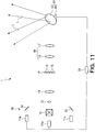
- FIG. 11 is a conceptual diagram illustrating an outline of a structure of an illumination device 1 according to Embodiment 4 of the invention.
- the same reference characters are used to refer to elements that are the same as or similar to those used in Embodiment 3, and such elements will not be described further in detail.
- the laser beam L is not illustrated in the section from the laser light sources 11a, 11b, and 11c to the light scanning device 21.
- one beam expander 12 and one collimating optical system 13 are provided, and the optical guide unit 50 is placed at a stage prior to the beam expander 12.
- the first optical guide member 51 is disposed between the first laser light source 11a and the beam expander 12.
- the second optical guide members 52 are disposed at the positions where the laser beams L from the second laser light source 11b and the third laser light source 11c are guided to the first optical guide member 51.
- the first optical guide member 51 and the second optical guide members 52 synthesize the laser beams L from the laser light sources 11a to 11c at a stage prior to the beam expander 12.
- the synthesized laser beam L is emitted from the first optical guide member 51 to the beam expander 12.
- the optical guide unit 50 emits the laser beams L of mutually different wavelengths emitted from the laser light sources 11a to 11c to the beam expander 12 and the collimating optical system 13, thereby guiding them to the light diffuser 14.
- the collimating optical system 13 is used to collimate the laser beams L of mutually different wavelengths from the laser light sources 11a to 11c.
- the controller 22 controls the timings of emitting the laser beams L from the laser light sources in cooperation with the scan control by the light scanning device 21.
- FIG. 12 is a conceptual diagram illustrating an outline of a structure of an illumination device 1 according to an example not in accordance with the invention.
- the same reference characters are used to refer to elements that are the same as or similar to those used in Embodiment 1, and such elements will not be described further in detail.
- the laser beam L is illustrated only in the section between the laser light source 11 and the collimating optical system 13 and not illustrated in the other sections.
- the relay optical system 18 is removed, and the light diffuser 14 is provided between the light scanning device 21 and the illumination area 40.
- the light scanning device 21 is used to change the propagation direction of the laser beam L travelling from the laser light source 11 through the beam expander 12 and the collimating optical system 13, and the light diffuser 14 is used to diffuse the laser beam L from the light scanning device 21.
- the laser beam L from the laser light source 11 is expanded in beam diameter by the beam expander 12 and the collimating optical system 13 and collimated before irradiating the light scanning device 21.
- the light scanning device 21 scans the laser beam L that has passed through the light diffuser 14 across the illumination area 40, thereby guiding the laser beam L to one of the illumination subareas 41 constituting part of the illumination area 40.
- FIG. 13 is a conceptual diagram illustrating an outline of a structure of an illumination device 1 according to an example not in accordance with the invention.
- the same reference characters are used to refer to elements that are the same as or similar to those used in the previous example, and such elements will not be described further in detail.
- the laser beam L is illustrated only in the section between the laser light source 11 and the collimating optical system 13 and not illustrated in the other sections.
- the laser beam L emitted from the laser light source 11 and changed in direction by the light scanning device 21 includes multiple light components having mutually different wavelengths.
- a spectroscopic unit 60 is provided between the light scanning device 21 and the light diffuser 14. The laser beam L from the light scanning device 21 is incident on the light diffuser 14 via the spectroscopic unit 60. The spectroscopic unit 60 spectrally disperses the laser beam L incident on the spectroscopic unit 60 from the light scanning device 21 or separates the laser beam L into multiple light components having mutually different wavelengths, thereby emitting the light components toward the light diffuser 14.
- the spectroscopic unit 60 of FIG. 13 includes a first spectroscopic guide member 61 and second spectroscopic guide members 62.
- the first spectroscopic guide member 61 has a dichroic mirror for letting a light component having a first wavelength range pass therethrough to guide the light component to the light diffuser 14 while reflecting the light components with the other wavelength ranges.
- the second optical guide members 62 guide to the light diffuser 14 the light components having the other wavelength ranges, reflected by the first spectroscopic guide member 61.
- the light components having different wavelengths guided by the first spectroscopic guide member 61 and the second spectroscopic guide members 62 are guided to different sections of the light diffuser 14 and incident on the associated light diffusers 14 each formed by a hologram. Each of the light components is diffused by the associated light diffuser 14 to illuminate one of the illumination subareas 41 within the illumination area 40.
- the laser beam L incident on the spectroscopic unit 60 is separated into those components having respective wavelength ranges.
- the light component having the red-color wavelength range is guided by the spectroscopic unit 60 such that the light component is incident on the light diffuser 14 optimized for it.
- the light components having the green-color and blue-color wavelength ranges are guided by the spectroscopic unit 60 such that they are incident on the light diffusers 14 optimized for them.
- the controller 22 controls the timings of emitting the laser beams L from the laser light sources in cooperation with the scan control by the light scanning device 21.
- one or more elements selected from among the beam expander 12, and the collimating optical system 13, can be removed, and the invention can also be applied to the illumination device 1 that does not include some of the elements of FIG. 1 .
- the relay optical system 18 is not provided, which is not in accordance with the invention, it is possible to place the irradiation surface 19 of the light scanning device 21 near the light diffuser 14, for example, at a position located away from the light diffuser 14 by the focal distance of the light diffuser 14 or near that position, and illuminate the illumination area 40 with the laser beam L.
- a condenser lens can be provided on the upstream side of the light scanning device 21, or on the side of the laser light source, in addition to the relay optical system 18. Further, a condenser lens can also be provided on the downstream side of the light scanning device 21, or the side opposite the laser light source.
- the application of the illumination device 1 is not particularly limited; for example, the illumination device 1 can be installed on a vehicle, a flying object such as an airplane, a train, a ship, a submarine, or other moving object.
- the illumination device 1 can also be placed at any particular position on those objects.
Landscapes
- Physics & Mathematics (AREA)
- Engineering & Computer Science (AREA)
- Optics & Photonics (AREA)
- General Engineering & Computer Science (AREA)
- General Physics & Mathematics (AREA)
- Condensed Matter Physics & Semiconductors (AREA)
- Electromagnetism (AREA)
- Mechanical Engineering (AREA)
- Microelectronics & Electronic Packaging (AREA)
- Mechanical Optical Scanning Systems (AREA)
- Non-Portable Lighting Devices Or Systems Thereof (AREA)
- Semiconductor Lasers (AREA)
- Arrangement Of Elements, Cooling, Sealing, Or The Like Of Lighting Devices (AREA)
- Lenses (AREA)
- Microscoopes, Condenser (AREA)
Claims (22)
- Beleuchtungsvorrichtung (1), umfassend:eine kohärente Lichtquelle (11), die kohärentes Licht emittiert;einen Lichtdiffusor (14), der das kohärente Licht (L) von der kohärenten Lichtquelle (11) streut;eine Lichtabtastvorrichtung (21), die das kohärente Licht (L) von dem Lichtdiffusor (14) in einem Beleuchtungsbereich (40) abtastet, um das kohärente Licht (L) zu Beleuchtungsunterbereichen (41) zu führen, die Teile des Beleuchtungsbereichs (40) bilden;wobei der Lichtdiffusor (14) eine Mehrzahl von Streuelementen (15) enthält; unddadurch gekennzeichnet, dass ein optisches Relaissystem (18) zwischen dem Lichtdiffusor (14) und der Lichtabtastvorrichtung (21) angeordnet ist, wobei das kohärente Licht (L) von dem Lichtdiffusor (14) durch das optische Relaissystem (18) zu der Lichtabtastvorrichtung (21) geführt wird.
- Beleuchtungsvorrichtung (1) nach Anspruch 1, ferner umfassend eine Steuer- bzw. Regeleinheit (22), die einen Einfallszeitpunkt des kohärenten Lichts (L) auf den bzw. zu dem Lichtdiffusor (14) oder einen Zeitpunkt der Beleuchtung des Beleuchtungsbereichs (40) steuert bzw. regelt.
- Beleuchtungsvorrichtung (1) nach Anspruch 1, ferner umfassend eine Zeitsteuer- bzw. -regeleinheit (22), die einen Zeitpunkt des Emittierens des kohärenten Lichts (L) gemäß dem Abtasten des kohärenten Lichts (L) steuert bzw. regelt, das von der Lichtabtastvorrichtung (21) durchgeführt wird.
- Beleuchtungsvorrichtung (1) nach einem der Ansprüche 1 bis 3,
wobei die Lichtabtastvorrichtung (21) enthält:eine Bestrahlungsfläche bzw. -oberfläche (19), die mit dem kohärenten Licht (L) von dem Lichtdiffusor (14) bestrahlt wird und einen Weg des kohärenten Lichts (L) ändert; undeine Abtastantriebseinheit (20), die eine Anordnung der Bestrahlungsfläche einstellt, undwobei ein Diffusionswinkel des durch den Lichtdiffusor (14) gestreuten kohärenten Lichts (L) kleiner ist als ein Winkel jedes der Beleuchtungsunterbereiche (41) relativ zu der Bestrahlungsfläche. - Beleuchtungsvorrichtung (1) nach Anspruch 4, wobei der Diffusionswinkel des durch den Lichtdiffusor (14) gestreuten kohärenten Lichts (L) größer als 0,05° und kleiner als 2° ist.
- Beleuchtungsvorrichtung (1) nach Anspruch 5, wobei der Winkel jedes der Beleuchtungsunterbereiche (41) relativ zu der Bestrahlungsfläche der Lichtabtastvorrichtung (21) größer als 0,1° und kleiner als 5° ist.
- Beleuchtungsvorrichtung (1) nach einem der Ansprüche 1 bis 6, wobei die Lichtabtastvorrichtung (21) an einer Position angeordnet ist, die auf einer Abbildungsposition des kohärenten Lichts (L) von dem Lichtdiffusor (14) basiert.
- Beleuchtungsvorrichtung (1) nach einem der Ansprüche 1 bis 7, wobei der Lichtdiffusor (14) ein Hologramm ist.
- Beleuchtungsvorrichtung (1) nach einem der Ansprüche 1 bis 7, wobei der Lichtdiffusor (14) ein Mikrolinsen-Array ist.
- Beleuchtungsvorrichtung (1) nach einem der Ansprüche 1 bis 9,
wobei das optische Relaissystem (18) eine erste Relaislinse (16) und eine zweite Relaislinse (17) mit den gleichen Brennweiten enthält; oder
wobei das optische Relaissystem (18) eine erste Relaislinse (16) und eine zweite Relaislinse (17) mit unterschiedlichen Brennweiten enthält. - Beleuchtungsvorrichtung (1) nach einem der Ansprüche 1 bis 10, ferner umfassend einen Strahlaufweiter (12), der zwischen der kohärenten Lichtquelle (11) und dem Lichtdiffusor (14) angeordnet ist und einen Durchmesser des kohärenten Lichts (L) von der kohärenten Lichtquelle (11) aufweitet.
- Beleuchtungsvorrichtung (1) nach Anspruch 11, ferner umfassend ein optisches Kollimationssystem (13), das zwischen dem Strahlaufweiter (12) und dem Lichtdiffusor (14) angeordnet ist und das kohärente Licht (L) von dem Strahlaufweiter (12) kollimiert.
- Beleuchtungsvorrichtung (1) nach Anspruch 8, wobei:eine Mehrzahl der kohärenten Lichtquellen (11), die kohärente Lichter (L) mit zueinander unterschiedlichen Wellenlängen emittieren, bereitgestellt sind,eine Mehrzahl der Lichtdiffusor (14), die entsprechend für die kohärenten Lichtquellen (11) bereitgestellt sind, jeweils bereitgestellt sind und jeder das kohärente Licht (L) von einer entsprechenden der kohärenten Lichtquellen (11) streut, unddie Beleuchtungsvorrichtung (1) ferner eine optische Führungseinheit (50) umfasst, welche die kohärenten Lichter (L), die zueinander unterschiedliche Wellenlängen aufweisen, von der Mehrzahl von Lichtdiffusoren (14) zu der Lichtabtastvorrichtung (21) führt.
- Beleuchtungsvorrichtung (1) nach Anspruch 13,
wobei die optische Führungseinheit (50) enthält:ein erstes optisches Führungsglied (51), das zwischen einem Lichtdiffusor der Mehrzahl von Lichtdiffusoren (14) und der Lichtabtastvorrichtung (21) angeordnet ist; undein zweites optisches Führungsglied (52), welches das kohärente Licht (L) von einem anderen Lichtdiffusor der Mehrzahl von Lichtdiffusoren (14) zu dem ersten optischen Führungsglied (51) führt, undwobei das erste optische Führungsglied (51) das kohärente Licht (L) von dem einen Lichtdiffusor und das kohärente Licht (L) von dem anderen Lichtdiffusor zu der Lichtabtastvorrichtung (21) führt. - Beleuchtungsvorrichtung (1) nach Anspruch 9, wobei:
eine Mehrzahl der kohärenten Lichtquellen (11), die kohärente Lichter (L) mit zueinander unterschiedlichen Wellenlängen emittieren, bereitgestellt sind, und die Beleuchtungsvorrichtung (1) ferner eine optische Führungseinheit (50) umfasst, welche die kohärenten Lichter (L), die zueinander unterschiedliche Wellenlängen aufweisen, von der Mehrzahl kohärenter Lichtquellen (11) zu dem Lichtdiffusor (14) führt. - Beleuchtungsvorrichtung (1) nach Anspruch 15,
wobei die optische Führungseinheit (50) enthält:ein erstes optisches Führungsglied (51), das zwischen einer kohärenten Lichtquelle der Mehrzahl kohärenter Lichtquellen (11) und dem Lichtdiffusor (14) angeordnet ist; undein zweites optisches Führungsglied (52), welches das kohärente Licht (L) von einer anderen kohärenten Lichtquelle der Mehrzahl kohärenter Lichtquellen (11) zu dem ersten optischen Führungsglied (51) führt, undwobei das erste optische Führungsglied (51) das kohärente Licht (L) von der einen kohärenten Lichtquelle und das kohärente Licht von der anderen kohärenten Lichtquelle zu dem Lichtdiffusor (14) führt. - Beleuchtungsvorrichtung (1) nach Anspruch 15 oder 16, ferner umfassend eine Mehrzahl optischer Kollimationssystemen (13a-13c), die entsprechend für die Mehrzahl kohärenter Lichtquellen (11a-11c) bereitgestellt sind, wobei jedes der optischen Kollimationssysteme (11a-11c) das kohärente Licht (L) von einer entsprechenden der kohärenten Lichtquellen (11a-11c) kollimiert, wobei die optische Führungseinheit (50) die kohärenten Lichter (L), die von der Mehrzahl kohärenter Lichtquellen (11a-11c) emittiert wurden und die Mehrzahl optischer Kollimationssystemen (13a-13c) durchlaufen haben, zu dem Lichtdiffusor (14) führt, wobei die kohärenten Lichter (L) zueinander unterschiedliche Wellenlängen aufweisen.
- Beleuchtungsvorrichtung (1) nach Anspruch 15 oder 16, ferner umfassend ein optisches Kollimationssystem (13), das die kohärenten Lichter, die zueinander unterschiedliche Wellenlängen aufweisen, kollimiert,
wobei die optische Führungseinheit (50) die kohärenten Lichter (L), die zueinander unterschiedliche Wellenlängen aufweisen, von der Mehrzahl kohärenter Lichtquellen (11a-11c) zu dem optischen Kollimationssystem (13) emittiert, um die kohärenten Lichter (L) zu dem Lichtdiffusor (14) zu führen. - Beleuchtungsvorrichtung (1) nach Anspruch 18, ferner umfassend einen Strahlaufweiter (12), der die Durchmesser der kohärenten Lichter (L) aufweitet;
wobei die optische Führungseinheit (50) die kohärenten Lichter (L), die zueinander unterschiedlicher Wellenlängen aufweisen, von der Mehrzahl kohärenter Lichtquellen (11a-11c) über den Strahlaufweiter (12) und das optische Kollimationssystem (13) zu dem Lichtdiffusor (14) führt. - Beleuchtungsvorrichtung (1) nach Anspruch 1, wobei die Lichtabtastvorrichtung (21) eine Ausbreitungsrichtung des kohärenten Lichts (L) von der kohärenten Lichtquelle (11) ändert.
- Beleuchtungsvorrichtung (1) nach Anspruch 20, wobei:das kohärente Licht (L), das durch die Lichtabtastvorrichtung (21) in Ausbreitungsrichtung geändert wird, Lichtkomponenten mit zueinander unterschiedlichen Wellenlängen aufweist,eine spektroskopische Einheit (50) ist zwischen der kohärenten Lichtquelle (11a, 11b, 11c) und dem Lichtdiffusor (14) bereitgestellt ist, unddas kohärente Licht (L) von der kohärenten Lichtquelle (11a, 11b, 11c) über die spektroskopische Einheit (50) auf den Lichtdiffusor (14) einfällt.
- Beleuchtungsvorrichtung (1) nach Anspruch 21, wobei die spektroskopische Einheit (50) enthält:ein erstes spektroskopisches Führungsglied (51), das einer Lichtkomponente in einem ersten Wellenlängenbereich erlaubt, es zu passieren und die Lichtkomponente zu dem Lichtdiffusor (14) führt, während Lichtkomponenten in anderen Wellenlängenbereichen reflektiert werden; undein zweites spektroskopisches Führungsglied (52), das die Lichtkomponenten in den anderen Wellenlängenbereichen über Reflektion durch das erste spektroskopische Führungsglied (51) zu dem Lichtdiffusor (14) führt.
Applications Claiming Priority (3)
| Application Number | Priority Date | Filing Date | Title |
|---|---|---|---|
| JP2015175871 | 2015-09-07 | ||
| JP2016092704 | 2016-05-02 | ||
| PCT/JP2016/076303 WO2017043531A1 (ja) | 2015-09-07 | 2016-09-07 | 照明装置 |
Publications (3)
| Publication Number | Publication Date |
|---|---|
| EP3348899A1 EP3348899A1 (de) | 2018-07-18 |
| EP3348899A4 EP3348899A4 (de) | 2019-05-15 |
| EP3348899B1 true EP3348899B1 (de) | 2020-05-27 |
Family
ID=58239856
Family Applications (1)
| Application Number | Title | Priority Date | Filing Date |
|---|---|---|---|
| EP16844392.7A Active EP3348899B1 (de) | 2015-09-07 | 2016-09-07 | Beleuchtungsvorrichtung |
Country Status (5)
| Country | Link |
|---|---|
| US (2) | US10941915B2 (de) |
| EP (1) | EP3348899B1 (de) |
| JP (2) | JP6226107B2 (de) |
| CN (1) | CN107923591B (de) |
| WO (1) | WO2017043531A1 (de) |
Families Citing this family (16)
| Publication number | Priority date | Publication date | Assignee | Title |
|---|---|---|---|---|
| JP6332491B1 (ja) * | 2017-02-13 | 2018-05-30 | オムロン株式会社 | レーザ照明装置およびこれを備えた周辺監視センサ |
| DE102017203889A1 (de) | 2017-03-09 | 2018-09-13 | Bayerische Motoren Werke Aktiengesellschaft | Beleuchtungsvorrichtung für ein Kraftfahrzeug |
| DE102018102575B4 (de) * | 2017-05-25 | 2024-03-07 | Hasco Vision Technology Co., Ltd. | Intelligentes Multifunktions-Kraftfahrzeugscheinwerfermodul |
| JP7046511B2 (ja) * | 2017-07-11 | 2022-04-04 | 株式会社ヴイ・エス・テクノロジ- | 同軸落射照明装置 |
| JP6981068B2 (ja) * | 2017-07-14 | 2021-12-15 | 大日本印刷株式会社 | 照明装置 |
| CN110869666B (zh) * | 2017-07-25 | 2022-07-19 | 大日本印刷株式会社 | 照明装置 |
| JP6756326B2 (ja) | 2017-11-09 | 2020-09-16 | 株式会社デンソー | 状態検出装置 |
| JP2019096381A (ja) | 2017-11-17 | 2019-06-20 | 株式会社小糸製作所 | 車両用灯具 |
| JP2019161127A (ja) * | 2018-03-15 | 2019-09-19 | 豊田合成株式会社 | 発光装置 |
| CN109084189B (zh) * | 2018-06-29 | 2020-06-26 | 北京工业大学 | 远距离激光照明光学系统 |
| CN109681840A (zh) * | 2018-07-30 | 2019-04-26 | 长春理工大学 | 一种新型的激光车灯 |
| US12392732B2 (en) | 2018-10-11 | 2025-08-19 | Asml Netherlands B.V. | Multi-source illumination unit and method of operating the same |
| CN114041079B (zh) * | 2019-06-28 | 2025-07-22 | 大日本印刷株式会社 | 照明装置和照明方法 |
| US11396994B1 (en) * | 2021-02-16 | 2022-07-26 | Ii-Vi Delaware, Inc. | Laser light source having diffuser element and light diverging optic |
| US11460176B2 (en) * | 2021-12-07 | 2022-10-04 | Peijian Xu | Integral control system for galvanometer laser lamp |
| JP2023183842A (ja) * | 2022-06-16 | 2023-12-28 | 東京都公立大学法人 | 推定装置、推定モデル作成装置、推定方法、推定モデル作成方法及びプログラム |
Family Cites Families (37)
| Publication number | Priority date | Publication date | Assignee | Title |
|---|---|---|---|---|
| US6081381A (en) * | 1998-10-26 | 2000-06-27 | Polametrics, Inc. | Apparatus and method for reducing spatial coherence and for improving uniformity of a light beam emitted from a coherent light source |
| EP1710619B1 (de) * | 2004-01-29 | 2018-07-04 | Panasonic Intellectual Property Management Co., Ltd. | Lichtquelleneinrichtung und zweidimensionale bildanzeigeeinheit |
| JP4290095B2 (ja) | 2004-08-16 | 2009-07-01 | キヤノン株式会社 | 表示光学系および画像表示システム |
| GB0718706D0 (en) * | 2007-09-25 | 2007-11-07 | Creative Physics Ltd | Method and apparatus for reducing laser speckle |
| CN101421661B (zh) * | 2006-04-12 | 2010-08-11 | 松下电器产业株式会社 | 图像显示装置 |
| GB0618057D0 (en) * | 2006-09-14 | 2006-10-25 | Perkinelmer Ltd | Improvements in and relating to scanning confocal microscopy |
| JP4359689B2 (ja) * | 2007-02-09 | 2009-11-04 | レーザーテック株式会社 | 検査装置及び検査方法、パターン基板の製造方法 |
| JP4881255B2 (ja) | 2007-08-13 | 2012-02-22 | 株式会社小糸製作所 | 車両用前照灯 |
| JP5125528B2 (ja) * | 2008-01-15 | 2013-01-23 | ソニー株式会社 | 投射型表示装置 |
| DE102008022795B4 (de) | 2008-05-08 | 2020-01-09 | Osram Opto Semiconductors Gmbh | Kfz-Scheinwerfer |
| JP2010205445A (ja) | 2009-02-27 | 2010-09-16 | Seiko Epson Corp | 光源装置、プロジェクター、光量補正方法 |
| JP5464891B2 (ja) * | 2009-04-13 | 2014-04-09 | キヤノン株式会社 | 補償光学系を備えた光画像取得装置、及び、その制御方法 |
| JP2011002547A (ja) * | 2009-06-17 | 2011-01-06 | Konica Minolta Opto Inc | レーザ投射装置 |
| JP5402393B2 (ja) | 2009-08-20 | 2014-01-29 | 大日本印刷株式会社 | 投射型映像表示装置および映像表示方法 |
| SG178386A1 (en) * | 2009-08-31 | 2012-04-27 | 3M Innovative Properties Co | Projection and display system |
| JP2011099816A (ja) * | 2009-11-09 | 2011-05-19 | Sony Corp | 集光レンズ及び3次元距離測定装置 |
| US8585206B2 (en) * | 2010-06-29 | 2013-11-19 | Corning Incorporated | Methods for operating scanning laser projectors to reduce speckle and image flicker |
| KR102227780B1 (ko) * | 2010-09-07 | 2021-03-12 | 다이니폰 인사츠 가부시키가이샤 | 광학 모듈 |
| CN106933014B (zh) * | 2010-09-07 | 2020-05-22 | 大日本印刷株式会社 | 光学模块 |
| JP5603749B2 (ja) * | 2010-11-18 | 2014-10-08 | オリンパス株式会社 | 顕微鏡装置 |
| JP2012146621A (ja) | 2010-12-20 | 2012-08-02 | Stanley Electric Co Ltd | 車両用灯具 |
| JP5403044B2 (ja) * | 2011-04-28 | 2014-01-29 | 大日本印刷株式会社 | 投射装置および投射制御装置 |
| JP5168526B2 (ja) * | 2011-05-10 | 2013-03-21 | 大日本印刷株式会社 | 投射型映像表示装置 |
| JP5541462B2 (ja) * | 2011-05-10 | 2014-07-09 | 大日本印刷株式会社 | 投射型映像表示装置 |
| JP5924578B2 (ja) * | 2012-03-30 | 2016-05-25 | 大日本印刷株式会社 | 照明装置、投射装置および投射型映像表示装置 |
| JP5979481B2 (ja) | 2012-04-16 | 2016-08-24 | 大日本印刷株式会社 | 照明装置、投射装置および投射型映像表示装置 |
| JP5919100B2 (ja) * | 2012-06-04 | 2016-05-18 | 浜松ホトニクス株式会社 | 補償光学システムの調整方法および補償光学システム |
| JP6041093B2 (ja) * | 2012-07-06 | 2016-12-07 | 大日本印刷株式会社 | ホログラム再生装置、ホログラム再生方法、投射型映像表示装置 |
| US8845163B2 (en) * | 2012-08-17 | 2014-09-30 | Ultratech, Inc. | LED-based photolithographic illuminator with high collection efficiency |
| JP6127714B2 (ja) * | 2013-05-23 | 2017-05-17 | セイコーエプソン株式会社 | レーザープロジェクター |
| JP6210754B2 (ja) * | 2013-06-24 | 2017-10-11 | オリンパス株式会社 | 走査型光学顕微鏡 |
| JP6388200B2 (ja) | 2013-12-13 | 2018-09-12 | 大日本印刷株式会社 | 照明装置、投射装置、光学素子及び、光学モジュール |
| CN112984461B (zh) * | 2014-11-07 | 2024-02-02 | 大日本印刷株式会社 | 照明装置 |
| CN107000632B (zh) * | 2014-12-05 | 2020-08-04 | 大日本印刷株式会社 | 照明装置 |
| CN204479610U (zh) * | 2015-04-08 | 2015-07-15 | 哈尔滨理工大学 | 基于扫描探针显微镜的材料耐电晕放电老化性能检测装置 |
| US10627053B2 (en) * | 2015-06-22 | 2020-04-21 | Dai Dippon Printing Co., Ltd. | Illumination device including coherent light source to illuminate an illumination area |
| EP3312498B1 (de) * | 2015-06-22 | 2021-01-06 | Dai Nippon Printing Co., Ltd. | Beleuchtungsvorrichtung |
-
2016
- 2016-09-07 WO PCT/JP2016/076303 patent/WO2017043531A1/ja not_active Ceased
- 2016-09-07 EP EP16844392.7A patent/EP3348899B1/de active Active
- 2016-09-07 CN CN201680050686.2A patent/CN107923591B/zh active Active
- 2016-09-07 US US15/757,675 patent/US10941915B2/en active Active
- 2016-09-07 JP JP2017521608A patent/JP6226107B2/ja active Active
-
2017
- 2017-10-10 JP JP2017197090A patent/JP6823830B2/ja active Active
-
2021
- 2021-01-27 US US17/159,276 patent/US11274801B2/en active Active
Non-Patent Citations (1)
| Title |
|---|
| None * |
Also Published As
| Publication number | Publication date |
|---|---|
| US20210148534A1 (en) | 2021-05-20 |
| JP6226107B2 (ja) | 2017-11-08 |
| US10941915B2 (en) | 2021-03-09 |
| US11274801B2 (en) | 2022-03-15 |
| US20190024862A1 (en) | 2019-01-24 |
| WO2017043531A1 (ja) | 2017-03-16 |
| EP3348899A1 (de) | 2018-07-18 |
| CN107923591B (zh) | 2021-02-19 |
| JP2018049832A (ja) | 2018-03-29 |
| JP6823830B2 (ja) | 2021-02-03 |
| JPWO2017043531A1 (ja) | 2017-09-07 |
| EP3348899A4 (de) | 2019-05-15 |
| CN107923591A (zh) | 2018-04-17 |
Similar Documents
| Publication | Publication Date | Title |
|---|---|---|
| US11274801B2 (en) | Illumination device using coherent light source | |
| US11112080B2 (en) | Illumination device including coherent light source to illuminate an illumination area | |
| Kloppenburg et al. | High-resolution vehicle headlamps: technologies and scanning prototype | |
| EP3312498B1 (de) | Beleuchtungsvorrichtung | |
| US10584854B2 (en) | Illumination device | |
| CN107642756B (zh) | 光学元件和照明设备 | |
| EP3611050B1 (de) | Beleuchtungsvorrichtung | |
| US10760772B2 (en) | Illumination device | |
| CN112073699B (zh) | 投影系统及其投影方法 | |
| CN109790964A (zh) | 用于车辆的照明装置 | |
| CN109643009A (zh) | 具有定制的光照图案的基于激光器的光源 | |
| JP6979168B2 (ja) | 照明装置 | |
| JP2016110823A (ja) | 照明システム |
Legal Events
| Date | Code | Title | Description |
|---|---|---|---|
| STAA | Information on the status of an ep patent application or granted ep patent |
Free format text: STATUS: THE INTERNATIONAL PUBLICATION HAS BEEN MADE |
|
| PUAI | Public reference made under article 153(3) epc to a published international application that has entered the european phase |
Free format text: ORIGINAL CODE: 0009012 |
|
| STAA | Information on the status of an ep patent application or granted ep patent |
Free format text: STATUS: REQUEST FOR EXAMINATION WAS MADE |
|
| 17P | Request for examination filed |
Effective date: 20180308 |
|
| AK | Designated contracting states |
Kind code of ref document: A1 Designated state(s): AL AT BE BG CH CY CZ DE DK EE ES FI FR GB GR HR HU IE IS IT LI LT LU LV MC MK MT NL NO PL PT RO RS SE SI SK SM TR |
|
| AX | Request for extension of the european patent |
Extension state: BA ME |
|
| DAV | Request for validation of the european patent (deleted) | ||
| DAX | Request for extension of the european patent (deleted) | ||
| RIC1 | Information provided on ipc code assigned before grant |
Ipc: F21S 8/12 20060101AFI20170329BHEP Ipc: B60Q 1/14 20060101ALI20170329BHEP Ipc: F21Y 115/10 20160101ALI20170329BHEP Ipc: F21W 101/10 20060101ALI20170329BHEP Ipc: G02B 26/10 20060101ALI20170329BHEP |
|
| A4 | Supplementary search report drawn up and despatched |
Effective date: 20190417 |
|
| RIC1 | Information provided on ipc code assigned before grant |
Ipc: H01S 5/40 20060101ALN20190411BHEP Ipc: F21S 41/30 20180101ALI20190411BHEP Ipc: H01S 5/022 20060101ALN20190411BHEP Ipc: H01S 5/00 20060101AFI20190411BHEP Ipc: G02B 27/14 20060101ALN20190411BHEP Ipc: F21Y 115/10 20160101ALI20190411BHEP Ipc: B60Q 1/04 20060101ALN20190411BHEP Ipc: G02B 26/10 20060101ALI20190411BHEP Ipc: F21S 41/16 20180101ALI20190411BHEP Ipc: B60Q 1/14 20060101ALI20190411BHEP Ipc: H01S 5/062 20060101ALN20190411BHEP Ipc: G02B 27/30 20060101ALN20190411BHEP Ipc: F21S 41/675 20180101ALI20190411BHEP Ipc: F21S 41/00 20180101ALI20190411BHEP Ipc: F21V 23/00 20150101ALI20190411BHEP Ipc: G02B 5/32 20060101ALI20190411BHEP Ipc: F21S 41/20 20180101ALI20190411BHEP |
|
| REG | Reference to a national code |
Ref country code: DE Ref legal event code: R079 Ref document number: 602016037226 Country of ref document: DE Free format text: PREVIOUS MAIN CLASS: F21S0008120000 Ipc: H01S0005000000 |
|
| GRAP | Despatch of communication of intention to grant a patent |
Free format text: ORIGINAL CODE: EPIDOSNIGR1 |
|
| STAA | Information on the status of an ep patent application or granted ep patent |
Free format text: STATUS: GRANT OF PATENT IS INTENDED |
|
| RIC1 | Information provided on ipc code assigned before grant |
Ipc: B60Q 1/04 20060101ALN20191122BHEP Ipc: B60Q 1/14 20060101ALI20191122BHEP Ipc: H01S 5/022 20060101ALN20191122BHEP Ipc: H01S 5/40 20060101ALN20191122BHEP Ipc: G02B 27/30 20060101ALN20191122BHEP Ipc: F21S 41/675 20180101ALI20191122BHEP Ipc: H01S 5/00 20060101AFI20191122BHEP Ipc: H01S 5/062 20060101ALN20191122BHEP Ipc: F21S 41/20 20180101ALI20191122BHEP Ipc: G02B 5/32 20060101ALI20191122BHEP Ipc: F21Y 115/10 20160101ALI20191122BHEP Ipc: G02B 27/14 20060101ALN20191122BHEP Ipc: F21S 41/30 20180101ALI20191122BHEP Ipc: F21V 23/00 20150101ALI20191122BHEP Ipc: G02B 26/10 20060101ALI20191122BHEP Ipc: F21S 41/00 20180101ALI20191122BHEP Ipc: F21S 41/16 20180101ALI20191122BHEP |
|
| RIC1 | Information provided on ipc code assigned before grant |
Ipc: F21S 41/675 20180101ALI20191202BHEP Ipc: H01S 5/40 20060101ALN20191202BHEP Ipc: B60Q 1/04 20060101ALN20191202BHEP Ipc: G02B 27/30 20060101ALN20191202BHEP Ipc: F21S 41/16 20180101ALI20191202BHEP Ipc: F21S 41/00 20180101ALI20191202BHEP Ipc: F21S 41/30 20180101ALI20191202BHEP Ipc: F21V 23/00 20150101ALI20191202BHEP Ipc: G02B 26/10 20060101ALI20191202BHEP Ipc: G02B 5/32 20060101ALI20191202BHEP Ipc: G02B 27/14 20060101ALN20191202BHEP Ipc: B60Q 1/14 20060101ALI20191202BHEP Ipc: H01S 5/00 20060101AFI20191202BHEP Ipc: H01S 5/022 20060101ALN20191202BHEP Ipc: H01S 5/062 20060101ALN20191202BHEP Ipc: F21Y 115/10 20160101ALI20191202BHEP Ipc: F21S 41/20 20180101ALI20191202BHEP |
|
| INTG | Intention to grant announced |
Effective date: 20191220 |
|
| GRAS | Grant fee paid |
Free format text: ORIGINAL CODE: EPIDOSNIGR3 |
|
| GRAA | (expected) grant |
Free format text: ORIGINAL CODE: 0009210 |
|
| STAA | Information on the status of an ep patent application or granted ep patent |
Free format text: STATUS: THE PATENT HAS BEEN GRANTED |
|
| AK | Designated contracting states |
Kind code of ref document: B1 Designated state(s): AL AT BE BG CH CY CZ DE DK EE ES FI FR GB GR HR HU IE IS IT LI LT LU LV MC MK MT NL NO PL PT RO RS SE SI SK SM TR |
|
| REG | Reference to a national code |
Ref country code: GB Ref legal event code: FG4D |
|
| REG | Reference to a national code |
Ref country code: CH Ref legal event code: EP |
|
| REG | Reference to a national code |
Ref country code: AT Ref legal event code: REF Ref document number: 1275542 Country of ref document: AT Kind code of ref document: T Effective date: 20200615 |
|
| REG | Reference to a national code |
Ref country code: DE Ref legal event code: R096 Ref document number: 602016037226 Country of ref document: DE |
|
| REG | Reference to a national code |
Ref country code: LT Ref legal event code: MG4D |
|
| PG25 | Lapsed in a contracting state [announced via postgrant information from national office to epo] |
Ref country code: GR Free format text: LAPSE BECAUSE OF FAILURE TO SUBMIT A TRANSLATION OF THE DESCRIPTION OR TO PAY THE FEE WITHIN THE PRESCRIBED TIME-LIMIT Effective date: 20200828 Ref country code: NO Free format text: LAPSE BECAUSE OF FAILURE TO SUBMIT A TRANSLATION OF THE DESCRIPTION OR TO PAY THE FEE WITHIN THE PRESCRIBED TIME-LIMIT Effective date: 20200827 Ref country code: IS Free format text: LAPSE BECAUSE OF FAILURE TO SUBMIT A TRANSLATION OF THE DESCRIPTION OR TO PAY THE FEE WITHIN THE PRESCRIBED TIME-LIMIT Effective date: 20200927 Ref country code: SE Free format text: LAPSE BECAUSE OF FAILURE TO SUBMIT A TRANSLATION OF THE DESCRIPTION OR TO PAY THE FEE WITHIN THE PRESCRIBED TIME-LIMIT Effective date: 20200527 Ref country code: PT Free format text: LAPSE BECAUSE OF FAILURE TO SUBMIT A TRANSLATION OF THE DESCRIPTION OR TO PAY THE FEE WITHIN THE PRESCRIBED TIME-LIMIT Effective date: 20200928 Ref country code: FI Free format text: LAPSE BECAUSE OF FAILURE TO SUBMIT A TRANSLATION OF THE DESCRIPTION OR TO PAY THE FEE WITHIN THE PRESCRIBED TIME-LIMIT Effective date: 20200527 Ref country code: LT Free format text: LAPSE BECAUSE OF FAILURE TO SUBMIT A TRANSLATION OF THE DESCRIPTION OR TO PAY THE FEE WITHIN THE PRESCRIBED TIME-LIMIT Effective date: 20200527 |
|
| REG | Reference to a national code |
Ref country code: NL Ref legal event code: MP Effective date: 20200527 |
|
| PG25 | Lapsed in a contracting state [announced via postgrant information from national office to epo] |
Ref country code: RS Free format text: LAPSE BECAUSE OF FAILURE TO SUBMIT A TRANSLATION OF THE DESCRIPTION OR TO PAY THE FEE WITHIN THE PRESCRIBED TIME-LIMIT Effective date: 20200527 Ref country code: HR Free format text: LAPSE BECAUSE OF FAILURE TO SUBMIT A TRANSLATION OF THE DESCRIPTION OR TO PAY THE FEE WITHIN THE PRESCRIBED TIME-LIMIT Effective date: 20200527 Ref country code: LV Free format text: LAPSE BECAUSE OF FAILURE TO SUBMIT A TRANSLATION OF THE DESCRIPTION OR TO PAY THE FEE WITHIN THE PRESCRIBED TIME-LIMIT Effective date: 20200527 Ref country code: BG Free format text: LAPSE BECAUSE OF FAILURE TO SUBMIT A TRANSLATION OF THE DESCRIPTION OR TO PAY THE FEE WITHIN THE PRESCRIBED TIME-LIMIT Effective date: 20200827 |
|
| REG | Reference to a national code |
Ref country code: AT Ref legal event code: MK05 Ref document number: 1275542 Country of ref document: AT Kind code of ref document: T Effective date: 20200527 |
|
| PG25 | Lapsed in a contracting state [announced via postgrant information from national office to epo] |
Ref country code: NL Free format text: LAPSE BECAUSE OF FAILURE TO SUBMIT A TRANSLATION OF THE DESCRIPTION OR TO PAY THE FEE WITHIN THE PRESCRIBED TIME-LIMIT Effective date: 20200527 Ref country code: AL Free format text: LAPSE BECAUSE OF FAILURE TO SUBMIT A TRANSLATION OF THE DESCRIPTION OR TO PAY THE FEE WITHIN THE PRESCRIBED TIME-LIMIT Effective date: 20200527 |
|
| PG25 | Lapsed in a contracting state [announced via postgrant information from national office to epo] |
Ref country code: CZ Free format text: LAPSE BECAUSE OF FAILURE TO SUBMIT A TRANSLATION OF THE DESCRIPTION OR TO PAY THE FEE WITHIN THE PRESCRIBED TIME-LIMIT Effective date: 20200527 Ref country code: IT Free format text: LAPSE BECAUSE OF FAILURE TO SUBMIT A TRANSLATION OF THE DESCRIPTION OR TO PAY THE FEE WITHIN THE PRESCRIBED TIME-LIMIT Effective date: 20200527 Ref country code: AT Free format text: LAPSE BECAUSE OF FAILURE TO SUBMIT A TRANSLATION OF THE DESCRIPTION OR TO PAY THE FEE WITHIN THE PRESCRIBED TIME-LIMIT Effective date: 20200527 Ref country code: DK Free format text: LAPSE BECAUSE OF FAILURE TO SUBMIT A TRANSLATION OF THE DESCRIPTION OR TO PAY THE FEE WITHIN THE PRESCRIBED TIME-LIMIT Effective date: 20200527 Ref country code: SM Free format text: LAPSE BECAUSE OF FAILURE TO SUBMIT A TRANSLATION OF THE DESCRIPTION OR TO PAY THE FEE WITHIN THE PRESCRIBED TIME-LIMIT Effective date: 20200527 Ref country code: EE Free format text: LAPSE BECAUSE OF FAILURE TO SUBMIT A TRANSLATION OF THE DESCRIPTION OR TO PAY THE FEE WITHIN THE PRESCRIBED TIME-LIMIT Effective date: 20200527 Ref country code: RO Free format text: LAPSE BECAUSE OF FAILURE TO SUBMIT A TRANSLATION OF THE DESCRIPTION OR TO PAY THE FEE WITHIN THE PRESCRIBED TIME-LIMIT Effective date: 20200527 Ref country code: ES Free format text: LAPSE BECAUSE OF FAILURE TO SUBMIT A TRANSLATION OF THE DESCRIPTION OR TO PAY THE FEE WITHIN THE PRESCRIBED TIME-LIMIT Effective date: 20200527 |
|
| PG25 | Lapsed in a contracting state [announced via postgrant information from national office to epo] |
Ref country code: SK Free format text: LAPSE BECAUSE OF FAILURE TO SUBMIT A TRANSLATION OF THE DESCRIPTION OR TO PAY THE FEE WITHIN THE PRESCRIBED TIME-LIMIT Effective date: 20200527 Ref country code: PL Free format text: LAPSE BECAUSE OF FAILURE TO SUBMIT A TRANSLATION OF THE DESCRIPTION OR TO PAY THE FEE WITHIN THE PRESCRIBED TIME-LIMIT Effective date: 20200527 |
|
| REG | Reference to a national code |
Ref country code: DE Ref legal event code: R097 Ref document number: 602016037226 Country of ref document: DE |
|
| PLBE | No opposition filed within time limit |
Free format text: ORIGINAL CODE: 0009261 |
|
| STAA | Information on the status of an ep patent application or granted ep patent |
Free format text: STATUS: NO OPPOSITION FILED WITHIN TIME LIMIT |
|
| REG | Reference to a national code |
Ref country code: CH Ref legal event code: PL |
|
| 26N | No opposition filed |
Effective date: 20210302 |
|
| PG25 | Lapsed in a contracting state [announced via postgrant information from national office to epo] |
Ref country code: SI Free format text: LAPSE BECAUSE OF FAILURE TO SUBMIT A TRANSLATION OF THE DESCRIPTION OR TO PAY THE FEE WITHIN THE PRESCRIBED TIME-LIMIT Effective date: 20200527 |
|
| REG | Reference to a national code |
Ref country code: BE Ref legal event code: MM Effective date: 20200930 |
|
| PG25 | Lapsed in a contracting state [announced via postgrant information from national office to epo] |
Ref country code: LU Free format text: LAPSE BECAUSE OF NON-PAYMENT OF DUE FEES Effective date: 20200907 |
|
| PG25 | Lapsed in a contracting state [announced via postgrant information from national office to epo] |
Ref country code: LI Free format text: LAPSE BECAUSE OF NON-PAYMENT OF DUE FEES Effective date: 20200930 Ref country code: IE Free format text: LAPSE BECAUSE OF NON-PAYMENT OF DUE FEES Effective date: 20200907 Ref country code: BE Free format text: LAPSE BECAUSE OF NON-PAYMENT OF DUE FEES Effective date: 20200930 Ref country code: CH Free format text: LAPSE BECAUSE OF NON-PAYMENT OF DUE FEES Effective date: 20200930 |
|
| PG25 | Lapsed in a contracting state [announced via postgrant information from national office to epo] |
Ref country code: TR Free format text: LAPSE BECAUSE OF FAILURE TO SUBMIT A TRANSLATION OF THE DESCRIPTION OR TO PAY THE FEE WITHIN THE PRESCRIBED TIME-LIMIT Effective date: 20200527 Ref country code: MT Free format text: LAPSE BECAUSE OF FAILURE TO SUBMIT A TRANSLATION OF THE DESCRIPTION OR TO PAY THE FEE WITHIN THE PRESCRIBED TIME-LIMIT Effective date: 20200527 Ref country code: CY Free format text: LAPSE BECAUSE OF FAILURE TO SUBMIT A TRANSLATION OF THE DESCRIPTION OR TO PAY THE FEE WITHIN THE PRESCRIBED TIME-LIMIT Effective date: 20200527 |
|
| PG25 | Lapsed in a contracting state [announced via postgrant information from national office to epo] |
Ref country code: MK Free format text: LAPSE BECAUSE OF FAILURE TO SUBMIT A TRANSLATION OF THE DESCRIPTION OR TO PAY THE FEE WITHIN THE PRESCRIBED TIME-LIMIT Effective date: 20200527 Ref country code: MC Free format text: LAPSE BECAUSE OF FAILURE TO SUBMIT A TRANSLATION OF THE DESCRIPTION OR TO PAY THE FEE WITHIN THE PRESCRIBED TIME-LIMIT Effective date: 20200527 |
|
| P01 | Opt-out of the competence of the unified patent court (upc) registered |
Effective date: 20230524 |
|
| PGFP | Annual fee paid to national office [announced via postgrant information from national office to epo] |
Ref country code: GB Payment date: 20230920 Year of fee payment: 8 |
|
| GBPC | Gb: european patent ceased through non-payment of renewal fee |
Effective date: 20240907 |
|
| PG25 | Lapsed in a contracting state [announced via postgrant information from national office to epo] |
Ref country code: GB Free format text: LAPSE BECAUSE OF NON-PAYMENT OF DUE FEES Effective date: 20240907 |
|
| PGFP | Annual fee paid to national office [announced via postgrant information from national office to epo] |
Ref country code: DE Payment date: 20250919 Year of fee payment: 10 |
|
| PGFP | Annual fee paid to national office [announced via postgrant information from national office to epo] |
Ref country code: FR Payment date: 20250922 Year of fee payment: 10 |