EP3348859B1 - Chain - Google Patents
Chain Download PDFInfo
- Publication number
- EP3348859B1 EP3348859B1 EP18150533.0A EP18150533A EP3348859B1 EP 3348859 B1 EP3348859 B1 EP 3348859B1 EP 18150533 A EP18150533 A EP 18150533A EP 3348859 B1 EP3348859 B1 EP 3348859B1
- Authority
- EP
- European Patent Office
- Prior art keywords
- chain plate
- chain
- edges
- accompanying
- recess
- Prior art date
- Legal status (The legal status is an assumption and is not a legal conclusion. Google has not performed a legal analysis and makes no representation as to the accuracy of the status listed.)
- Active
Links
- 230000005540 biological transmission Effects 0.000 description 10
- 238000000034 method Methods 0.000 description 3
- 230000002093 peripheral effect Effects 0.000 description 3
- 230000004048 modification Effects 0.000 description 1
- 238000012986 modification Methods 0.000 description 1
- 238000000926 separation method Methods 0.000 description 1
Images


Classifications
-
- B—PERFORMING OPERATIONS; TRANSPORTING
- B62—LAND VEHICLES FOR TRAVELLING OTHERWISE THAN ON RAILS
- B62M—RIDER PROPULSION OF WHEELED VEHICLES OR SLEDGES; POWERED PROPULSION OF SLEDGES OR SINGLE-TRACK CYCLES; TRANSMISSIONS SPECIALLY ADAPTED FOR SUCH VEHICLES
- B62M9/00—Transmissions characterised by use of an endless chain, belt, or the like
- B62M9/04—Transmissions characterised by use of an endless chain, belt, or the like of changeable ratio
- B62M9/06—Transmissions characterised by use of an endless chain, belt, or the like of changeable ratio using a single chain, belt, or the like
- B62M9/08—Transmissions characterised by use of an endless chain, belt, or the like of changeable ratio using a single chain, belt, or the like involving eccentrically- mounted or elliptically-shaped driving or driven wheel; with expansible driving or driven wheel
-
- F—MECHANICAL ENGINEERING; LIGHTING; HEATING; WEAPONS; BLASTING
- F16—ENGINEERING ELEMENTS AND UNITS; GENERAL MEASURES FOR PRODUCING AND MAINTAINING EFFECTIVE FUNCTIONING OF MACHINES OR INSTALLATIONS; THERMAL INSULATION IN GENERAL
- F16G—BELTS, CABLES, OR ROPES, PREDOMINANTLY USED FOR DRIVING PURPOSES; CHAINS; FITTINGS PREDOMINANTLY USED THEREFOR
- F16G13/00—Chains
- F16G13/02—Driving-chains
- F16G13/06—Driving-chains with links connected by parallel driving-pins with or without rollers so called open links
-
- F—MECHANICAL ENGINEERING; LIGHTING; HEATING; WEAPONS; BLASTING
- F16—ENGINEERING ELEMENTS AND UNITS; GENERAL MEASURES FOR PRODUCING AND MAINTAINING EFFECTIVE FUNCTIONING OF MACHINES OR INSTALLATIONS; THERMAL INSULATION IN GENERAL
- F16H—GEARING
- F16H9/00—Gearings for conveying rotary motion with variable gear ratio, or for reversing rotary motion, by endless flexible members
- F16H9/02—Gearings for conveying rotary motion with variable gear ratio, or for reversing rotary motion, by endless flexible members without members having orbital motion
- F16H9/24—Gearings for conveying rotary motion with variable gear ratio, or for reversing rotary motion, by endless flexible members without members having orbital motion using chains or toothed belts, belts in the form of links; Chains or belts specially adapted to such gearing
-
- F—MECHANICAL ENGINEERING; LIGHTING; HEATING; WEAPONS; BLASTING
- F16—ENGINEERING ELEMENTS AND UNITS; GENERAL MEASURES FOR PRODUCING AND MAINTAINING EFFECTIVE FUNCTIONING OF MACHINES OR INSTALLATIONS; THERMAL INSULATION IN GENERAL
- F16H—GEARING
- F16H7/00—Gearings for conveying rotary motion by endless flexible members
- F16H7/06—Gearings for conveying rotary motion by endless flexible members with chains
Definitions
- the disclosure relates to a chain, and more particularly to a chain for use in a variable speed drivetrain.
- a transmission chain is an assembly of inner chain plates, outer chain plates, connecting rods and rollers, and is cooperatively used with sprockets.
- the transmission chain When the transmission chain is used in a variable speed drivetrain, it would be frequently moved from one sprocket to another. Therefore, auxiliary structures of the chain plates are needed for aiding the movement of the transmission chain among the sprockets.
- Taiwanese Patent No. 1500555 discloses a conventional inner chain plate that has two opposite end sections, a connecting section connected between the end sections, and a recess formed in a side surface of the connecting section.
- the recess has two arc-shaped edges that are respectively proximate to the end sections .
- Taiwanese Utility Model Patent No. M338930 discloses a conventional transmission chain for a variable speed bicycle.
- the conventional transmission chain includes a plurality of inner link units each including two spaced-apart inner chain plates, and a plurality of outer link units each including two spaced-apart outer chain plates.
- the inner and outer link units are interconnected in an alternating arrangement.
- each of the inner chain plates of the inner link units is formed with an inclined groove
- each of the outer chain plates of the outer link units is formed with an inclined groove as well.
- the inclined grooves of the inner chain plates of each of the inner link units are oblique to each other.
- the inclined grooves of the outer chain plates of each of the outer link units are oblique to each other.
- the inclined grooves serve to increase the width of the space defined between the inner chain plates of each of the inner link units, the width is insufficient since the inclined grooves of the inner chain plates of each of the inner link units are oblique to each other.
- Taiwanese Utility Model Patent No. M287192 discloses a conventional outer chain plate that has a protrusion.
- a pair of the conventional outer chain plates cooperatively serve as an outer link unit of a transmission chain in such a manner that the protrusions thereof protrude away from each other, the protrusions thereof serve to diminish collision between the transmission chain and a set of sprockets.
- the width of a space defined in an inner link unit of the transmission chain is still relatively small.
- EP0844414A1 discloses a derailleur bicycle chain (15) that includes a plurality of intermediate links (14), a plurality of pairs of outer links (18A, 18B), and a plurality of fasteners (22).
- Each fastener (22) connects an end of one of the plurality of intermediate links (14) between a corresponding pair of outer links (18A, 18B) so that the plurality of intermediate links (14) alternate with the plurality of pairs of outer links (18A, 18B) .
- Each intermediate link defines a recess (26) between each end thereof for receiving a sprocket tooth (30) therein, and each end of each intermediate link (14) forms drive faces (34, 36) facing toward and away from the recess (26).
- US2016/153526A1 discloses a chain plate structure that includes a link plate body and a sleeve.
- the link plate body has an acting surface being provided with a first approach edge, two combining portions, and a limiting block located adjacent to the first approach edge.
- the limiting block has an altitude higher than an altitude of the acting surface.
- the sleeve is mounted on the link plate body and has a through hole whose maximum diameter is greater than a maximum diameter of a raised ring peripherally formed on the corresponding one of the combining portions. Therefore, when two of the link plate bodies are combined together, a first space is formed between the acting surfaces of the two aligned link plate bodies.
- the limiting block serves to limit the first space, while the sleeve is allowed to move on one of the combining portions so as to provide a second space.
- EP2535616A2 discloses an inner link plate (14) for a chain (10).
- the inner link plate has a longitudinal centerline, an inside surface (26) arranged to face another inner link plate when the chain is assembled, an outside surface (27) opposite to the inside surface, and an outer peripheral edge (28) disposed between the inside and outside surfaces .
- the bicycle inner link plate basically has a first end portion (29), a second end portion (30) and a connecting portion (31).
- the first and second end portions are each provided with a connecting opening (29a,30a).
- the connecting portion includes a recess (32) disposed on the inside surface of the connecting portion.
- the recess has a maximum longitudinal width on the outer peripheral edge, and a minimum longitudinal width in a region adjacent the longitudinal centerline.
- the recess at least extends from the outer peripheral edge to the longitudinal centerline.
- an object of the disclosure is to provide a chain that can alleviate at least one of the drawbacks of the prior arts.
- the chain includes at least one inner link unit and at least one outer link unit.
- the inner link unit includes an inner chain plate, an accompanying chain plate that is spaced apart from the inner chain plate, and an engaging space that is defined between the inner chain plate and the accompanying chain plate.
- the inner chain plate has two end sections that are spaced apart from each other along a central line, and a connecting section that interconnects the end sections and that has a first recess recessed away from the accompanying chain plate.
- Each of the end sections has a rod hole.
- the first recess has two first edges that are parallel to each other.
- the accompanying chain plate of the at least one inner link unit has a second recess that is recessed away from the inner chain plate.
- the second recess has two second edges that are parallel to each other and that are spaced apart from each other.
- the at least one outer link unit including two spaced-apart outer chain plates that are respectively disposed at two opposite lateral sides of said at least one inner link unit.
- the first edges of the first recess and the second edges of the second recess extend in the same direction.
- Each of the first edges of the first recess and the second edges of the second recess comprise straight edges.
- the first edges of the inner chain plate of the at least one inner link unit extend across the central line.
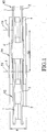
- the first embodiment of the chain according to the disclosure is cooperatively used with a sprocket assembly 9 (see Figure 2 ).
- the sprocket assembly 9 includes twelve coaxially-arranged sprockets 90, each of which has a plurality of teeth 91.
- the chain includes a plurality of inner link units 92 that are spaced apart from each other.
- Each of the inner link units 92 includes an inner chain plate 1, an accompanying chain plate 2 that is spaced apart from the inner chain plate 1, and an engaging space 3 that is defined between the inner chain plate 1 and the accompanying chain plate 2.
- the chain further includes a plurality of outer link units 94 each of which is connected between two adjacent ones of the inner link units 92, and a plurality of connecting rods 5 each of which has a central axis 51, and interconnects one of the inner link units 92 and a corresponding one of the outer link units 94.
- Each of the outer link units 94 includes two spaced-apart outer chain plates 4 that are respectively disposed at opposite lateral sides of the corresponding inner link unit 92.
- the central axes 51 of two adjacent ones of the connecting rods 5 are spaced apart from each other by a link distance 52.
- the ratio of the link distance 52 to the width 6 of the outer link units 94 is 2.39 ⁇ 0.12.
- the link distance 52 corresponds to the chordal pitch of each of the sprockets 90.
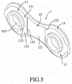
- the inner chain plate 1 of each of the inner link units 92 has two end sections 11 that are spaced apart from each other along a central line 10 (see Figure 4 ), a connecting section 12 that interconnects the end sections 11, and a guide section 13 that surrounds the end sections 11 and the connecting section 12.
- Each of the end sections 11 of the inner chain plate 1 has a base wall 111 that is integrally connected to the connecting section 12, a protrusion 112 that protrudes from the base wall 111 toward the accompanying chain plate 2, and a rod hole 113 that is formed through the base wall 111 and the protrusion 112.
- the base wall has an outer annular surface 114 that faces away from the accompanying chain plate 2, and an inner annular surface 115 that faces toward the accompanying chain plate 2.
- the connecting section 12 has a first recess 121 that is recessed away from the accompanying chain plate 2, and an outer connecting surface 122 that faces away from the accompanying chain plate 2.
- the first recess 121 has two first edges 123 that are spaced apart from each other and that are respectively proximate to the end sections 11. In this embodiment, the first edges 123 extend across the central line 10, are perpendicular to the central line 10, and are parallel to each other.
- the outer connecting surface 122 of the connecting section 12 is connected to the outer annular surfaces 114 of the end sections 11, and is flush with the outer annular surfaces 114.
- the central line 10 substantially passes through the center of the rod hole 113 of each of the end sections 11.
- the guide section 13 has two inclined guide surfaces 131 that are respectively located at two opposite sides of the central line 10 and that face toward the accompanying chain plate 2.
- Each of the inclined guide surfaces 131 extends along a periphery of the inner chain plate 1 and extends over the connecting section 12.
- Each of the inclined guide surfaces 131 is inclined away from the accompanying chain plate 2 in a direction away from the central line 10.
- the accompanying chain plate 2 of the inner link unit 92 may be structurally identical to the inner chain plate 1.
- the accompanying chain plate 2 has a second recess 21 that is recessed away from the inner chain plate 1.
- the inner link unit 92 has first and second recesses 121, 21 that face toward each other.
- the second recess 21 has two second edges 211 that respectively correspond in position to the first edges 123 of the first recess 121 of the inner chain plate 1 and that are parallel to the first edges 123 (i.e., the first recess 121 and the second recess 21 are parallel to each other).
- a distance between the second edges 211 is the same as that between the first edges 123.
- the engaging space 3 defined between the inner chain plate 1 and the accompanying chain plate 2 has a relatively large width. It should be noted that since the first recess 121 and the second recess 21 are parallel to each other, the width (or an opening) of the engaging space 3 is sufficiently increased so as to facilitate entrance of a corresponding one of the teeth 91 of the sprockets 90 into the engaging space 3 during the movement of the chain from one of the sprockets 90 to another.
- the inclined guide surfaces 131 of the guide section 13 serve to guide the entrance of a corresponding one of the teeth 91 of the sprockets 90 into the engaging space 3, so the chain is smoothly movable among the sprockets 90. It should be noted that since the first edges 123 of the first recess 121 of the inner chain plate 1 are parallel to each other, in a forming process, the inner chain plate 1 can be easily separated from a forming die.
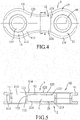
- the second embodiment of the chain according to the disclosure is different from the first embodiment in the inner link units 92.
- the outer connecting surface 122 of the connecting section 12 of the inner chain plate 1 is not flush with the outer annular surfaces 114 of the end sections 11, and is farther from the accompanying chain plate 2 than the outer annular surfaces 114.
- the connecting section 12 of the inner chain plate 1 is misaligned from the end sections 11, and is farther from the accompanying chain plate 2 than the end sections 11, so that the connecting section 12 cooperates with the end sections 11 to form the first recess 121.
- the outer connecting surface 122 of the connecting section 12 is flush with an outer surface 41 of a corresponding one of the outer chain plates 4.
- the accompanying chain plate 2 is structurally identical to the inner chain plate 1.
- the ratio of the link distance 52 to a maximum width 7 of the inner link unit 92 is 2.39 ⁇ 0.12.
- the ratio of the link distance 52 to a maximum width 8 of the engaging space 3 defined between the inner chain plate 1 and the accompanying chain plate 2 is 5.5 ⁇ 0.12.
- the engaging space 3 has a relatively large width, and the chain is smoothly movable among the sprockets 90 (see Figure 2 ) .
- the maximum width 8 of the engaging space 3 is equal to the width of a space defined between the outer chain plates 4 of the outer link unit 94.
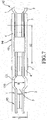
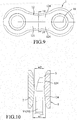
- the third embodiment of the chain according to the disclosure is similar to the first embodiment.
- the connecting section 12 of the inner chain plate 1 further has two inclined inner surfaces 124 that are respectively located at the opposite sides of the central line 10 and that cooperatively define the first recess 121.
- Each of the inclined inner surfaces 124 is inclined away from the accompanying chain plate 2 in the direction away from the central line 10.
- the accompanying chain plate 2 is structurally identical to the inner chain plate 1.
- the width (w1, see Figure 10 ) of the opening of the engaging space 3 is relatively large so as to facilitate entrance of a corresponding one of the teeth 91 of the sprockets 90 into the engaging space 3 during the movement of the chain from one of the sprockets 90 to another.
- the width (w2, see Figure 10 ) of a middle portion of the engaging space 3 is relatively small, so the engagement between the engaging space 3 and the corresponding one of the teeth 91 is steady.
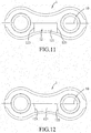
- the fourth embodiment of the chain according to the disclosure is different from the first embodiment in the first recess 121 of the inner chain plate 1.
- the first recess 121 of the fourth embodiment is formed at only one side of the central line 10, and the first edges 123 of the first recess 121 are perpendicular to the central line 10.
- the accompanying chain plate (not shown in Figure 11 ) is structurally identical to the inner chain plate 1.
- the fifth embodiment of the chain according to the disclosure is similar to the fourth embodiment.
- the first recess 121 of the fifth embodiment is also formed at only one side of the central line 10, but the first edges 123 of the first recess 121 are oblique to the central line 10.
- the accompanying chain plate (not shown in Figure 12 ) is structurally identical to the inner chain plate 1, and the first edges 123 of the first recess 121 and the second edges of the second recess (not shown in Figure 12 ) extend in the same direction.
- the first recess 121 of each of the fourth and fifth embodiments also serves to increase the width of the opening of the engaging space 3 (with reference to Figures 1 and 5 ).
- first recess 121 of the inner chain plate 1 and the second recess 21 of the accompanying chain plate 2 serve to increase the width of the opening of the engaging space 3, so the chain of this disclosure is suitable for a sprocket assembly that consists of a relatively large number of sprockets.
- first edges 123 of the first recess 121 of the inner chain plate 1 are parallel to each other, the inner chain plate 1 can be easily separated from a forming die in the forming process thereof.
Applications Claiming Priority (1)
| Application Number | Priority Date | Filing Date | Title |
|---|---|---|---|
| TW106101166A TWI617749B (zh) | 2017-01-13 | 2017-01-13 | Chain and its inner chain |
Publications (2)
| Publication Number | Publication Date |
|---|---|
| EP3348859A1 EP3348859A1 (en) | 2018-07-18 |
| EP3348859B1 true EP3348859B1 (en) | 2020-09-23 |
Family
ID=60937636
Family Applications (1)
| Application Number | Title | Priority Date | Filing Date |
|---|---|---|---|
| EP18150533.0A Active EP3348859B1 (en) | 2017-01-13 | 2018-01-08 | Chain |
Country Status (5)
| Country | Link |
|---|---|
| US (1) | US20180201341A1 (ja) |
| EP (1) | EP3348859B1 (ja) |
| JP (1) | JP6573685B2 (ja) |
| PT (1) | PT3348859T (ja) |
| TW (1) | TWI617749B (ja) |
Families Citing this family (4)
| Publication number | Priority date | Publication date | Assignee | Title |
|---|---|---|---|---|
| TWI675157B (zh) * | 2018-10-15 | 2019-10-21 | 大亞鏈條股份有限公司 | 鏈條 |
| TW202035892A (zh) * | 2019-03-27 | 2020-10-01 | 葡萄牙商米蘭達&艾爾茅公司 | 驅動鏈系統 |
| TWI722753B (zh) * | 2020-01-06 | 2021-03-21 | 桂盟企業股份有限公司 | 內鏈片 |
| TWI741728B (zh) * | 2020-08-10 | 2021-10-01 | 桂盟企業股份有限公司 | 鏈條及車輪傳動裝置 |
Family Cites Families (27)
| Publication number | Priority date | Publication date | Assignee | Title |
|---|---|---|---|---|
| FR2396897A1 (fr) * | 1977-07-06 | 1979-02-02 | Sedis Transmissions Mec | Chaine de transmission |
| EP0316238A1 (fr) * | 1987-11-12 | 1989-05-17 | Sachs-Huret S.A. | Chaîne de transmission |
| JP2872676B2 (ja) * | 1988-08-03 | 1999-03-17 | 株式会社シマノ | 自転車用チェン |
| DE4031865A1 (de) * | 1990-09-18 | 1992-03-26 | Heinz Jacht | Stufenlos verstellbares fahrradgetriebe |
| US5073153A (en) * | 1991-01-03 | 1991-12-17 | Wu Chia L | Chain |
| US5098349A (en) * | 1991-06-27 | 1992-03-24 | Wu Chia L | Chain |
| CN2126348U (zh) * | 1992-04-22 | 1992-12-30 | 吴盈进 | 易于变速的链条 |
| US5203745A (en) * | 1992-05-08 | 1993-04-20 | Wang Wen B | Inner and outer chain plates for bicycle having multiple wheels |
| JPH09217797A (ja) * | 1996-02-13 | 1997-08-19 | Tsubakimoto Chain Co | 低騒音・耐摩耗チェーン |
| IT1285011B1 (it) * | 1996-03-18 | 1998-06-03 | Campagnolo Srl | Catena di trasmissione, particolarmente per bicicletta. |
| US5921881A (en) * | 1996-11-21 | 1999-07-13 | Shimano, Inc. | Narrow bicycle chain with inner links that receive sprocket teeth within a bottom recess |
| JP2003240062A (ja) * | 2002-02-15 | 2003-08-27 | Enuma Chain Seisakusho:Kk | オートバイ用のチェーン |
| EP1617101A1 (en) * | 2004-07-16 | 2006-01-18 | Kmc Chain Industrial Co., Ltd. | Lightweight drive chain |
| TWM287192U (en) | 2005-10-21 | 2006-02-11 | Yaban Chain Ind Co Ltd | Varied chain structure for downhill race |
| US7325391B1 (en) * | 2007-03-02 | 2008-02-05 | Shimano Inc. | Bicycle chain |
| ITMI20071660A1 (it) * | 2007-08-09 | 2009-02-10 | Campagnolo Srl | Sistema di trasmissione del moto di una bicicletta |
| TWM338930U (en) | 2008-03-25 | 2008-08-21 | Ta Ya Chain Co Ltd | Transmission chain for a bicycle |
| US8734280B2 (en) * | 2011-06-15 | 2014-05-27 | Shimano Inc. | Inner link plate for bicycle chain |
| CN103307208A (zh) * | 2012-03-07 | 2013-09-18 | 雅邦企业股份有限公司 | 快速变速链条及其外链片的结构 |
| US9303725B2 (en) * | 2013-09-27 | 2016-04-05 | Shimano Inc. | Bicycle chain |
| US9255624B2 (en) * | 2013-09-27 | 2016-02-09 | Shimano Inc. | Bicycle chain |
| US9303726B2 (en) * | 2013-09-27 | 2016-04-05 | Shimano Inc. | Bicycle chain |
| US10190659B2 (en) * | 2014-04-10 | 2019-01-29 | Shimano Inc. | Bicycle chain |
| US10295019B2 (en) * | 2014-04-28 | 2019-05-21 | Shimano Inc. | Bicycle chain |
| US20160040753A1 (en) * | 2014-08-07 | 2016-02-11 | Wen-Pin Wang | Link plate |
| US9541159B2 (en) * | 2014-12-01 | 2017-01-10 | Wen-Pin Wang | Chain plate structure |
| TWM542092U (zh) * | 2017-01-13 | 2017-05-21 | Kmc Chain Industrial Co Ltd | 鏈條及其內鏈片 |
-
2017
- 2017-01-13 TW TW106101166A patent/TWI617749B/zh active
-
2018
- 2018-01-04 US US15/861,790 patent/US20180201341A1/en not_active Abandoned
- 2018-01-05 JP JP2018000445A patent/JP6573685B2/ja active Active
- 2018-01-08 PT PT181505330T patent/PT3348859T/pt unknown
- 2018-01-08 EP EP18150533.0A patent/EP3348859B1/en active Active
Non-Patent Citations (1)
| Title |
|---|
| None * |
Also Published As
| Publication number | Publication date |
|---|---|
| TWI617749B (zh) | 2018-03-11 |
| TW201825802A (zh) | 2018-07-16 |
| PT3348859T (pt) | 2020-11-23 |
| JP2018112314A (ja) | 2018-07-19 |
| EP3348859A1 (en) | 2018-07-18 |
| JP6573685B2 (ja) | 2019-09-11 |
| US20180201341A1 (en) | 2018-07-19 |
Similar Documents
| Publication | Publication Date | Title |
|---|---|---|
| EP3348859B1 (en) | Chain | |
| TWI618873B (zh) | 自行車鏈條 | |
| US11110991B2 (en) | Chainring | |
| CN1144727C (zh) | 带有链条支撑凸台的自行车链轮 | |
| TWI628378B (zh) | Link | |
| DE102015017202B4 (de) | Fahrradkette | |
| US20060166770A1 (en) | Gear assembly for a bicycle gear change | |
| JPH0351933B2 (ja) | ||
| TWI750262B (zh) | 多重小齒輪配置及具有此種多重小齒輪配置之自行車驅動器 | |
| US20200063850A1 (en) | Chainring | |
| US20180252294A1 (en) | Bicycle chain | |
| US20170016524A1 (en) | Bicycle sprocket wheel | |
| TW201930139A (zh) | 單鏈輪 | |
| US20080277247A1 (en) | Spline roller for a belt-driven roller conveyor, and method for making | |
| JP2832412B2 (ja) | チェーンベルト | |
| TWI675157B (zh) | 鏈條 | |
| EP3406932A1 (en) | Drive chain and method for manufacturing a drive chain | |
| TWM542092U (zh) | 鏈條及其內鏈片 | |
| JP2005299755A (ja) | 動力伝達チェーンおよびこれを備える動力伝達装置 | |
| CN214146482U (zh) | 一种高强度汽车曲轴链轮结构 | |
| CN216842980U (zh) | 一种齿形角度可变的链轮 | |
| CN104209448A (zh) | 动力传递链的组装方法以及组装装置 | |
| US20210356017A1 (en) | Drive chain and method for manufacturing a drive-chain | |
| JPS5825159Y2 (ja) | ダブル歯付ベルト | |
| EP3636957B1 (en) | Bicycle chain |
Legal Events
| Date | Code | Title | Description |
|---|---|---|---|
| PUAI | Public reference made under article 153(3) epc to a published international application that has entered the european phase |
Free format text: ORIGINAL CODE: 0009012 |
|
| STAA | Information on the status of an ep patent application or granted ep patent |
Free format text: STATUS: THE APPLICATION HAS BEEN PUBLISHED |
|
| AK | Designated contracting states |
Kind code of ref document: A1 Designated state(s): AL AT BE BG CH CY CZ DE DK EE ES FI FR GB GR HR HU IE IS IT LI LT LU LV MC MK MT NL NO PL PT RO RS SE SI SK SM TR |
|
| AX | Request for extension of the european patent |
Extension state: BA ME |
|
| STAA | Information on the status of an ep patent application or granted ep patent |
Free format text: STATUS: REQUEST FOR EXAMINATION WAS MADE |
|
| 17P | Request for examination filed |
Effective date: 20190118 |
|
| RBV | Designated contracting states (corrected) |
Designated state(s): AL AT BE BG CH CY CZ DE DK EE ES FI FR GB GR HR HU IE IS IT LI LT LU LV MC MK MT NL NO PL PT RO RS SE SI SK SM TR |
|
| STAA | Information on the status of an ep patent application or granted ep patent |
Free format text: STATUS: EXAMINATION IS IN PROGRESS |
|
| 17Q | First examination report despatched |
Effective date: 20190925 |
|
| GRAP | Despatch of communication of intention to grant a patent |
Free format text: ORIGINAL CODE: EPIDOSNIGR1 |
|
| STAA | Information on the status of an ep patent application or granted ep patent |
Free format text: STATUS: GRANT OF PATENT IS INTENDED |
|
| INTG | Intention to grant announced |
Effective date: 20200416 |
|
| GRAS | Grant fee paid |
Free format text: ORIGINAL CODE: EPIDOSNIGR3 |
|
| GRAA | (expected) grant |
Free format text: ORIGINAL CODE: 0009210 |
|
| STAA | Information on the status of an ep patent application or granted ep patent |
Free format text: STATUS: THE PATENT HAS BEEN GRANTED |
|
| AK | Designated contracting states |
Kind code of ref document: B1 Designated state(s): AL AT BE BG CH CY CZ DE DK EE ES FI FR GB GR HR HU IE IS IT LI LT LU LV MC MK MT NL NO PL PT RO RS SE SI SK SM TR |
|
| REG | Reference to a national code |
Ref country code: GB Ref legal event code: FG4D |
|
| REG | Reference to a national code |
Ref country code: CH Ref legal event code: EP |
|
| REG | Reference to a national code |
Ref country code: IE Ref legal event code: FG4D |
|
| REG | Reference to a national code |
Ref country code: AT Ref legal event code: REF Ref document number: 1316682 Country of ref document: AT Kind code of ref document: T Effective date: 20201015 Ref country code: DE Ref legal event code: R096 Ref document number: 602018007943 Country of ref document: DE |
|
| REG | Reference to a national code |
Ref country code: PT Ref legal event code: SC4A Ref document number: 3348859 Country of ref document: PT Date of ref document: 20201123 Kind code of ref document: T Free format text: AVAILABILITY OF NATIONAL TRANSLATION Effective date: 20201116 |
|
| REG | Reference to a national code |
Ref country code: NL Ref legal event code: FP |
|
| PG25 | Lapsed in a contracting state [announced via postgrant information from national office to epo] |
Ref country code: FI Free format text: LAPSE BECAUSE OF FAILURE TO SUBMIT A TRANSLATION OF THE DESCRIPTION OR TO PAY THE FEE WITHIN THE PRESCRIBED TIME-LIMIT Effective date: 20200923 Ref country code: NO Free format text: LAPSE BECAUSE OF FAILURE TO SUBMIT A TRANSLATION OF THE DESCRIPTION OR TO PAY THE FEE WITHIN THE PRESCRIBED TIME-LIMIT Effective date: 20201223 Ref country code: BG Free format text: LAPSE BECAUSE OF FAILURE TO SUBMIT A TRANSLATION OF THE DESCRIPTION OR TO PAY THE FEE WITHIN THE PRESCRIBED TIME-LIMIT Effective date: 20201223 Ref country code: GR Free format text: LAPSE BECAUSE OF FAILURE TO SUBMIT A TRANSLATION OF THE DESCRIPTION OR TO PAY THE FEE WITHIN THE PRESCRIBED TIME-LIMIT Effective date: 20201224 Ref country code: SE Free format text: LAPSE BECAUSE OF FAILURE TO SUBMIT A TRANSLATION OF THE DESCRIPTION OR TO PAY THE FEE WITHIN THE PRESCRIBED TIME-LIMIT Effective date: 20200923 Ref country code: HR Free format text: LAPSE BECAUSE OF FAILURE TO SUBMIT A TRANSLATION OF THE DESCRIPTION OR TO PAY THE FEE WITHIN THE PRESCRIBED TIME-LIMIT Effective date: 20200923 |
|
| REG | Reference to a national code |
Ref country code: AT Ref legal event code: MK05 Ref document number: 1316682 Country of ref document: AT Kind code of ref document: T Effective date: 20200923 |
|
| PG25 | Lapsed in a contracting state [announced via postgrant information from national office to epo] |
Ref country code: LV Free format text: LAPSE BECAUSE OF FAILURE TO SUBMIT A TRANSLATION OF THE DESCRIPTION OR TO PAY THE FEE WITHIN THE PRESCRIBED TIME-LIMIT Effective date: 20200923 Ref country code: RS Free format text: LAPSE BECAUSE OF FAILURE TO SUBMIT A TRANSLATION OF THE DESCRIPTION OR TO PAY THE FEE WITHIN THE PRESCRIBED TIME-LIMIT Effective date: 20200923 |
|
| REG | Reference to a national code |
Ref country code: LT Ref legal event code: MG4D |
|
| PG25 | Lapsed in a contracting state [announced via postgrant information from national office to epo] |
Ref country code: SM Free format text: LAPSE BECAUSE OF FAILURE TO SUBMIT A TRANSLATION OF THE DESCRIPTION OR TO PAY THE FEE WITHIN THE PRESCRIBED TIME-LIMIT Effective date: 20200923 Ref country code: LT Free format text: LAPSE BECAUSE OF FAILURE TO SUBMIT A TRANSLATION OF THE DESCRIPTION OR TO PAY THE FEE WITHIN THE PRESCRIBED TIME-LIMIT Effective date: 20200923 Ref country code: RO Free format text: LAPSE BECAUSE OF FAILURE TO SUBMIT A TRANSLATION OF THE DESCRIPTION OR TO PAY THE FEE WITHIN THE PRESCRIBED TIME-LIMIT Effective date: 20200923 Ref country code: CZ Free format text: LAPSE BECAUSE OF FAILURE TO SUBMIT A TRANSLATION OF THE DESCRIPTION OR TO PAY THE FEE WITHIN THE PRESCRIBED TIME-LIMIT Effective date: 20200923 Ref country code: EE Free format text: LAPSE BECAUSE OF FAILURE TO SUBMIT A TRANSLATION OF THE DESCRIPTION OR TO PAY THE FEE WITHIN THE PRESCRIBED TIME-LIMIT Effective date: 20200923 |
|
| PG25 | Lapsed in a contracting state [announced via postgrant information from national office to epo] |
Ref country code: ES Free format text: LAPSE BECAUSE OF FAILURE TO SUBMIT A TRANSLATION OF THE DESCRIPTION OR TO PAY THE FEE WITHIN THE PRESCRIBED TIME-LIMIT Effective date: 20200923 Ref country code: AL Free format text: LAPSE BECAUSE OF FAILURE TO SUBMIT A TRANSLATION OF THE DESCRIPTION OR TO PAY THE FEE WITHIN THE PRESCRIBED TIME-LIMIT Effective date: 20200923 Ref country code: AT Free format text: LAPSE BECAUSE OF FAILURE TO SUBMIT A TRANSLATION OF THE DESCRIPTION OR TO PAY THE FEE WITHIN THE PRESCRIBED TIME-LIMIT Effective date: 20200923 Ref country code: IS Free format text: LAPSE BECAUSE OF FAILURE TO SUBMIT A TRANSLATION OF THE DESCRIPTION OR TO PAY THE FEE WITHIN THE PRESCRIBED TIME-LIMIT Effective date: 20210123 Ref country code: PL Free format text: LAPSE BECAUSE OF FAILURE TO SUBMIT A TRANSLATION OF THE DESCRIPTION OR TO PAY THE FEE WITHIN THE PRESCRIBED TIME-LIMIT Effective date: 20200923 |
|
| REG | Reference to a national code |
Ref country code: DE Ref legal event code: R097 Ref document number: 602018007943 Country of ref document: DE |
|
| PG25 | Lapsed in a contracting state [announced via postgrant information from national office to epo] |
Ref country code: SK Free format text: LAPSE BECAUSE OF FAILURE TO SUBMIT A TRANSLATION OF THE DESCRIPTION OR TO PAY THE FEE WITHIN THE PRESCRIBED TIME-LIMIT Effective date: 20200923 |
|
| PLBE | No opposition filed within time limit |
Free format text: ORIGINAL CODE: 0009261 |
|
| STAA | Information on the status of an ep patent application or granted ep patent |
Free format text: STATUS: NO OPPOSITION FILED WITHIN TIME LIMIT |
|
| PG25 | Lapsed in a contracting state [announced via postgrant information from national office to epo] |
Ref country code: DK Free format text: LAPSE BECAUSE OF FAILURE TO SUBMIT A TRANSLATION OF THE DESCRIPTION OR TO PAY THE FEE WITHIN THE PRESCRIBED TIME-LIMIT Effective date: 20200923 Ref country code: SI Free format text: LAPSE BECAUSE OF FAILURE TO SUBMIT A TRANSLATION OF THE DESCRIPTION OR TO PAY THE FEE WITHIN THE PRESCRIBED TIME-LIMIT Effective date: 20200923 Ref country code: MC Free format text: LAPSE BECAUSE OF FAILURE TO SUBMIT A TRANSLATION OF THE DESCRIPTION OR TO PAY THE FEE WITHIN THE PRESCRIBED TIME-LIMIT Effective date: 20200923 |
|
| REG | Reference to a national code |
Ref country code: CH Ref legal event code: PL |
|
| 26N | No opposition filed |
Effective date: 20210624 |
|
| PG25 | Lapsed in a contracting state [announced via postgrant information from national office to epo] |
Ref country code: LU Free format text: LAPSE BECAUSE OF NON-PAYMENT OF DUE FEES Effective date: 20210108 |
|
| REG | Reference to a national code |
Ref country code: BE Ref legal event code: MM Effective date: 20210131 |
|
| PG25 | Lapsed in a contracting state [announced via postgrant information from national office to epo] |
Ref country code: CH Free format text: LAPSE BECAUSE OF NON-PAYMENT OF DUE FEES Effective date: 20210131 Ref country code: LI Free format text: LAPSE BECAUSE OF NON-PAYMENT OF DUE FEES Effective date: 20210131 |
|
| PG25 | Lapsed in a contracting state [announced via postgrant information from national office to epo] |
Ref country code: IE Free format text: LAPSE BECAUSE OF NON-PAYMENT OF DUE FEES Effective date: 20210108 |
|
| PG25 | Lapsed in a contracting state [announced via postgrant information from national office to epo] |
Ref country code: BE Free format text: LAPSE BECAUSE OF NON-PAYMENT OF DUE FEES Effective date: 20210131 |
|
| PGFP | Annual fee paid to national office [announced via postgrant information from national office to epo] |
Ref country code: IT Payment date: 20230118 Year of fee payment: 6 |
|
| P01 | Opt-out of the competence of the unified patent court (upc) registered |
Effective date: 20230427 |
|
| PG25 | Lapsed in a contracting state [announced via postgrant information from national office to epo] |
Ref country code: CY Free format text: LAPSE BECAUSE OF FAILURE TO SUBMIT A TRANSLATION OF THE DESCRIPTION OR TO PAY THE FEE WITHIN THE PRESCRIBED TIME-LIMIT Effective date: 20200923 |
|
| PG25 | Lapsed in a contracting state [announced via postgrant information from national office to epo] |
Ref country code: HU Free format text: LAPSE BECAUSE OF FAILURE TO SUBMIT A TRANSLATION OF THE DESCRIPTION OR TO PAY THE FEE WITHIN THE PRESCRIBED TIME-LIMIT; INVALID AB INITIO Effective date: 20180108 |
|
| PGFP | Annual fee paid to national office [announced via postgrant information from national office to epo] |
Ref country code: GB Payment date: 20231101 Year of fee payment: 7 |
|
| PGFP | Annual fee paid to national office [announced via postgrant information from national office to epo] |
Ref country code: PT Payment date: 20231218 Year of fee payment: 7 Ref country code: FR Payment date: 20231101 Year of fee payment: 7 |
|
| PGFP | Annual fee paid to national office [announced via postgrant information from national office to epo] |
Ref country code: NL Payment date: 20240125 Year of fee payment: 7 |
|
| PG25 | Lapsed in a contracting state [announced via postgrant information from national office to epo] |
Ref country code: MK Free format text: LAPSE BECAUSE OF FAILURE TO SUBMIT A TRANSLATION OF THE DESCRIPTION OR TO PAY THE FEE WITHIN THE PRESCRIBED TIME-LIMIT Effective date: 20200923 |
|
| PGFP | Annual fee paid to national office [announced via postgrant information from national office to epo] |
Ref country code: DE Payment date: 20231103 Year of fee payment: 7 |