EP3348854B1 - Dispositif d'amortissement de disque - Google Patents
Dispositif d'amortissement de disque Download PDFInfo
- Publication number
- EP3348854B1 EP3348854B1 EP18150941.5A EP18150941A EP3348854B1 EP 3348854 B1 EP3348854 B1 EP 3348854B1 EP 18150941 A EP18150941 A EP 18150941A EP 3348854 B1 EP3348854 B1 EP 3348854B1
- Authority
- EP
- European Patent Office
- Prior art keywords
- brake disk
- dampers
- elevator
- brake
- controller
- Prior art date
- Legal status (The legal status is an assumption and is not a legal conclusion. Google has not performed a legal analysis and makes no representation as to the accuracy of the status listed.)
- Active
Links
- 238000013016 damping Methods 0.000 title description 7
- 230000000694 effects Effects 0.000 claims description 14
- 230000005284 excitation Effects 0.000 claims description 10
- 238000000034 method Methods 0.000 claims description 8
- 230000000295 complement effect Effects 0.000 claims description 2
- 230000009467 reduction Effects 0.000 description 2
- 229910001018 Cast iron Inorganic materials 0.000 description 1
- 230000001133 acceleration Effects 0.000 description 1
- 238000004891 communication Methods 0.000 description 1
- 238000010276 construction Methods 0.000 description 1
- 230000003993 interaction Effects 0.000 description 1
- 239000000463 material Substances 0.000 description 1
- 239000007769 metal material Substances 0.000 description 1
- 238000009987 spinning Methods 0.000 description 1
- 238000004804 winding Methods 0.000 description 1
Images


Classifications
-
- B—PERFORMING OPERATIONS; TRANSPORTING
- B66—HOISTING; LIFTING; HAULING
- B66B—ELEVATORS; ESCALATORS OR MOVING WALKWAYS
- B66B1/00—Control systems of elevators in general
- B66B1/34—Details, e.g. call counting devices, data transmission from car to control system, devices giving information to the control system
- B66B1/36—Means for stopping the cars, cages, or skips at predetermined levels
-
- B—PERFORMING OPERATIONS; TRANSPORTING
- B66—HOISTING; LIFTING; HAULING
- B66D—CAPSTANS; WINCHES; TACKLES, e.g. PULLEY BLOCKS; HOISTS
- B66D5/00—Braking or detent devices characterised by application to lifting or hoisting gear, e.g. for controlling the lowering of loads
- B66D5/02—Crane, lift hoist, or winch brakes operating on drums, barrels, or ropes
- B66D5/12—Crane, lift hoist, or winch brakes operating on drums, barrels, or ropes with axial effect
- B66D5/14—Crane, lift hoist, or winch brakes operating on drums, barrels, or ropes with axial effect embodying discs
-
- B—PERFORMING OPERATIONS; TRANSPORTING
- B66—HOISTING; LIFTING; HAULING
- B66B—ELEVATORS; ESCALATORS OR MOVING WALKWAYS
- B66B1/00—Control systems of elevators in general
- B66B1/24—Control systems with regulation, i.e. with retroactive action, for influencing travelling speed, acceleration, or deceleration
- B66B1/28—Control systems with regulation, i.e. with retroactive action, for influencing travelling speed, acceleration, or deceleration electrical
- B66B1/32—Control systems with regulation, i.e. with retroactive action, for influencing travelling speed, acceleration, or deceleration electrical effective on braking devices, e.g. acting on electrically controlled brakes
-
- B—PERFORMING OPERATIONS; TRANSPORTING
- B66—HOISTING; LIFTING; HAULING
- B66D—CAPSTANS; WINCHES; TACKLES, e.g. PULLEY BLOCKS; HOISTS
- B66D5/00—Braking or detent devices characterised by application to lifting or hoisting gear, e.g. for controlling the lowering of loads
- B66D5/02—Crane, lift hoist, or winch brakes operating on drums, barrels, or ropes
- B66D5/24—Operating devices
- B66D5/30—Operating devices electrical
-
- F—MECHANICAL ENGINEERING; LIGHTING; HEATING; WEAPONS; BLASTING
- F16—ENGINEERING ELEMENTS AND UNITS; GENERAL MEASURES FOR PRODUCING AND MAINTAINING EFFECTIVE FUNCTIONING OF MACHINES OR INSTALLATIONS; THERMAL INSULATION IN GENERAL
- F16D—COUPLINGS FOR TRANSMITTING ROTATION; CLUTCHES; BRAKES
- F16D59/00—Self-acting brakes, e.g. coming into operation at a predetermined speed
- F16D59/02—Self-acting brakes, e.g. coming into operation at a predetermined speed spring-loaded and adapted to be released by mechanical, fluid, or electromagnetic means
-
- F—MECHANICAL ENGINEERING; LIGHTING; HEATING; WEAPONS; BLASTING
- F16—ENGINEERING ELEMENTS AND UNITS; GENERAL MEASURES FOR PRODUCING AND MAINTAINING EFFECTIVE FUNCTIONING OF MACHINES OR INSTALLATIONS; THERMAL INSULATION IN GENERAL
- F16D—COUPLINGS FOR TRANSMITTING ROTATION; CLUTCHES; BRAKES
- F16D65/00—Parts or details
- F16D65/0006—Noise or vibration control
-
- F—MECHANICAL ENGINEERING; LIGHTING; HEATING; WEAPONS; BLASTING
- F16—ENGINEERING ELEMENTS AND UNITS; GENERAL MEASURES FOR PRODUCING AND MAINTAINING EFFECTIVE FUNCTIONING OF MACHINES OR INSTALLATIONS; THERMAL INSULATION IN GENERAL
- F16F—SPRINGS; SHOCK-ABSORBERS; MEANS FOR DAMPING VIBRATION
- F16F15/00—Suppression of vibrations in systems; Means or arrangements for avoiding or reducing out-of-balance forces, e.g. due to motion
- F16F15/002—Suppression of vibrations in systems; Means or arrangements for avoiding or reducing out-of-balance forces, e.g. due to motion characterised by the control method or circuitry
-
- F—MECHANICAL ENGINEERING; LIGHTING; HEATING; WEAPONS; BLASTING
- F16—ENGINEERING ELEMENTS AND UNITS; GENERAL MEASURES FOR PRODUCING AND MAINTAINING EFFECTIVE FUNCTIONING OF MACHINES OR INSTALLATIONS; THERMAL INSULATION IN GENERAL
- F16F—SPRINGS; SHOCK-ABSORBERS; MEANS FOR DAMPING VIBRATION
- F16F15/00—Suppression of vibrations in systems; Means or arrangements for avoiding or reducing out-of-balance forces, e.g. due to motion
- F16F15/02—Suppression of vibrations of non-rotating, e.g. reciprocating systems; Suppression of vibrations of rotating systems by use of members not moving with the rotating systems
- F16F15/022—Suppression of vibrations of non-rotating, e.g. reciprocating systems; Suppression of vibrations of rotating systems by use of members not moving with the rotating systems using dampers and springs in combination
-
- B—PERFORMING OPERATIONS; TRANSPORTING
- B66—HOISTING; LIFTING; HAULING
- B66D—CAPSTANS; WINCHES; TACKLES, e.g. PULLEY BLOCKS; HOISTS
- B66D2700/00—Capstans, winches or hoists
- B66D2700/07—Brakes with axial thrust for winches, hoists or similar devices
Definitions
- the following description relates to elevators and, more particularly, to elevators equipped with a high speed machine disk damping device.
- a disk brake is often used to act upon a disk secured to an elevator machine shaft in order to hold an elevator car in place at a landing.
- Such disk brakes are typically provided as full plate disk brakes with brake shoes being operable to engage the periphery of the disk.
- the use of disk brakes can be noisy.
- the noise can reach up to about 90 decibels and can be generated by excitation of the disk brakes by electrical frequencies of the elevator machine motor at certain operational frequencies during acceleration and deceleration. Re-designing the elevator machine motor to avoid causing the disk brake excitation can be difficult and costly, however, so other methods of reducing or eliminating the noise need to be undertaken.
- JP H11 171440 A discloses a brake device for an elevator winding machine wherein elastic cushioning bodies collide with a rotary body in advance of brake shoes to be brought into pressure-contact, so as to absorb kinetic energy at the time of braking operation. Since the collision speed of the brake shoe is restrained thereby, unpleasant sound and noise generated when the brake shoe colliding with the rotary body is reduced.
- an elevator brake disk assembly includes a brake disk which is keyed to and rotatable with a shaft of an elevator machine; a machine frame; and dampers which are respectively anchored to the machine frame, wherein the dampers comprise first and second opposed dampers; wherein: the dampers are controllable to assume and move between respective first positions at which the dampers are disengaged from the brake disk and respective second positions at which the dampers are biased to symmetrically hold the brake disk during rotations thereof; the elevator brake assembly further comprising a controller which is configured to identify a condition of the brake disk being in effect and to selectively cause the dampers to move between the first and second positions accordingly, wherein the elevator brake disk assembly further includes a brake disk noise sensor disposed proximate to the brake disk so as to pick up noise produced by an excitation of the brake disk, wherein the brake disk noise sensor is coupled to the controller such that data reflective of noise being picked up by the brake disk noise sensor is transmitted to the controller, and wherein the controller is
- Additional or alternative embodiments may include any of the following optional features, alone or in combination:
- the dampers symmetrically hold a periphery of the brake disk.
- the dampers generate negligible friction with the brake disk.
- each of the dampers includes a base, an elastic member coupled at a first end thereof to the base and at a second end thereof to the machine frame and a roller which is rotatable with the brake disk relative to and coupled with the base.
- each of the dampers further includes a roller bearing to couple the roller and the base.
- the roller has a curved surface for contacting a complementary surface of the brake disk.
- each actuator is configured to move the roller toward or away from the brake disk.
- a servo element which is controllable by the controller to actuate the actuator.
- the controller includes a brake disk noise sensor.
- a method of operating an elevator brake disk assembly as described above includes operating an elevator machine to rotate a brake disk, sensing a parameter of the brake disk during rotations thereof, identifying whether a condition of the brake disk is in effect from results of the sensing and selectively causing dampers which are respectively controllable to assume and move between respective first and second positions to move between the first and second positions in accordance with the identifying of whether the condition is in effect.
- the dampers are disengaged from the brake disk, and, at the respective second positions, the dampers are biased to symmetrically hold the brake disk during rotations thereof, wherein the sensing of the parameter comprises sensing noise generated by the brake disk during the rotations thereof.
- the identifying of whether the condition is in effect comprises determining that the noise generated by the brake disk during the rotations thereof exceeds a predefined level.
- spinning damping devices or rollers are provided to symmetrically hold a brake disk during running or operation of the elevator machine motor.
- the damping devices are pre-loaded toward the brake disk by a spring or an elastic element so that they prevent brake disk excitation or otherwise significantly reduce brake disk excitation.
- Such brake disk excitation reductions lead, in turn, to corresponding reductions in noise.
- the damping devices are provided as rollers, there is negligible friction between the brake disk and the damping devices and thus little to no noise (at least as compared to noise generated by the elevator machine motor) is produced by the engagement of the damping devices with the brake disk.
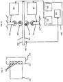
- brake modules 2 are shown and provided for operable interaction with a brake disk 4.
- the brake disk 4 is keyed to and rotatable with shaft 6 and the shaft 6 is provided as an extension of an elevator machine motor.
- Each of the brake modules 2 includes a brake assembly 8 and a brake latch assembly 10.
- the brake assembly 8 includes a bracket 12 which is fixed to machine frame 14 and to which two opposed brake arms 16 are mounted for pivotal movement about vertical pins 22.
- the pins 18 pass through lugs 17 on the brake shoes 20 and the lugs 17 are disposed above and below the brake arms 16.
- a brake shoe 20 is pivotally mounted on pins 22 to the brake arms 16 so as to flank the brake disk 4.
- a coil spring 24 is sandwiched between each brake shoe 20 and its respective brake arm 16 biases each brake shoe 20 about its respective pin 22 and against the inner end of an adjustable screw 23.
- the adjustable screw 23 is threaded into each brake arm 16 such that the brake pads 26 on the brake shoes 20 remain parallel to each other and to the brake disk 4.
- a brake actuating spring 28 is mounted in spring caps 30 that are carried on spring guides 32 secured to the brake arms 16.
- the brake actuating spring 28 biases the brake arms 16 outwardly about the pins 18 thereby biasing the brake shoes 20 against the brake disk 4. This action will occur whenever power is removed from the solenoid 36 so that in the event of a power failure or an emergency the brake pads 26 automatically sit on the brake disk 4.
- the brake actuating spring 28 supplies the force needed to set the brake pads 26.
- Cam pins 34 are mounted on the ends of the brake arms 16 at a location remote from the brake shoes 20.
- the brake latch assembly 10 includes a solenoid 36 with an energized coil which is fixed to the machine frame 14 and a solenoid actuated plunger 38 that moves up and down in the solenoid 36.
- Brackets 40 are mounted on opposite sides of the solenoid 36 and latch levers 42 with upturned fingers 43 are pivotally mounted on the brackets 40 via pins 44.
- a clevis 46 is disposed on the plunger 38 and receives overlapping ends 48 of the levers 42.
- a pin 50 spans the clevis 46 and overlies the ends 48 of the levers 42 thereby interconnecting the solenoid plunger 38 and the levers 42.
- the upturned fingers 43 on the levers 42 engage the cam pins 34 on the brake assembly 8.
- brake modules 2 of FIGS. 1-3 which are described above, can have various configurations and constructions and that the embodiments provided herein are merely examples of the same. Thus, it is to be understood that the brake modules 2 can have many different or other configurations and methods of operation. In any case, the following additional description will relate to the embodiments described herein but would be applicable to any brake modules in which a brake disk is employed.
- an elevator brake disk assembly 401 is provided for reducing noise generated by excitation of the brake disk 4 during running or operation of the elevator machine motor.
- the elevator brake disk assembly includes the brake disk 4, which is keyed to and rotatable with the shaft 6 (see FIG. 1 ) of the elevator machine as described above, the machine frame 14 (see FIG. 1 ) and first and second dampers 402 and 403.
- the first damper 402 and the second damper 403 oppose one another and are respectively anchored to the machine frame 14 by first elastic element 404 and second elastic element 405.
- the first damper 402 and the second damper 403 are thus biased by the first elastic element 404 and the second elastic element 405, respectively, to symmetrically hold opposite sides 406 and 407 of a periphery 408 of the brake disk 4 during rotations thereof.
- first damper 402 and the second damper 403 roll with the rotations of the brake disk 4
- engagement of the first damper 402 and the second damper 403 with the brake disk 4 generates negligible friction between the first damper 402 and the side 406 and between the second damper 403 and the side 407.
- the engagement of the first damper 402 and the second damper 403 with the brake disk 4 produces little to no noise at least as compared to surrounding noise producing components.
- each of the first damper 402 and the second damper 403 includes a base part 410, an elastic member 411 and a roller element 412.
- the elastic member 411 is coupled at a first end thereof to the base part 410 and at a second end thereof to the machine frame 14 to thus anchor the base part 410 to the machine frame 14 with a bias toward the brake disk 4.
- the roller element 412 is coupled with the base part 410 and is rotatable with the brake disk 4 relative to the base part 410.
- each of the first damper 402 and the second damper 403 may further include a roller bearing 420 by which the roller element 412 and the base part 410 are coupled.
- the roller bearing 420 may be provided, for example, as a ball bearing as permits nearly frictionless rotation of the roller element 412 relative to the base part 410.
- the brake disk 4 may be formed of cast iron or other metallic materials.
- the roller element 412 may be formed of metallic or polymeric materials. In any case, the roller element 412 may have a circumferentially curved and axially curved surface 430.
- the first damper 402 and the second damper 403 may be controllable to assume and move between respective first positions and respective second positions. At the respective first positions, the first damper 402 and the second damper 403 are disengaged from the brake disk 4. At the respective second positions, the first damper 402 and the second damper 403 are engaged with the opposite sides 406 and 407 of the brake disk 4 and biased to symmetrically hold the brake disk 4 during the rotations thereof.
- the elevator brake disk assembly 401 may further include a controller 440.
- the controller 440 includes a processing element 441, a memory unit 442 and a servo control unit 443.
- the memory unit 442 has executable instructions stored thereon, which, when executed, cause the processing element 441 to identify whether a condition of the brake disk 4 is or is not in effect and, if the condition is in effect, to issue an instruction to the servo control unit 443 to selectively cause the first damper 402 and the second damper 403 to move from the first positions to the second positions (or to permit the first damper 402 and the second damper 403 to remain in the first positions or to move from the second positions to the first positions if the condition is not in effect).
- the movements of the first damper 402 and the second damper 403 may be driven, for example, by actuators 450 that are actuated by servo elements 451.
- the actuators 450 may be provided as linear actuators, rotary actuators or any other type of actuators and may be operated by electro-mechanical or hydraulic actuation.
- the servo elements 451 are provided in signal communication with the servo control unit 443 of the controller 440 so that the servo elements 451 are controllable by the controller 440 to actuator the actuators 450.
- the elevator brake disk assembly 401 may include a brake disk noise sensor 460.
- the brake disk noise sensor 460 may be disposed proximate to the brake disk 4 such that noise produced by an excitation of the brake disk 4 is picked up by the brake disk noise sensor 460.
- the brake disk noise sensor 460 is coupled to the controller 440 such that data reflective of noise being picked up by the brake disk noise sensor 460 can be transmitted to the controller 440.
- the controller 440 is capable of receiving the data and determining on the basis of an analysis of that data whether a given, predefined condition of the brake disk 4 is in effect. That is, the controller 440 is able to determine whether a certain level of noise is being produced and, if so, to have the actuators 450 actuated so as to bring the first damper 402 and the second damper 403 into engagement with the brake disk 4.
- the controller 440 may be tuned so that any noise picked up by the brake disk node sensor 460 is sufficient to bring the first damper 402 and the second damper 403 into engagement with the brake disk 4.
- the controller 440 may be tuned to only do so when the noise level is at or above a predefined threshold. This predefined threshold may be modified manually or automatically over time.
- a method of operating the elevator brake disk assembly 401 includes operating an elevator machine to rotate the brake disk 4, sensing a parameter of the brake disk 4 during the rotations thereof (here, the parameter may be the noise produced as a result of brake disk 4 excitation), identifying whether a condition of the brake disk 4 is in effect from results of the sensing and selectively causing the first damper 402 and the second damper 403 to move between the respective first and second positions in accordance with the identifying of whether the condition is in effect.
- noise caused by the disk brake in an elevator machine can be reduced from about 90 decibels to about 70-80 decibels and, in some cases, to about 76 decibels without any substantial redesign of the elevator machine motor.
Claims (11)
- Ensemble disque de frein d'ascenseur (8), comprenant :un disque de frein (4) qui est claveté sur un arbre (6) d'une machine d'ascenseur et qui peut tourner avec celui-ci ;un châssis de machine (14) ; etdes amortisseurs (402, 403) qui sont respectivement ancrés au châssis de machine (14), dans lequel les amortisseurs comprennent des premier et second amortisseurs opposés (402, 403) ;dans lequel : les amortisseurs (402, 403) peuvent être commandés pour adopter des premières positions respectives et se déplacer entre elles, auxquelles les amortisseurs (402, 403) sont dégagés du disque de frein (4) et des secondes positions respectives auxquelles les amortisseurs (402, 403) sont sollicités pour maintenir symétriquement le disque de frein (4) pendant les rotations de celui-ci ; l'ensemble frein d'ascenseur (8) comprenant en outre un dispositif de commande (440) qui est configuré pour identifier un état du disque de frein (4) actif et pour amener sélectivement les amortisseurs (402, 403) à se déplacer entre les premières et secondes positions en conséquence,caractérisé en ce que l'ensemble disque de frein d'ascenseur (8) comporte en outre un capteur de bruit de disque de frein (460) disposé à proximité du disque de frein (4) de façon à capter le bruit produit par une excitation du disque de frein (4), dans lequel le capteur de bruit de disque de frein (460) est couplé au dispositif de commande (440) de sorte que des données reflétant le bruit capté par le capteur de bruit de disque de frein (460) sont transmises au dispositif de commande (440), et1 dans lequel le dispositif de commande (440) est conçu pour déterminer si un certain niveau de bruit est produit et, dans l'affirmative, le dispositif de commande (440) est en outre conçu de manière à ce que les actionneurs (450) des amortisseurs soient actionnés de façon à amener le premier amortisseur (402) et le second amortisseur (403) en prise avec le disque de frein (4).
- Ensemble disque de frein d'ascenseur (8) selon la revendication 1, dans lequel les amortisseurs (402, 403) maintiennent symétriquement une périphérie du disque de frein (4) .
- Ensemble disque de frein d'ascenseur (8) selon l'une quelconque des revendications 1 et 2, dans lequel les amortisseurs (402, 403) génèrent un frottement négligeable avec le disque de frein (4).
- Ensemble disque de frein d'ascenseur (8) selon l'une quelconque des revendications 1 à 3, dans lequel chacun des amortisseurs (402, 403) comprend :une base (410) ;un élément élastique (411) couplé à une première extrémité de celui-ci à la base (410) et à une seconde extrémité de celui-ci au châssis de machine (14) ; etun rouleau (412) qui peut tourner avec le disque de frein (4) par rapport à la base (410) et couplé à celle-ci.
- Ensemble disque de frein d'ascenseur (8) selon la revendication 4, dans lequel chacun des amortisseurs (402, 403) comprend en outre un palier à rouleaux (420) pour coupler le rouleau (412) et la base (410).
- Ensemble disque de frein d'ascenseur (8) selon la revendication 4 ou 5, dans lequel le rouleau (412) a une surface incurvée pour entrer en contact avec une surface complémentaire du disque de frein (4).
- Ensemble disque de frein d'ascenseur (8) selon l'une quelconque des revendications 4 à 6, dans lequel chaque actionneur (450) est configuré pour déplacer le rouleau (412) vers ou à distance du disque de frein (4).
- Ensemble disque de frein d'ascenseur (8) selon l'une quelconque des revendications 4 à 7, dans lequel chacun des amortisseurs (402, 403) comprend en outre un élément d'asservissement qui peut être commandé par le dispositif de commande (440) pour actionner l'actionneur (450).
- Ensemble disque de frein d'ascenseur (8) selon l'une quelconque des revendications 1 à 8, dans lequel le dispositif de commande (440) comprend le capteur de bruit de disque de frein (460).
- Procédé de fonctionnement d'un ensemble disque de frein d'ascenseur (8) selon l'une quelconque des revendications 1 à 9, le procédé comprenant :le fonctionnement d'une machine d'ascenseur pour faire tourner un disque de frein (4) ;la détection d'un paramètre du disque de frein (4) pendant les rotations de celui-ci ;le fait d'identifier si un état du disque de frein (4) est actif à partir des résultats de la détection ; etle fait d'amener sélectivement les amortisseurs (402, 403) qui peuvent être respectivement commandés à adopter des premières et secondes positions respectives et à se déplacer entre elles, afin de se déplacer entre les premières et secondes positions conformément au fait d'identifier si l'état est actif,dans lequel, aux premières positions respectives, les amortisseurs (402, 403) sont dégagés du disque de frein (4) et, aux secondes positions respectives, les amortisseurs (402, 403) sont sollicités pour maintenir symétriquement le disque de frein (4) pendant les rotations de celui-ci,caractérisé en ce que la détection du paramètre comprend la détection du bruit généré par le disque de frein pendant les rotations de celui-ci.
- Procédé selon la revendication 10, dans lequel le fait d'identifier si l'état est actif comprend la détermination que le bruit généré par le disque de frein (4) pendant les rotations de celui-ci dépasse un niveau prédéfini.
Applications Claiming Priority (1)
| Application Number | Priority Date | Filing Date | Title |
|---|---|---|---|
| US15/403,835 US10214382B2 (en) | 2017-01-11 | 2017-01-11 | Disk damping device |
Publications (2)
| Publication Number | Publication Date |
|---|---|
| EP3348854A1 EP3348854A1 (fr) | 2018-07-18 |
| EP3348854B1 true EP3348854B1 (fr) | 2020-07-01 |
Family
ID=60953759
Family Applications (1)
| Application Number | Title | Priority Date | Filing Date |
|---|---|---|---|
| EP18150941.5A Active EP3348854B1 (fr) | 2017-01-11 | 2018-01-10 | Dispositif d'amortissement de disque |
Country Status (3)
| Country | Link |
|---|---|
| US (1) | US10214382B2 (fr) |
| EP (1) | EP3348854B1 (fr) |
| CN (1) | CN108313916B (fr) |
Families Citing this family (3)
| Publication number | Priority date | Publication date | Assignee | Title |
|---|---|---|---|---|
| EP4077191A1 (fr) * | 2019-12-16 | 2022-10-26 | Otis Elevator Company | Dispositif de guidage pour cabine d'ascenseur et système d'ascenseur |
| US11780715B2 (en) * | 2020-03-16 | 2023-10-10 | Wenger Corporation | Hoist brake |
| CN114436095A (zh) * | 2020-11-02 | 2022-05-06 | 奥的斯电梯公司 | 滚轮系统、滚轮制动装置及电梯系统 |
Family Cites Families (21)
| Publication number | Priority date | Publication date | Assignee | Title |
|---|---|---|---|---|
| US915936A (en) | 1903-06-06 | 1909-03-23 | Victor Talking Machine Co | Reproducing-stylus for talking-machines. |
| US4796728A (en) | 1986-05-05 | 1989-01-10 | Austoft Inc. (U.S.A.) | Brake noise reduction system |
| US5101939A (en) | 1990-04-13 | 1992-04-07 | Otis Elevator Company | Disk brake for elevator |
| CN1240504A (zh) * | 1996-12-12 | 2000-01-05 | 联盟-莫卧技术有限公司 | 盘状制动系统 |
| JPH11171440A (ja) | 1997-12-10 | 1999-06-29 | Mitsubishi Electric Corp | エレベーター巻上機用ブレーキ装置 |
| EP0957281A3 (fr) | 1998-05-14 | 2001-06-27 | SEW-EURODRIVE GMBH & CO. | Frein à actionnement électromagnétique en particulier pour moteur électrique |
| US6155390A (en) | 1998-06-04 | 2000-12-05 | Russell Ozechowski | Incremental braking interface between shoe and drum or caliper and rotor and method of braking |
| KR100482093B1 (ko) | 2002-07-04 | 2005-04-13 | 현대자동차주식회사 | 롤러 패드를 이용한 디스크 브레이크 장치 |
| JP2004076913A (ja) * | 2002-08-22 | 2004-03-11 | Mitsubishi Electric Corp | 巻上機用ディスクブレーキ |
| EP1809561A1 (fr) | 2004-11-01 | 2007-07-25 | Otis Elevator Company | Frein a disque d'ascenseur a amortissement |
| JP4846297B2 (ja) * | 2005-08-03 | 2011-12-28 | Ntn株式会社 | ブレーキディスクの制動面加工装置 |
| US8151950B2 (en) | 2006-04-17 | 2012-04-10 | Otis Elevator Company | Permanent magnet elevator disk brake |
| US20090032340A1 (en) * | 2007-07-31 | 2009-02-05 | Rory Smith | Method and Apparatus to Minimize Re-Leveling in High Rise High Speed Elevators |
| US9376295B2 (en) * | 2007-12-10 | 2016-06-28 | Otis Elevator Company | Elevator brake device including permanent magnet bias to apply a braking force |
| FI121994B (fi) * | 2009-09-25 | 2011-07-15 | Kone Corp | Koneistojarru |
| US20120031715A1 (en) | 2010-08-03 | 2012-02-09 | Conway Edward R | Industrial motor braking system |
| BR112013002975A2 (pt) * | 2010-08-06 | 2018-07-03 | Coreeelevator Co Ltd | parte de acionamento com formato de engrenagem de rosca sem fim, elevador com o uso de parte de acionamento com formato de engrenagem de rosca sem fim e sistema de elevação |
| FI125108B (fi) | 2011-05-12 | 2015-06-15 | Kone Corp | Jarru sekä menetelmä jarrun valmistamiseksi |
| CN202082377U (zh) * | 2011-05-20 | 2011-12-21 | 浙江锯力煌锯床股份有限公司 | 减速机刹车式阻尼消隙装置 |
| DE102011053178B3 (de) * | 2011-08-31 | 2012-11-29 | Klaus-Peter Kapp | Reibungsbremse mit einer senkrecht zur Zuspannrichtung wirkenden Aktoreinheit |
| CN104176674A (zh) * | 2013-05-24 | 2014-12-03 | 浙江法斯特电梯有限公司 | 一种电梯制动器 |
-
2017
- 2017-01-11 US US15/403,835 patent/US10214382B2/en active Active
-
2018
- 2018-01-10 CN CN201810024676.2A patent/CN108313916B/zh active Active
- 2018-01-10 EP EP18150941.5A patent/EP3348854B1/fr active Active
Non-Patent Citations (1)
| Title |
|---|
| None * |
Also Published As
| Publication number | Publication date |
|---|---|
| CN108313916A (zh) | 2018-07-24 |
| US20180194593A1 (en) | 2018-07-12 |
| CN108313916B (zh) | 2021-02-09 |
| US10214382B2 (en) | 2019-02-26 |
| EP3348854A1 (fr) | 2018-07-18 |
Similar Documents
| Publication | Publication Date | Title |
|---|---|---|
| JP5212971B2 (ja) | ブレーキ装置、エレベータ装置、ブレーキ装置の機能を検出するための方法、および最新化セット | |
| RU2607906C2 (ru) | Ловитель лифта | |
| EP3348854B1 (fr) | Dispositif d'amortissement de disque | |
| US20170240381A1 (en) | Elevator braking system | |
| US8186483B2 (en) | Elevator braking device | |
| RU2472693C2 (ru) | Блок контроля скорости и ускорения с управляемым электронным способом пусковым сервомеханизмом для применения в подъемно-транспортных средствах | |
| FI125889B (fi) | Jarru ja hissijärjestelmä | |
| US20110226560A1 (en) | Elevator braking equipment | |
| US10501287B2 (en) | Damper unit for an elevator | |
| JPWO2009040934A1 (ja) | エレベータの安全装置 | |
| US20120305338A1 (en) | Regulable elevator brake | |
| US7374021B2 (en) | Combined elevator guiding and safety braking device | |
| CN113167347B (zh) | 制动组件和用于控制制动组件的方法 | |
| JP2000211841A (ja) | エレベ―タ装置の動きを停止させる装置 | |
| WO2004033354A1 (fr) | Dispositif de securite d'ascenseur | |
| JP6793603B2 (ja) | エレベーターの非常止め起動装置 | |
| CN111377333A (zh) | 电梯轿厢停驻制动器 | |
| EP1549582B1 (fr) | Dispositif combine de guidage et de freinage de securite d'ascenseur | |
| KR20170122264A (ko) | 엘리베이터 시스템의 카를 위한 브레이크 장치 | |
| CN109775508B (zh) | 紧急制动装置及具有该紧急制动装置的电梯系统 | |
| JP2010508161A (ja) | 工作機械、生産機械ないしメンテナンス機械 | |
| JP2012066907A (ja) | エレベーターの制動装置及びそれを用いたエレベーター装置 | |
| JP4601150B2 (ja) | エレベーター用巻上機装置 | |
| EP2296849B1 (fr) | Dispositif pour commander un mouvement d'actionnement d'un actionneur et actionneur comportant le dispositif | |
| JP2017105597A (ja) | エレベーター装置 |
Legal Events
| Date | Code | Title | Description |
|---|---|---|---|
| PUAI | Public reference made under article 153(3) epc to a published international application that has entered the european phase |
Free format text: ORIGINAL CODE: 0009012 |
|
| STAA | Information on the status of an ep patent application or granted ep patent |
Free format text: STATUS: THE APPLICATION HAS BEEN PUBLISHED |
|
| AK | Designated contracting states |
Kind code of ref document: A1 Designated state(s): AL AT BE BG CH CY CZ DE DK EE ES FI FR GB GR HR HU IE IS IT LI LT LU LV MC MK MT NL NO PL PT RO RS SE SI SK SM TR |
|
| AX | Request for extension of the european patent |
Extension state: BA ME |
|
| STAA | Information on the status of an ep patent application or granted ep patent |
Free format text: STATUS: REQUEST FOR EXAMINATION WAS MADE |
|
| 17P | Request for examination filed |
Effective date: 20190116 |
|
| RBV | Designated contracting states (corrected) |
Designated state(s): AL AT BE BG CH CY CZ DE DK EE ES FI FR GB GR HR HU IE IS IT LI LT LU LV MC MK MT NL NO PL PT RO RS SE SI SK SM TR |
|
| STAA | Information on the status of an ep patent application or granted ep patent |
Free format text: STATUS: EXAMINATION IS IN PROGRESS |
|
| 17Q | First examination report despatched |
Effective date: 20190923 |
|
| GRAP | Despatch of communication of intention to grant a patent |
Free format text: ORIGINAL CODE: EPIDOSNIGR1 |
|
| STAA | Information on the status of an ep patent application or granted ep patent |
Free format text: STATUS: GRANT OF PATENT IS INTENDED |
|
| INTG | Intention to grant announced |
Effective date: 20200211 |
|
| GRAS | Grant fee paid |
Free format text: ORIGINAL CODE: EPIDOSNIGR3 |
|
| GRAA | (expected) grant |
Free format text: ORIGINAL CODE: 0009210 |
|
| STAA | Information on the status of an ep patent application or granted ep patent |
Free format text: STATUS: THE PATENT HAS BEEN GRANTED |
|
| AK | Designated contracting states |
Kind code of ref document: B1 Designated state(s): AL AT BE BG CH CY CZ DE DK EE ES FI FR GB GR HR HU IE IS IT LI LT LU LV MC MK MT NL NO PL PT RO RS SE SI SK SM TR |
|
| REG | Reference to a national code |
Ref country code: AT Ref legal event code: REF Ref document number: 1286475 Country of ref document: AT Kind code of ref document: T Effective date: 20200715 Ref country code: CH Ref legal event code: EP |
|
| REG | Reference to a national code |
Ref country code: IE Ref legal event code: FG4D |
|
| REG | Reference to a national code |
Ref country code: DE Ref legal event code: R096 Ref document number: 602018005594 Country of ref document: DE |
|
| REG | Reference to a national code |
Ref country code: LT Ref legal event code: MG4D |
|
| PG25 | Lapsed in a contracting state [announced via postgrant information from national office to epo] |
Ref country code: BG Free format text: LAPSE BECAUSE OF FAILURE TO SUBMIT A TRANSLATION OF THE DESCRIPTION OR TO PAY THE FEE WITHIN THE PRESCRIBED TIME-LIMIT Effective date: 20201001 |
|
| REG | Reference to a national code |
Ref country code: NL Ref legal event code: MP Effective date: 20200701 |
|
| REG | Reference to a national code |
Ref country code: AT Ref legal event code: MK05 Ref document number: 1286475 Country of ref document: AT Kind code of ref document: T Effective date: 20200701 |
|
| PG25 | Lapsed in a contracting state [announced via postgrant information from national office to epo] |
Ref country code: AT Free format text: LAPSE BECAUSE OF FAILURE TO SUBMIT A TRANSLATION OF THE DESCRIPTION OR TO PAY THE FEE WITHIN THE PRESCRIBED TIME-LIMIT Effective date: 20200701 Ref country code: CZ Free format text: LAPSE BECAUSE OF FAILURE TO SUBMIT A TRANSLATION OF THE DESCRIPTION OR TO PAY THE FEE WITHIN THE PRESCRIBED TIME-LIMIT Effective date: 20200701 Ref country code: FI Free format text: LAPSE BECAUSE OF FAILURE TO SUBMIT A TRANSLATION OF THE DESCRIPTION OR TO PAY THE FEE WITHIN THE PRESCRIBED TIME-LIMIT Effective date: 20200701 Ref country code: HR Free format text: LAPSE BECAUSE OF FAILURE TO SUBMIT A TRANSLATION OF THE DESCRIPTION OR TO PAY THE FEE WITHIN THE PRESCRIBED TIME-LIMIT Effective date: 20200701 Ref country code: LT Free format text: LAPSE BECAUSE OF FAILURE TO SUBMIT A TRANSLATION OF THE DESCRIPTION OR TO PAY THE FEE WITHIN THE PRESCRIBED TIME-LIMIT Effective date: 20200701 Ref country code: PT Free format text: LAPSE BECAUSE OF FAILURE TO SUBMIT A TRANSLATION OF THE DESCRIPTION OR TO PAY THE FEE WITHIN THE PRESCRIBED TIME-LIMIT Effective date: 20201102 Ref country code: SE Free format text: LAPSE BECAUSE OF FAILURE TO SUBMIT A TRANSLATION OF THE DESCRIPTION OR TO PAY THE FEE WITHIN THE PRESCRIBED TIME-LIMIT Effective date: 20200701 Ref country code: GR Free format text: LAPSE BECAUSE OF FAILURE TO SUBMIT A TRANSLATION OF THE DESCRIPTION OR TO PAY THE FEE WITHIN THE PRESCRIBED TIME-LIMIT Effective date: 20201002 Ref country code: ES Free format text: LAPSE BECAUSE OF FAILURE TO SUBMIT A TRANSLATION OF THE DESCRIPTION OR TO PAY THE FEE WITHIN THE PRESCRIBED TIME-LIMIT Effective date: 20200701 Ref country code: NO Free format text: LAPSE BECAUSE OF FAILURE TO SUBMIT A TRANSLATION OF THE DESCRIPTION OR TO PAY THE FEE WITHIN THE PRESCRIBED TIME-LIMIT Effective date: 20201001 |
|
| PG25 | Lapsed in a contracting state [announced via postgrant information from national office to epo] |
Ref country code: IS Free format text: LAPSE BECAUSE OF FAILURE TO SUBMIT A TRANSLATION OF THE DESCRIPTION OR TO PAY THE FEE WITHIN THE PRESCRIBED TIME-LIMIT Effective date: 20201101 Ref country code: LV Free format text: LAPSE BECAUSE OF FAILURE TO SUBMIT A TRANSLATION OF THE DESCRIPTION OR TO PAY THE FEE WITHIN THE PRESCRIBED TIME-LIMIT Effective date: 20200701 Ref country code: PL Free format text: LAPSE BECAUSE OF FAILURE TO SUBMIT A TRANSLATION OF THE DESCRIPTION OR TO PAY THE FEE WITHIN THE PRESCRIBED TIME-LIMIT Effective date: 20200701 Ref country code: RS Free format text: LAPSE BECAUSE OF FAILURE TO SUBMIT A TRANSLATION OF THE DESCRIPTION OR TO PAY THE FEE WITHIN THE PRESCRIBED TIME-LIMIT Effective date: 20200701 |
|
| PG25 | Lapsed in a contracting state [announced via postgrant information from national office to epo] |
Ref country code: NL Free format text: LAPSE BECAUSE OF FAILURE TO SUBMIT A TRANSLATION OF THE DESCRIPTION OR TO PAY THE FEE WITHIN THE PRESCRIBED TIME-LIMIT Effective date: 20200701 |
|
| REG | Reference to a national code |
Ref country code: DE Ref legal event code: R097 Ref document number: 602018005594 Country of ref document: DE |
|
| PG25 | Lapsed in a contracting state [announced via postgrant information from national office to epo] |
Ref country code: DK Free format text: LAPSE BECAUSE OF FAILURE TO SUBMIT A TRANSLATION OF THE DESCRIPTION OR TO PAY THE FEE WITHIN THE PRESCRIBED TIME-LIMIT Effective date: 20200701 Ref country code: RO Free format text: LAPSE BECAUSE OF FAILURE TO SUBMIT A TRANSLATION OF THE DESCRIPTION OR TO PAY THE FEE WITHIN THE PRESCRIBED TIME-LIMIT Effective date: 20200701 Ref country code: EE Free format text: LAPSE BECAUSE OF FAILURE TO SUBMIT A TRANSLATION OF THE DESCRIPTION OR TO PAY THE FEE WITHIN THE PRESCRIBED TIME-LIMIT Effective date: 20200701 Ref country code: SM Free format text: LAPSE BECAUSE OF FAILURE TO SUBMIT A TRANSLATION OF THE DESCRIPTION OR TO PAY THE FEE WITHIN THE PRESCRIBED TIME-LIMIT Effective date: 20200701 Ref country code: IT Free format text: LAPSE BECAUSE OF FAILURE TO SUBMIT A TRANSLATION OF THE DESCRIPTION OR TO PAY THE FEE WITHIN THE PRESCRIBED TIME-LIMIT Effective date: 20200701 |
|
| PLBE | No opposition filed within time limit |
Free format text: ORIGINAL CODE: 0009261 |
|
| STAA | Information on the status of an ep patent application or granted ep patent |
Free format text: STATUS: NO OPPOSITION FILED WITHIN TIME LIMIT |
|
| PG25 | Lapsed in a contracting state [announced via postgrant information from national office to epo] |
Ref country code: AL Free format text: LAPSE BECAUSE OF FAILURE TO SUBMIT A TRANSLATION OF THE DESCRIPTION OR TO PAY THE FEE WITHIN THE PRESCRIBED TIME-LIMIT Effective date: 20200701 |
|
| 26N | No opposition filed |
Effective date: 20210406 |
|
| PG25 | Lapsed in a contracting state [announced via postgrant information from national office to epo] |
Ref country code: SK Free format text: LAPSE BECAUSE OF FAILURE TO SUBMIT A TRANSLATION OF THE DESCRIPTION OR TO PAY THE FEE WITHIN THE PRESCRIBED TIME-LIMIT Effective date: 20200701 |
|
| PG25 | Lapsed in a contracting state [announced via postgrant information from national office to epo] |
Ref country code: MC Free format text: LAPSE BECAUSE OF FAILURE TO SUBMIT A TRANSLATION OF THE DESCRIPTION OR TO PAY THE FEE WITHIN THE PRESCRIBED TIME-LIMIT Effective date: 20200701 Ref country code: SI Free format text: LAPSE BECAUSE OF FAILURE TO SUBMIT A TRANSLATION OF THE DESCRIPTION OR TO PAY THE FEE WITHIN THE PRESCRIBED TIME-LIMIT Effective date: 20200701 |
|
| REG | Reference to a national code |
Ref country code: CH Ref legal event code: PL |
|
| PG25 | Lapsed in a contracting state [announced via postgrant information from national office to epo] |
Ref country code: LU Free format text: LAPSE BECAUSE OF NON-PAYMENT OF DUE FEES Effective date: 20210110 |
|
| REG | Reference to a national code |
Ref country code: BE Ref legal event code: MM Effective date: 20210131 |
|
| PG25 | Lapsed in a contracting state [announced via postgrant information from national office to epo] |
Ref country code: LI Free format text: LAPSE BECAUSE OF NON-PAYMENT OF DUE FEES Effective date: 20210131 Ref country code: CH Free format text: LAPSE BECAUSE OF NON-PAYMENT OF DUE FEES Effective date: 20210131 |
|
| PG25 | Lapsed in a contracting state [announced via postgrant information from national office to epo] |
Ref country code: IE Free format text: LAPSE BECAUSE OF NON-PAYMENT OF DUE FEES Effective date: 20210110 |
|
| PG25 | Lapsed in a contracting state [announced via postgrant information from national office to epo] |
Ref country code: BE Free format text: LAPSE BECAUSE OF NON-PAYMENT OF DUE FEES Effective date: 20210131 |
|
| GBPC | Gb: european patent ceased through non-payment of renewal fee |
Effective date: 20220110 |
|
| PG25 | Lapsed in a contracting state [announced via postgrant information from national office to epo] |
Ref country code: GB Free format text: LAPSE BECAUSE OF NON-PAYMENT OF DUE FEES Effective date: 20220110 |
|
| PG25 | Lapsed in a contracting state [announced via postgrant information from national office to epo] |
Ref country code: CY Free format text: LAPSE BECAUSE OF FAILURE TO SUBMIT A TRANSLATION OF THE DESCRIPTION OR TO PAY THE FEE WITHIN THE PRESCRIBED TIME-LIMIT Effective date: 20200701 |
|
| PG25 | Lapsed in a contracting state [announced via postgrant information from national office to epo] |
Ref country code: HU Free format text: LAPSE BECAUSE OF FAILURE TO SUBMIT A TRANSLATION OF THE DESCRIPTION OR TO PAY THE FEE WITHIN THE PRESCRIBED TIME-LIMIT; INVALID AB INITIO Effective date: 20180110 |
|
| PGFP | Annual fee paid to national office [announced via postgrant information from national office to epo] |
Ref country code: FR Payment date: 20231219 Year of fee payment: 7 |
|
| PG25 | Lapsed in a contracting state [announced via postgrant information from national office to epo] |
Ref country code: MK Free format text: LAPSE BECAUSE OF FAILURE TO SUBMIT A TRANSLATION OF THE DESCRIPTION OR TO PAY THE FEE WITHIN THE PRESCRIBED TIME-LIMIT Effective date: 20200701 |
|
| PGFP | Annual fee paid to national office [announced via postgrant information from national office to epo] |
Ref country code: DE Payment date: 20231219 Year of fee payment: 7 |