EP3348726A1 - Wärmedämmvorrichtung insbesondere zur wärmedämmung von gebäuden oder gebäudeteilen - Google Patents
Wärmedämmvorrichtung insbesondere zur wärmedämmung von gebäuden oder gebäudeteilen Download PDFInfo
- Publication number
- EP3348726A1 EP3348726A1 EP18150948.0A EP18150948A EP3348726A1 EP 3348726 A1 EP3348726 A1 EP 3348726A1 EP 18150948 A EP18150948 A EP 18150948A EP 3348726 A1 EP3348726 A1 EP 3348726A1
- Authority
- EP
- European Patent Office
- Prior art keywords
- heat
- insulating
- thermal insulation
- insulating device
- parts
- Prior art date
- Legal status (The legal status is an assumption and is not a legal conclusion. Google has not performed a legal analysis and makes no representation as to the accuracy of the status listed.)
- Withdrawn
Links
- 238000009413 insulation Methods 0.000 title claims abstract description 112
- 230000000295 complement effect Effects 0.000 claims description 5
- 150000001875 compounds Chemical class 0.000 claims 1
- 239000002131 composite material Substances 0.000 description 9
- 238000009415 formwork Methods 0.000 description 7
- 238000011161 development Methods 0.000 description 4
- 230000018109 developmental process Effects 0.000 description 4
- 239000012212 insulator Substances 0.000 description 4
- 239000000463 material Substances 0.000 description 4
- 239000011505 plaster Substances 0.000 description 4
- 238000009434 installation Methods 0.000 description 3
- 238000004519 manufacturing process Methods 0.000 description 3
- 230000006978 adaptation Effects 0.000 description 2
- 239000000853 adhesive Substances 0.000 description 2
- 230000001070 adhesive effect Effects 0.000 description 2
- 238000010276 construction Methods 0.000 description 2
- 239000006260 foam Substances 0.000 description 2
- 239000004570 mortar (masonry) Substances 0.000 description 2
- 230000001419 dependent effect Effects 0.000 description 1
- 229920006248 expandable polystyrene Polymers 0.000 description 1
- 239000011810 insulating material Substances 0.000 description 1
- 238000004091 panning Methods 0.000 description 1
- 239000004033 plastic Substances 0.000 description 1
- 230000000284 resting effect Effects 0.000 description 1
- 238000009966 trimming Methods 0.000 description 1
- 239000002699 waste material Substances 0.000 description 1
Images



Classifications
-
- E—FIXED CONSTRUCTIONS
- E04—BUILDING
- E04B—GENERAL BUILDING CONSTRUCTIONS; WALLS, e.g. PARTITIONS; ROOFS; FLOORS; CEILINGS; INSULATION OR OTHER PROTECTION OF BUILDINGS
- E04B1/00—Constructions in general; Structures which are not restricted either to walls, e.g. partitions, or floors or ceilings or roofs
- E04B1/62—Insulation or other protection; Elements or use of specified material therefor
- E04B1/74—Heat, sound or noise insulation, absorption, or reflection; Other building methods affording favourable thermal or acoustical conditions, e.g. accumulating of heat within walls
- E04B1/76—Heat, sound or noise insulation, absorption, or reflection; Other building methods affording favourable thermal or acoustical conditions, e.g. accumulating of heat within walls specifically with respect to heat only
- E04B1/762—Exterior insulation of exterior walls
Definitions
- the present invention relates to a thermal insulation device according to the preamble of patent claim 1.
- Thermal insulation devices for buildings have been known for many years in innumerable embodiments.
- thermal insulation devices include the thermal insulation panels of a thermal insulation composite system. Using such thermal insulation panels, the outer walls of a building can be relatively quickly and easily provided with a very effective thermal insulation.
- almost all buildings have various parts of the building whose thermal insulation requires a disproportionate effort. This includes, for example, the exterior wall area of a building adjoining the eaves with a sloping roof projecting laterally.
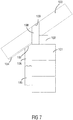
- FIG. 7 shows a portion of a building exterior wall formed by a wall 101 and a part of the roof of the building. From the roof are in the FIG. 7 a (roof) purlin 102, a (roof) rafter 103, and provided in the eaves area on the underside of the rafters 103 eaves formwork 104 is shown.
- the purlin 102 is a foot purlin which rests centrally on the wall 101 (or a ring anchor mounted above) and serves as a support for the rafters 103 resting thereon.
- the outside of the wall 101 is clad using a composite thermal insulation system. Thermal insulation composite system thermal insulation panels 105 and 106 are shown.
- the lower thermal insulation panel 105 is a "normal" thermal insulation panel, which must have only the correct length and width.
- the upper thermal insulation panel 106 extends up to the obliquely downwardly extending eaves formwork 104 upwards and must have at its upper end a slope 107, the slope of the Traufschalung 104 corresponds, so that the slope 107 of the thermal insulation board 106 over the entire surface of the eaves formwork 204 comes into contact. Since the slant 107 to be provided may vary from building to building, in most cases it is necessary to tailor the thermal insulation panels 106 individually at the construction site. This is obviously associated with a very large effort. Moreover, even with great care, there is a considerable risk that the thermal insulation panels 106 still do not optimally fit in the gap to be filled.
- thermal insulation device also referred to as purlin insulation.
- a thermal insulation device is also in the FIG. 7 shown and designated there by the reference numeral 108.
- the thermal insulation device 108 is used to close an existing opening in the building in the building. The said opening is down through the top of the purlin 102, up through the mounted on the top of the rafters 103, in the FIG. 7 Not shown formwork, and bounded to the side by two adjacent rafters 103.
- the thermal insulation device 108 used to close such an opening may rest on the wall 101, more precisely in which the outer wall section adjacent to the purlin 102 rests and extends up to the aforementioned formwork. This area has hitherto been closed with masonry blocks or with thermal insulation boards.
- thermal insulation device 108 adapted to the roof inclination slope 109 must be formed, which rests over the entire surface of the provided on the rafter top formwork. Consequently, the same problems and risks occur as in the production of the thermal insulation panel 106.
- the present invention is therefore based on the object to find a way by which thermal insulation devices that must have an individually adapted to the prevailing conditions slope or other labor-intensive Require adjustments, make it quick and easy.
- the thermal insulation device according to the invention is characterized in that it comprises a first heat-insulating member part and a second heat-insulating member part, which are engageable with each other so that they are pivotally relative to each other in the intended mutually engaged state.
- the thermal insulation device according to the invention makes it possible, for example, to align the second part of the thermal insulation device by pivoting it as desired in relation to the part of the building with which it must come into contact. More specifically, it can be achieved only by a corresponding pivoting and in particular without an individual cut of the second heat-insulating part, that a certain surface of the second heat-insulating member is aligned parallel to the surface of the building, with which it must come into contact.
- a third heat-insulating part is additionally provided, which can be connected to the first part of the heat-insulating device such that these heat-insulating device parts can be telescoped and pulled apart as intended and without any solution of the connection.
- the first heat-insulating part can be positioned with little effort so that the second part of the thermal insulation device can be made even easier and more accurate in its intended location.
- the thermal insulation device according to the invention can therefore be much faster and easier individually adapted to the prevailing conditions than is the case with conventional thermal insulation devices.
- the thermal insulation device described in more detail below is a thermal insulation device, in particular for thermal insulation of buildings or parts of buildings.
- the described thermal insulation device can be used for various purposes. In the following, in particular the use of the thermal insulation device as Pfettendämmung and as a similarly trained part of a thermal insulation composite system is described in detail. However, it should be noted at this point that the use of the thermal insulation device presented here is not limited thereto.
- the thermal insulation device can also be used for other purposes on buildings or parts of buildings, and can also be used for thermal insulation of any other objects, so not only for the thermal insulation of buildings and parts of buildings.
- the thermal insulation device presented here is used as Pfettendämmung.
- the FIG. 1 shows a part of a building exterior wall formed by a wall 1 and a part of the roof of the building. From the roof are in the FIG. 1 a (roof) purlin 2 and a (roof) rafter 3 shown.
- the wall 1, the purlin 2 and the rafters 3 correspond to those in the FIG. 7 designated by the reference numerals 101, 102, and 103 components. These components will therefore not be described again here; To avoid repetition will be on the on the FIG. 7 reference description referenced.
- the thermal insulation used as purlin insulation is in the FIG. 1 denoted by the reference numeral 8.
- the thermal insulation device 8 is installed in the same place, closes the same opening in the building, and has the same function as in the FIG. 7
- the structure of the thermal insulation device 8 differs very significantly from the conventional purlin insulation 108 shown and described with reference thereto.
- thermal insulation device 8 presented here is particularly in the FIGS. 2 and 3 good to see.
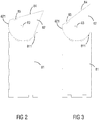
- the heat-insulating device 8 includes a plurality of component parts, more specifically, a first heat-insulating member 81 and a second heat-insulating member 82. These heat-insulating members 81, 82 are engageable with each other so as to be properly engaged with each other are pivotable relative to each other.
- FIGS. 2 and 3 show the heat-insulating parts 81, 82 in the intended mutually engaged state. It is such that the first heat-insulating member 81 has a recess 811 on its side facing the second heat-insulating member 82, and the second heat-insulating member 82 on its side facing the first heat-insulating member 81 is complementary to the recess 811 Survey 821 has.
- the recess and the protrusion may also be interchanged, so that the second heat-insulating member 82 may have a recess on its side facing the first heat-insulating member 81, and the first heat-insulating member may face on the second heat-insulating member Side may have a complementary trained to the recess survey.
- the first heat-insulating member 81 and the second heat-insulating member 82 are engaged with each other by inserting the protrusion 821 in the recess 811.
- the recess 811 and the elevation 821 are formed such that the heat-insulating device parts 81, 82 are pivotable about a predetermined virtual pivot axis 83, preferably only about this pivot axis 83 relative to each other.
- FIGS. 2 and 3 show two different pivot positions of the heat-insulating parts 81, 82.
- thermal insulation device aligned with the heat-insulating device parts 81, 82, so are not pivoted relative to each other.
- the heat-insulating parts 81, 82 in the FIG. 1 shown purlin insulation 8.
- This relative position or this swivel angle between the heat-insulating parts 81, 82 was in the in the FIG. 1 chosen arrangement, because in this state, a surface 84 of the second heat-insulating member portion 82 over the entire surface of the roof component abuts, to which it is to extend.
- the said surface of the second heat-insulating member 82 is a bevel 84 provided at the front end, that is, at the end of the second heat-insulating member 82 remote from the first heat-insulating member 81.
- the slope 84 of the second Heat-insulating part 82 abuts the entire surface of said roof component.
- the second piece of thermal insulation device 82 When in the FIG. 2 shown relative position of the heat-insulating parts 81, 82, the second piece of thermal insulation device 82 a piece to the right (relative to in the FIG. 1 shown installation position further to the building) pivoted. As a result, the slope 84 is less steep and could come into full contact with a correspondingly flatter roof.
- the slope 84 would be steeper and could come into contact with a correspondingly steeper roof over its entire surface.
- the second heat sink portion 82 may be placed in such a position that a particular surface thereof is aligned parallel to the building portion to which it is oriented should extend, and in this orientation, the said surface, the second heat-insulating member portion 82 with the relevant part of the building come into contact over its entire surface.
- This can be achieved solely by a corresponding pivoting of the second heat-insulating device part 82.
- An additional processing of the wide heat-insulating device part 82 for example, an individual cutting of the same can be omitted.
- Trimming the second heat sink portion 82 or other adjustments may still prove advantageous under certain circumstances.
- the mentioned pivoting of the heat-insulating parts 81, 82 makes namely readjustments possible, so that the cutting or the other operations do not require high precision, so can be done quickly and easily.
- the bevel 84 mentioned above is in the area of the second heat-insulating device part 82, which should preferably come into full contact with the building part up to which the second heat-insulating device part 82 should extend. In principle, however, it could also be to act on any other surface of the second heat sink portion 82.
- a recess 85 is provided which extends over the entire length of the slope 84.
- the recess 85 is designed to receive a Kompribandes, which ensures that any existing leaks between the slope 84 and the building part, with which the slope 84 is to come into contact, are hermetically sealed.
- the recess 811 has no undercut, so that in the mutually engaged state of the heat-insulating parts 81, 82, the second heat-insulating parts 82, more precisely its elevation 821 only loosely in the recess 811 and not otherwise on the first Heat-insulating member part 81 is held.
- a connection between the heat-insulating parts 81, 82 may be provided.
- the recess 811 extends parallel to the virtual pivot axis 83 and extends over the entire side of the heat-insulating part on which it is provided. The same applies to the associated elevation 821. This also runs parallel to the virtual pivot axis 83 and extends over the entire side of the heat-insulating part on which it is provided.
- the recess 811 has in the example considered a circular segment-shaped cross-section.
- the elevation 821 has a corresponding complementary cross-section.
- the components of the heat-insulator parts 81, 82 which are to be brought into engagement with each other can, in principle, also be designed in any other way and / or be brought into engagement with each other in any other way.
- the heat sink parts 81, 82 are properly engaged with each other regardless of their intended purpose Relative position no air gap between the two heat-insulating parts 81, 82 is present and therefore no air between the two heat-insulating parts 81, 82 can pass.
- the second heat-insulating member portion 82 is formed less thick than the first heat-insulating member portion 81. Then, in certain installation conditions, larger pivotal movements can be performed (see, for example FIG. 6 ).
- the first heat-insulating member 81 is formed in the example considered by a plate. This may essentially be a normal thermal insulation board, as used in the known thermal insulation systems. The only particularity is that it must be engaged with the second heat sink portion 82 as described.
- the second heat-insulating member 82 may also be formed by a correspondingly cut plate. Also This may essentially be a normal thermal insulation board, as used in the known thermal insulation systems. The peculiarity is that, as described, it must be able to be brought into engagement with the first heat-insulating part 81 and possibly has the bevel 84 mentioned above. Depending on the design of the bevel 84, the second heat sink portion 82 may take the form of a pivotable wedge.
- the first heat-insulating member 81 is adapted to be attached to the building.
- the second heat sink portion 82 may also be configured to be attached to the building. However, it may also be provided to mount the heat-insulating device parts 81, 82 on the building such that the second heat-insulating part 82 is clamped between the first heat-insulating part 81 and the building and held in its intended position and position by this clamping connection ,
- the outside of the building to be lying side of the first heat-insulating part 81 is structured with various elevations and / or depressions and provided with a plaster base. This improves the adhesion of a plaster layer applied on this side.
- grooves or other elevations or depressions for better adhesion in the mortar bed or in the adhesive foam are preferably provided.
- the heat-insulating device shown therein includes, in addition to the above-described heat-insulating member parts 81, 82, a third heat-insulating member part 86 adapted to be fitted with the first heat-insulating member part 81 to be connected. More specifically, the first heat-insulating member 81 and the third heat-insulating member 86 are connectable to each other so that the first heat-insulating member 81 and the third heat-insulating member 86 are slidable relative to each other without releasing the joint.
- the first heat-insulating member 81 has, at its side facing the third heat-insulating member 86, connecting means for connecting the first heat-insulating member 81 to the third heat-insulating member 86, and the third heat-insulating member 86 is at the first heat-insulating member 81 facing side complementary trained connecting means.
- the side of the first heat-insulating member 81 facing the third heat-insulating member 86 is the side of the first heat-insulating member 81 away from the second heat-insulating member 82.
- connection means provided for connecting the first and third heat-insulating part 81, 86 are connecting means designed to produce a tongue-and-groove connection. More specifically, in the example under consideration, a recess (groove) is provided in the first heat-insulating member 81, and a complementarily-formed projection (spring) is provided in the third heat-insulating member 86.
- the arrangement of tongue and groove can of course be reversed.
- the first and third heat-insulating member 81, 86, in particular, their connecting means provided for interconnection are formed so that the first heat-insulating member 81 and the third heat-insulating member 86 can be infinitely pushed together and pulled apart as desired.
- FIG. 4 a state is shown in which the first heat-insulating member 81 and the third heat-insulating member 86 are relatively far apart.
- the two parts could be pulled even further apart. But they could also be pushed further together.
- Such a stepless displaceability allows the height of the thermal insulation device to be varied in a very simple manner or to be adapted to the given conditions as desired.
- thermal insulation device in the FIG. 4 shown thermal insulation device can be used. This requires no special precautions and is easily feasible. That means, also in the FIG. 4 shown, even more flexible thermal insulation device can be used as Pfettendämmung.
- the third heat-insulating member 86 is formed in the example considered by a plate. This may essentially be a normal thermal insulation board, as used in the known thermal insulation systems. The only special feature is that it has to be connected to the first heat-insulating part 81 as described.
- the outside of the building to be lying side of the third heat-insulating device part 86 is structured with various elevations and / or depressions and provided with a plaster base. This improves the adhesion of a plaster layer applied on this side.
- Grooves or other elevations or depressions for better adhesion in the mortar bed or in the adhesive foam are preferably provided on the lower side of the third heat-insulating device part 81 coming to rest in the assembled state below.
- the combination of the first heat-insulating member 81 and the third heat-insulating member 86 alone, that is, without providing the second heat-insulating member 82, is also advantageous. In this way, a normal thermal insulation board with infinitely variable height and / or infinitely variable width could be created. As a result, individual blanks of the thermal insulation panels for adaptation to the given conditions can be avoided, at least in certain cases.
- the top of the first heat-insulating member 81 need not have a recess 811 for the second heat-insulating member 82, but may be formed at this location as a "normal" heat-insulating panel.
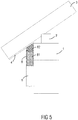
- FIG. 5 shows a part of a building, more precisely a part of a building wall wall formed by a wall 1 and a part of the roof of the building. From the roof are in the FIG. 1 a (roof) purlin 2, a (roof) rafter 3, and a eaves formwork 4 shown. The outside of the wall 1 is clad using a composite thermal insulation system. From the thermal insulation composite thermal insulation panels 5 and 8 are shown.
- the wall 1, the purlin 2, the rafters 3, the Traufschalung 4 and the thermal insulation board 5 correspond to those in the FIG. 7 with the reference numerals 101, 102, 103, 104 and 105 designated components. These components will therefore not be described again here; To avoid repetition will be on the on the FIG. 7 reference description referenced.
- the thermal insulation board 8 is in the FIGS. 2 and 3 shown thermal insulation device and replaced the conventional thermal insulation board 108 according to FIG. 7 ,
- the heat-insulating device 8 is not only as Pfettendämmung (see FIG. 1 ), but also as part of a thermal insulation composite system used.
- the achievable advantages are the same.
- the pivoting range of the second heat-insulating device part 82 is limited.
- the second heat-insulating member 82 can not be pivoted so far back because there is the wall 1 of the building.
- the second heat-insulating device part 82 at least a little backwards (to the wall 1) can be pivoted, and forward yes anyway.
- thermal insulation device Even with such a use of the heat-insulating element 8, if necessary, in the alternative FIG. 4 shown thermal insulation device are used.
- heat-insulating device parts 81, 82, 86 are made of good heat-insulating material, preferably of foamed plastic such as foamed polystyrene or of the product sold under the name Neopor.
- foamed plastic such as foamed polystyrene or of the product sold under the name Neopor.
- Neopor the product sold under the name
- the heat-insulating parts 81, 82, 86 are made of materials of different hardness or different compressibility.
- lighter and / or more compressible materials are used in the hard to reach areas of the building. That is, it could for example be provided make the second heat-insulating member 82 of softer material than the other heat-insulating members 81, 86.
- the heat-insulating device described above proves to be advantageous in many respects regardless of the details of the practical implementation. As a result, fewer blanks on the construction site and no longer any oblique blanks are required, and less waste is produced.
Landscapes
- Physics & Mathematics (AREA)
- Engineering & Computer Science (AREA)
- Architecture (AREA)
- Acoustics & Sound (AREA)
- Electromagnetism (AREA)
- Civil Engineering (AREA)
- Structural Engineering (AREA)
- Building Environments (AREA)
Abstract
Es wird eine Wärmedämmvorrichtung insbesondere zur Wärmedämmung von Gebäuden oder Gebäudeteilen beschrieben, wobei die Wärmedämmvorrichtung ein erstes Wärmedämmvorrichtungs-Teil und ein zweites Wärmedämmvorrichtungs-Teil enthält. Die beschriebene Wärmedämmvorrichtung zeichnet sich dadurch aus, dass die beiden Wärmedämmvorrichtungs-Teile so miteinander in Eingriff bringbar sind, dass sie im bestimmungsgemäß miteinander in Eingriff gebrachten Zustand relativ zueinander schwenkbar sind.
Description
- Die vorliegende Erfindung betrifft eine Wärmedämmvorrichtung gemäß dem Oberbegriff des Patentanspruchs 1.
- Wärmedämmvorrichtungen für Gebäude sind seit vielen Jahren in unzähligen Ausführungsformen bekannt. Zu den bekanntesten Wärmedämmvorrichtungen gehören die Wärmedämmplatten eines Wärmedämmverbundsystems. Unter Verwendung solcher Wärmedämmplatten lassen sich die Außenwände eines Gebäudes relativ schnell und einfach mit einer sehr wirksamen Wärmedämmung versehen. Allerdings weisen fast alle Gebäude diverse Gebäudeteile auf, deren Wärmedämmung einen unverhältnismäßig großen Aufwand erfordert. Hierzu zählt beispielsweise der an die Dachtraufe angrenzende Außenwandbereich eines Gebäudes mit seitlich überstehendem Schrägdach.
- Dieser Gebäudeteil ist in
Figur 7 dargestellt. DieFigur 7 zeigt einen Teil einer durch eine Mauer 101 gebildete Gebäudeaußenwand und einen Teil des Daches des Gebäudes. Vom Dach sind in derFigur 7 eine (Dach-)Pfette 102, ein (Dach-)Sparren 103, und eine im Dachtraufenbereich an der Unterseite der Dachsparren 103 vorgesehene Traufschalung 104 dargestellt. Die Pfette 102 ist eine Fußpfette, die mittig auf der Wand 101 (oder einem darüber angebrachten Ringanker) aufliegt und als Träger für die darauf aufliegenden Sparren 103 dient. Die Außenseite der Mauer 101 ist unter Verwendung eines Wärmedämmverbundsystems verkleidet. Vom Wärmedämmverbundsystem sind Wärmedämmplatten 105 und 106 dargestellt. Die untere Wärmedämmplatte 105 ist eine "normale" Wärmedämmplatte, die nur die richtige Länge und Breite aufweisen muss. Die obere Wärmedämmplatte 106 erstreckt sich bis zur schräg nach unten verlaufenden Traufschalung 104 nach oben und muss an ihrem oberen Ende eine Schräge 107 aufweisen, die der Neigung der Traufschalung 104 entspricht, so dass die Schräge 107 der Wärmedämmplatte 106 vollflächig mit der Traufschalung 204 in Kontakt kommt. Da die vorzusehende Schräge 107 von Gebäude zu Gebäude unterschiedlich sein kann, ist es in den meisten Fällen erforderlich, die Wärmedämmplatten 106 auf der Baustelle individuell zuzuschneiden. Dies ist erkennbar mit einem sehr großen Aufwand verbunden. Außerdem besteht auch bei noch so großer Sorgfalt ein erhebliches Risiko, dass die Wärmedämmplatten 106 dennoch nicht optimal in die auszufüllende Lücke passen. - Ähnliche Probleme treten bei der Herstellung einer auch als Pfettendämmung bezeichneten Wärmedämmvorrichtung auf. Eine solche Wärmedämmvorrichtung ist ebenfalls in der
Figur 7 gezeigt und dort mit dem Bezugszeichen 108 bezeichnet. Die Wärmedämmvorrichtung 108 dient zum Verschließen einer am Einbauort vorhandenen Öffnung im Gebäude. Die besagte Öffnung ist nach unten durch die Oberseite der Pfette 102, nach oben durch die auf der Oberseite der Sparren 103 angebrachte, in derFigur 7 nicht gezeigte Schalung, und zur Seite hin durch je zwei benachbarte Sparren 103 begrenzt. Die zum Verschließen einer solchen Öffnung verwendete Wärmedämmvorrichtung 108 kann auf der Mauer 101 aufliegen, genauer gesagt in dem sich an die Pfette 102 anschließenden äußeren Mauerabschnitt aufliegen und sich bis zur erwähnten Schalung nach oben erstrecken. Dieser Bereich wird bisher mit Mauerwerksbausteinen oder mit Wärmedämmplatten verschlossen. Auch hier muss am oberen Ende der Wärmedämmvorrichtung 108 eine an die Dachneigung angepasste Schräge 109 ausgebildet sein, die vollflächig an der an der Sparrenoberseite vorgesehenen Schalung anliegt. Hierbei treten folglich die selben Probleme und Risiken auf wie bei der Herstellung der Wärmedämmplatte 106. - Der vorliegenden Erfindung liegt daher die Aufgabe zugrunde, eine Möglichkeit zu finden, durch welche sich Wärmedämmvorrichtungen, die eine individuell an die herrschenden Verhältnisse angepasste Schräge aufweisen müssen oder sonstige arbeitsintensive Anpassungen erfordern, schnell und einfach herstellen lassen.
- Diese Aufgabe wird erfindungsgemäß durch die in Patentanspruch 1 beanspruchte Wärmedämmvorrichtung gelöst.
- Die erfindungsgemäße Wärmedämmvorrichtung zeichnet sich dadurch aus, dass sie ein erstes Wärmedämmvorrichtungs-Teil und ein zweites Wärmedämmvorrichtungs-Teil enthält, die so miteinander in Eingriff bringbar sind, dass sie im bestimmungsgemäß miteinander in Eingriff gebrachten Zustand relativ zueinander schwenkbar sind.
- Die erfindungsgemäße Wärmedämmvorrichtung ermöglicht es beispielsweise, das zweite Wärmedämmvorrichtungs-Teil durch ein entsprechendes Schwenken desselben wunschgemäß in Bezug zu dem Gebäudeteil auszurichten, mit welchem es in Kontakt kommen muss. Genauer gesagt kann allein durch ein entsprechendes Schwenken und insbesondere ohne einen individuellen Zuschnitt des zweiten Wärmedämmvorrichtungs-Teils erreicht werden, dass eine bestimmte Fläche des zweiten Wärmedämmvorrichtungs-Teils parallel zur zu der Fläche des Gebäudes ausgerichtet ist, mit welcher sie in Kontakt kommen muss.
- In einer vorteilhaften Weiterbildung der Erfindung ist zusätzlich ein drittes Wärmedämmvorrichtungs-Teil vorgesehen, das so mit dem ersten Wärmedämmvorrichtungs-Teil verbindbar ist, dass sich diese Wärmedämmvorrichtungs-Teile im bestimmungsgemäß miteinander verbundenen Zustand und ohne eine Lösung der Verbindung wunschgemäß weit ineinanderschieben und auseinanderziehen lassen.
- Dadurch lässt eine noch flexiblere Anpassung der Wärmedämmvorrichtung an die gegebenen Verhältnisse erzielen. Insbesondere kann das erste Wärmedämmvorrichtungs-Teil dadurch mit geringem Aufwand so positioniert werden, dass das zweite Wärmedämmvorrichtungs-Teil noch einfacher und genauer in seine bestimmungsgemäße Lage gebracht werden kann.
- Die erfindungsgemäße Wärmedämmvorrichtung lässt sich also sehr viel schneller und einfacher individuell an die herrschenden Verhältnisse anpassen als es bei herkömmlichen Wärmedämmvorrichtungen der Fall ist.
- Vorteilhafte Weiterbildungen der Erfindung sind den Unteransprüchen, der folgenden Beschreibung, und den Figuren entnehmbar.
- Die Erfindung wird nachfolgend anhand von Ausführungsbeispielen unter Bezugnahme auf die Figuren näher erläutert. Es zeigen
- Figur 1
- eine Seitenansicht eines Gebäudeteils, in welchem die im Folgenden näher beschriebene Wärmedämmvorrichtung als Pfettendämmung verwendet wird,
- Figuren 2 und 3
- größere Darstellungen der in der Anordnung gemäß
Figur 1 als Pfettendämmung zum Einsatz kommenden Wärmedämmvorrichtung, - Figur 4
- eine vorteilhafte Weiterbildung der in den
Figuren 2 und 3 gezeigten Wärmedämmvorrichtung, - Figur 5
- eine Seitenansicht eines Gebäudeteils, in welchem die im Folgenden näher beschriebene Wärmedämmvorrichtung als ein Teil eines Wärmedämmverbundsystems verwendet wird,
- Figur 6
- eine vergrößerte Darstellung eines Ausschnittes der in der
Figur 5 gezeigten Anordnung, und - Figur 7
- eine Seitenansicht eines Gebäudeteils, in welchem herkömmliche Wärmedämmvorrichtungen als Pfettendämmung und als ein ähnlich ausgebildeter Teil eines Wärmedämmverbundsystem zum Einsatz kommen.
- Die im Folgenden näher beschriebene Wärmedämmvorrichtung ist eine Wärmedämmvorrichtung insbesondere zur Wärmedämmung von Gebäuden oder Gebäudeteilen.
- Die beschriebene Wärmedämmvorrichtung kann für verschiedene Zwecke eingesetzt werden. Im Folgenden wird vor allem die Verwendung der Wärmedämmvorrichtung als Pfettendämmung und als ein ähnlich ausgebildeter Teil eines Wärmedämmverbundsystems näher beschrieben. Es sei jedoch bereits an dieser Stelle darauf hingewiesen, dass der Einsatz der hier vorgestellten Wärmedämmvorrichtung nicht hierauf beschränkt ist. Die Wärmedämmvorrichtung lässt sich auch für andere Zwecke an Gebäuden oder Gebäudeteilen einsetzen, und kann auch zur Wärmedämmung beliebiger anderer Gegenstände, also nicht nur zur Wärmedämmung von Gebäuden und Gebäudeteilen zum Einsatz kommen.
- In dem in der
Figur 1 gezeigten Gebäudeteil wird die hier vorgestellte Wärmedämmvorrichtung als Pfettendämmung eingesetzt. - Die
Figur 1 zeigt einen Teil einer durch eine Mauer 1 gebildeten Gebäudeaußenwand und einen Teil des Daches des Gebäudes. Vom Dach sind in derFigur 1 eine (Dach-)Pfette 2 und ein (Dach-)Sparren 3 gezeigt. Die Mauer 1, die Pfette 2 und der Sparren 3 entsprechen den in derFigur 7 mit den Bezugszeichen 101, 102, und 103 bezeichneten Komponenten. Diese Komponenten werden daher hier nicht nochmals beschrieben; zur Vermeidung von Wiederholungen wird auf die auf dieFigur 7 bezugnehmende Beschreibung verwiesen. Ferner zeigt dieFigur 1 die durch die hier vorgestellte Wärmedämmvorrichtung realisierte Pfettendämmung. Die als Pfettendämmung verwendete Wärmedämmvorrichtung ist in derFigur 1 mit dem Bezugszeichen 8 bezeichnet. Die Wärmedämmvorrichtung 8 ist an der selben Stelle eingebaut, verschließt die selbe Öffnung im Gebäude, und hat die selbe Funktion wie die in derFigur 7 gezeigte und unter Bezugnahme darauf beschriebene Pfettendämmung 108. Allerdings unterscheidet sich der Aufbau der Wärmedämmvorrichtung 8 sehr deutlich von der herkömmlichen Pfettendämmung 108. - Der Aufbau der hier vorgestellten Wärmedämmvorrichtung 8 ist insbesondere in den
Figuren 2 und 3 gut erkennbar. - Die Wärmedämmvorrichtung 8 enthält mehreren Einzelteile, genauer gesagt ein erstes Wärmedämmvorrichtungs-Teil 81 und ein zweites Wärmedämmvorrichtungs-Teil 82. Diese Wärmedämmvorrichtungs-Teile 81, 82 sind so zusammensetzbar bzw. so miteinander in Eingriff bringbar, dass sie im bestimmungsgemäß miteinander in Eingriff gebrachten Zustand relativ zueinander schwenkbar sind.
- Dies ist in den
Figuren 2 und 3 veranschaulicht. DieFiguren 2 und 3 zeigen die Wärmedämmvorrichtungs-Teile 81, 82 im bestimmungsgemäß miteinander in Eingriff gebrachten Zustand. Dabei ist es so, dass das erste Wärmedämmvorrichtungs-Teil 81 an seiner dem zweiten Wärmedämmvorrichtungs-Teil 82 zugewandten Seite eine Vertiefung 811 aufweist, und das zweite Wärmedämmvorrichtungs-Teil 82 an seiner dem ersten Wärmedämmvorrichtungs-Teil 81 zugewandten Seite eine komplementär zur Vertiefung 811 ausgebildete Erhebung 821 aufweist. Vertiefung und Erhebung können auch vertauscht sein, sodass also das zweite Wärmedämmvorrichtungs-Teil 82 an seiner dem ersten Wärmedämmvorrichtungs-Teil 81 zugewandten Seite eine Vertiefung aufweisen kann, und das erste Wärmedämmvorrichtungs-Teil an seiner dem zweiten Wärmedämmvorrichtungs-Teil zugewandten Seite eine komplementär zur Vertiefung ausgebildete Erhebung aufweisen kann. - Das erste Wärmedämmvorrichtungs-Teil 81 und das zweite Wärmedämmvorrichtungs-Teil 82 werden dadurch miteinander in Eingriff gebracht, dass die Erhebung 821 in die Vertiefung 811 eingesetzt wird.
- Die Vertiefung 811 und die Erhebung 821 sind so ausgebildet, dass die Wärmedämmvorrichtungs-Teile 81, 82 um eine vorbestimmte virtuelle Schwenkachse 83, und zwar vorzugsweise nur um diese Schwenkachse 83 relativ zueinander schwenkbar sind.
- Die
Figuren 2 und 3 zeigen zwei unterschiedliche Schwenkstellungen der Wärmedämmvorrichtungs-Teile 81, 82. Bei der in derFigur 3 gezeigten Wärmedämmvorrichtung fluchten die Wärmedämmvorrichtungs-Teile 81, 82, sind also nicht relativ zueinander geschwenkt. Die selbe Relativlage weisen die Wärmedämmvorrichtungs-Teile 81, 82 der in derFigur 1 gezeigten Pfettendämmung 8 auf. Diese Relativlage bzw. dieser Schwenkwinkel zwischen den Wärmedämmvorrichtungs-Teilen 81, 82 wurde bei der in derFigur 1 gezeigten Anordnung gewählt, weil in diesem Zustand eine Fläche 84 des zweiten Wärmedämmvorrichtungs-Teils 82 vollflächig an der Dachkomponente anliegt, bis zu welcher sie sich erstrecken soll. Bei der besagten Fläche des zweiten Wärmedämmvorrichtungs-Teils 82 handelt es sich um eine Schräge 84, die am vorderen Ende, das heißt an dem vom ersten Wärmedämmvorrichtungs-Teil 81 abgewandten Ende des zweiten Wärmedämmvorrichtungs-Teils 82 vorgesehen ist. - Wiese die Dachkomponente, bis zu welcher sich das zweite Wärmedämmvorrichtungs-Teil 82 erstrecken soll, eine andere Neigung oder Schräge auf, dann könnte allein durch eine andere Schwenkstellung des zweiten Wärmedämmvorrichtungs-Teils 82 in Bezug zum ersten Wärmedämmvorrichtungs-Teil 81 erreicht werden, dass auch in einem solchen Fall die Schräge 84 des zweiten Wärmedämmvorrichtungs-Teils 82 vollflächig an der besagten Dachkomponente anliegt.
- Bei der in der
Figur 2 gezeigten Relativlage der Wärmedämmvorrichtungs-Teile 81, 82 ist das zweite Wärmedämmvorrichtungs-Teil 82 ein Stück nach rechts (bezogen auf die in derFigur 1 gezeigte Einbaulage weiter zum Gebäude hin) geschwenkt. Dadurch steht die Schräge 84 weniger steil und könnte mit einem entsprechend flacheren Dach vollflächig in Kontakt kommen. - Bei einem in den Figuren nicht gezeigten Schwenken das zweiten Wärmedämmvorrichtungs-Teils 82 nach links (bezogen auf die in der
Figur 1 gezeigte Einbaulage vom Gebäude weg) würde die Schräge 84 steiler stehen und könnte mit einem entsprechend steileren Dach vollflächig in Kontakt kommen. - Durch ein geeignetes Schwenken das zweiten Wärmedämmvorrichtungs-Teils 82 in Bezug zum ersten Wärmedämmvorrichtungs-Teil 81 kann das zweiten Wärmedämmvorrichtungs-Teil 82 also in eine solche Lage gebracht werden, dass eine bestimmte Fläche desselben parallel zu dem Gebäudeteil ausgerichtet ist, bis zu welchem es sich erstrecken soll, und in dieser Ausrichtung kann die besagte Fläche das zweiten Wärmedämmvorrichtungs-Teils 82 mit dem betreffenden Gebäudeteil vollflächig anliegend in Kontakt kommen. Dies kann allein durch ein entsprechendes Schwenken des zweiten Wärmedämmvorrichtungs-Teils 82 erreicht werden. Eine zusätzliche Bearbeitung des weiten Wärmedämmvorrichtungs-Teils 82, beispielsweise ein individuelles Zuschneiden desselben kann entfallen.
- Ein Zuschneiden des zweiten Wärmedämmvorrichtungs-Teils 82 oder sonstige Anpassungen können sich unter bestimmten Umständen dennoch als vorteilhaft erweisen. Die erwähnte Schwenkbarkeit der Wärmedämmvorrichtungs-Teile 81, 82 macht nämlich Nachjustierungen möglich, sodass das Zuschneiden oder die sonstigen Bearbeitungen keine hohe Präzision erfordern, also schnell und einfach erfolgen können.
- Bei der Fläche des zweiten Wärmedämmvorrichtungs-Teils 82, die vorzugsweise vollflächig mit dem Gebäudeteil in Kontakt kommen soll, bis zu welchem sich das zweite Wärmedämmvorrichtungs-Teil 82 erstrecken soll, ist im betrachteten Beispiel die bereits erwähnte Schräge 84. Prinzipiell könnte es sich aber auch um eine beliebige andere Fläche des zweiten Wärmedämmvorrichtungs-Teils 82 handeln.
- In dieser Fläche, im betrachteten Beispiel also in der Schräge 84 ist eine Aussparung 85 vorgesehen, welche sich über die gesamte Länge der Schräge 84 erstreckt. Die Aussparung 85 ist zur Aufnahme eine Kompribandes ausgelegt, welches dafür sorgt, dass gegebenenfalls vorhandene Undichtigkeiten zwischen der Schräge 84 und dem Gebäudeteil, mit welchem die Schräge 84 in Kontakt kommen soll, luftdicht verschlossen werden.
- Im betrachteten Beispiel weist die Vertiefung 811 keine Hinterschneidung auf, sodass im miteinander in Eingriff gebrachten Zustand der Wärmedämmvorrichtungs-Teile 81, 82 das zweite Wärmedämmvorrichtungs-Teile 82, genauer gesagt dessen Erhebung 821 nur lose in der Vertiefung 811 liegt und auch nicht anderweitig am ersten Wärmedämmvorrichtungs-Teil 81 gehalten wird. Bei Bedarf kann jedoch auch eine Verbindung zwischen den Wärmedämmvorrichtungs-Teilen 81, 82 vorgesehen werden.
- Die Vertiefung 811 verläuft parallel zur virtuellen Schwenkachse 83 und erstreckt sich über die gesamte Seite des Wärmedämmvorrichtungs-Teils auf welcher sie vorgesehen ist. Entsprechendes gilt für die zugeordnete Erhebung 821. Auch diese verläuft parallel zur virtuellen Schwenkachse 83 und erstreckt sich über die gesamte Seite des Wärmedämmvorrichtungs-Teils auf welcher sie vorgesehen ist.
- Die Vertiefung 811 hat im betrachteten Beispiel einen kreissegmentförmigen Querschnitt. Die Erhebung 821 weist einen entsprechenden komplementären Querschnitt auf.
- Die miteinander in Eingriff zu bringenden Komponenten der Wärmedämmvorrichtungs-Teile 81, 82 können prinzipiell auch auf beliebige andere Art und Weise ausgebildet sein und/oder auf beliebige andere Art und Weise miteinander in Eingriff gebracht werden.
- Unabhängig davon, wie die miteinander in Eingriff zu bringenden Komponenten der beiden Wärmedämmvorrichtungs-Teile 81, 82 ausgebildet sind und in Eingriff gebracht werden, ist es vorzugsweise so, dass im bestimmungsgemäß miteinander in Eingriff gebrachten Zustand der Wärmedämmvorrichtungs-Teile 81, 82 unabhängig von deren Relativlage kein Luftspalt zwischen den beiden Wärmedämmvorrichtungs-Teilen 81, 82 vorhanden ist und mithin keine Luft zwischen den beiden Wärmedämmvorrichtungs-Teile 81, 82 hindurchtreten kann.
- Es kann sich als vorteilhaft erweisen, wenn, wie beispielsweise aus
Figur 3 ersichtlich ist, das zweite Wärmedämmvorrichtungs-Teil 82 weniger dick ausgebildet ist als das erste Wärmedämmvorrichtungs-Teil 81. Dann können bei bestimmten Einbauverhältnissen größere Schwenkbewegungen durchgeführt werden (siehe beispielsweiseFigur 6 ). - Das erste Wärmedämmvorrichtungs-Teil 81 wird im betrachteten Beispiel durch eine Platte gebildet. Hierbei kann es sich im Wesentlichen um eine ganz normale Wärmedämmplatte handeln, wie sie auch bei den bekannten Wärmedämmverbundsystemen zum Einsatz kommt. Die einzige Besonderheit besteht darin, dass sie sich wie beschrieben mit dem zweiten Wärmedämmvorrichtungs-Teil 82 in Eingriff bringen lassen muss.
- Das zweite Wärmedämmvorrichtungs-Teil 82 kann ebenfalls durch eine entsprechend zugeschnittene Platte gebildet werden. Auch hierbei kann es sich im Wesentlichen um eine ganz normale Wärmedämmplatte handeln, wie sie auch bei den bekannten Wärmedämmverbundsystemen zum Einsatz kommt. Die Besonderheit besteht darin, dass sie sich wie beschrieben mit dem ersten Wärmedämmvorrichtungs-Teil 81 in Eingriff bringen lassen muss und eventuell die erwähnte Schräge 84 aufweist. Je nach Ausbildung der Schräge 84 kann das zweite Wärmedämmvorrichtungs-Teil 82 die Form eines schwenkbaren Keils annehmen.
- Das erste Wärmedämmvorrichtungs-Teil 81 ist dazu ausgelegt, am Gebäude befestigt zu werden. Das zweite Wärmedämmvorrichtungs-Teil 82 kann ebenfalls dazu ausgelegt sein, am Gebäude befestigt zu werden. Es kann aber auch vorgesehen werden, die Wärmedämmvorrichtungs-Teile 81, 82 so am Gebäude zu montieren, dass das zweite Wärmedämmvorrichtungs-Teil 82 zwischen dem ersten Wärmedämmvorrichtungs-Teil 81 und dem Gebäude eingeklemmt und durch diese Klemmverbindung in seiner bestimmungsgemäßen Position und Lage gehalten wird.
- Vorzugsweise ist die außen am Gebäude zu liegen kommende Seite des ersten Wärmedämmvorrichtungs-Teils 81 mit diversen Erhebungen und/oder Vertiefungen strukturiert und mit einem Putzhaftgrund versehen. Dies verbessert die Haftung einer auf dieser Seite aufgebrachten Putzschicht.
- Auf der um montierten Zustand unten zu liegen kommenden Unterseite des ersten Wärmedämmvorrichtungs-Teils 81 sind vorzugsweise Nuten oder sonstige Erhebungen oder Vertiefungen zur besseren Haftung im Mörtelbett bzw. im Klebeschaum vorgesehen.
- Eine vorteilhafte Weiterbildung der vorstehend beschriebenen Wärmedämmvorrichtung 8 ist in
Figur 4 gezeigt. Die darin gezeigte Wärmedämmvorrichtung enthält neben den vorstehend bereits beschriebenen Wärmedämmvorrichtungs-Teilen 81, 82 zusätzlich ein drittes Wärmedämmvorrichtungs-Teil 86, das dazu ausgelegt ist, mit dem ersten Wärmedämmvorrichtungs-Teil 81 verbunden zu werden. Genauer gesagt sind das erste Wärmedämmvorrichtungs-Teil 81 und das dritte Wärmedämmvorrichtungs-Teil 86 so miteinander verbindbar, dass im bestimmungsgemäß miteinander verbundenen Zustand das erste Wärmedämmvorrichtungs-Teil 81 und das dritte Wärmedämmvorrichtungs-Teil 86 ohne eine Lösung der Verbindung relativ zueinander verschiebbar sind. - Das erste Wärmedämmvorrichtungs-Teil 81 weist an seiner dem dritten Wärmedämmvorrichtungs-Teil 86 zugewandten Seite Verbindungsmittel zur Verbindung des ersten Wärmedämmvorrichtungs-Teils 81 mit dem dritten Wärmedämmvorrichtungs-Teil 86 auf, und das dritte Wärmedämmvorrichtungs-Teil 86 weist an seiner dem ersten Wärmedämmvorrichtungs-Teil 81 zugewandten Seite komplementär ausgebildete Verbindungsmittel auf.
- Dabei ist die dem dritten Wärmedämmvorrichtungs-Teil 86 zugewandte Seite des ersten Wärmedämmvorrichtungs-Teils 81 die vom zweiten Wärmedämmvorrichtungs-Teil 82 abgewandte Seite des ersten Wärmedämmvorrichtungs-Teils 81.
- Die zur Verbindung von erstem und drittem Wärmedämmvorrichtungs-Teil 81, 86 vorgesehenen Verbindungsmittel sind zur Herstellung einer Nut- und Feder-Verbindung ausgelegte Verbindungsmittel. Genauer gesagt ist es im betrachteten Beispiel so, dass im ersten Wärmedämmvorrichtungs-Teil 81 eine Vertiefung (Nut) vorgesehen ist, und im dritten Wärmedämmvorrichtungs-Teil 86 eine komplementär ausgebildete Erhebung (Feder) vorgesehen ist. Die Anordnung von Nut und Feder können selbstverständlich auch vertauscht werden.
- Das erste und das dritte Wärmedämmvorrichtungs-Teil 81, 86, insbesondere deren zur gegenseitigen Verbindung vorgesehenen Verbindungsmittel sind so ausgebildet, dass sich das erste Wärmedämmvorrichtungs-Teil 81 und das dritte Wärmedämmvorrichtungs-Teil 86 stufenlos wunschgemäß weit zusammenschieben und auseinanderziehen lassen.
- In der
Figur 4 ist ein Zustand gezeigt, in welchem das erste Wärmedämmvorrichtungs-Teil 81 und das dritte Wärmedämmvorrichtungs-Teil 86 relativ weit auseinandergezogen sind. Die beiden Teile könnten sogar noch ein Stück weiter auseinandergezogen werden. Sie könnten aber auch weiter zusammengeschoben werden. Durch eine solche stufenlose Verschiebbarkeit lässt sich auf sehr einfache Art und Weise die Höhe der Wärmedämmvorrichtung variieren bzw. wunschgemäß an die gegebenen Verhältnisse anpassen. - Bei Bedarf kann anstelle der in den
Figuren 2 und 3 gezeigten Wärmedämmvorrichtung die in derFigur 4 gezeigte Wärmedämmvorrichtung verwendet werden. Dies erfordert keine besonderen Vorkehrungen und ist problemlos durchführbar. Das heißt, auch die in derFigur 4 gezeigte, noch flexibler einsetzbare Wärmedämmvorrichtung kann als Pfettendämmung verwendet werden. - Das dritte Wärmedämmvorrichtungs-Teil 86 wird im betrachteten Beispiel durch eine Platte gebildet. Hierbei kann es sich im Wesentlichen um eine ganz normale Wärmedämmplatte handeln, wie sie auch bei den bekannten Wärmedämmverbundsystemen zum Einsatz kommt. Die einzige Besonderheit besteht darin, dass sie sich wie beschrieben mit dem ersten Wärmedämmvorrichtungs-Teil 81 verbinden lassen muss.
- Vorzugsweise ist die außen am Gebäude zu liegen kommende Seite des dritten Wärmedämmvorrichtungs-Teils 86 mit diversen Erhebungen und/oder Vertiefungen strukturiert und mit einem Putzhaftgrund versehen. Dies verbessert die Haftung einer auf dieser Seite aufgebrachten Putzschicht.
- Auf der im montierten Zustand unten zu liegen kommenden Unterseite des dritten Wärmedämmvorrichtungs-Teils 81 sind vorzugsweise Nuten oder sonstige Erhebungen oder Vertiefungen zur besseren Haftung im Mörtelbett bzw. im Klebeschaum vorgesehen.
- Es dürfte einleuchten und bedarf keiner näheren Erläuterung, dass auch die Kombination von erstem Wärmedämmvorrichtungs-Teil 81 und drittem Wärmedämmvorrichtungs-Teil 86 allein, das heißt ohne Vorsehen des zweiten Wärmedämmvorrichtungs-Teils 82 vorteilhaft ist. Auf diese Art und Weise könnte eine normale Wärmedämmplatte mit stufenlos variierbarer Höhe und/oder stufenlos variierbarer Breite geschaffen werden. Auch hierdurch können zumindest in bestimmten Fällen individuelle Zuschnitte der Wärmedämmplatten zur Anpassung an die gegebenen Verhältnisse vermieden werden.
- Bei nicht vorhandenem zweitem Wärmedämmvorrichtungs-Teil 82 muss die Oberseite des ersten Wärmedämmvorrichtungs-Teils 81 natürlich keine Vertiefung 811 für das zweite Wärmedämmvorrichtungs-Teil 82 aufweisen, sondern kann an dieser Stelle wie eine "normale" Wärmedämmplatte ausgebildet sein.
- Eine weitere Einsatzmöglichkeit für die beschriebene Wärmedämmvorrichtung gemäß den
Figuren 2 und 3 ist inFigur 5 veranschaulicht. DieFigur 5 zeigt einen Teil eines Gebäudes, genauer gesagt einen Teil einer durch eine Mauer 1 gebildeten Gebäudeaußenwand und einen Teil des Daches des Gebäudes. Vom Dach sind in derFigur 1 eine (Dach-)Pfette 2, ein (Dach-)Sparren 3, und eine Traufschalung 4 gezeigt. Die Außenseite der Mauer 1 ist unter Verwendung eines Wärmedämmverbundsystems verkleidet. Vom Wärmedämmverbundsystem sind Wärmedämmplatten 5 und 8 dargestellt. - Die Mauer 1, die Pfette 2, der Sparren 3, die Traufschalung 4 und die Wärmedämmplatte 5 entsprechen den in der
Figur 7 mit den Bezugszeichen 101, 102, 103, 104 und 105 bezeichneten Komponenten. Diese Komponenten werden daher hier nicht nochmals beschrieben; zur Vermeidung von Wiederholungen wird auf die auf dieFigur 7 bezugnehmende Beschreibung verwiesen. - Die Wärmedämmplatte 8 ist die in den
Figuren 2 und 3 gezeigte Wärmedämmvorrichtung und ersetzt die herkömmliche Wärmedämmplatte 108 gemäßFigur 7 . - Das heißt, die Wärmedämmvorrichtung 8 ist nicht nur als Pfettendämmung (siehe
Figur 1 ), sondern auch als Teil eines Wärmedämmverbundsystems einsetzbar. Die erzielbaren Vorteile sind die selben. Bei der in derFigur 5 gezeigten Einsatzmöglichkeit für die Wärmedämmvorrichtung 8 ist der Schwenkbereich des zweiten Wärmedämmvorrichtungs-Teil 82 beschränkt. Insbesondere kann das zweite Wärmedämmvorrichtungs-Teil 82 nicht so weit nach hinten geschwenkt werden, weil sich dort die Wand 1 des Gebäudes befindet. Wie insbesondere ausFigur 6 ersichtlich ist, kann das das zweite Wärmedämmvorrichtungs-Teil 82 zumindest ein wenig nach hinten (zur Mauer 1) geschwenkt werden, und nach vorne ja sowieso. - Auch bei einer solchen Verwendung des Wärmedämmelements 8 kann bei Bedarf alternativ die in der
Figur 4 gezeigte Wärmedämmvorrichtung zum Einsatz kommen. - Der Vollständigkeit halber sei abschließend erwähnt, dass alle Wärmedämmvorrichtungs-Teile 81, 82, 86 aus gut wärmedämmendem Material, vorzugsweise aus geschäumtem Kunststoff wie beispielsweise geschäumtem Polystyrol oder aus dem unter dem Namen Neopor verkauften Produkt hergestellt sind. Selbstverständlich kommen auch alle anderen Materialien in Frage, die zur Herstellung von Wärmedämmplatten oder dergleichen verwendet werden oder verwendbar sind.
- Es kann sich als vorteilhaft erweisen, wenn die Wärmedämmvorrichtungs-Teile 81, 82, 86 aus Materialen mit unterschiedlicher Härte bzw. unterschiedlicher Komprimierbarkeit hergestellt werden. dabei könnte insbesondere vorgesehen werden, dass in den schwer zugänglichen Stellen des Gebäudes leichter und/oder stärker komprimierbare Materialien zum Einsatz kommen. Das heißt, es könnte beispielsweise vorgesehen werden, das zweite Wärmedämmvorrichtungs-Teil 82 aus weicherem Material herzustellen als die anderen Wärmedämmvorrichtungs-Teile 81, 86.
- Die vorstehend beschriebene Wärmedämmvorrichtung erweist sich unabhängig von den Einzelheiten der praktischen Realisierung in vielfacher Hinsicht als vorteilhaft. Dadurch sind auf der Baustelle generell weniger Zuschnitte und überhaupt keine Schräg-Zuschnitte mehr erforderlich, und es entsteht zudem weniger Abfall.
-
- 1
- Mauer
- 2
- (Dach-)Pfette
- 3
- (Dach-)Sparren
- 4
- Traufschalung
- 5
- Dämmplatte
- 8
- als Pfettendämmung verwendete Wärmedämmvorrichtung
- 81
- erstes Wärmedämmvorrichtungs-Teil
- 82
- zweites Wärmedämmvorrichtungs-Teil
- 83
- virtuelle Schwenkachse
- 84
- Schräge an 82
- 85
- Aussprung in 84
- 86
- drittes Wärmedämmvorrichtungs-Teil
- 811
- Vertiefung in 81
- 821
- Erhebung an 82
- 101
- Mauer
- 102
- (Dach-)Pfette
- 103
- (Dach-)Sparren
- 104
- Traufschalung
- 105
- Wärmedämmplatte
- 106
- Wärmedämmplatte
- 107
- Schräge an 106
- 108
- Pfettendämmung
- 109
- Schräge an 108
Claims (15)
- Wärmedämmvorrichtung insbesondere zur Wärmedämmung von Gebäuden oder Gebäudeteilen, wobei die Wärmedämmvorrichtung ein erstes Wärmedämmvorrichtungs-Teil (81) und ein zweites Wärmedämmvorrichtungs-Teil (82) enthält, dadurch gekennzeichnet, dass die beiden Wärmedämmvorrichtungs-Teile so miteinander in Eingriff bringbar sind, dass sie im bestimmungsgemäß miteinander in Eingriff gebrachten Zustand relativ zueinander schwenkbar sind.
- Wärmedämmvorrichtung nach Anspruch 1, dadurch gekennzeichnet, dass die beiden Wärmedämmvorrichtungs-Teile (81, 82) so ausgebildet sind, dass im bestimmungsgemäß miteinander in Eingriff gebrachten Zustand derselben unabhängig von deren Relativlage kein Luftspalt zwischen den beiden Wärmedämmvorrichtungs-Teilen vorhanden ist.
- Wärmedämmvorrichtung nach einem der vorhergehenden Ansprüche, dadurch gekennzeichnet, dass von den Wärmedämmvorrichtungs-Teilen (81, 82) zumindest das erste Wärmedämmvorrichtungs-Teil (81) durch eine Wärmedämmplatte gebildet wird.
- Wärmedämmvorrichtung nach einem der vorhergehenden Ansprüche, dadurch gekennzeichnet, dass wenigstens eines der Wärmedämmvorrichtungs-Teile (81, 82) dazu ausgelegt ist, am Gebäude befestigt zu werden.
- Wärmedämmvorrichtung nach einem der vorhergehenden Ansprüche, dadurch gekennzeichnet, dass, bezogen auf den Zustand, in welchem die Wärmedämmvorrichtungs-Teile (81, 82) bestimmungsgemäß miteinander in Eingriff stehen,- das eine der Wärmedämmvorrichtungs-Teile (81, 82) an seiner dem anderen Wärmedämmvorrichtungs-Teil zugewandten Seite eine Vertiefung (811) aufweist, und- das andere Wärmedämmvorrichtungs-Teil an seiner dem einen Wärmedämmvorrichtungs-Teil zugewandten Seite eine komplementär zur Vertiefung ausgebildete Erhebung (821) aufweist.
- Wärmedämmvorrichtung nach Anspruch 5, dadurch gekennzeichnet, dass sich die Vertiefung (811) und die Erhebung (821) parallel zu einer virtuellen Schwenkachse (83) erstrecken, um welche die Wärmedämmvorrichtungs-Teile (81, 82) relativ zueinander schwenkbar sind.
- Wärmedämmvorrichtung nach Anspruch 5 oder 6, dadurch gekennzeichnet, dass die Vertiefung (811) einen kreissegmentförmigen Querschnitt hat.
- Wärmedämmvorrichtung nach einem der vorhergehenden Ansprüche, dadurch gekennzeichnet, dass das zweite Wärmedämmvorrichtungs-Teil (82) durch einen Keil gebildet wird.
- Wärmedämmvorrichtung nach einem der vorhergehenden Ansprüche, dadurch gekennzeichnet, dass das zweite Wärmedämmvorrichtungs-Teil (82) dazu ausgelegt ist, im bestimmungsgemäß am Gebäude montierten Zustand der Wärmedämmvorrichtung zwischen dem ersten Wärmedämmvorrichtungs-Teil (81) und dem Gebäude eingeklemmt zu werden und durch diese Klemmverbindung in seiner Position und Lage gehalten zu werden.
- Wärmedämmvorrichtung nach einem der vorhergehenden Ansprüche, dadurch gekennzeichnet, dass das zweite Wärmedämmvorrichtungs-Teil (82) dazu ausgelegt ist, mit einer an diesem ausgebildeten Fläche (84) vollflächig mit einer am Gebäude vorhandenen Schräge in Kontakt zu kommen.
- Wärmedämmvorrichtung nach Anspruch 10, dadurch gekennzeichnet, dass in der mit der Gebäudeschräge vollflächig in Kontakt zu bringenden Fläche (84) des zweiten Wärmedämmvorrichtungs-Teils (82) eine Aussparung (85) zum Einlegen eines Kompribandes ausgebildet ist.
- Wärmedämmvorrichtung nach Anspruch 10 oder 11, dadurch gekennzeichnet, dass die mit der Gebäudeschräge vollflächig in Kontakt zu bringende Fläche (84) des zweiten Wärmedämmvorrichtungs-Teils (82) durch eine Schräge gebildet wird, die an demjenigen Ende des zweiten Wärmedämmvorrichtungs-Teils (82) vorgesehen ist, welches im bestimmungsgemäß miteinander in Eingriff gebrachten Zustand der Wärmedämmvorrichtungs-Teile vom ersten Wärmedämmvorrichtungs-Teil (81) abgewandt ist.
- Wärmedämmvorrichtung nach einem der vorhergehenden Ansprüche, dadurch gekennzeichnet, dass das zweite Wärmedämmvorrichtungs-Teil (82) eine geringere Dicke aufweist als das erste Wärmedämmvorrichtungs-Teil.
- Wärmedämmvorrichtung nach einem der vorhergehenden Ansprüche, dadurch gekennzeichnet, dass die Wärmedämmvorrichtung ferner ein mit dem ersten Wärmedämmvorrichtungs-Teil (81) verbindbares drittes Wärmedämmvorrichtungs-Teil (86) umfasst, und dass im bestimmungsgemäß miteinander verbundenen Zustand des ersten und des dritten Wärmedämmvorrichtungs-Teils die verbundenen Wärmedämmvorrichtungs-Teile ohne eine Lösung der Verbindung wunschgemäß weit zusammenschiebbar und auseinanderziehbar sind.
- Wärmedämmvorrichtung nach Anspruch 14, dadurch gekennzeichnet, dass die dem dritten Wärmedämmvorrichtungs-Teil (86) zugewandte Seite des ersten Wärmedämmvorrichtungs-Teils (81) die vom zweiten Wärmedämmvorrichtungs-Teil (82) abgewandte Seite des ersten Wärmedämmvorrichtungs-Teils ist.
Applications Claiming Priority (1)
| Application Number | Priority Date | Filing Date | Title |
|---|---|---|---|
| DE102017100462.9A DE102017100462A1 (de) | 2017-01-11 | 2017-01-11 | Wärmedämmvorrichtung insbesondere zur Wärmedämmung von Gebäuden oder Gebäudeteilen |
Publications (1)
| Publication Number | Publication Date |
|---|---|
| EP3348726A1 true EP3348726A1 (de) | 2018-07-18 |
Family
ID=60954888
Family Applications (1)
| Application Number | Title | Priority Date | Filing Date |
|---|---|---|---|
| EP18150948.0A Withdrawn EP3348726A1 (de) | 2017-01-11 | 2018-01-10 | Wärmedämmvorrichtung insbesondere zur wärmedämmung von gebäuden oder gebäudeteilen |
Country Status (2)
| Country | Link |
|---|---|
| EP (1) | EP3348726A1 (de) |
| DE (1) | DE102017100462A1 (de) |
Citations (4)
| Publication number | Priority date | Publication date | Assignee | Title |
|---|---|---|---|---|
| US1708464A (en) * | 1926-07-28 | 1929-04-09 | Bodman Walter Light | Heat-insulating block |
| US6279293B1 (en) * | 1997-12-05 | 2001-08-28 | Leo V. Ojala | Insulated roof panel |
| DE10132766A1 (de) * | 2001-07-10 | 2003-01-30 | Bernd Beck | Einrichtung zur nachträglichen Wärmeisolierung von Hohlräumen |
| DE10216994A1 (de) * | 2002-04-16 | 2003-11-13 | Helmut Eid | Dämmplatte |
Family Cites Families (2)
| Publication number | Priority date | Publication date | Assignee | Title |
|---|---|---|---|---|
| DE3025394A1 (de) * | 1980-07-04 | 1982-04-29 | Karl Münch KG Verpackungstechnik, 6121 Hesseneck | Waermedaemmplatte |
| JP2013234505A (ja) * | 2012-05-10 | 2013-11-21 | Sakae Daikin Co Ltd | 断熱パネルの接合方法、それに用いる接着テープ及び断熱パネル |
-
2017
- 2017-01-11 DE DE102017100462.9A patent/DE102017100462A1/de active Pending
-
2018
- 2018-01-10 EP EP18150948.0A patent/EP3348726A1/de not_active Withdrawn
Patent Citations (4)
| Publication number | Priority date | Publication date | Assignee | Title |
|---|---|---|---|---|
| US1708464A (en) * | 1926-07-28 | 1929-04-09 | Bodman Walter Light | Heat-insulating block |
| US6279293B1 (en) * | 1997-12-05 | 2001-08-28 | Leo V. Ojala | Insulated roof panel |
| DE10132766A1 (de) * | 2001-07-10 | 2003-01-30 | Bernd Beck | Einrichtung zur nachträglichen Wärmeisolierung von Hohlräumen |
| DE10216994A1 (de) * | 2002-04-16 | 2003-11-13 | Helmut Eid | Dämmplatte |
Also Published As
| Publication number | Publication date |
|---|---|
| DE102017100462A1 (de) | 2018-07-12 |
Similar Documents
| Publication | Publication Date | Title |
|---|---|---|
| DE4242530C2 (de) | Bauelement für Wände, Decken oder Dächer von Bauwerken | |
| WO2018011329A1 (de) | Verbindungssystem | |
| DE2018497A1 (de) | System aus vereinigten Platten zur Bildung von Oberlichtern | |
| DE202013001849U1 (de) | Holzbauelement | |
| EP1857606A2 (de) | Putzleiste zur Anbringung am unteren Ende einer Gebäude-Wärmedämmung | |
| DE102009033038A1 (de) | Einbauleuchte | |
| EP2184421A2 (de) | Befestigungselement für ein Verlegesystem zu Erstellung eines Wand-, Boden- oder Deckenbelags sowie ein solches Verlegesystem | |
| EP3805480B1 (de) | Anputzdichtleiste | |
| DE3815140A1 (de) | Fugenschalung fuer glasbauelemente, welche aus mehreren glaselementen, insbesondere glasbausteinen bestehen | |
| EP1882788A2 (de) | Baustein für ein Modulbausystem, insbesondere zur Herstellung von fliegenden Bauten | |
| DE202017100115U1 (de) | Wärmedämmvorrichtung insbesondere zur Wärmedämmung von Gebäuden oder Gebäudeteilen | |
| EP2960392B1 (de) | Deckenrandschalungselement | |
| EP2591181A2 (de) | Lochplatten auf basis von gips sowie verfahren zum verlegen derselben | |
| WO2010075839A1 (de) | Fussbodenbelag | |
| DE202021104820U1 (de) | Befestigungsvorrichtung zur Befestigung eines einen Teil eines Daches eines Gebäudes bildenden Photovoltaikmoduls am Gebäude und Verbindungsvorrichtungen zur Verbindung solcher Photovoltaikmodule miteinander | |
| EP0617182B1 (de) | Mehrzweckleiste aus Kunststoff | |
| EP3348726A1 (de) | Wärmedämmvorrichtung insbesondere zur wärmedämmung von gebäuden oder gebäudeteilen | |
| EP2402522A2 (de) | Bau- und/oder Wärmedämmplatte sowie Wärmedämmverbundsystem mit entsprechender Platte | |
| EP0607788A2 (de) | Dehnungsfugenstreifen | |
| DE102015110129A1 (de) | Sichtbeton-Schalung | |
| DE202010001874U1 (de) | Montageplatte | |
| EP3372749A2 (de) | Bodendielensystem | |
| EP2447441B1 (de) | Befestigungsvorrichtung für Fassenverkleidungselemente | |
| WO2010075855A1 (de) | Dornsystem für den betonbau | |
| EP3431682B1 (de) | Dehnungsprofil zur aufnahme einer horizontalen spannung umfassend verankerungsflügel und einen zentralbereich |
Legal Events
| Date | Code | Title | Description |
|---|---|---|---|
| PUAI | Public reference made under article 153(3) epc to a published international application that has entered the european phase |
Free format text: ORIGINAL CODE: 0009012 |
|
| AK | Designated contracting states |
Kind code of ref document: A1 Designated state(s): AL AT BE BG CH CY CZ DE DK EE ES FI FR GB GR HR HU IE IS IT LI LT LU LV MC MK MT NL NO PL PT RO RS SE SI SK SM TR |
|
| AX | Request for extension of the european patent |
Extension state: BA ME |
|
| STAA | Information on the status of an ep patent application or granted ep patent |
Free format text: STATUS: THE APPLICATION IS DEEMED TO BE WITHDRAWN |
|
| 18D | Application deemed to be withdrawn |
Effective date: 20190119 |