EP3345781A1 - Vehicle lid device - Google Patents
Vehicle lid device Download PDFInfo
- Publication number
- EP3345781A1 EP3345781A1 EP16841864.8A EP16841864A EP3345781A1 EP 3345781 A1 EP3345781 A1 EP 3345781A1 EP 16841864 A EP16841864 A EP 16841864A EP 3345781 A1 EP3345781 A1 EP 3345781A1
- Authority
- EP
- European Patent Office
- Prior art keywords
- lid
- housing
- link member
- opening
- base member
- Prior art date
- Legal status (The legal status is an assumption and is not a legal conclusion. Google has not performed a legal analysis and makes no representation as to the accuracy of the status listed.)
- Granted
Links
- 239000000446 fuel Substances 0.000 claims abstract description 40
- 239000011347 resin Substances 0.000 claims description 5
- 229920005989 resin Polymers 0.000 claims description 5
- 230000000994 depressogenic effect Effects 0.000 abstract 1
- 210000000078 claw Anatomy 0.000 description 6
- NJPPVKZQTLUDBO-UHFFFAOYSA-N novaluron Chemical compound C1=C(Cl)C(OC(F)(F)C(OC(F)(F)F)F)=CC=C1NC(=O)NC(=O)C1=C(F)C=CC=C1F NJPPVKZQTLUDBO-UHFFFAOYSA-N 0.000 description 6
- 238000000034 method Methods 0.000 description 3
- 238000010586 diagram Methods 0.000 description 2
- 238000003780 insertion Methods 0.000 description 2
- 230000037431 insertion Effects 0.000 description 2
- 230000015572 biosynthetic process Effects 0.000 description 1
- 238000006073 displacement reaction Methods 0.000 description 1
- 230000000694 effects Effects 0.000 description 1
- 238000005516 engineering process Methods 0.000 description 1
- 239000002828 fuel tank Substances 0.000 description 1
- 238000001746 injection moulding Methods 0.000 description 1
- 230000002452 interceptive effect Effects 0.000 description 1
- 230000010355 oscillation Effects 0.000 description 1
- 230000002093 peripheral effect Effects 0.000 description 1
- 238000000926 separation method Methods 0.000 description 1
- 238000003466 welding Methods 0.000 description 1
Images


Classifications
-
- B—PERFORMING OPERATIONS; TRANSPORTING
- B60—VEHICLES IN GENERAL
- B60K—ARRANGEMENT OR MOUNTING OF PROPULSION UNITS OR OF TRANSMISSIONS IN VEHICLES; ARRANGEMENT OR MOUNTING OF PLURAL DIVERSE PRIME-MOVERS IN VEHICLES; AUXILIARY DRIVES FOR VEHICLES; INSTRUMENTATION OR DASHBOARDS FOR VEHICLES; ARRANGEMENTS IN CONNECTION WITH COOLING, AIR INTAKE, GAS EXHAUST OR FUEL SUPPLY OF PROPULSION UNITS IN VEHICLES
- B60K15/00—Arrangement in connection with fuel supply of combustion engines or other fuel consuming energy converters, e.g. fuel cells; Mounting or construction of fuel tanks
- B60K15/03—Fuel tanks
- B60K15/04—Tank inlets
- B60K15/05—Inlet covers
-
- B—PERFORMING OPERATIONS; TRANSPORTING
- B60—VEHICLES IN GENERAL
- B60K—ARRANGEMENT OR MOUNTING OF PROPULSION UNITS OR OF TRANSMISSIONS IN VEHICLES; ARRANGEMENT OR MOUNTING OF PLURAL DIVERSE PRIME-MOVERS IN VEHICLES; AUXILIARY DRIVES FOR VEHICLES; INSTRUMENTATION OR DASHBOARDS FOR VEHICLES; ARRANGEMENTS IN CONNECTION WITH COOLING, AIR INTAKE, GAS EXHAUST OR FUEL SUPPLY OF PROPULSION UNITS IN VEHICLES
- B60K15/00—Arrangement in connection with fuel supply of combustion engines or other fuel consuming energy converters, e.g. fuel cells; Mounting or construction of fuel tanks
- B60K15/03—Fuel tanks
- B60K15/04—Tank inlets
- B60K15/0406—Filler caps for fuel tanks
- B60K15/0409—Provided with a lock
-
- B—PERFORMING OPERATIONS; TRANSPORTING
- B60—VEHICLES IN GENERAL
- B60K—ARRANGEMENT OR MOUNTING OF PROPULSION UNITS OR OF TRANSMISSIONS IN VEHICLES; ARRANGEMENT OR MOUNTING OF PLURAL DIVERSE PRIME-MOVERS IN VEHICLES; AUXILIARY DRIVES FOR VEHICLES; INSTRUMENTATION OR DASHBOARDS FOR VEHICLES; ARRANGEMENTS IN CONNECTION WITH COOLING, AIR INTAKE, GAS EXHAUST OR FUEL SUPPLY OF PROPULSION UNITS IN VEHICLES
- B60K15/00—Arrangement in connection with fuel supply of combustion engines or other fuel consuming energy converters, e.g. fuel cells; Mounting or construction of fuel tanks
- B60K15/03—Fuel tanks
- B60K15/04—Tank inlets
- B60K15/0406—Filler caps for fuel tanks
- B60K2015/0451—Sealing means in the closure cap
-
- B—PERFORMING OPERATIONS; TRANSPORTING
- B60—VEHICLES IN GENERAL
- B60K—ARRANGEMENT OR MOUNTING OF PROPULSION UNITS OR OF TRANSMISSIONS IN VEHICLES; ARRANGEMENT OR MOUNTING OF PLURAL DIVERSE PRIME-MOVERS IN VEHICLES; AUXILIARY DRIVES FOR VEHICLES; INSTRUMENTATION OR DASHBOARDS FOR VEHICLES; ARRANGEMENTS IN CONNECTION WITH COOLING, AIR INTAKE, GAS EXHAUST OR FUEL SUPPLY OF PROPULSION UNITS IN VEHICLES
- B60K15/00—Arrangement in connection with fuel supply of combustion engines or other fuel consuming energy converters, e.g. fuel cells; Mounting or construction of fuel tanks
- B60K15/03—Fuel tanks
- B60K15/04—Tank inlets
- B60K15/05—Inlet covers
- B60K2015/0515—Arrangements for closing or opening of inlet cover
- B60K2015/053—Arrangements for closing or opening of inlet cover with hinged connection to the vehicle body
-
- B—PERFORMING OPERATIONS; TRANSPORTING
- B60—VEHICLES IN GENERAL
- B60K—ARRANGEMENT OR MOUNTING OF PROPULSION UNITS OR OF TRANSMISSIONS IN VEHICLES; ARRANGEMENT OR MOUNTING OF PLURAL DIVERSE PRIME-MOVERS IN VEHICLES; AUXILIARY DRIVES FOR VEHICLES; INSTRUMENTATION OR DASHBOARDS FOR VEHICLES; ARRANGEMENTS IN CONNECTION WITH COOLING, AIR INTAKE, GAS EXHAUST OR FUEL SUPPLY OF PROPULSION UNITS IN VEHICLES
- B60K15/00—Arrangement in connection with fuel supply of combustion engines or other fuel consuming energy converters, e.g. fuel cells; Mounting or construction of fuel tanks
- B60K15/03—Fuel tanks
- B60K15/04—Tank inlets
- B60K15/05—Inlet covers
- B60K2015/0553—Details concerning the inlet box or bowl in the vehicle car body panel
Definitions
- the present invention relates to a vehicle lid device.
- Figs. 11(a) and 11(b) show a fuel lid (hereinafter, called a lid) disclosed in Patent Document 1.
- the lid 13 opens and closes a fuel filling aperture portion 5 provided in a rear fender portion 3 of a car body rear portion shown in Fig. 11(a) .
- the fuel filling aperture portion 5 is divided and formed by a housing, has a concave shape with front and back vertical faces 7 extending in a car width direction and right and left side faces 11 extending in a vehicle front and back direction, and has a fuel inlet portion closed by a cap at a bottom wall of the concave shape which is omitted in the drawing.
- the lid 13 is formed in a flange portion 21 wherein a front side bends inwardly in the car width direction, and includes a supporting bracket 19 provided along the flange portion 21 on a front reverse side. Then, the lid 13 is supported to be openable and closable through first and second link members 15 and 17 relative to an attachment bracket 9 fixed to the vertical face 7.
- both ends are formed in C-shaped supporting portions 23 and 25, and the supporting portions 23 and 25 are connected to be turnable to the supporting pin 27 of the attachment bracket and the supporting pin 27 of the supporting bracket.
- both ends are formed in C-shaped supporting portions 31 and 33, and the supporting portions 31 and 33 are connected to be turnable to the supporting pin 35 of the attachment bracket and the supporting pin 35 of the supporting bracket as well.
- the second link member 17 is disposed on a backward side of the first link member 15, and supports a movement of the first link member 15 so as to regulate an opening and closing track of the lid 13 to a predetermined path.
- Patent Document 1 Japanese Unexamined Patent Application Publication No. 2005-343367
- the lid structure usually, in a state wherein the lid is assembled to the housing dividing the fuel filling aperture portion through the link members and the like, the housing is inserted to an inner side of an opening portion provided in a car body panel (an outer panel and the like), and is integrally mounted in an edge portion of the opening portion through a seal member. Then, when fuel is filled, after the lid comes to an open state, a cap of the fuel inlet portion provided inside the fuel filling aperture portion is removed, and then a fuel nozzle is inserted into the fuel inlet portion from a space of the fuel filling aperture portion.
- a projecting portion projecting outwardly in a circumference portion of the housing dividing the fuel filling aperture portion, and may have a lid support portion in an inner space of the projecting portion so as to keep an appearance in the lid open state (for example, Japanese Unexamined Patent Application Publication No. 2014-97712 ).
- the housing is mounted through the seal member while being inserted in a direction obliquely to the car body panel.
- the housing cannot be straightly inserted into the opening of the car body panel due to the presence of the projecting portion so as to have a possibility that the seal member may be twisted or displaced.
- Objects of the present invention are to solve the aforementioned problems, and to obtain a vehicle lid device wherein the housing dividing the fuel filling aperture portion, i.e., the fuel filling aperture portion into which the fuel nozzle is inserted, has an excellent design property, and does not interfere with inserting and removing operations of the fuel nozzle relative to the fuel inlet portion on a bottom wall side of the fuel filling aperture portion. Also, the lid device which has an excellent mounting operability relative to an attachment opening portion of the car body panel can be obtained as well. Other objects will be clarified in the following explanations.
- a vehicle lid device comprises a housing provided with a fuel filling aperture portion; a lid for opening and closing an opening of the housing; and a link member for connecting the lid relative to the housing to be openable and closable, and includes a base member capable of pivotally supporting the link member to be turnable, and a concave portion provided in the housing and capable of receiving the base member.
- the aforementioned vehicle lid device according to the first aspect of the present invention may be formed in aspects specified hereinafter.
- the vehicle lid device is specified from a viewpoint of a mounting structure to a car body panel, and comprises the housing provided with the fuel filling aperture portion; the lid for opening and closing the opening of the housing; and the link member for connecting the lid relative to the housing to be openable and closable, and after integrally assembling the aforementioned three portions, a seal member is attached in a state interposed relative to an opening portion of an outer panel of a vehicle.
- the link member is formed by the first link member and the second link member, and the shaft portion pivotally supporting the link member to be turnable relative to the housing side is positioned on an inner side of the housing.
- the link member is pivotally supported in the base member disposed in the concave portion of the housing so as to eliminate or reduce a protruding member or a protruding portion into the housing compared to a conventional structure, thereby providing an excellent design property of a space inside the housing, i.e., the fuel filling aperture portion, and improving an operability of inserting the fuel nozzle into a fuel inlet portion provided on a bottom wall side of the housing or pulling out the fuel nozzle.
- the vehicle lid device In the vehicle lid device according to the second aspect of the present invention, after the three portions of the housing, the lid, and the link member are assembled, in an attaching operation of the three portions relative to an attachment frame mounted in an outer panel of a car body by interposing the seal member, as for the housing, a portion protruding outwardly from a circumference can be eliminated as much as possible, so that when the housing is inserted into the opening portion of the car body, the housing can be straightly inserted, thereby solving a possibility that the seal member may be twisted or displaced accompanied by the insertion.
- a lid device 7 comprises an approximately container-like housing 1 dividing a fuel filling aperture portion 12 and opening upwardly; a lid 2 opening and closing an upper opening of the housing 1; a base member 3 mounted in an inner circumference of the housing 1; a link member 4 supporting the lid 2 relative to the base member 3 to be openable and closable; and a cylindrical member 5 connected to a bottom wall of the housing 1 to insert a fuel nozzle from the fuel filling aperture portion 12.
- the lid 2 is formed by a lid member 20 and a support member 24 mounted on a reverse face of the lid member.
- the link member 4 is formed by first and second link members 4A and 4B.
- the housing 1, the lid 2 (the lid member 20 and the support member 24), the base member 3, the link member 4 (the first link member 4A and the second link member 4B), and the cylindrical member 5 are respectively resin injection molding members.
- the lid 2 in the lid device 7, the lid 2 is supported relative to the housing 1 to be turnable through the base member 3 and two link members 4A and 4B. Then, the lid 2 is locked in a closed state in Figs. 2(a) and 2(b) by a lock device 18 mounted on an outer circumference of the housing 1, and, for example, when the lock device 18 is operated to release the locking through an opener inside a vehicle compartment, or the locking is released by an association with a release operation of a door lock, the lid 2 slightly opens from the closed state in Figs. 2(a) and 2(b) against an urging force of an urging device (torsion spring) 6 by the later-described push lifter 6a.
- an urging device tilt spring
- a flange portion 11 protrudes on an upper circumference of a cylindrical portion 10.
- the cylindrical portion 10 comprises a circular through hole 13 provided at the bottom wall; a concave portion 14 provided in the inner circumference and having a size which can receive the base member 3; a cavity portion 15 wherein a right to left or front to back portion of the concave portion 14 is formed lower by one step; a cavity portion 16 located in the inner circumference, positioned in a portion facing the concave portion 14, and formed lower by step; a plurality of elastic locking claws 17 projected on the outer circumference; and the lock device 18 locking the lid 2 in the closed state (see Figs. 2(a) and 2(b) ).
- the flange portion 11 has an approximately rectangular shape, and as shown in enlarged views in Figs. 2(a) and 2(b) , includes a seal member 19 integrally mounted in a tip circumference portion.
- the symbol 11a shown in Figs. 4(a), 4(b), 4(d), and 4(e) represents a plurality of projections provided on the flange portion 11 for receiving the lid 2.
- the cylindrical member 5 is connected to the through hole 13 (see Fig. 5 ).
- the cylindrical member 5 communicates with a fuel tank side which is not shown in the drawings by a connecting pipe. Then, a fuel nozzle for fueling is carried out with a fueling operation in a state wherein the fuel nozzle for fueling is inserted into a cylinder of the cylindrical member 5 from the fuel filling aperture portion 12.
- a top portion of the concave portion 14 communicates with the cavity portion 15, and the concave portion 14 includes projecting piece portions 14a which are engaging portions respectively provided on facing inside surfaces and horizontally protruding; control projections 14b protruding up and down and positioning the base member 3; and a pedestal 14c protruding from a bottom face on a back side and having a through hole.
- the projecting piece portions 14a engage groove portions 37 provided on both side portions 31 of the later-described base member 3 so as to allow the base member 3 to be mounted in the concave portion 14.
- the cavity portion 15 is a portion for allowing a base end side of the lid 2 to move out when the lid 2 turns from the closed state in Figs. 2(a) and 2(b) to an open state.
- a push lifter 16a in the cavity portion 16, on a bottom wall, there are respectively projected a push lifter 16a, and a projection 16b and a projection 16c dividing a predetermined gap therebetween.
- the push lifter 16a (the lifter is disclosed in, for example, Japanese Unexamined Patent Application Publication No. 2015-105062 and the like) allows the lid 2 to be pinched with one's fingers and the like by slightly pushing the lid 2 up further to rise when the lid 2 is opened.
- the symbol 16d represents a through hole located in an inner circumference of the cylindrical portion 10, and provided at a portion on a side lower than the cavity portion 15.
- each elastic locking claw 17 is divided and formed by an approximately U-shaped slit, and is projected by maintaining a predetermined gap between the elastic locking claw 17 and the flange portion 11. Then, as shown in Figs. 2(a) and 2(b) , when the lid device 7 is mounted on an attachment frame 9 fixed to an outer panel 8, each elastic locking claw 17 passes an opening portion 9a of the attachment frame 9 while elastically reducing a diameter, and simultaneously restores to its original state so as to allow the lid device 7 to be mounted relative to the attachment frame 9 in a state wherein an edge portion of the opening portion 9a is clamped between the edge portion of the opening portion 9a and the flange portion 11.
- an opening portion 8a having a size corresponding to the lid 2.
- the attachment frame 9 includes the opening portion 9a which allows the cylindrical portion 10 to pass through, and is located on an inner face of the outer panel 8, and connected to a peripheral edge portion of the opening portion 8a by welding and the like. Also, as shown in the enlarged view in Fig. 2(b) , the lid device 7 is mounted on the attachment frame 9 in a state wherein the edge portion of the opening portion 9a is clamped between (the projection provided on a lower face of) the flange portion 11 and the locking claw 17.
- the lock device 18 is formed by a known lock mechanism including a lock member 18a driven to protrude and recede. Then, the lock device 18 is located on the outer circumference of the cylindrical portion 10, and mounted on a lower side of the cavity portion 16 so as to switch the lid 2 to be locked in the closed state when the lock member 18a protrudes from the aforementioned through hole 16d, and the lid 2 to be in the open state when the lock member 18a recedes from the through hole 16d.
- the lid member 20 is formed by a rectangular shape which can be housed in the opening portion 8a of the outer panel 8 approximately without a gap.
- a frame portion 20a positioning the support member 24 on an inner side; a plurality of lower piece portions 22 projected on inner faces on both sides and front angle portions of the frame portion 20a; and a plurality of upper piece portions 23 forming a clamping portion between the upper piece portion 23 and the lower piece portion 22.
- a back side is formed by a pair of arm portions 25.
- Each arm portion 25 is formed to become thicker up and down as moving to an end side from a middle in the front and back.
- both sides and a front side in a longitudinal direction are formed in an L-shaped step, and the upper face side of the support member 24 includes a plurality of piece portions 26 protruding to a vertical face of the L shape and an upper side of the arm portion 25.
- the upper face side of the support member 24 includes a plurality of piece portions 26 protruding to a vertical face of the L shape and an upper side of the arm portion 25.
- a lower face side of the support member 24 includes a pedestal portion 24a projected in a corner portion on one front side; an engagement piece 27 projected in an approximately middle of a plate width on a front side; a small projection 28 projected further forward from one portion of a front end face of the engagement piece 27; and a guide piece 29 projected on the other front side in a state connected to a corresponding side face of the engagement piece 27 and the small projection 28.
- each piece portion 26 is assembled in such a way so as to be clamped between the aforementioned lower piece portion 22 and upper piece portion 23, so that the support member 24 is attached to the reverse face of the lid member 20.
- the pedestal portion 24a abuts against the aforementioned buffer projection 16a.
- the engagement piece 27 includes a locking hole 27a passing through back and forth, and the aforementioned lock member 18a is inserted and engaged so as to lock the lid 2 in the closed state.
- the small projection 28 fits into the gap between the aforementioned projections 16b and 16c in the closed state of the lid 2 so as to control an unintentional oscillation of the lid 2.
- the guide piece 29 slides along a curved surface formed in a border portion between the cavity portion 16 and the cylindrical portion 10 in a process wherein the lid 2 is switched from the open state to the closed state, and from the closed state to the open state so as to maintain smooth turning of the lid 2.
- the base member 3 has a size which can be approximately housed in the concave portion 14 (see Fig. 8(b) ). Also, as shown in Fig. 3 , Fig. 5 , and Fig. 8(b) , the base member 3 includes a bottom wall 30; side walls 31 and 31 connected to both sides of the bottom wall 30 and forming an upper side thinner than a lower side; a back wall 32 connecting back end sides of both side walls 30 so as to make an inside of a concave portion difficult to be seen; a boss 33 (see Fig.
- the aforementioned base member 3 is pushed into the concave portion 14 such that the groove portions 37 on both sides fit into the projecting piece portions 14a. Then, the base member 3 is positioned in a state wherein the upper side formed thinner in each side wall 31 abuts against the control projection 14b, and the base member 3 is mounted on the concave portion 14 by an engagement of the projecting piece portion 14 and the groove portion 37.
- a front side of the bottom wall 30 is supported in the pedestal 14c, and a back side of the bottom wall 30 is supported on the bottom face of the concave portion 14 through the leg 34 so as to maintain a horizontal state. Also, as shown in Fig.
- the through hole of the boss 33 communicates with the through hole of the pedestal 14c.
- a fastener such as a screw and the like is screwed into the through hole of the boss 33 from the through hole of the pedestal 14c from an outside or inside so that the base member 3 does not unintentionally come off from the concave portion 4.
- a fastener can be omitted.
- the first link member 4A and the second link member 4B support the lid 2 or the support member 24 to be turnable relative to the base member 3.
- the first link member 4A includes a plate portion 40 having an approximately rectangular shape; upper protruding portions 41 and lower protruding portions 42 located on both upper sides and both lower sides of the plate portion 40, and projected upwardly or downwardly; shaft portions 43 and 43 protruding on a coaxial line on both outside faces of the upper protruding portions 41; and shaft portions 44 and 44 protruding on a coaxial line on both outside faces of the lower protruding portions 42.
- On upper and lower faces of the plate portion 40 there is provided a plurality of concaves or notch portions.
- the second link member 4B includes a plate portion 45 having an approximately L shape in a side view; shaft portions 46 and 47 respectively projected on both upper sides and both lower sides of the plate portion 45 on a coaxial line; and projections 48 located further both sides lower than the shaft portions 47 and projected on a coaxial line.
- the projections 48 slidingly contact a facing portion of the base member 3 so as to reduce a frictional resistance or allow wobbling to be easily absorbed.
- an outer face disposed on a fuel filling aperture portion 12 side is formed on a flat surface (design surface), and in an inner face on an opposite side, a plurality of ribs is provided on an upper side, and a cavity is formed on a lower side.
- support shaft portions 49 for holding a spring are projected on both inside faces on a coaxial line.
- the lid device of the present invention can be variously modified except for specified requirements within a range described in the invention.
- the support member 24 is mounted on the lid member 20; however, a portion corresponding to the support member 24 may be integrally formed in the lid member 20.
- the seal member 19 a separately formed member is attached to the flange portion 11 of the housing; however, the seal member may be integrally formed in the flange portion 11 by two-color formation.
- the engaging portion (the projecting piece portion 14a) can be provided on a base member side, and the engaged portion (the groove portion 37) can be provided on a concave portion 14 side as well.
Landscapes
- Engineering & Computer Science (AREA)
- Life Sciences & Earth Sciences (AREA)
- Sustainable Development (AREA)
- Sustainable Energy (AREA)
- Chemical & Material Sciences (AREA)
- Combustion & Propulsion (AREA)
- Transportation (AREA)
- Mechanical Engineering (AREA)
- Cooling, Air Intake And Gas Exhaust, And Fuel Tank Arrangements In Propulsion Units (AREA)
Abstract
Description
- The present invention relates to a vehicle lid device.
-
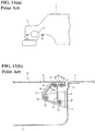
Figs. 11(a) and 11(b) show a fuel lid (hereinafter, called a lid) disclosed inPatent Document 1. Thelid 13 opens and closes a fuelfilling aperture portion 5 provided in arear fender portion 3 of a car body rear portion shown inFig. 11(a) . The fuelfilling aperture portion 5 is divided and formed by a housing, has a concave shape with front and backvertical faces 7 extending in a car width direction and right andleft side faces 11 extending in a vehicle front and back direction, and has a fuel inlet portion closed by a cap at a bottom wall of the concave shape which is omitted in the drawing. Thelid 13 is formed in aflange portion 21 wherein a front side bends inwardly in the car width direction, and includes a supportingbracket 19 provided along theflange portion 21 on a front reverse side. Then, thelid 13 is supported to be openable and closable through first andsecond link members attachment bracket 9 fixed to thevertical face 7. - In that case, in the
attachment bracket 9 and the supportingbracket 19, respectively, two supportingpins 27 and two supportingpins 35 are projected. In thefirst link member 15, both ends are formed in C-shaped supportingportions portions pin 27 of the attachment bracket and the supportingpin 27 of the supporting bracket. In thesecond link member 17, both ends are formed in C-shaped supportingportions portions pin 35 of the attachment bracket and the supportingpin 35 of the supporting bracket as well. Also, thesecond link member 17 is disposed on a backward side of thefirst link member 15, and supports a movement of thefirst link member 15 so as to regulate an opening and closing track of thelid 13 to a predetermined path. - Patent Document 1: Japanese Unexamined Patent Application Publication No.
2005-343367 - In the aforementioned lid structure, usually, in a state wherein the lid is assembled to the housing dividing the fuel filling aperture portion through the link members and the like, the housing is inserted to an inner side of an opening portion provided in a car body panel (an outer panel and the like), and is integrally mounted in an edge portion of the opening portion through a seal member. Then, when fuel is filled, after the lid comes to an open state, a cap of the fuel inlet portion provided inside the fuel filling aperture portion is removed, and then a fuel nozzle is inserted into the fuel inlet portion from a space of the fuel filling aperture portion. In the fueling operation, there is a possibility that the fuel nozzle abuts against the attachment bracket and the like protruding into the space of the fuel filling aperture portion accidentally. Naturally, in a lid open state, since the attachment bracket protrudes to the fuel filling aperture portion, it lacks a design property.
- Incidentally, as for a measure for the above, for example, there may be provided a projecting portion projecting outwardly in a circumference portion of the housing dividing the fuel filling aperture portion, and may have a lid support portion in an inner space of the projecting portion so as to keep an appearance in the lid open state (for example, Japanese Unexamined Patent Application Publication No.
2014-97712 - Objects of the present invention are to solve the aforementioned problems, and to obtain a vehicle lid device wherein the housing dividing the fuel filling aperture portion, i.e., the fuel filling aperture portion into which the fuel nozzle is inserted, has an excellent design property, and does not interfere with inserting and removing operations of the fuel nozzle relative to the fuel inlet portion on a bottom wall side of the fuel filling aperture portion. Also, the lid device which has an excellent mounting operability relative to an attachment opening portion of the car body panel can be obtained as well. Other objects will be clarified in the following explanations.
- In order to obtain the aforementioned objects, a vehicle lid device according to a first aspect of the present invention comprises a housing provided with a fuel filling aperture portion; a lid for opening and closing an opening of the housing; and a link member for connecting the lid relative to the housing to be openable and closable, and includes a base member capable of pivotally supporting the link member to be turnable, and a concave portion provided in the housing and capable of receiving the base member.
- The aforementioned vehicle lid device according to the first aspect of the present invention may be formed in aspects specified hereinafter.
- (A) An aspect wherein an engaging portion is formed in either one of the base member or the concave portion, an engaged portion engaging the engaging portion is formed in the other of the base member or the concave portion, and the base member is mounted relative to the concave portion through an engagement of the engaging portion and the engaged portion. According to the aspect, an excellent assembling property can be obtained, thereby reducing the number of assembly processes as well.
- (B) An aspect wherein the engaging portion and the engaged portion are formed by a projecting piece portion and a groove portion which can engage with each other. According to the aspect, the base member can be attached to the concave portion by a sliding operation in a direction along the groove portion, i.e., one-touch operation.
- (C) An aspect wherein the link member is formed by a first link member and a second link member, and an urging device is disposed between the first link member and the second link member. According to the aspect, a turning track of the lid can be easily controlled in the same manner as in the
Patent Document 1. Thereby, even if the base member or a shaft portion of the lid is disposed inside the housing, interference relative to the housing or a car body can be avoided. Also, an urging force of the urging device acts between each link so as to prevent wobbling of the link. - (D) An aspect wherein when the lid opens, an outer face of the first or second link member becomes approximately the same one face as a corresponding portion of the housing or the lid. According to the aspect, an appearance can be improved.
- (E) An aspect wherein a base end of the link member is connected relative to the base member to be turnable through the shaft portion, and a shaft end of the shaft portion is shielded (becomes invisible) by an inner wall face of the concave portion. According to the aspect, in the base end of the link member, the shaft portion of the base member becomes invisible so as to improve the appearance, and a possibility of an unintentional separation can be solved.
- (F) An aspect wherein the housing, the lid, the link member, and the base member are formed by a resin molded article. According to the aspect, a resin can reduce the weight.
- The vehicle lid device according to a second aspect of the present invention is specified from a viewpoint of a mounting structure to a car body panel, and comprises the housing provided with the fuel filling aperture portion; the lid for opening and closing the opening of the housing; and the link member for connecting the lid relative to the housing to be openable and closable, and after integrally assembling the aforementioned three portions, a seal member is attached in a state interposed relative to an opening portion of an outer panel of a vehicle. The link member is formed by the first link member and the second link member, and the shaft portion pivotally supporting the link member to be turnable relative to the housing side is positioned on an inner side of the housing.
- In the vehicle lid device according to the first aspect of the present invention, as for the lid device including the housing, the lid, and the link member for connecting the lid to the housing, the link member is pivotally supported in the base member disposed in the concave portion of the housing so as to eliminate or reduce a protruding member or a protruding portion into the housing compared to a conventional structure, thereby providing an excellent design property of a space inside the housing, i.e., the fuel filling aperture portion, and improving an operability of inserting the fuel nozzle into a fuel inlet portion provided on a bottom wall side of the housing or pulling out the fuel nozzle.
- In the vehicle lid device according to the second aspect of the present invention, after the three portions of the housing, the lid, and the link member are assembled, in an attaching operation of the three portions relative to an attachment frame mounted in an outer panel of a car body by interposing the seal member, as for the housing, a portion protruding outwardly from a circumference can be eliminated as much as possible, so that when the housing is inserted into the opening portion of the car body, the housing can be straightly inserted, thereby solving a possibility that the seal member may be twisted or displaced accompanied by the insertion.
-
-
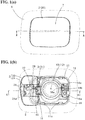
Figs. 1(a) and 1(b) show a state wherein a lid device of an embodiment is mounted on a car body side, whereinFig. 1(a) is a diagram showing a closed state of a lid, andFig. 1(b) is a diagram showing an open state of the lid, and shows one portion of a rear fender. -
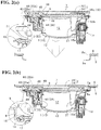
Figs. 2(a) and 2(b) are cross-sectional views corresponding to line A-A inFig. 1(a) , whereinFig. 2(a) is a drawing showing a state before mounting to an attachment frame on a car body panel side, andFig. 2(b) is a drawing showing a state mounted in the attachment frame. -
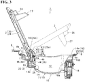
Fig. 3 is a cross-sectional view corresponding to line A1-A1 inFig. 1(b) . -
Figs. 4(a) to 4(e) show the lid device, whereinFig. 4(a) is a top view,Fig. 4(b) is a left side view,Fig. 4(c) is a front view,Fig. 4(d) is a right side view, andFig. 4(e) is a bottom view. -
Fig. 5 is a schematic exploded view showing a structure of the lid device. -
Figs. 6(a) to 6(c) show a structure of the lid, whereinFig. 6(a) is an exploded view showing the lid and a support member mounted on a reverse face of the lid, andFigs. 6(b) and 6(c) are end views of the support member viewed from a B direction and a C direction inFig. 6(a) . -
Fig. 7(a) is a perspective view showing a state wherein a cylinder member is mounted in a housing, andFig. 7(b) is a perspective view showing a state wherein the support member is assembled to the housing further. -
Fig. 8(a) is a perspective view showing a state wherein a lock device is mounted in the housing, andFig. 8(b) is an enlarged view of a D portion inFig. 8(a) . -
Fig. 9(a) is an assembly explanatory view of a first arm member relative to a base member mounted in a concave portion, andFig. 9(b) is an assembly explanatory view of a second arm member relative to the base member of the concave portion, in the aforementioned enlarged view of the D portion. -
Figs. 10(a), 10(b), and 10(c) are a top view, a side view, and a bottom view in a state wherein the first and second arm members are connected to the support member. -
Figs. 11(a) and 11(b) show a disclosure inPatent Document 1, whereinFig. 11(a) is an explanatory view in a non-usage state wherein the lid device is mounted in a car body panel, andFig. 11(b) is a cross-sectional view taken along line A-A inFig. 11(a) . - The best mode of the present invention will be explained with reference to the attached drawings. In an explanation, after a structure of a lid device according to the present invention is clarified, operation characteristics will be described.
- (Structure) In
Fig. 1(a) to Fig. 5 , alid device 7 comprises an approximately container-like housing 1 dividing a fuelfilling aperture portion 12 and opening upwardly; alid 2 opening and closing an upper opening of thehousing 1; abase member 3 mounted in an inner circumference of thehousing 1; alink member 4 supporting thelid 2 relative to thebase member 3 to be openable and closable; and acylindrical member 5 connected to a bottom wall of thehousing 1 to insert a fuel nozzle from the fuelfilling aperture portion 12. Also, thelid 2 is formed by alid member 20 and asupport member 24 mounted on a reverse face of the lid member. Thelink member 4 is formed by first andsecond link members housing 1, the lid 2 (thelid member 20 and the support member 24), thebase member 3, the link member 4 (thefirst link member 4A and thesecond link member 4B), and thecylindrical member 5 are respectively resin injection molding members. - In other words, in the
lid device 7, thelid 2 is supported relative to thehousing 1 to be turnable through thebase member 3 and twolink members lid 2 is locked in a closed state inFigs. 2(a) and 2(b) by alock device 18 mounted on an outer circumference of thehousing 1, and, for example, when thelock device 18 is operated to release the locking through an opener inside a vehicle compartment, or the locking is released by an association with a release operation of a door lock, thelid 2 slightly opens from the closed state inFigs. 2(a) and 2(b) against an urging force of an urging device (torsion spring) 6 by the later-described push lifter 6a. Then, in a middle of turning thelid 2 in an opening direction by hand, an urging direction of the urgingdevice 6 is reversed, and after that, thelid 2 turns in a fully opening direction by the urging force of the urgingdevice 6. Hereinafter, the details will be clarified. - As shown in
Fig. 5 , in thehousing 1, aflange portion 11 protrudes on an upper circumference of acylindrical portion 10. Thecylindrical portion 10 comprises a circular throughhole 13 provided at the bottom wall; aconcave portion 14 provided in the inner circumference and having a size which can receive thebase member 3; acavity portion 15 wherein a right to left or front to back portion of theconcave portion 14 is formed lower by one step; acavity portion 16 located in the inner circumference, positioned in a portion facing theconcave portion 14, and formed lower by step; a plurality ofelastic locking claws 17 projected on the outer circumference; and thelock device 18 locking thelid 2 in the closed state (seeFigs. 2(a) and 2(b) ). Also, theflange portion 11 has an approximately rectangular shape, and as shown in enlarged views inFigs. 2(a) and 2(b) , includes aseal member 19 integrally mounted in a tip circumference portion. Thesymbol 11a shown inFigs. 4(a), 4(b), 4(d), and 4(e) represents a plurality of projections provided on theflange portion 11 for receiving thelid 2. - Among those, the
cylindrical member 5 is connected to the through hole 13 (seeFig. 5 ). Thecylindrical member 5 communicates with a fuel tank side which is not shown in the drawings by a connecting pipe. Then, a fuel nozzle for fueling is carried out with a fueling operation in a state wherein the fuel nozzle for fueling is inserted into a cylinder of thecylindrical member 5 from the fuel fillingaperture portion 12. - As shown in
Fig. 8(a) , a top portion of theconcave portion 14 communicates with thecavity portion 15, and theconcave portion 14 includes projectingpiece portions 14a which are engaging portions respectively provided on facing inside surfaces and horizontally protruding;control projections 14b protruding up and down and positioning thebase member 3; and apedestal 14c protruding from a bottom face on a back side and having a through hole. The projectingpiece portions 14a engagegroove portions 37 provided on bothside portions 31 of the later-describedbase member 3 so as to allow thebase member 3 to be mounted in theconcave portion 14. - As inferred from
Fig. 3 , thecavity portion 15 is a portion for allowing a base end side of thelid 2 to move out when thelid 2 turns from the closed state inFigs. 2(a) and 2(b) to an open state. As shown inFig. 7(a) , in thecavity portion 16, on a bottom wall, there are respectively projected apush lifter 16a, and aprojection 16b and aprojection 16c dividing a predetermined gap therebetween. Incidentally, thepush lifter 16a (the lifter is disclosed in, for example, Japanese Unexamined Patent Application Publication No.2015-105062 lid 2 to be pinched with one's fingers and the like by slightly pushing thelid 2 up further to rise when thelid 2 is opened. Thesymbol 16d represents a through hole located in an inner circumference of thecylindrical portion 10, and provided at a portion on a side lower than thecavity portion 15. - As shown in
Figs. 4(a), 4(b), and 4(e) , each elastic lockingclaw 17 is divided and formed by an approximately U-shaped slit, and is projected by maintaining a predetermined gap between theelastic locking claw 17 and theflange portion 11. Then, as shown inFigs. 2(a) and 2(b) , when thelid device 7 is mounted on anattachment frame 9 fixed to anouter panel 8, each elastic lockingclaw 17 passes an opening portion 9a of theattachment frame 9 while elastically reducing a diameter, and simultaneously restores to its original state so as to allow thelid device 7 to be mounted relative to theattachment frame 9 in a state wherein an edge portion of the opening portion 9a is clamped between the edge portion of the opening portion 9a and theflange portion 11. - In other words, in the
outer panel 8, there is provided anopening portion 8a having a size corresponding to thelid 2. Theattachment frame 9 includes the opening portion 9a which allows thecylindrical portion 10 to pass through, and is located on an inner face of theouter panel 8, and connected to a peripheral edge portion of theopening portion 8a by welding and the like. Also, as shown in the enlarged view inFig. 2(b) , thelid device 7 is mounted on theattachment frame 9 in a state wherein the edge portion of the opening portion 9a is clamped between (the projection provided on a lower face of) theflange portion 11 and the lockingclaw 17. - The
lock device 18 is formed by a known lock mechanism including alock member 18a driven to protrude and recede. Then, thelock device 18 is located on the outer circumference of thecylindrical portion 10, and mounted on a lower side of thecavity portion 16 so as to switch thelid 2 to be locked in the closed state when thelock member 18a protrudes from the aforementioned throughhole 16d, and thelid 2 to be in the open state when thelock member 18a recedes from the throughhole 16d. - In the
lid 2, as shown inFig. 1(a) ,Fig. 5 , andFig. 6(a) , thelid member 20 is formed by a rectangular shape which can be housed in theopening portion 8a of theouter panel 8 approximately without a gap. As shown inFig. 6(a) , on the reverse face of thelid member 20, there are included aframe portion 20a positioning thesupport member 24 on an inner side; a plurality oflower piece portions 22 projected on inner faces on both sides and front angle portions of theframe portion 20a; and a plurality ofupper piece portions 23 forming a clamping portion between theupper piece portion 23 and thelower piece portion 22. In thesupport member 24, a back side is formed by a pair ofarm portions 25. Eacharm portion 25 is formed to become thicker up and down as moving to an end side from a middle in the front and back. On a facing inner face of eacharm portion 25, there are provided ashaft hole 25a and ashaft hole 25b positioned in front and back on a coaxial line, respectively. - As shown in
Fig. 5 , on an upper face side of thesupport member 24, both sides and a front side in a longitudinal direction are formed in an L-shaped step, and the upper face side of thesupport member 24 includes a plurality ofpiece portions 26 protruding to a vertical face of the L shape and an upper side of thearm portion 25. As shown inFig. 6(a) , a lower face side of thesupport member 24 includes apedestal portion 24a projected in a corner portion on one front side; anengagement piece 27 projected in an approximately middle of a plate width on a front side; asmall projection 28 projected further forward from one portion of a front end face of theengagement piece 27; and aguide piece 29 projected on the other front side in a state connected to a corresponding side face of theengagement piece 27 and thesmall projection 28. - Among those, each
piece portion 26 is assembled in such a way so as to be clamped between the aforementionedlower piece portion 22 andupper piece portion 23, so that thesupport member 24 is attached to the reverse face of thelid member 20. When thelid 2 is switched from the open state to the closed state, thepedestal portion 24a abuts against theaforementioned buffer projection 16a. Theengagement piece 27 includes alocking hole 27a passing through back and forth, and theaforementioned lock member 18a is inserted and engaged so as to lock thelid 2 in the closed state. Thesmall projection 28 fits into the gap between theaforementioned projections lid 2 so as to control an unintentional oscillation of thelid 2. Theguide piece 29 slides along a curved surface formed in a border portion between thecavity portion 16 and thecylindrical portion 10 in a process wherein thelid 2 is switched from the open state to the closed state, and from the closed state to the open state so as to maintain smooth turning of thelid 2. - The
base member 3 has a size which can be approximately housed in the concave portion 14 (seeFig. 8(b) ). Also, as shown inFig. 3 ,Fig. 5 , andFig. 8(b) , thebase member 3 includes abottom wall 30;side walls bottom wall 30 and forming an upper side thinner than a lower side; aback wall 32 connecting back end sides of bothside walls 30 so as to make an inside of a concave portion difficult to be seen; a boss 33 (seeFig. 5 ) projected on an upper face of thebottom wall 30 and having a through hole in an up-and-down direction; aleg 34 integrated with theback wall 32 and protruding downwardly from thebottom wall 30; shaft holes 35 and 36 provided above and below bothside walls 31 and respectively positioned on a coaxial line; andgroove portions 37 which are engaged portions located on bothside walls 31, provided on a side lower than theshaft hole 36, and horizontally extending from a front end to just before a back end. - The
aforementioned base member 3 is pushed into theconcave portion 14 such that thegroove portions 37 on both sides fit into the projectingpiece portions 14a. Then, thebase member 3 is positioned in a state wherein the upper side formed thinner in eachside wall 31 abuts against thecontrol projection 14b, and thebase member 3 is mounted on theconcave portion 14 by an engagement of the projectingpiece portion 14 and thegroove portion 37. In this mounted state, in thebase member 3, a front side of thebottom wall 30 is supported in thepedestal 14c, and a back side of thebottom wall 30 is supported on the bottom face of theconcave portion 14 through theleg 34 so as to maintain a horizontal state. Also, as shown inFig. 3 , the through hole of theboss 33 communicates with the through hole of thepedestal 14c. Incidentally, in the structure, as necessary, it is designed such that a fastener such as a screw and the like is screwed into the through hole of theboss 33 from the through hole of thepedestal 14c from an outside or inside so that thebase member 3 does not unintentionally come off from theconcave portion 4. However, such a fastener can be omitted. - The
first link member 4A and thesecond link member 4B support thelid 2 or thesupport member 24 to be turnable relative to thebase member 3. Namely, as shown inFig. 5 ,Fig. 9(a) , andFigs. 10(a) and 10(c) , thefirst link member 4A includes aplate portion 40 having an approximately rectangular shape; upper protrudingportions 41 and lower protrudingportions 42 located on both upper sides and both lower sides of theplate portion 40, and projected upwardly or downwardly;shaft portions portions 41; andshaft portions portions 42. On upper and lower faces of theplate portion 40, there is provided a plurality of concaves or notch portions. - In the
aforementioned link member 4A, therespective shaft portions 44 on the lower side are fitted and connected to the corresponding shaft holes 36 of the base member to be turnable, and therespective shaft portions 43 on the upper side are fitted and connected to thecorresponding shaft holes 25a of the support member to be turnable. - As shown in
Fig. 5 ,Fig. 9(b) , andFig. 10(c) , thesecond link member 4B includes aplate portion 45 having an approximately L shape in a side view;shaft portions plate portion 45 on a coaxial line; andprojections 48 located further both sides lower than theshaft portions 47 and projected on a coaxial line. In a process wherein thelink member 4B turns as a supporting point of theshaft portions 47 fitted to the shaft holes 35 of thebase member 3 attached to theconcave portion 14, for example, theprojections 48 slidingly contact a facing portion of thebase member 3 so as to reduce a frictional resistance or allow wobbling to be easily absorbed. Also, in theplate portion 45, as shown inFig. 3 , in the open state of thelid 2, an outer face disposed on a fuel fillingaperture portion 12 side is formed on a flat surface (design surface), and in an inner face on an opposite side, a plurality of ribs is provided on an upper side, and a cavity is formed on a lower side. In the cavity,support shaft portions 49 for holding a spring are projected on both inside faces on a coaxial line. - In the
aforementioned link member 4B, therespective shaft portions 47 on the lower side are fitted and connected to the corresponding shaft holes 35 of the base member to be turnable, and therespective shaft portions 46 on the upper side are fitted and connected to the corresponding shaft holes 25b of the support member to be turnable. At that time, a coil spring of the urgingdevice 6 is assembled in a state of holding a coil portion in thesupport shaft portions 49 on both sides in the second link member, and one end 6a is disposed inside the cavity of theplate portion 45, and theother end 6b is disposed on the lower side of thefirst link member 4A. - (Operation) Next, the operation characteristics of the
lid device 7 are clarified with reference toFig. 1(a) to Fig. 3 . - (1) First,
Fig. 2(a) shows an attaching operation wherein thelid device 7 assembled in the aforementioned manner is fixed to theattachment frame 9 mounted on theouter panel 8. In the structure, thelid device 7 includes thelock device 18 around thecylindrical portion 10, however, thelock device 18 is disposed on an inner side than theflange portion 11. Thus, as for thelid device 7 or thehousing 1, a portion protruding outwardly from a circumference is eliminated as much as possible, so that when inserted into an opening portion (theopening portion 8a of the outer panel, and theopening portion 9 of the attachment frame) of a car body, thelid device 7 or thehousing 1 can be straightly inserted, thereby solving a possibility such that theseal member 9 mounted on theflange portion 11 may be twisted or displaced accompanied by the insertion as in a conventional seal member, and improving an operation efficiency and a quality. - (2) Also, when the
lid device 7 is inserted into the opening portion 9a and pressed, each lockingclaw 17 passes through the opening portion 9a accompanied by a displacement in a diameter-reduction direction, and simultaneously restores to its original state so as to clamp the edge portion of the opening portion 9a between the edge portion of the opening portion 9a and (the projection provided on the lower face of) theflange portion 11. Namely, in the attaching structure, thelid device 7 can be attached by one-touch operation. Also, in an attached state of thelid device 7, as shown in the enlarged view inFig. 2(b) , theseal member 19 is pressed against a corresponding portion of theattachment frame 9, and maintains water-tightness of the opening portion 9a. - (3)
Fig. 2(b) andFig. 3 show thelid device 7 in a condition mounted on a car body side. Thelid device 7 is locked by thelock device 18 in the closed state of thelid 2, and as in a conventional manner, thelid device 7 closes the fuel fillingaperture portion 12, and is disposed on the same face as theouter panel 8. When thelock device 18 is unlocked, thelid 2 is pressed in the opening direction against the urging force of the urgingdevice 6 by the push lifer 6a so as to slightly open. From that state, when an operator turns thelid 2 in the opening direction by hand, in the middle (an intermediate position) of turning thelid 2, the urging direction of the urgingdevice 6 is reversed, and after that (the intermediate position), thelid 2 turns in the opening direction through the link member 4 (first andsecond link members device 6 until thelid 2 fully opens.
Operations of bothlink members Patent Document 1, and for an opening and closing track of thelid 2, an original opening and closing track by thefirst link member 4A is controlled or supported by thesecond link member 4B, so that the opening and closing track of thelid 2 is corrected to be compact so as to prevent thelid 2 from interfering with theouter panel 8 at an opening and closing time. Consequently, in the structure, even if therespective shaft portions link members housing 1, thelid 2 does not interfere with theouter panel 8. - (4) Also, in the structure, in an open state wherein the
lid 2 opens in full lines inFig. 3 through the link member 4 (first andsecond link members first link member 4A abuts against the inside of the L shape of theplate member 45 of thesecond link member 4B, and an edge portion on the base end side of thelid 2 abuts against theplate portion 40 of thefirst link member 4A. Thereby, thelid 2 is stably held in an open state wherein thelid 2 opens at 90 degrees or more. Also, the structure excels in the appearance because in the open state inFig. 3 , thefirst link member 4A is in a state clamped between thelid 2 and thesecond link member 4B so as to be difficult to be seen; thesecond link member 4B includes the aforementioned flat design surface on the fuel fillingaperture portion 12 side; the design surface becomes approximately the same surface (continuous surface) as theback wall 32 of thebase member 3 integrally assembled with thehousing 1, and a corresponding portion of thelid 2; and the like. - (5) Incidentally, the urging
device 6 allows thelid 2 to turn from a middle position in the aforementioned opening direction to a fully open position by the urging force through thelink member 4. Also, when thelid 2 is operated to turn to the middle position against the urging force from the fully open position, thelid 2 reverses, and after that, thelid 2 is switched to the closed state by the urging force through thelink member 4. Such an urging structure improves opening and closing operations of thelid 2, and can absorb wobbling by vibrations in the closed state and the open state. - (6) Incidentally, in the
aforementioned lid device 7, main structural members, i.e., thehousing 1, the lid 2 (thelid member 20 and the support member 24), thebase member 3, the link member 4 (thefirst link member 4A and thesecond link member 4B), and thecylindrical member 5 are made of resin so as to excel in mass productivity and easily provide a lightweight device. - As described above, the lid device of the present invention can be variously modified except for specified requirements within a range described in the invention. For example, as for the
lid 2, thesupport member 24 is mounted on thelid member 20; however, a portion corresponding to thesupport member 24 may be integrally formed in thelid member 20. Also, as for theseal member 19, a separately formed member is attached to theflange portion 11 of the housing; however, the seal member may be integrally formed in theflange portion 11 by two-color formation. Also, the engaging portion (the projectingpiece portion 14a) can be provided on a base member side, and the engaged portion (the groove portion 37) can be provided on aconcave portion 14 side as well. -
- 1 ... a housing (10 is a cylindrical portion, and 11 is a flange portion)
- 2 ... a lid (20 is a lid member, and 24 is a support member)
- 3 ... a base member (30 is a bottom wall, 31 is side walls, and 32 is a back wall)
- 4 ... a link member (4A is a first link member, and 4B is a second link member)
- 5 ... a cylindrical member
- 6 ... an urging device (6a is one end, and 6b is the other end)
- 7 ... a lid device
- 8 ... an outer panel (8a is an opening portion)
- 9 ... an attachment frame (9a is an opening portion)
- 12 ... a fuel filling aperture portion
- 14 ... a concave portion (14b is control projections)
- 14a ... projecting piece portions (engaging portions)
- 19 ... a seal member
- 35 ... shaft holes
- 36 ... shaft holes
- 37 ... groove portions (engaged portions)
- 43 ... shaft portions
- 44 ... shaft portions
- 46 ... shaft portions
- 47 ... shaft portions
- 48 ... projections
- 49 ... support shaft portions
- Incidentally, all contents of the specification, claims, drawings, and abstract of Japanese Patent Applications No.
2015-174030 filed on September 3, 2015
Claims (8)
- A vehicle lid device, comprising:a housing having a fuel filling aperture portion;a lid opening and closing an opening of the housing;a link member connecting the lid to the housing to be openable and closable;a base member pivotally supporting the link member turnably, anda concave portion provided in the housing and capable of receiving the base member.
- A vehicle lid device according to claim 1, wherein an engaging portion is formed in either the base member or the concave portion, and an engaged portion engaging the engaging portion is formed in the other of the base member or the concave portion, and the base member is mounted relative to the concave portion through an engagement of the engaging portion and the engaged portion.
- A vehicle lid device according to claim 2, wherein the engaging portion and the engaged portion are formed by a projecting piece portion and a groove portion which can engage with each other.
- A vehicle lid device according to any of claims 1 to 3, wherein the link member is formed by a first link member and a second link member, and an urging device is disposed between the first link member and the second link member.
- A vehicle lid device according to claim 4, wherein when a lid opens, an outer face of the first or second link member becomes approximately a same one face as a corresponding portion of the housing or the lid.
- A vehicle lid device according to any of claims 1 to 5, wherein a base end of the link member is connected to the base member to be turnable through a shaft portion, and a shaft end of the shaft portion is shielded by an inner wall face of the concave portion.
- A vehicle lid device according to any of claims 1 to 6, wherein the housing, the lid, the link member, and the base member are formed by a resin molded article.
- A vehicle lid device, comprising:a housing having a fuel filling aperture portion;a lid opening and closing an opening of the housing; anda link member connecting the lid to the housing to be openable and closable, and after integrally assembling the three portions, attaching in a state wherein a seal member is disposed relative to an opening portion of an outer panel of a vehicle,wherein the link member is formed by a first link member and a second link member, and a shaft portion pivotally supporting the link member to be turnable relative to a housing side is positioned on an inner side of the housing.
Applications Claiming Priority (2)
| Application Number | Priority Date | Filing Date | Title |
|---|---|---|---|
| JP2015174030A JP6466293B2 (en) | 2015-09-03 | 2015-09-03 | Vehicle lid device |
| PCT/JP2016/075357 WO2017038833A1 (en) | 2015-09-03 | 2016-08-30 | Vehicle lid device |
Publications (3)
| Publication Number | Publication Date |
|---|---|
| EP3345781A1 true EP3345781A1 (en) | 2018-07-11 |
| EP3345781A4 EP3345781A4 (en) | 2019-06-12 |
| EP3345781B1 EP3345781B1 (en) | 2021-12-15 |
Family
ID=58188834
Family Applications (1)
| Application Number | Title | Priority Date | Filing Date |
|---|---|---|---|
| EP16841864.8A Active EP3345781B1 (en) | 2015-09-03 | 2016-08-30 | Vehicle lid device |
Country Status (5)
| Country | Link |
|---|---|
| US (1) | US10513174B2 (en) |
| EP (1) | EP3345781B1 (en) |
| JP (1) | JP6466293B2 (en) |
| CN (1) | CN107921867B (en) |
| WO (1) | WO2017038833A1 (en) |
Families Citing this family (14)
| Publication number | Priority date | Publication date | Assignee | Title |
|---|---|---|---|---|
| JP6466293B2 (en) | 2015-09-03 | 2019-02-06 | 株式会社ニフコ | Vehicle lid device |
| JP6689236B2 (en) * | 2017-07-14 | 2020-04-28 | 株式会社ニフコ | Vehicle lid device |
| JP6709760B2 (en) * | 2017-07-14 | 2020-06-17 | 株式会社ニフコ | Vehicle lid device |
| JP6837399B2 (en) * | 2017-08-07 | 2021-03-03 | 株式会社ニフコ | Lid device |
| JP7137898B2 (en) * | 2017-09-29 | 2022-09-15 | ダイハツ工業株式会社 | fuel lid |
| KR102484859B1 (en) * | 2017-12-12 | 2023-01-05 | 현대자동차주식회사 | Radiatir grille rechargeable door apparatus for a vehicle |
| JP7037998B2 (en) * | 2018-04-19 | 2022-03-17 | 本田技研工業株式会社 | Transport equipment |
| JP6926031B2 (en) * | 2018-06-05 | 2021-08-25 | 株式会社ニフコ | Lid urging structure |
| DE102018125209A1 (en) * | 2018-10-11 | 2020-04-16 | Bayerische Motoren Werke Aktiengesellschaft | Tank or tailgate assembly |
| JP7143562B2 (en) * | 2019-02-14 | 2022-09-29 | 豊田合成株式会社 | Lid open/close structure |
| JP7156187B2 (en) * | 2019-06-28 | 2022-10-19 | 豊田合成株式会社 | Lid open/close structure |
| CN116209616A (en) * | 2020-10-08 | 2023-06-02 | 三菱自动车工业株式会社 | Cover device for vehicle |
| JP7258934B2 (en) * | 2021-03-17 | 2023-04-17 | 本田技研工業株式会社 | Vehicle opening/closing structure |
| DE102021122952A1 (en) | 2021-09-06 | 2023-03-09 | Dr. Ing. H.C. F. Porsche Aktiengesellschaft | Charging flap module or tank flap module of a motor vehicle |
Family Cites Families (34)
| Publication number | Priority date | Publication date | Assignee | Title |
|---|---|---|---|---|
| JPS5815580Y2 (en) | 1978-04-28 | 1983-03-29 | 日産自動車株式会社 | Pantograph type opening/closing device |
| JPH0415532Y2 (en) * | 1986-06-28 | 1992-04-08 | ||
| JPH0717561Y2 (en) * | 1989-03-23 | 1995-04-26 | アラコ株式会社 | Vehicle fuel lid |
| US5145081A (en) * | 1990-10-03 | 1992-09-08 | Trilby, Ltd. | Capless closure for a fuel tank filler pipe |
| JPH0513147A (en) * | 1991-07-05 | 1993-01-22 | Ngk Spark Plug Co Ltd | Spark plug |
| JP2530321Y2 (en) * | 1992-02-07 | 1997-03-26 | アラコ株式会社 | Movable fuel lid mounting structure |
| JPH0613924U (en) | 1992-07-29 | 1994-02-22 | トヨタ車体株式会社 | Filler structure |
| JP3572362B2 (en) * | 1994-06-13 | 2004-09-29 | 日産自動車株式会社 | Automotive fuel filler structure |
| DE29605297U1 (en) | 1996-03-21 | 1996-05-23 | Mittelhäuser, Bernhard, 30900 Wedemark | Device for covering the filler neck on motor vehicles by means of a fuel filler flap |
| JP3345330B2 (en) | 1997-12-25 | 2002-11-18 | 象印マホービン株式会社 | Liquid container stopper |
| US7258386B2 (en) * | 1999-04-27 | 2007-08-21 | 89908, Inc. | Fuel door assembly |
| JP2005343367A (en) * | 2004-06-04 | 2005-12-15 | Nissan Motor Co Ltd | Fuel lid mounting structure |
| KR20060062390A (en) * | 2004-12-03 | 2006-06-12 | 현대자동차주식회사 | Structure of fuel filler door for automobile |
| CN2866226Y (en) * | 2005-11-29 | 2007-02-07 | 吴伯明 | Multifunction vehicle fuel oil tank cover |
| JP4207964B2 (en) * | 2006-01-27 | 2009-01-14 | トヨタ自動車株式会社 | Gas fuel filling lid device for vehicle |
| JP4774538B2 (en) * | 2007-10-05 | 2011-09-14 | 本田技研工業株式会社 | Fuel pump mounting structure |
| CN103395364B (en) * | 2008-02-22 | 2016-03-16 | 本田技研工业株式会社 | For the lid structure of the fuel filler tube opening of vehicle |
| DE102008047464A1 (en) * | 2008-09-17 | 2010-04-15 | Dr.Ing.H.C.F.Porsche Aktiengesellschaft | Tank flap module for motor vehicle, has damping medium provided with stop cushion lying inside and arranged in hinge arm of hinge, where stop cushion is aligned to tank filler tray with front surface of stop wall |
| KR101124954B1 (en) | 2010-06-28 | 2012-03-27 | 현대자동차주식회사 | Cover apparatus for battery charge port of electric vehicle |
| JP5780121B2 (en) * | 2011-11-02 | 2015-09-16 | 三菱自動車工業株式会社 | Lid mounting structure |
| JP2013123930A (en) * | 2011-12-13 | 2013-06-24 | Molten Corp | Fuel filler lid device |
| CN202507919U (en) * | 2012-02-24 | 2012-10-31 | 长城汽车股份有限公司 | Automobile oil filler cap structure |
| CN202716981U (en) * | 2012-07-10 | 2013-02-06 | 光阳工业股份有限公司 | Fuel tank lock |
| DE102012014370A1 (en) * | 2012-07-20 | 2013-03-14 | Daimler Ag | Holding arrangement of flap element mounted on skin paneling portion of motor vehicle, has retaining element through which flap element is set to closed position so that gap between flap element and paneling portion is sealed partially |
| JP5962496B2 (en) * | 2012-12-21 | 2016-08-03 | 三菱自動車工業株式会社 | Lid device |
| CN203222043U (en) | 2013-04-12 | 2013-10-02 | 比亚迪股份有限公司 | Automotive cover board assembly |
| KR20140137779A (en) * | 2013-05-24 | 2014-12-03 | 현대자동차주식회사 | Variable valve |
| CN105745110B (en) | 2013-11-19 | 2018-07-17 | 伊利诺斯工具制品有限公司 | Fuel stuffer component for vehicle |
| CN203727164U (en) * | 2013-12-31 | 2014-07-23 | 众泰控股集团有限公司 | Oil filler cap |
| DE202014002556U1 (en) * | 2014-03-22 | 2015-06-26 | GM Global Technology Operations LLC (n. d. Ges. d. Staates Delaware) | Flap arrangement for a motor vehicle |
| CN204222638U (en) * | 2014-10-11 | 2015-03-25 | 华德塑料制品有限公司 | Vehicle oil filler open and close rotating mechanism |
| US9376012B2 (en) * | 2014-10-13 | 2016-06-28 | Srg Global, Inc. | Vehicle fuel filler system seal |
| CN204567272U (en) * | 2015-04-29 | 2015-08-19 | 神龙汽车有限公司 | A kind of automobile plastic filler cap |
| JP6466293B2 (en) | 2015-09-03 | 2019-02-06 | 株式会社ニフコ | Vehicle lid device |
-
2015
- 2015-09-03 JP JP2015174030A patent/JP6466293B2/en active Active
-
2016
- 2016-08-30 WO PCT/JP2016/075357 patent/WO2017038833A1/en active Application Filing
- 2016-08-30 CN CN201680050866.0A patent/CN107921867B/en active Active
- 2016-08-30 EP EP16841864.8A patent/EP3345781B1/en active Active
- 2016-08-30 US US15/753,078 patent/US10513174B2/en active Active
Also Published As
| Publication number | Publication date |
|---|---|
| WO2017038833A1 (en) | 2017-03-09 |
| US20180236870A1 (en) | 2018-08-23 |
| US10513174B2 (en) | 2019-12-24 |
| JP2017047827A (en) | 2017-03-09 |
| CN107921867B (en) | 2021-01-26 |
| CN107921867A (en) | 2018-04-17 |
| JP6466293B2 (en) | 2019-02-06 |
| EP3345781A4 (en) | 2019-06-12 |
| EP3345781B1 (en) | 2021-12-15 |
Similar Documents
| Publication | Publication Date | Title |
|---|---|---|
| EP3345781B1 (en) | Vehicle lid device | |
| EP2562035B1 (en) | Cup holder | |
| US11603683B2 (en) | Lid opening and closing device for vehicle | |
| US20080111417A1 (en) | Child seat anchor apparatus and partition trim | |
| KR101703143B1 (en) | console arm rest device having guide unit for noise prevention | |
| MX2015000354A (en) | Sliding door for a storage bin in a vehicle center floor console. | |
| EP3653425B1 (en) | Lid device for vehicle | |
| JP2013018403A (en) | Roof apparatus for vehicle | |
| US20140131357A1 (en) | Lid opening/closing mechanism and storage device | |
| US6899364B2 (en) | Stopper structure in a glove box | |
| JP6709827B2 (en) | Vehicle lid device | |
| KR101784601B1 (en) | Sliding lid structure for container | |
| KR100465121B1 (en) | article storage apparatus | |
| US11279224B2 (en) | Lid opening and closing device for vehicle | |
| CN112088104A (en) | Lid loading structure | |
| JP6371104B2 (en) | Assembly structure and vehicle interior parts | |
| JP2006035975A (en) | Supporting structure of opening/closing type pocket | |
| KR101747819B1 (en) | Push-type glove box | |
| JP6886373B2 (en) | Lock device | |
| KR101823887B1 (en) | Structure of flush glass | |
| KR101619985B1 (en) | Hinge device of towing hook cap for bumper cover | |
| JP2014095241A (en) | Latch changeover device for sub opening/closing body for vehicle | |
| JP5881165B2 (en) | Door panel lock device | |
| JP5093845B2 (en) | Opening and closing pocket support structure | |
| JP2008068638A (en) | Storage device for vehicle |
Legal Events
| Date | Code | Title | Description |
|---|---|---|---|
| STAA | Information on the status of an ep patent application or granted ep patent |
Free format text: STATUS: THE INTERNATIONAL PUBLICATION HAS BEEN MADE |
|
| PUAI | Public reference made under article 153(3) epc to a published international application that has entered the european phase |
Free format text: ORIGINAL CODE: 0009012 |
|
| STAA | Information on the status of an ep patent application or granted ep patent |
Free format text: STATUS: REQUEST FOR EXAMINATION WAS MADE |
|
| 17P | Request for examination filed |
Effective date: 20180220 |
|
| AK | Designated contracting states |
Kind code of ref document: A1 Designated state(s): AL AT BE BG CH CY CZ DE DK EE ES FI FR GB GR HR HU IE IS IT LI LT LU LV MC MK MT NL NO PL PT RO RS SE SI SK SM TR |
|
| AX | Request for extension of the european patent |
Extension state: BA ME |
|
| DAV | Request for validation of the european patent (deleted) | ||
| DAX | Request for extension of the european patent (deleted) | ||
| A4 | Supplementary search report drawn up and despatched |
Effective date: 20190510 |
|
| RIC1 | Information provided on ipc code assigned before grant |
Ipc: B60K 15/05 20060101AFI20190506BHEP |
|
| STAA | Information on the status of an ep patent application or granted ep patent |
Free format text: STATUS: EXAMINATION IS IN PROGRESS |
|
| 17Q | First examination report despatched |
Effective date: 20200130 |
|
| STAA | Information on the status of an ep patent application or granted ep patent |
Free format text: STATUS: EXAMINATION IS IN PROGRESS |
|
| GRAP | Despatch of communication of intention to grant a patent |
Free format text: ORIGINAL CODE: EPIDOSNIGR1 |
|
| STAA | Information on the status of an ep patent application or granted ep patent |
Free format text: STATUS: GRANT OF PATENT IS INTENDED |
|
| INTG | Intention to grant announced |
Effective date: 20210719 |
|
| GRAS | Grant fee paid |
Free format text: ORIGINAL CODE: EPIDOSNIGR3 |
|
| GRAA | (expected) grant |
Free format text: ORIGINAL CODE: 0009210 |
|
| STAA | Information on the status of an ep patent application or granted ep patent |
Free format text: STATUS: THE PATENT HAS BEEN GRANTED |
|
| AK | Designated contracting states |
Kind code of ref document: B1 Designated state(s): AL AT BE BG CH CY CZ DE DK EE ES FI FR GB GR HR HU IE IS IT LI LT LU LV MC MK MT NL NO PL PT RO RS SE SI SK SM TR |
|
| REG | Reference to a national code |
Ref country code: GB Ref legal event code: FG4D Ref country code: CH Ref legal event code: EP |
|
| REG | Reference to a national code |
Ref country code: IE Ref legal event code: FG4D Ref country code: DE Ref legal event code: R096 Ref document number: 602016067473 Country of ref document: DE |
|
| REG | Reference to a national code |
Ref country code: AT Ref legal event code: REF Ref document number: 1455241 Country of ref document: AT Kind code of ref document: T Effective date: 20220115 |
|
| REG | Reference to a national code |
Ref country code: LT Ref legal event code: MG9D |
|
| REG | Reference to a national code |
Ref country code: NL Ref legal event code: MP Effective date: 20211215 |
|
| PG25 | Lapsed in a contracting state [announced via postgrant information from national office to epo] |
Ref country code: RS Free format text: LAPSE BECAUSE OF FAILURE TO SUBMIT A TRANSLATION OF THE DESCRIPTION OR TO PAY THE FEE WITHIN THE PRESCRIBED TIME-LIMIT Effective date: 20211215 Ref country code: LT Free format text: LAPSE BECAUSE OF FAILURE TO SUBMIT A TRANSLATION OF THE DESCRIPTION OR TO PAY THE FEE WITHIN THE PRESCRIBED TIME-LIMIT Effective date: 20211215 Ref country code: FI Free format text: LAPSE BECAUSE OF FAILURE TO SUBMIT A TRANSLATION OF THE DESCRIPTION OR TO PAY THE FEE WITHIN THE PRESCRIBED TIME-LIMIT Effective date: 20211215 Ref country code: BG Free format text: LAPSE BECAUSE OF FAILURE TO SUBMIT A TRANSLATION OF THE DESCRIPTION OR TO PAY THE FEE WITHIN THE PRESCRIBED TIME-LIMIT Effective date: 20220315 |
|
| REG | Reference to a national code |
Ref country code: AT Ref legal event code: MK05 Ref document number: 1455241 Country of ref document: AT Kind code of ref document: T Effective date: 20211215 |
|
| PG25 | Lapsed in a contracting state [announced via postgrant information from national office to epo] |
Ref country code: SE Free format text: LAPSE BECAUSE OF FAILURE TO SUBMIT A TRANSLATION OF THE DESCRIPTION OR TO PAY THE FEE WITHIN THE PRESCRIBED TIME-LIMIT Effective date: 20211215 Ref country code: NO Free format text: LAPSE BECAUSE OF FAILURE TO SUBMIT A TRANSLATION OF THE DESCRIPTION OR TO PAY THE FEE WITHIN THE PRESCRIBED TIME-LIMIT Effective date: 20220315 Ref country code: LV Free format text: LAPSE BECAUSE OF FAILURE TO SUBMIT A TRANSLATION OF THE DESCRIPTION OR TO PAY THE FEE WITHIN THE PRESCRIBED TIME-LIMIT Effective date: 20211215 Ref country code: HR Free format text: LAPSE BECAUSE OF FAILURE TO SUBMIT A TRANSLATION OF THE DESCRIPTION OR TO PAY THE FEE WITHIN THE PRESCRIBED TIME-LIMIT Effective date: 20211215 Ref country code: GR Free format text: LAPSE BECAUSE OF FAILURE TO SUBMIT A TRANSLATION OF THE DESCRIPTION OR TO PAY THE FEE WITHIN THE PRESCRIBED TIME-LIMIT Effective date: 20220316 |
|
| PG25 | Lapsed in a contracting state [announced via postgrant information from national office to epo] |
Ref country code: NL Free format text: LAPSE BECAUSE OF FAILURE TO SUBMIT A TRANSLATION OF THE DESCRIPTION OR TO PAY THE FEE WITHIN THE PRESCRIBED TIME-LIMIT Effective date: 20211215 |
|
| PG25 | Lapsed in a contracting state [announced via postgrant information from national office to epo] |
Ref country code: SM Free format text: LAPSE BECAUSE OF FAILURE TO SUBMIT A TRANSLATION OF THE DESCRIPTION OR TO PAY THE FEE WITHIN THE PRESCRIBED TIME-LIMIT Effective date: 20211215 Ref country code: SK Free format text: LAPSE BECAUSE OF FAILURE TO SUBMIT A TRANSLATION OF THE DESCRIPTION OR TO PAY THE FEE WITHIN THE PRESCRIBED TIME-LIMIT Effective date: 20211215 Ref country code: RO Free format text: LAPSE BECAUSE OF FAILURE TO SUBMIT A TRANSLATION OF THE DESCRIPTION OR TO PAY THE FEE WITHIN THE PRESCRIBED TIME-LIMIT Effective date: 20211215 Ref country code: PT Free format text: LAPSE BECAUSE OF FAILURE TO SUBMIT A TRANSLATION OF THE DESCRIPTION OR TO PAY THE FEE WITHIN THE PRESCRIBED TIME-LIMIT Effective date: 20220418 Ref country code: ES Free format text: LAPSE BECAUSE OF FAILURE TO SUBMIT A TRANSLATION OF THE DESCRIPTION OR TO PAY THE FEE WITHIN THE PRESCRIBED TIME-LIMIT Effective date: 20211215 Ref country code: EE Free format text: LAPSE BECAUSE OF FAILURE TO SUBMIT A TRANSLATION OF THE DESCRIPTION OR TO PAY THE FEE WITHIN THE PRESCRIBED TIME-LIMIT Effective date: 20211215 Ref country code: CZ Free format text: LAPSE BECAUSE OF FAILURE TO SUBMIT A TRANSLATION OF THE DESCRIPTION OR TO PAY THE FEE WITHIN THE PRESCRIBED TIME-LIMIT Effective date: 20211215 |
|
| PG25 | Lapsed in a contracting state [announced via postgrant information from national office to epo] |
Ref country code: PL Free format text: LAPSE BECAUSE OF FAILURE TO SUBMIT A TRANSLATION OF THE DESCRIPTION OR TO PAY THE FEE WITHIN THE PRESCRIBED TIME-LIMIT Effective date: 20211215 Ref country code: AT Free format text: LAPSE BECAUSE OF FAILURE TO SUBMIT A TRANSLATION OF THE DESCRIPTION OR TO PAY THE FEE WITHIN THE PRESCRIBED TIME-LIMIT Effective date: 20211215 |
|
| REG | Reference to a national code |
Ref country code: DE Ref legal event code: R097 Ref document number: 602016067473 Country of ref document: DE |
|
| PG25 | Lapsed in a contracting state [announced via postgrant information from national office to epo] |
Ref country code: IS Free format text: LAPSE BECAUSE OF FAILURE TO SUBMIT A TRANSLATION OF THE DESCRIPTION OR TO PAY THE FEE WITHIN THE PRESCRIBED TIME-LIMIT Effective date: 20220415 |
|
| PLBE | No opposition filed within time limit |
Free format text: ORIGINAL CODE: 0009261 |
|
| STAA | Information on the status of an ep patent application or granted ep patent |
Free format text: STATUS: NO OPPOSITION FILED WITHIN TIME LIMIT |
|
| PG25 | Lapsed in a contracting state [announced via postgrant information from national office to epo] |
Ref country code: DK Free format text: LAPSE BECAUSE OF FAILURE TO SUBMIT A TRANSLATION OF THE DESCRIPTION OR TO PAY THE FEE WITHIN THE PRESCRIBED TIME-LIMIT Effective date: 20211215 Ref country code: AL Free format text: LAPSE BECAUSE OF FAILURE TO SUBMIT A TRANSLATION OF THE DESCRIPTION OR TO PAY THE FEE WITHIN THE PRESCRIBED TIME-LIMIT Effective date: 20211215 |
|
| 26N | No opposition filed |
Effective date: 20220916 |
|
| PG25 | Lapsed in a contracting state [announced via postgrant information from national office to epo] |
Ref country code: SI Free format text: LAPSE BECAUSE OF FAILURE TO SUBMIT A TRANSLATION OF THE DESCRIPTION OR TO PAY THE FEE WITHIN THE PRESCRIBED TIME-LIMIT Effective date: 20211215 |
|
| PG25 | Lapsed in a contracting state [announced via postgrant information from national office to epo] |
Ref country code: MC Free format text: LAPSE BECAUSE OF FAILURE TO SUBMIT A TRANSLATION OF THE DESCRIPTION OR TO PAY THE FEE WITHIN THE PRESCRIBED TIME-LIMIT Effective date: 20211215 |
|
| REG | Reference to a national code |
Ref country code: CH Ref legal event code: PL |
|
| GBPC | Gb: european patent ceased through non-payment of renewal fee |
Effective date: 20220830 |
|
| PG25 | Lapsed in a contracting state [announced via postgrant information from national office to epo] |
Ref country code: LU Free format text: LAPSE BECAUSE OF NON-PAYMENT OF DUE FEES Effective date: 20220830 Ref country code: LI Free format text: LAPSE BECAUSE OF NON-PAYMENT OF DUE FEES Effective date: 20220831 Ref country code: CH Free format text: LAPSE BECAUSE OF NON-PAYMENT OF DUE FEES Effective date: 20220831 |
|
| REG | Reference to a national code |
Ref country code: BE Ref legal event code: MM Effective date: 20220831 |
|
| PG25 | Lapsed in a contracting state [announced via postgrant information from national office to epo] |
Ref country code: IT Free format text: LAPSE BECAUSE OF FAILURE TO SUBMIT A TRANSLATION OF THE DESCRIPTION OR TO PAY THE FEE WITHIN THE PRESCRIBED TIME-LIMIT Effective date: 20211215 |
|
| PG25 | Lapsed in a contracting state [announced via postgrant information from national office to epo] |
Ref country code: IE Free format text: LAPSE BECAUSE OF NON-PAYMENT OF DUE FEES Effective date: 20220830 Ref country code: FR Free format text: LAPSE BECAUSE OF NON-PAYMENT OF DUE FEES Effective date: 20220831 |
|
| PG25 | Lapsed in a contracting state [announced via postgrant information from national office to epo] |
Ref country code: BE Free format text: LAPSE BECAUSE OF NON-PAYMENT OF DUE FEES Effective date: 20220831 |
|
| PG25 | Lapsed in a contracting state [announced via postgrant information from national office to epo] |
Ref country code: GB Free format text: LAPSE BECAUSE OF NON-PAYMENT OF DUE FEES Effective date: 20220830 |
|
| PGFP | Annual fee paid to national office [announced via postgrant information from national office to epo] |
Ref country code: DE Payment date: 20230705 Year of fee payment: 8 |
|
| PG25 | Lapsed in a contracting state [announced via postgrant information from national office to epo] |
Ref country code: HU Free format text: LAPSE BECAUSE OF FAILURE TO SUBMIT A TRANSLATION OF THE DESCRIPTION OR TO PAY THE FEE WITHIN THE PRESCRIBED TIME-LIMIT; INVALID AB INITIO Effective date: 20160830 |
|
| PG25 | Lapsed in a contracting state [announced via postgrant information from national office to epo] |
Ref country code: CY Free format text: LAPSE BECAUSE OF FAILURE TO SUBMIT A TRANSLATION OF THE DESCRIPTION OR TO PAY THE FEE WITHIN THE PRESCRIBED TIME-LIMIT Effective date: 20211215 |
|
| PG25 | Lapsed in a contracting state [announced via postgrant information from national office to epo] |
Ref country code: MK Free format text: LAPSE BECAUSE OF FAILURE TO SUBMIT A TRANSLATION OF THE DESCRIPTION OR TO PAY THE FEE WITHIN THE PRESCRIBED TIME-LIMIT Effective date: 20211215 |
|
| PG25 | Lapsed in a contracting state [announced via postgrant information from national office to epo] |
Ref country code: TR Free format text: LAPSE BECAUSE OF FAILURE TO SUBMIT A TRANSLATION OF THE DESCRIPTION OR TO PAY THE FEE WITHIN THE PRESCRIBED TIME-LIMIT Effective date: 20211215 |