EP3345552B1 - Dispositif microchirurgical à base de canal naturel - Google Patents
Dispositif microchirurgical à base de canal naturel Download PDFInfo
- Publication number
- EP3345552B1 EP3345552B1 EP17844969.0A EP17844969A EP3345552B1 EP 3345552 B1 EP3345552 B1 EP 3345552B1 EP 17844969 A EP17844969 A EP 17844969A EP 3345552 B1 EP3345552 B1 EP 3345552B1
- Authority
- EP
- European Patent Office
- Prior art keywords
- triangulation
- assembly
- fixed
- control box
- surgical
- Prior art date
- Legal status (The legal status is an assumption and is not a legal conclusion. Google has not performed a legal analysis and makes no representation as to the accuracy of the status listed.)
- Active
Links
Images

Classifications
-
- A—HUMAN NECESSITIES
- A61—MEDICAL OR VETERINARY SCIENCE; HYGIENE
- A61B—DIAGNOSIS; SURGERY; IDENTIFICATION
- A61B17/00—Surgical instruments, devices or methods
- A61B17/34—Trocars; Puncturing needles
- A61B17/3417—Details of tips or shafts, e.g. grooves, expandable, bendable; Multiple coaxial sliding cannulas, e.g. for dilating
- A61B17/3421—Cannulas
-
- A—HUMAN NECESSITIES
- A61—MEDICAL OR VETERINARY SCIENCE; HYGIENE
- A61B—DIAGNOSIS; SURGERY; IDENTIFICATION
- A61B17/00—Surgical instruments, devices or methods
- A61B17/00234—Surgical instruments, devices or methods for minimally invasive surgery
-
- F—MECHANICAL ENGINEERING; LIGHTING; HEATING; WEAPONS; BLASTING
- F16—ENGINEERING ELEMENTS AND UNITS; GENERAL MEASURES FOR PRODUCING AND MAINTAINING EFFECTIVE FUNCTIONING OF MACHINES OR INSTALLATIONS; THERMAL INSULATION IN GENERAL
- F16H—GEARING
- F16H19/00—Gearings comprising essentially only toothed gears or friction members and not capable of conveying indefinitely-continuing rotary motion
- F16H19/02—Gearings comprising essentially only toothed gears or friction members and not capable of conveying indefinitely-continuing rotary motion for interconverting rotary or oscillating motion and reciprocating motion
- F16H19/06—Gearings comprising essentially only toothed gears or friction members and not capable of conveying indefinitely-continuing rotary motion for interconverting rotary or oscillating motion and reciprocating motion comprising flexible members, e.g. an endless flexible member
-
- A—HUMAN NECESSITIES
- A61—MEDICAL OR VETERINARY SCIENCE; HYGIENE
- A61B—DIAGNOSIS; SURGERY; IDENTIFICATION
- A61B17/00—Surgical instruments, devices or methods
- A61B17/00234—Surgical instruments, devices or methods for minimally invasive surgery
- A61B2017/00238—Type of minimally invasive operation
- A61B2017/00278—Transorgan operations, e.g. transgastric
-
- A—HUMAN NECESSITIES
- A61—MEDICAL OR VETERINARY SCIENCE; HYGIENE
- A61B—DIAGNOSIS; SURGERY; IDENTIFICATION
- A61B17/00—Surgical instruments, devices or methods
- A61B17/00234—Surgical instruments, devices or methods for minimally invasive surgery
- A61B2017/00292—Surgical instruments, devices or methods for minimally invasive surgery mounted on or guided by flexible, e.g. catheter-like, means
- A61B2017/003—Steerable
- A61B2017/00318—Steering mechanisms
-
- A—HUMAN NECESSITIES
- A61—MEDICAL OR VETERINARY SCIENCE; HYGIENE
- A61B—DIAGNOSIS; SURGERY; IDENTIFICATION
- A61B17/00—Surgical instruments, devices or methods
- A61B2017/00367—Details of actuation of instruments, e.g. relations between pushing buttons, or the like, and activation of the tool, working tip, or the like
- A61B2017/00398—Details of actuation of instruments, e.g. relations between pushing buttons, or the like, and activation of the tool, working tip, or the like using powered actuators, e.g. stepper motors, solenoids
-
- A—HUMAN NECESSITIES
- A61—MEDICAL OR VETERINARY SCIENCE; HYGIENE
- A61B—DIAGNOSIS; SURGERY; IDENTIFICATION
- A61B17/00—Surgical instruments, devices or methods
- A61B2017/00477—Coupling
-
- A—HUMAN NECESSITIES
- A61—MEDICAL OR VETERINARY SCIENCE; HYGIENE
- A61B—DIAGNOSIS; SURGERY; IDENTIFICATION
- A61B17/00—Surgical instruments, devices or methods
- A61B2017/00743—Type of operation; Specification of treatment sites
- A61B2017/00818—Treatment of the gastro-intestinal system
-
- A—HUMAN NECESSITIES
- A61—MEDICAL OR VETERINARY SCIENCE; HYGIENE
- A61B—DIAGNOSIS; SURGERY; IDENTIFICATION
- A61B17/00—Surgical instruments, devices or methods
- A61B2017/00831—Material properties
- A61B2017/00876—Material properties magnetic
-
- A—HUMAN NECESSITIES
- A61—MEDICAL OR VETERINARY SCIENCE; HYGIENE
- A61B—DIAGNOSIS; SURGERY; IDENTIFICATION
- A61B17/00—Surgical instruments, devices or methods
- A61B2017/00982—General structural features
- A61B2017/00991—Telescopic means
-
- A—HUMAN NECESSITIES
- A61—MEDICAL OR VETERINARY SCIENCE; HYGIENE
- A61B—DIAGNOSIS; SURGERY; IDENTIFICATION
- A61B17/00—Surgical instruments, devices or methods
- A61B17/28—Surgical forceps
- A61B17/29—Forceps for use in minimally invasive surgery
- A61B2017/2901—Details of shaft
- A61B2017/2906—Multiple forceps
-
- A—HUMAN NECESSITIES
- A61—MEDICAL OR VETERINARY SCIENCE; HYGIENE
- A61B—DIAGNOSIS; SURGERY; IDENTIFICATION
- A61B17/00—Surgical instruments, devices or methods
- A61B17/34—Trocars; Puncturing needles
- A61B17/3417—Details of tips or shafts, e.g. grooves, expandable, bendable; Multiple coaxial sliding cannulas, e.g. for dilating
- A61B17/3421—Cannulas
- A61B2017/3445—Cannulas used as instrument channel for multiple instruments
-
- A—HUMAN NECESSITIES
- A61—MEDICAL OR VETERINARY SCIENCE; HYGIENE
- A61B—DIAGNOSIS; SURGERY; IDENTIFICATION
- A61B2217/00—General characteristics of surgical instruments
- A61B2217/002—Auxiliary appliance
- A61B2217/007—Auxiliary appliance with irrigation system
Definitions
- the disclosure relates to a minimally invasive surgical apparatus, and more particularly to a natural orifice translumenal minimally invasive surgical apparatus.
- a natural orifice translumenal minimally invasive surgery does not leave any incision in a human body surface during treating a patient's disease, thereby mitigating a surgical trauma and postoperative pain and increasing a cosmetic result, thus achieving better physiological and psychological minimally invasive effects.
- this natural orifice translumenal minimally invasive surgery will be their best choice.
- surgical instruments are lack of flexibility and the surgical images are two-dimensional images, which increases difficulty of a surgical operation.
- a natural orifice translumenal surgical apparatus capable of increasing the flexibility of the surgical instruments and providing three-dimensional surgical images is proposed.
- a surgeon performs surgical procedures by means of a slender minimally invasive surgical instrument.
- One end of the surgical instrument is operated by the surgeon, so that the other end of the surgical instrument is inserted into a human body through a natural orifice thereof for a surgical operation. Therefore, the surgical instrument is the only part in contact with a diseased tissue of the human body and the only tool for directly performing the surgical operation.
- the disclosure provides a natural orifice translumenal minimally invasive surgical apparatus according to the appended set of claims.
- the natural orifice translumenal minimally invasive surgical apparatus provides follow advantageous effects: the disclosure provides a manual operation device based on wire transmission, which employs wire transmission technology, and thus has small overall structure in volume and is convenient in operation.
- the deformable hose assembly and the openable tip assembly are adopted to passively realize the surgical operation of the surgical instrument and expand the surgical flexibility of the surgical instrument, thereby facilitating the surgical operation by the surgeon.
- the knob switch is operated to lock and unlock the surgical instrument and set the body position of the minimally invasive surgery according to the desired action of the surgeon, thereby facilitating the smooth progress of minimally invasive surgery with safe and efficient and strong operability.
- there are two functions including providing exchangeable surgical instruments and rapid exchanging instrument tools.
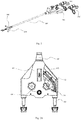
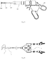
- FIG. 1 is a schematic structural view of an overall structure of a natural orifice translumenal minimally invasive surgical apparatus according to an embodiment of the disclosure.
- the natural orifice translumenal minimally invasive surgical apparatus comprises a control box assembly 300, a hose assembly 400 fixedly connected at a middle position at a distal or front end of the control box assembly 300, and a serpentine structure 500 and a tip assembly 600 provided within the hose assembly 400. Axes of the hose assembly 400, the serpentine structure 500 and the tip assembly 600 coincide with each other.
- the control box assembly 300 is connected with left and right surgical tools 100, 200 at a proximal or rear end thereof.
- the control box assembly 300 is a manipulation assembly of the natural orifice translumenal minimally invasive surgical apparatus.
- the control box assembly 300 may comprise a front sheath assembly 101 having a rear end fixedly connected with a front end of a control box housing 107.
- the front sheath assembly 101 provides passages for the surgical tools 100 and 200 and for a drive wire for control action of the control box assembly 300. Therefore, the front sheath assembly 101 has a predetermined rigidity, and thus plays an important connecting role.
- the front sheath assembly 101 has a front end sequentially connected with the serpentine structure 500 and the tip assembly 600 by the hose assembly 400.
- control box housing 107 may include a lower housing and an upper housing fixed onto the lower housing.
- a fixing plate 113 is fixed to the lower housing by a pin.
- Two tool tubes 114 with the same structure are fixed onto the fixing plate 113 by a pressing block 115 and arranged symmetrically in a left-and-right direction.
- a front end of each of the tool tubes 114 is disposed within the front sheath assembly 101 at thereof.
- the tool tube 114 serves as a passage for the surgical tool.
- Partition plates 112 may be fixed on the fixing plate 113 by a pin, and chutes 110 may be fixedly connected to the partition plate 112 by a pin, respectively.
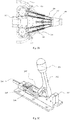
- control box assembly 300 may further comprise a triangulation drive assembly 102 connected between the partition plates 112.
- the triangulation drive assembly 102 includes a knob cap 201 operable by a surgeon to achieve movement of the tip assembly 600.
- the triangulation drive assembly 102 may comprise a toggle lever 202 passing through a middle portion of the upper housing.
- the knob cap 201 is connected to a top portion of the toggle lever 202 by a key.
- the knob cap 201 can serve as a manually operated object for pulling the toggle lever 202 back and forth.
- the toggle lever 202 is rotatably connected onto a holder 203 by a connection pin at a rear end of a bottom thereof so as to rotate about the connection pin.
- the toggle lever 202 is rotatably connected with a rear end of a pull rod 207 by a connection pin at a front end of the bottom thereof.
- the pull rod 207 is rotatably connected with a slider 204 by a pin at a front end thereof.
- the slider 204 is slidably connected with the holder 203 by a guide rail and slider structure, thereby rotation of the toggle lever 202 can be converted into a linear movement of the slider 204.
- the holder 203 is fixed onto the partition plate 112.
- a spring 205 is fixed to a front end of the slider 204 at a rear end thereof and is fixed on a front wall of the holder 203 at a front end thereof.
- the slider 204 has a sliding axis coincident with an axis of a guide rail of the holder 203.
- a linear transmission wire 117 has one end fixedly connected to one end of a triangulation wire joint 206 and the other end sequentially passing through the front sheath assembly 101, a guide wire hole in a connection ring 702 of the hose assembly 400 and the serpentine structure 500 and then connected to a rear end of a stretching wire 609 of the tip assembly 600.
- the spring 205 is normally extended such that the slider 204 is close to the toggle lever 202, and the slider 204 is normally kept away from a front wall of the holder 203.
- the spring 205 may be compressed by pressing the toggle lever 202 downwardly.
- the toggle lever 202 is returned to an original position by an elastic force of the spring 205.
- the holder 203 is formed with a cylindrical hole in the front wall thereof.
- a rear end of the triangulation wire joint 206 passes through the cylindrical hole and the spring 205 and is fixedly connected with the slider 204.
- the triangulation wire joint 206 has an axis coincident with the sliding axis of the slider 204.
- Manually pulling the toggle lever 202 will drive the pull rod 207 to be moved. Since the pull rod 207 is connected to one end of the slider 204, the linear movement of the slider 204 will drive the triangulation wire joint 206 to be moved.
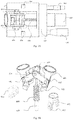
- the control box assembly 300 further comprises two rotary switches 104 disposed symmetrically in the left-and-right direction on a rear side of the partition plate 112 respectively and serving as transmission components of the minimally invasive surgery control box.
- the two rotary switches 104 have the same structure.
- Each rotary switch 104 includes a swinging rod 402, at a top of which a swinging wheel 401 is fixed, and a threaded bracket 403 formed with a center hole in a top wall thereof and a cavity communicating with the center hole in a middle portion thereof.
- the swinging rod 402 has a lower portion passing through the center hole of the threaded bracket 403 and extending into the cavity.
- the swinging rod 402 is engaged with the center hole of the threaded bracket 403 through a clearance fit.
- An externally-toothed gear 302 is fixed to a bottom portion of the swinging rod 402 located in the threaded bracket 403.
- An upper magnet assembly 408 is fixed to a bottom wall of the external gear 302.
- the threaded bracket 403 is fixed to a threaded seat 404 fixed onto the fixing plate 113 by a fixing bolt 405.
- An internally-geared ring 301 is fixed in the threaded bracket 403.
- a lower magnet assembly 409 is fixed to an inner wall of a bottom portion of the threaded seat 404 opposite to the upper magnet assembly 408.
- the externally-toothed gear 302 is supported on a thrust spring 407.
- the upper magnet assembly 408 is wrapped within the thrust spring 407.
- An upper end of the thrust spring 407 is in contact with a lower end of the externally-toothed gear 302 in a normal state, i.e., in a non-stressed state.
- the thrust spring 407 is fixedly connected with the lower magnet assembly 409 at a lower end thereof.
- a packing washer 406 is sleeved or fitted over the thrust spring 407 located at a lower portion of the internally-geared ring 301 to radially fix the thrust spring 407, thereby functioning as a limiting device.
- Axes of the internally-geared ring 301 and the externally-toothed gear 302 are coincident with the axis of the swinging rod 402.
- the swinging rod 402 is movable in an up-and-down direction to cause the internally-geared ring 301 to engage with or disengage from the externally-toothed gear 302.
- Sprockets 103 are mounted on the swinging rod 402 located at an upper part of the threaded bracket.
- the sprockets 103 include left and right sprockets 103 having the same structure.
- the thrust spring 407 is extended in the normal state, i.e., in the non-stressed state.
- the externally-toothed gear 302 is brought close to an upper end surface of an inner wall of the threaded bracket 403 by the extending force of the spring, so that the externally-toothed gear 302 is not engaged with the internally-geared ring 301.
- the swinging rod 402 is driven to be rotated so as to drive the externally-toothed gear 302 to be rotated.
- the externally-toothed gear 302 and the upper magnet assembly 408 move downwardly together with the swinging wheel 401.
- the upper magnet assembly 408 is attracted to the lower magnet assembly 409.
- the externally-toothed gear 302 and the internally-geared ring 301 are located in a same plane and thus engaged with each other, and friction contact of the internally-geared ring 301 with the externally-toothed gear 302 prevents the swing wheel from being rotated, thereby locking the control box assembly.
- the threaded bracket 403 can fix the swinging rod 402 to some extent in an axial direction.
- the swinging wheel 401 is manually pulled upwardly, the distance between the upper magnet assembly 408 and the lower magnet assembly 409 becomes larger and an attractive force between the magnet assemblies become smaller than the extending force of the thrust spring 407.
- the externally-toothed gear 302 is moved upwardly to be disengaged from the internally-geared ring 301 under the extending force of the thrust spring 407, thereby unlocking the surgical control box assembly.
- the swinging rod 402 then continues to move upwardly to restore to its initial state, and the externally-toothed gear 302 is in contact with the upper end of the thread bracket 403, thereby realizing a non-linear action switch.
- the surgical control box is unlocked.
- the swinging rod 402 is rotatable about its own axis, and the sprockets 103 key-fitted with the swinging rod 402 is rotated with rotation of the swinging rod 402.
- a set of chutes 110 are fixed to the partition plates 112 at a front side of each sprocket 103, respectively.
- Each set of chutes 110 includes two chutes 110 disposed at a predetermined interval.
- the sprocket 103 on each swinging rod 402 is engaged with a chain 111 surrounding the sprocket 103.
- Each of the chains 111 has two free ends disposed within the two chutes 110 of one set of the chutes 110, respectively.
- the chain 111 is driven by the swinging rod 402 to reciprocate linearly in the chutes 110.
- Both of the free ends of each of the chains 111 are connected with one end of each of four transmission wires 116, and the other end of each of the four transmission wires 116 sequentially passes through the front sheath assembly 101, the guide wire hole of the connection ring 702 and a guide wire hole of the serpentine structure 500, and is then fixed in an rear end opening of a tip body 607 of the tip assembly 600.
- the transmission wire 116 is slidable back and forth in the guide wire hole of the connection ring 702 so as to be tensioned and relaxed, so that the serpentine structure 500 is moved in a bended way by the pulling action of the transmission wire to achieve actions of the distal hose assembly 400, thereby allowing operating the front end of surgical apparatus to pitch and swing.
- the transmission wires 116 may be connected with the serpentine structure 500 by a known connection structure, and the transmission wire 116 may be slidable in the guide wire hole.
- the rotary switch 104 is manually operated to be rotated about its own axis so as to drive the sprockets 103 to be rotated together therewith, so that the chains 111 fixedly connected onto the sprockets 103 are moved linearly.
- the linear movement of the chains 111 drives the transmission wire 116 to slide in the guide wire hole, and the linear movement of the transmission wires 116 drives the serpentine structure 500 of the surgical apparatus to be moved, thereby achieving a desired surgical passage structure.
- the rotary switch 104 When the rotary switch 104 is pressed downwardly so that the internally-geared ring 301 is engaged with the externally-toothed gear 302, the rotary switch 104 can not be rotated, thereby locking the control box assembly. In this case, the transmission wire is kept in the tensioning state so that the distal surgical tool is in a position locking state. Referring to FIG.
- the rotary switch 104 is manually operated to drive the transmission wires 116 to be tensioned and moved linearly, which allows the distal serpentine structure 500 to be bent upwardly or downwardly and to swing in the left-and-right direction, thereby adjusting the placement of the surgical apparatus.
- the locking of the up-and-down pitch and left-and-right swinging positions of the distal snake-bone structure 500 is realized by the engagement state of the two sets of gears.
- the realization of the up-and-down pitch and left-and-right swinging movement may refer to a wire connection structure disclosed in CN200910306053.5 , thereby increasing the range of reachable surgical space of the surgical apparatus.
- the control box housing 107 is provided with two quick-change devices 105, which are arranged, as important components for performing a minimally invasive surgery, at left and right sides of a rear wall of the lower housing of the control box housing 107, respectively.
- the two quick-change devices 105 include two lower connection sleeves 501 fixedly connected on the left and right sides of the rear wall of the lower housing of the control box housing 107, respectively.
- Each of the lower connection sleeves 501 has a front end fixedly connected with the rear end of the tool tube 114 at the corresponding side.
- Each of the lower connection sleeves 501 is sleeved and fixed with an outer telescopic sleeve 502 having a center hole into which a middle telescopic sleeve 503 is slidably inserted.
- the middle telescopic sleeve 503 has a center hole into which an inner telescopic sleeve 504 is slidably inserted.
- An upper connection sleeve 506 is fixed to a rear end of the inner telescopic sleeve 504.
- the upper connection sleeve 506 is symmetrically formed with two rectangular slots of the same structure at either side along an axis thereof.
- Two unlocking bars 507 of the same structure each comprise a straight bar segment inserted into the rectangular slot at the corresponding side through a clearance fit.
- the straight bar segment has a rear end provided with a protruding hook hooked with a groove in the surgical tool. Further, the straight bar segment has a front end connected with a pressing plate.
- the bar segment of each unlocking bar 507 is rotatably connected with the upper connection sleeve 506 by a rotation shaft. A portion of the upper connection sleeve 506 opposite to the pressing plate is fixedly connected with a push rod 505 by a spring. When the unlocking bar 507 is rotated about the rotation shaft, the pressing plate may contact with a top portion of the push rod 505.
- the groove within the surgical tool is engaged with the hook of the unlocking bar 507 by frictionally pressing a front end of a bar end of the unlocking bar 507.
- the straight bar segment of the unlocking bar 507 at a front end thereof is pressed by a force against the pressing plate at a rear end of the unlocking bar 507 so as to be in contact with the push rod 505, so that the front end of the unlocking bar 507 is held in a fixed position, thereby securing the surgical tool.
- the pressing plate of the unlocking bar 507 is manually pressed to compress the spring sleeved or fitted over the push rod 505, thereby changing the cooperation relationship of the push rod 505 with the unlocking bar 507 of the quick-change device 105, so that the straight bar section of the unlocking bar 507 is deflected outwardly to disengage the hook on the front end of the unlocking bar 507 from the groove within the surgical tool, thereby disassembling the surgical tool for quickly replacing the surgical tool.
- an air-water switch 106 may be connected to the upper housing to facilitate the operation of the surgeon.
- the water-gas switch 106 is connected with a water pipe to access a water source.
- the water-vapor switch 106 may be turned on to clean a lens, so that the surgeon can perform the surgery with good visual field.
- the water-vapor switch 106 may be turned on to clean organ surface of the human body. During performing the surgery, there may be bleeding. In this case, the air-water switch 106 is activated to clean the organs to be subject to the surgery, which may improve security of the surgical operation.
- the air-water switch 106 may have the existing structure in the prior art.
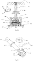
- the tip assembly 600 provides a support passage for an end effector of the minimally invasive surgical instrument.
- the tip assembly 600 enables connecting the end effector of the surgical tool with the hose assembly 400 of the surgical apparatus.
- the tip assembly 600 comprises a tip body 607 and an opening-closing body mounted in a middle groove of the tip body 607.
- the opening-closing body includes two triangulation rings 601 having the same structure and symmetrically arranged in the left-and-right direction.
- a triangulation pulling rod 610 is disposed at a middle position between the two triangulation rings 601.
- Each of the triangulation rings 601 is symmetrically provided with a cylindrical boss 612 and a cylindrical hole 613 at either sides thereof.
- the cylindrical boss 612 has an axis parallel to an axis of the cylindrical hole 613 and perpendicular to the axis of the triangulation ring 601.
- Each of the cylindrical bosses 612 is rotatably connected with one end of each of links 602 including two front links 602 at a front side of the triangulation pulling rod 610 and two rear links 602 at a rear side of the triangulation pulling rod.
- the other ends of the two front links 602 and the two rear links 602 are respectively rotatably connected to front and the rear ends of the triangulation pulling rod 610 by pins 611.
- a front end of a stretching wire 609 is vertically and fixedly connected onto the triangulation pulling rod 610.
- a triangulation spring 608 is sleeved or fitted over the stretching wire 609.
- a rear end of the stretching wire 609 passes through a middle opening of the tip body 607 in which a boss is arranged.
- the triangle spring 608 is disposed in the middle opening with a predetermined gap therebetween and is fixedly connected to the boss at a lower end thereof.
- an upper end of the triangulation spring 608 is in contact with a bottom end of the triangulation pulling rod 610, and each cylindrical hole 613 is rotatably connected with a cylindrical side of a triangulation pin 603 fixed onto the tip body 607, so that the triangulation ring 601 is rotatable about the triangulation pin 603.
- the triangulation pin 603 has a triangulation prism structure.
- the tip body 607 is formed with a triangulation prism hole 615 into which the triangulation prism structure is fixed.
- the tip body 607 is provided with arc grooves 614 in a middle slotted inner wall thereof corresponding to the four cylindrical bosses 612.
- An end portion of each cylindrical boss 612 of the triangulation rings 601 is slidably disposed in a corresponding one of the arc grooves 614.
- the cylindrical boss 612 is slidable back and forth in the arc groove 614.
- the triangulation pulling rod 610, the links 602, the triangulation pin 603 and the triangulation ring 601 are rotatably connected together to form a four-link mechanism.
- the stretching wire 609 is pulled to move linearly downwards so as to drive the triangulation pulling rod 610 to compress the triangulation spring 608 to move downwards.
- the link 602 rotatably connected to the triangulation pulling rod 610 is pulled to be rotated to drive the cylindrical boss 612 of the right triangulation ring 601 to slide in the arc groove 614 in the tip body 607, so that the triangulation ring 601 is correspondingly rotated outwardly about the triangulation pin 603.
- the rotation of the pulling rod 602 drives the left triangle ring 601 to be rotated outwardly, and thereby the two triangulation rings 601 are respectively rotated outwardly so that a larger angle is formed between the two triangulation rings 601, thereby realizing movement output of the triangulation rings 601 of the distal tip assembly 600 of the natural orifice translumenal surgical apparatus.
- a small angle ⁇ 1 is formed between the left and right triangulation rings 601.
- the triangulation drive assembly 102 is manually operated and the stretching wire 609 is tensioned to reach an attitude shown in FIG.
- the two surgical tools 100, 200 sequentially pass through the connection sleeves 506 at the corresponding sides, the tool tubes 114 of the control box at the corresponding sides, the front sheath assembly 101 of the surgical apparatus, the tool hole of the connection ring 702 of the hose assembly 400 and the serpentine structure 500, respectively.
- the rear ends of the two surgical tools 100 and 200 are fixed through the engagement of the groove with the hook of the unlocking bar 507, respectively.
- the distal end effector of each surgical tool passes through a surgical tool passageway 605 and is disposed within the triangulation ring 601 of the tip assembly 600 of the surgical apparatus at the corresponding side in a clearance fit manner, respectively.
- the end effector of each surgical tool is passively disposed in the triangulation ring 601 to be moved together with the triangulation ring 601 correspondingly.
- the hose assembly 400 provides a passageway for the minimally invasive surgical tool and the transmission wire.
- the hose assembly 400 is in direct contact with the natural orifice of the human body, thus has good softness without damage to the natural orifice of the human body.
- the hose assembly 400 comprises an outer fixing sheath 701 fixedly connected with the front sheath assembly 101 to form a unitary structure therewith.
- the outer fixing sheath 701 is a rubber tube and is sequentially connected with the connection ring 704 and an outer shell 703 at a front end thereof.
- Four connection rings 702 are fixedly arranged within the out fixing sheath 701 at a predetermined interval in a front-and-back direction thereof.
- Each of the connection rings 702 is provided with a plurality of cylindrical guide wire holes and two tool holes.
- the surgical tools 100 and 200 pass through the tool hole of the hose assembly 400.
- the serpentine structure 500 is installed within the outer shell 703.
- FIG. 6 is a schematic view of application of the natural orifice translumenal minimally invasive surgical apparatus according to an embodiment of the disclosure in a stomach surgical operation.
- the end effector of the surgical tool of the minimally invasive surgical apparatus 1 according to the embodiment of the disclosure illustrated in FIG. 6 is extended into a stomach 3 through an esophagus 2 of the human body to perform a surgical operation.
- the end effectors of the surgical tools 100, 200 are in direct contact with the stomach 3 of the human body.
- the hose assembly 400 of the surgical apparatus is in direct contact with the esophagus 2 of the human body.
- the natural orifice translumenal minimally invasive surgical apparatus is operated as follows.
- the minimally invasive surgical tool is held by the surgeon.
- the surgical apparatus is firstly placed properly by a surgeon.
- the control box assembly 300 is fixed in position.
- the different left and right rotary switches 104 are adjusted to control different actions, respectively.
- the left rotary switch 104 performs a pitch motion of the distal serpentine structure 500 of the surgical apparatus, and the right rotary switch 104 swings the serpentine structure 500 in the left-and-right direction.
- the surgeon faces the control box assembly 300, which is normally in an unlocked state, rotates the left rotary switch 104 counterclockwise to pitch upwardly the distal serpentine structure 500, and presses the rotary switch 104 downwardly to lock the surgical control box assembly 300.
- the distal serpentine structure 500 of the surgical apparatus is maintained in an upward pitching state. If the rotary switch 104 is pulled upwardly, the control box assembly 300 is unlocked. When the left rotary switch 104 is rotated clockwise, the distal serpentine structure 500 is pitched downwardly. When the control box assembly 300 is in the unlocked state under the normal condition, the right rotary switch 104 is rotated counterclockwise to swing the distal snake-bone structure 500 leftwards. Then, the rotary switch 104 is depressed downwardly to lock the surgical control box assembly 300. At this time, the distal serpentine structure 500 of the surgical apparatus is maintained in a leftward swinging state. If the rotary switch 104 is pulled upwardly, the control box assembly 300 is unlocked.
- the right rotary switch 104 is rotated clockwise to swing the snake-bone structure 500 rightwards.
- the rotary switch 104 is depressed downwardly to lock the control box assembly 300.
- the distal serpentine structure 500 of the surgical apparatus is maintained in the current state.
- the surgical tool is inserted into the passageway of the upper connection sleeve 506 of the quick-change device 105 of the control box assembly 300, and the surgical tool presses the straight bar section of the unlocking bar 507 by friction, so that the groove in the surgical tool is engaged with the hook of the unlocking bar 507, such that the end effector of the surgical tool sequentially passes through the tool tube 114 of the control box, the front sheath assembly 101, the hose assembly 400 and the serpentine structure 500 of the surgical apparatus.
- the end effector of the surgical tool is arranged at the tip assembly 600 of the surgical apparatus with an operating handle end of the surgical tool being connected with the quick-change device 105 of the control box through the groove-hook engagement, so that the operating end of the surgical tool is positioned at the quick-change device 105 at the rear end of the control box and the end effector is disposed at the tip assembly 600 of the surgical apparatus, thereby fixing the surgical tool.
- the triangle drive assembly 102 is adjusted by manually pulling the toggle rod 202 rearwards to linearly pull the transmission wire so as to drive the stretching wire 609 to be moved, thereby opening the triangulation rings 102 on the tip assembly outwards, thus realizing movement output of the triangulation ring 601 of the tip assembly 600 at the front end of the natural orifice surgical translumenal apparatus.
- a larger angle is formed between the two triangle rings 601 to change the position of the end effector of the surgical tool so that the end effector is as close as possible to the lesion tissue to form a better operating triangle region.
- the air-water switch 106 then is turned on for preparing to clean the organs. At this time, the surgical apparatus is ready, and the surgeon then can start minimally invasive surgery.
- an object of the disclosure is to provide a natural orifice translumenal minimally invasive surgical apparatus, which is small in volume, convenient to use, flexible in operation and has a large triangulation region in surgical operation.
Landscapes
- Health & Medical Sciences (AREA)
- Surgery (AREA)
- Life Sciences & Earth Sciences (AREA)
- Engineering & Computer Science (AREA)
- Heart & Thoracic Surgery (AREA)
- Nuclear Medicine, Radiotherapy & Molecular Imaging (AREA)
- Biomedical Technology (AREA)
- Medical Informatics (AREA)
- Molecular Biology (AREA)
- Animal Behavior & Ethology (AREA)
- General Health & Medical Sciences (AREA)
- Public Health (AREA)
- Veterinary Medicine (AREA)
- General Engineering & Computer Science (AREA)
- Pathology (AREA)
- Mechanical Engineering (AREA)
- Surgical Instruments (AREA)
Claims (6)
- Appareil chirurgical minimalement invasif transluminal pour orifice naturel comprenant un ensemble de boîte de commande (300), un ensemble de tuyau flexible (400), une structure de serpentin (500) et un ensemble de pointe (600), dans lequel :l'ensemble de boîte de commande (300) est raccordé de manière séquentielle et fixe avec l'ensemble de tuyau flexible (400), la structure de serpentin (500) et l'ensemble de pointe (600) dans une partie centrale de son extrémité distale ;l'ensemble de boîte de commande (300) étant caractérisé en ce qu'il comprend en outre :un boîtier de boîte de commande (107) ayant une paroi arrière prévue avec un dispositif à changement rapide (105) au niveau de chacun de ses côtés, le dispositif à changement rapide (105) comprenant un manchon de raccordement supérieur (506) dans lequel un instrument chirurgical (100, 200) est inséré ; etun ensemble d'entraînement de triangulation (102) comprenant un capuchon de bouton (201) opérationnel pour déplacer l'ensemble de pointe (600) au niveau de l'extrémité distale ; etl'ensemble de tuyau flexible (400) comprend une gaine de fixation externe (701) ayant une extrémité avant raccordée avec une gaine externe (703) dans laquelle la structure de serpentin (500) est montée,l'ensemble de pointe (600) comprend un corps de pointe (607) et un corps d'ouverture - fermeture monté dans une rainure centrale du corps de pointe (607) ;le corps d'ouverture - fermeture comprend deux bagues de triangulation (601, 601) ayant la même structure et agencées de manière symétrique dans une direction gauche et droite, et une tige de traction de triangulation (610) est disposée au niveau d'une partie centrale entre les deux bagues de triangulation (601, 601) ;chacune des bagues de triangulation (601) est prévue de manière symétrique avec un bossage cylindrique (612) et un trou cylindrique au niveau de chacun de ses côtés, dans lequel le bossage cylindrique (612) a un axe parallèle à un axe du trou cylindrique et perpendiculaire à un axe de la bague de triangulation (601), et chacun des bossages cylindriques (612) est raccordé en rotation avec une extrémité de chacune des liaisons (602) comprenant deux liaisons avant (602, 602) et deux liaisons arrière (602, 602), et les autres extrémités des deux liaisons avant (602, 602) et des deux liaisons arrière (602, 602) sont raccordées respectivement en rotation aux extrémités avant et arrière de la tige de traction de triangulation (610) par des broches ;une extrémité avant d'un fil extensible (609) est raccordée verticalement et de manière fixe sur la tige de traction de triangulation (601), un ressort de triangulation (608) est emmanché sur le fil extensible (609), et une extrémité arrière du fil extensible (609) passe par une ouverture centrale du corps de pointe (607) dans laquelle un bossage est agencé ;le ressort de triangulation (608) est disposé dans l'ouverture centrale avec un espace prédéterminé entre eux et est raccordé de manière fixe au bossage au niveau de son extrémité inférieure, dans lequel dans un état dans lequel les axes des deux bagues de triangulation (601) sont parallèles entre elles, une extrémité supérieure du ressort de triangulation (608) est en contact avec une extrémité inférieure de la tige de traction de triangulation (601), et chaque trou cylindrique est raccordé en rotation avec un côté cylindrique d'une broche de triangulation (603) fixée sur le corps de pointe (607), de sorte que la bague de triangulation (601) peut tourner autour de la broche de triangulation (603) ; etle corps de pointe (607) est prévu avec des rainures arquées (614) dans sa paroi interne fendue centrale correspondant aux quatre bossages cylindriques (612), et une partie d'extrémité de chaque bossage cylindrique (612) des bagues de triangulation (601) est disposée de manière coulissante dans une rainure correspondante des rainures arquées (614), le bossage cylindrique (612) peut coulisser vers l'arrière et vers l'avant dans la rainure arquée (614), et la tige de traction de triangulation (601), les liaisons, la broche de triangulation (603) et la bague de triangulation (601) sont raccordées en rotation ensemble afin de former un mécanisme à quatre liaisons.
- Appareil selon la revendication 1, dans lequel :l'ensemble d'entraînement de triangulation (102) comprend un levier à genouillère (202) passant par une partie centrale d'un boîtier supérieur de l'ensemble de boîte de commande (300) ;le levier à genouillère (202) est raccordé avec le capuchon de bouton (201) par une clé au niveau de sa partie supérieure, raccordé en rotation sur un support (203) par une broche de raccordement au niveau d'une extrémité arrière de sa partie inférieure, et raccordé en rotation avec une extrémité arrière d'une tige de traction (207) par une broche de raccordement au niveau d'une extrémité avant de sa partie inférieure, la tige de traction (207) étant raccordée en rotation avec une glissière (204) par une broche au niveau de son extrémité avant ;la glissière (204) est raccordée, de manière coulissante, avec le support (203) par un rail de guidage et une structure de glissière, le support (203) est fixé sur une plaque de séparation (112) de l'ensemble de boîte de commande (300), un ressort (205) est fixé sur une extrémité avant de la glissière (204) au niveau de son extrémité arrière et est fixé sur une paroi avant du support (203) au niveau de son extrémité avant, et la glissière (204) a un axe de coulissement qui coïncide avec un axe d'un rail de guidage du support (203) ; etl'appareil comprend en outre un fil de transmission linéaire (117) ayant une extrémité raccordée de manière fixe à une extrémité du joint de fil de triangulation (206) et l'autre extrémité passant, de manière séquentielle, par un ensemble de gaine distale (101) de l'ensemble de boîte de commande (300), l'ensemble de tuyau flexible (400) et la structure de serpentin (500) et ensuite raccordée à une extrémité arrière d'un fil de transmission de l'ensemble de pointe (600).
- Appareil selon la revendication 1, dans lequel :l'ensemble de boîte de commande (300) comprend en outre deux commutateurs rotatifs (104, 104) ; chacun des commutateurs rotatifs (104, 104) comprend une tige oscillante (402), au niveau d'une partie supérieure de laquelle une roue oscillante (401) est fixée, et une console filetée (403) formée avec un trou central dans sa paroi supérieure et une cavité communiquant avec le trou central dans sa partie centrale ;la tige oscillante (402) a une partie inférieure passant par le trou central de la console filetée (403) et s'étendant dans la cavité, et est mise en prise avec le trou central de la console filetée (403) par un ajustement avec jeu ; etun engrenage extérieurement denté (302) est fixé sur une partie inférieure de la tige oscillante (402) positionnée dans la console filetée (403), et un ensemble d'aimant supérieur (408) est fixé sur une paroi inférieure de l'engrenage extérieurement denté (302),la console filetée (403) est fixée sur un siège fileté (404) qui est fixé sur une plaque de fixation (113) par un boulon de fixation (405) ;une bague à denture intérieure (301) est fixée sur la console filetée (403) ;un ensemble d'aimant inférieur (409) est fixé dans une paroi interne d'une partie inférieure du siège fileté (404) dans une position opposée à l'ensemble d'aimant supérieur (408) ; l'engrenage extérieurement denté (302) est supporté sur un ressort de butée (407) ;l'ensemble d'aimant supérieur (408) est enroulé dans le ressort de butée (407),le ressort de butée (407) a une extrémité supérieure en contact avec une extrémité inférieure de l'engrenage extérieurement denté (302) dans son état non tendu et une extrémité inférieure raccordée de manière fixe avec l'ensemble d'aimant inférieur (409) ;une rondelle de garniture (406) est emmanchée sur le ressort de butée (407) positionné au niveau d'une partie inférieure de la bague à denture intérieure (301) pour fixer de manière radiale le ressort de butée (407) ;les axes de la bague à denture intérieure (301) et de l'engrenage extérieurement denté (302) coïncident avec un axe de la tige oscillante (402) et la tige oscillante (402) est mobile dans une direction ascendante et descendante pour amener la bague à denture intérieure (301) à se mettre en prise avec ou se dégager de l'engrenage extérieurement denté (302) ; etdes pignons (103) sont montés sur la tige oscillante (402) positionnée au niveau d'une partie supérieure de la console filetée (403).
- Appareil selon la revendication 3, dans lequel :un ensemble de goulottes (110, 110) sont fixées sur la plaque de séparation (112) au niveau d'un côté avant de chacun des pignons (103), respectivement ;chaque ensemble de goulottes (110) comprend deux goulottes (110, 110) disposées à un intervalle prédéterminé et le pignon (103) sur chaque tige oscillante (402) est mis en prise avec une chaîne (111) entourant le pignon ;chacune des chaînes (111) a deux extrémités libres disposées à l'intérieur des deux goulottes (110, 110) d'un ensemble des goulottes, respectivement, et la chaîne (111) peut être entraînée par la tige oscillante (402) pour effectuer un mouvement de va-et-vient linéaire dans la goulotte (111) ; etles deux extrémités libres de chaque chaîne (111) sont raccordées avec une extrémité des quatre fils de transmission (116), et l'autre extrémité de chacun des quatre fils de transmission (116) passe de manière séquentielle par l'ensemble de gaine distale (101), un trou de fil de guidage d'une bague de raccordement (702) de l'ensemble de tuyau flexible (400) et un trou de fil de guidage de la structure de serpentin (500) et est ensuite fixé dans une ouverture d'extrémité arrière d'un corps de pointe (607) de l'ensemble de pointe (600).
- Appareil selon la revendication 1, dans lequel :les deux dispositifs à changement rapide (105, 105) comprennent deux manchons de raccordement inférieurs (501) raccordés de manière fixe sur les côtés gauche et droit d'une paroi arrière d'un boîtier inférieur du boîtier de boîte de commande (107), respectivement ;chacun des manchons de raccordement inférieurs (501) a une extrémité avant raccordée de manière fixe avec une extrémité arrière du tube d'outil au niveau d'un côté correspondant ;chacun des manchons de raccordement inférieurs (501) est emmanché avec et fixé sur un manchon télescopique externe (502) ayant un trou central dans lequel un manchon télescopique central (503) est inséré de manière coulissante, et le manchon télescopique central (503) a un trou central dans lequel un manchon télescopique interne (504) est inséré de manière coulissante ;un manchon de raccordement supérieur (506) est fixé sur une extrémité arrière du manchon télescopique interne (504) et est formé de manière symétrique avec deux fentes rectangulaires de la même structure de chaque côté le long de son axe, et deux barres de déverrouillage (507) de la même structure comprennent chacune un segment de barre droit inséré dans la fente rectangulaire au niveau d'un côté correspondant par le biais d'un ajustement avec jeu ;le segment de barre droit à une extrémité arrière prévue avec un crochet en saillie accroché avec une rainure dans l'instrument chirurgical (100, 200) et une extrémité avant raccordée avec une plaque de pression et le segment de barre de chaque barre de déverrouillage (507) est raccordé de manière rotative avec le manchon de raccordement supérieur (506) par un arbre de rotation ; etle manchon de raccordement supérieur (506) a une partie opposée à la plaque de pression et raccordée de manière fixe à une tige de poussée (505) par un ressort, dans lequel la plaque de pression est autorisée à être en contact avec une partie supérieure de la tige de poussée (505) lorsque la barre de déverrouillage (507) tourne autour de l'arbre de rotation.
- Appareil selon la revendication 1, comprenant en outre un commutateur eau-air raccordé sur le boîtier supérieur.
Applications Claiming Priority (2)
| Application Number | Priority Date | Filing Date | Title |
|---|---|---|---|
| CN201610751855.7A CN106264626B (zh) | 2016-08-27 | 2016-08-27 | 一种基于自然腔道的微创手术装置 |
| PCT/CN2017/087729 WO2018040662A1 (fr) | 2016-08-27 | 2017-06-09 | Dispositif microchirurgical à base de canal naturel |
Publications (3)
| Publication Number | Publication Date |
|---|---|
| EP3345552A1 EP3345552A1 (fr) | 2018-07-11 |
| EP3345552A4 EP3345552A4 (fr) | 2019-04-24 |
| EP3345552B1 true EP3345552B1 (fr) | 2020-05-13 |
Family
ID=57674169
Family Applications (1)
| Application Number | Title | Priority Date | Filing Date |
|---|---|---|---|
| EP17844969.0A Active EP3345552B1 (fr) | 2016-08-27 | 2017-06-09 | Dispositif microchirurgical à base de canal naturel |
Country Status (4)
| Country | Link |
|---|---|
| US (1) | US10702253B2 (fr) |
| EP (1) | EP3345552B1 (fr) |
| CN (1) | CN106264626B (fr) |
| WO (1) | WO2018040662A1 (fr) |
Families Citing this family (21)
| Publication number | Priority date | Publication date | Assignee | Title |
|---|---|---|---|---|
| CN106264626B (zh) * | 2016-08-27 | 2018-07-24 | 天津大学 | 一种基于自然腔道的微创手术装置 |
| CN114403987B (zh) * | 2018-04-09 | 2024-12-03 | 李俊龙 | 一种腹腔镜用多功能手术抓钳及抓钳更换方法 |
| CN110584788A (zh) * | 2019-10-14 | 2019-12-20 | 山东建筑大学 | 一种四自由度微创手术器械驱动平台 |
| CN112426224B (zh) * | 2020-10-20 | 2022-01-28 | 郑州郅隆智能科技有限公司 | 一种毫米级超自由度精准智能微创设备及系统 |
| CN114366191B (zh) * | 2020-11-26 | 2025-09-12 | 中国人民解放军空军军医大学 | 可调式普胸外科手术用开胸器 |
| CN112244967B (zh) * | 2020-11-30 | 2021-08-03 | 武孟孟 | 一种一次性甲状腺穿刺器定位装置 |
| CN112704524B (zh) * | 2020-12-23 | 2022-07-15 | 王冬 | 一种用于食管与肠道缝合的空肠固定和移动装置 |
| CN113317849B (zh) * | 2021-04-22 | 2022-09-27 | 卫飞 | 一种骨穿刺针发射装置 |
| CN113425343B (zh) * | 2021-07-02 | 2022-10-04 | 西安交通大学医学院第一附属医院 | 一种神经内镜立体定向手术辅助通道设备 |
| CN113476144B (zh) * | 2021-08-23 | 2022-08-05 | 上海生知医疗科技有限公司 | 一种多自由度的便携微创手术机械臂 |
| CN114533271B (zh) * | 2021-09-13 | 2023-10-31 | 广西大学 | 一种单孔微创手术操控系统 |
| CN114668432B (zh) * | 2022-03-29 | 2024-06-07 | 吉林大学 | 一种经自然腔道诊疗一体式手术机器人 |
| CN114469283B (zh) * | 2022-03-31 | 2022-07-01 | 真健康(北京)医疗科技有限公司 | 连杆式四自由度穿刺针定位导向装置 |
| CN114869376B (zh) * | 2022-05-09 | 2023-03-10 | 南京鼓楼医院 | 一种胸腔镜下心房缝合器 |
| CN115059856B (zh) * | 2022-06-15 | 2024-01-12 | 郑州郑房测绘有限责任公司 | 一种适用于野外作业的地籍测绘用全站仪 |
| CN115089266A (zh) * | 2022-06-27 | 2022-09-23 | 张旭光 | 一种带蛇形管机构的手术钳 |
| CN115737067A (zh) * | 2022-11-09 | 2023-03-07 | 上海医疗器械(集团)有限公司手术器械厂 | 应用于可变形腔镜下的荷包成形钳装置 |
| CN115530726A (zh) * | 2022-11-11 | 2022-12-30 | 苏州阿酷育医疗科技有限公司 | 一种腔镜手术组件 |
| CN116269655B (zh) * | 2022-11-30 | 2025-08-26 | 邦尼医疗科技(常州)有限公司 | 手术器械终端工具双向差动装置 |
| CN116211392A (zh) * | 2023-01-20 | 2023-06-06 | 骨圣元化机器人(深圳)有限公司 | 骨锉转接装置及医疗设备 |
| CN116327280B (zh) * | 2023-04-26 | 2025-09-05 | 武汉米隽医疗器械有限公司 | 一种手术用拉钩 |
Family Cites Families (17)
| Publication number | Priority date | Publication date | Assignee | Title |
|---|---|---|---|---|
| JP3610110B2 (ja) * | 1995-02-23 | 2005-01-12 | オリンパス株式会社 | 医療用マニピュレータ |
| US5860995A (en) * | 1995-09-22 | 1999-01-19 | Misener Medical Co. Inc. | Laparoscopic endoscopic surgical instrument |
| US6352503B1 (en) * | 1998-07-17 | 2002-03-05 | Olympus Optical Co., Ltd. | Endoscopic surgery apparatus |
| US8518024B2 (en) * | 2006-04-24 | 2013-08-27 | Transenterix, Inc. | System and method for multi-instrument surgical access using a single access port |
| US8715270B2 (en) * | 2006-12-01 | 2014-05-06 | Boston Scientific Scimed, Inc. | Multi-part instrument systems and methods |
| US8591399B2 (en) | 2007-04-25 | 2013-11-26 | Karl Storz Endovision, Inc. | Surgical method utilizing transluminal endoscope and instruments |
| FR2934486B1 (fr) | 2008-07-29 | 2012-08-17 | Univ Joseph Fourier Grenoble I | Outil chirurgical modulaire |
| US20110230723A1 (en) | 2008-12-29 | 2011-09-22 | Salvatore Castro | Active Instrument Port System for Minimally-Invasive Surgical Procedures |
| US20100286478A1 (en) * | 2009-04-23 | 2010-11-11 | Usgi Medical, Inc. | Flexible surgery access systems |
| CN101637402B (zh) * | 2009-10-23 | 2011-05-18 | 天津大学 | 一种微创外科丝传动、四自由度手术工具 |
| CN102309363B (zh) * | 2010-06-29 | 2015-09-09 | 王东 | 一种综合内窥镜手术平台 |
| CN103110455B (zh) | 2012-12-18 | 2015-04-22 | 杭州好克光电仪器有限公司 | 一种输尿管镜 |
| US9797486B2 (en) | 2013-06-20 | 2017-10-24 | Covidien Lp | Adapter direct drive with manual retraction, lockout and connection mechanisms |
| US10258363B2 (en) * | 2014-04-22 | 2019-04-16 | Ethicon Llc | Method of operating an articulating ultrasonic surgical instrument |
| CN105796138B (zh) * | 2016-05-11 | 2018-04-10 | 天津大学 | 基于自然腔道的柔性微创手术器械 |
| CN106361383B (zh) | 2016-08-27 | 2018-09-25 | 天津大学 | 一种具有锁紧功能的自然腔道微创手术控制器 |
| CN106264626B (zh) * | 2016-08-27 | 2018-07-24 | 天津大学 | 一种基于自然腔道的微创手术装置 |
-
2016
- 2016-08-27 CN CN201610751855.7A patent/CN106264626B/zh active Active
-
2017
- 2017-06-09 WO PCT/CN2017/087729 patent/WO2018040662A1/fr not_active Ceased
- 2017-06-09 EP EP17844969.0A patent/EP3345552B1/fr active Active
- 2017-06-09 US US15/765,929 patent/US10702253B2/en active Active
Non-Patent Citations (1)
| Title |
|---|
| None * |
Also Published As
| Publication number | Publication date |
|---|---|
| WO2018040662A1 (fr) | 2018-03-08 |
| EP3345552A1 (fr) | 2018-07-11 |
| US20180280010A1 (en) | 2018-10-04 |
| EP3345552A4 (fr) | 2019-04-24 |
| CN106264626A (zh) | 2017-01-04 |
| US10702253B2 (en) | 2020-07-07 |
| CN106264626B (zh) | 2018-07-24 |
Similar Documents
| Publication | Publication Date | Title |
|---|---|---|
| EP3345552B1 (fr) | Dispositif microchirurgical à base de canal naturel | |
| JP6082553B2 (ja) | ブレーキ解除機構及びこれを備えた医療用マニピュレータ | |
| US10383647B2 (en) | Medical manipulator | |
| US10016187B2 (en) | Articulating surgical instruments and method of deploying the same | |
| KR101075294B1 (ko) | 최소 침습 수술 기구 | |
| JP6042678B2 (ja) | ブレーキ機構及びこれを備えた医療用マニピュレータ | |
| US20160113732A1 (en) | Surgical tool | |
| JP2010527690A (ja) | 外科用機器 | |
| JP6858954B2 (ja) | 内視鏡システム | |
| JP2015080556A (ja) | 高機能手術デバイス | |
| KR101241811B1 (ko) | 수술용 인스트루먼트 | |
| CN106361383B (zh) | 一种具有锁紧功能的自然腔道微创手术控制器 | |
| KR20120007107A (ko) | 멀티 방향 리트랙터 | |
| JP3215550U (ja) | 気管支鏡の引張コードのための制御機構 | |
| JP2013215507A (ja) | 医療用マニピュレータ | |
| CN108685604A (zh) | 微创手术器械 | |
| JP6053102B2 (ja) | 医療用マニピュレータ | |
| CN221813878U (zh) | 可解锁的内窥镜角度自锁机构 | |
| JP5909142B2 (ja) | 医療用マニピュレータ | |
| JP5990024B2 (ja) | 医療用マニピュレータ | |
| KR101861587B1 (ko) | 조작의 편의 및 위치 제어의 정확도와 견고함을 겸한 부인과 진료용 질경 | |
| JP2002291765A (ja) | 外科用処置具用の保持具 | |
| CN109925060A (zh) | 一种仿生手术器械及其控制方法 | |
| JP2013128667A (ja) | 角度固定具 | |
| KR20220161998A (ko) | 그립감이 향상된 수술용 포셉장치 |
Legal Events
| Date | Code | Title | Description |
|---|---|---|---|
| STAA | Information on the status of an ep patent application or granted ep patent |
Free format text: STATUS: THE INTERNATIONAL PUBLICATION HAS BEEN MADE |
|
| PUAI | Public reference made under article 153(3) epc to a published international application that has entered the european phase |
Free format text: ORIGINAL CODE: 0009012 |
|
| STAA | Information on the status of an ep patent application or granted ep patent |
Free format text: STATUS: REQUEST FOR EXAMINATION WAS MADE |
|
| 17P | Request for examination filed |
Effective date: 20180404 |
|
| AK | Designated contracting states |
Kind code of ref document: A1 Designated state(s): AL AT BE BG CH CY CZ DE DK EE ES FI FR GB GR HR HU IE IS IT LI LT LU LV MC MK MT NL NO PL PT RO RS SE SI SK SM TR |
|
| AX | Request for extension of the european patent |
Extension state: BA ME |
|
| RIC1 | Information provided on ipc code assigned before grant |
Ipc: A61B 17/34 20060101ALI20181001BHEP Ipc: A61B 17/29 20060101AFI20181001BHEP |
|
| REG | Reference to a national code |
Ref country code: DE Ref legal event code: R079 Ref document number: 602017016879 Country of ref document: DE Free format text: PREVIOUS MAIN CLASS: A61B0017000000 Ipc: A61B0017290000 |
|
| A4 | Supplementary search report drawn up and despatched |
Effective date: 20190321 |
|
| RIC1 | Information provided on ipc code assigned before grant |
Ipc: A61B 17/34 20060101ALI20190315BHEP Ipc: A61B 17/29 20060101AFI20190315BHEP |
|
| DAV | Request for validation of the european patent (deleted) | ||
| GRAP | Despatch of communication of intention to grant a patent |
Free format text: ORIGINAL CODE: EPIDOSNIGR1 |
|
| STAA | Information on the status of an ep patent application or granted ep patent |
Free format text: STATUS: GRANT OF PATENT IS INTENDED |
|
| INTG | Intention to grant announced |
Effective date: 20200217 |
|
| GRAS | Grant fee paid |
Free format text: ORIGINAL CODE: EPIDOSNIGR3 |
|
| GRAA | (expected) grant |
Free format text: ORIGINAL CODE: 0009210 |
|
| STAA | Information on the status of an ep patent application or granted ep patent |
Free format text: STATUS: THE PATENT HAS BEEN GRANTED |
|
| RAP1 | Party data changed (applicant data changed or rights of an application transferred) |
Owner name: TIANJIN UNIVERSITY |
|
| AK | Designated contracting states |
Kind code of ref document: B1 Designated state(s): AL AT BE BG CH CY CZ DE DK EE ES FI FR GB GR HR HU IE IS IT LI LT LU LV MC MK MT NL NO PL PT RO RS SE SI SK SM TR |
|
| AX | Request for extension of the european patent |
Extension state: BA ME |
|
| REG | Reference to a national code |
Ref country code: GB Ref legal event code: FG4D |
|
| REG | Reference to a national code |
Ref country code: CH Ref legal event code: EP |
|
| REG | Reference to a national code |
Ref country code: DE Ref legal event code: R096 Ref document number: 602017016879 Country of ref document: DE |
|
| REG | Reference to a national code |
Ref country code: AT Ref legal event code: REF Ref document number: 1269215 Country of ref document: AT Kind code of ref document: T Effective date: 20200615 |
|
| REG | Reference to a national code |
Ref country code: LT Ref legal event code: MG4D |
|
| REG | Reference to a national code |
Ref country code: NL Ref legal event code: MP Effective date: 20200513 |
|
| PG25 | Lapsed in a contracting state [announced via postgrant information from national office to epo] |
Ref country code: NO Free format text: LAPSE BECAUSE OF FAILURE TO SUBMIT A TRANSLATION OF THE DESCRIPTION OR TO PAY THE FEE WITHIN THE PRESCRIBED TIME-LIMIT Effective date: 20200813 Ref country code: GR Free format text: LAPSE BECAUSE OF FAILURE TO SUBMIT A TRANSLATION OF THE DESCRIPTION OR TO PAY THE FEE WITHIN THE PRESCRIBED TIME-LIMIT Effective date: 20200814 Ref country code: FI Free format text: LAPSE BECAUSE OF FAILURE TO SUBMIT A TRANSLATION OF THE DESCRIPTION OR TO PAY THE FEE WITHIN THE PRESCRIBED TIME-LIMIT Effective date: 20200513 Ref country code: LT Free format text: LAPSE BECAUSE OF FAILURE TO SUBMIT A TRANSLATION OF THE DESCRIPTION OR TO PAY THE FEE WITHIN THE PRESCRIBED TIME-LIMIT Effective date: 20200513 Ref country code: PT Free format text: LAPSE BECAUSE OF FAILURE TO SUBMIT A TRANSLATION OF THE DESCRIPTION OR TO PAY THE FEE WITHIN THE PRESCRIBED TIME-LIMIT Effective date: 20200914 Ref country code: IS Free format text: LAPSE BECAUSE OF FAILURE TO SUBMIT A TRANSLATION OF THE DESCRIPTION OR TO PAY THE FEE WITHIN THE PRESCRIBED TIME-LIMIT Effective date: 20200913 Ref country code: SE Free format text: LAPSE BECAUSE OF FAILURE TO SUBMIT A TRANSLATION OF THE DESCRIPTION OR TO PAY THE FEE WITHIN THE PRESCRIBED TIME-LIMIT Effective date: 20200513 |
|
| PG25 | Lapsed in a contracting state [announced via postgrant information from national office to epo] |
Ref country code: RS Free format text: LAPSE BECAUSE OF FAILURE TO SUBMIT A TRANSLATION OF THE DESCRIPTION OR TO PAY THE FEE WITHIN THE PRESCRIBED TIME-LIMIT Effective date: 20200513 Ref country code: HR Free format text: LAPSE BECAUSE OF FAILURE TO SUBMIT A TRANSLATION OF THE DESCRIPTION OR TO PAY THE FEE WITHIN THE PRESCRIBED TIME-LIMIT Effective date: 20200513 Ref country code: LV Free format text: LAPSE BECAUSE OF FAILURE TO SUBMIT A TRANSLATION OF THE DESCRIPTION OR TO PAY THE FEE WITHIN THE PRESCRIBED TIME-LIMIT Effective date: 20200513 Ref country code: BG Free format text: LAPSE BECAUSE OF FAILURE TO SUBMIT A TRANSLATION OF THE DESCRIPTION OR TO PAY THE FEE WITHIN THE PRESCRIBED TIME-LIMIT Effective date: 20200813 |
|
| REG | Reference to a national code |
Ref country code: AT Ref legal event code: MK05 Ref document number: 1269215 Country of ref document: AT Kind code of ref document: T Effective date: 20200513 |
|
| PG25 | Lapsed in a contracting state [announced via postgrant information from national office to epo] |
Ref country code: AL Free format text: LAPSE BECAUSE OF FAILURE TO SUBMIT A TRANSLATION OF THE DESCRIPTION OR TO PAY THE FEE WITHIN THE PRESCRIBED TIME-LIMIT Effective date: 20200513 Ref country code: NL Free format text: LAPSE BECAUSE OF FAILURE TO SUBMIT A TRANSLATION OF THE DESCRIPTION OR TO PAY THE FEE WITHIN THE PRESCRIBED TIME-LIMIT Effective date: 20200513 |
|
| PG25 | Lapsed in a contracting state [announced via postgrant information from national office to epo] |
Ref country code: AT Free format text: LAPSE BECAUSE OF FAILURE TO SUBMIT A TRANSLATION OF THE DESCRIPTION OR TO PAY THE FEE WITHIN THE PRESCRIBED TIME-LIMIT Effective date: 20200513 Ref country code: CZ Free format text: LAPSE BECAUSE OF FAILURE TO SUBMIT A TRANSLATION OF THE DESCRIPTION OR TO PAY THE FEE WITHIN THE PRESCRIBED TIME-LIMIT Effective date: 20200513 Ref country code: RO Free format text: LAPSE BECAUSE OF FAILURE TO SUBMIT A TRANSLATION OF THE DESCRIPTION OR TO PAY THE FEE WITHIN THE PRESCRIBED TIME-LIMIT Effective date: 20200513 Ref country code: ES Free format text: LAPSE BECAUSE OF FAILURE TO SUBMIT A TRANSLATION OF THE DESCRIPTION OR TO PAY THE FEE WITHIN THE PRESCRIBED TIME-LIMIT Effective date: 20200513 Ref country code: EE Free format text: LAPSE BECAUSE OF FAILURE TO SUBMIT A TRANSLATION OF THE DESCRIPTION OR TO PAY THE FEE WITHIN THE PRESCRIBED TIME-LIMIT Effective date: 20200513 Ref country code: SM Free format text: LAPSE BECAUSE OF FAILURE TO SUBMIT A TRANSLATION OF THE DESCRIPTION OR TO PAY THE FEE WITHIN THE PRESCRIBED TIME-LIMIT Effective date: 20200513 Ref country code: DK Free format text: LAPSE BECAUSE OF FAILURE TO SUBMIT A TRANSLATION OF THE DESCRIPTION OR TO PAY THE FEE WITHIN THE PRESCRIBED TIME-LIMIT Effective date: 20200513 Ref country code: IT Free format text: LAPSE BECAUSE OF FAILURE TO SUBMIT A TRANSLATION OF THE DESCRIPTION OR TO PAY THE FEE WITHIN THE PRESCRIBED TIME-LIMIT Effective date: 20200513 |
|
| REG | Reference to a national code |
Ref country code: CH Ref legal event code: PL |
|
| REG | Reference to a national code |
Ref country code: DE Ref legal event code: R097 Ref document number: 602017016879 Country of ref document: DE |
|
| PG25 | Lapsed in a contracting state [announced via postgrant information from national office to epo] |
Ref country code: MC Free format text: LAPSE BECAUSE OF FAILURE TO SUBMIT A TRANSLATION OF THE DESCRIPTION OR TO PAY THE FEE WITHIN THE PRESCRIBED TIME-LIMIT Effective date: 20200513 Ref country code: SK Free format text: LAPSE BECAUSE OF FAILURE TO SUBMIT A TRANSLATION OF THE DESCRIPTION OR TO PAY THE FEE WITHIN THE PRESCRIBED TIME-LIMIT Effective date: 20200513 Ref country code: PL Free format text: LAPSE BECAUSE OF FAILURE TO SUBMIT A TRANSLATION OF THE DESCRIPTION OR TO PAY THE FEE WITHIN THE PRESCRIBED TIME-LIMIT Effective date: 20200513 |
|
| PLBE | No opposition filed within time limit |
Free format text: ORIGINAL CODE: 0009261 |
|
| STAA | Information on the status of an ep patent application or granted ep patent |
Free format text: STATUS: NO OPPOSITION FILED WITHIN TIME LIMIT |
|
| PG25 | Lapsed in a contracting state [announced via postgrant information from national office to epo] |
Ref country code: LU Free format text: LAPSE BECAUSE OF NON-PAYMENT OF DUE FEES Effective date: 20200609 |
|
| REG | Reference to a national code |
Ref country code: BE Ref legal event code: MM Effective date: 20200630 |
|
| 26N | No opposition filed |
Effective date: 20210216 |
|
| PG25 | Lapsed in a contracting state [announced via postgrant information from national office to epo] |
Ref country code: LI Free format text: LAPSE BECAUSE OF NON-PAYMENT OF DUE FEES Effective date: 20200630 Ref country code: IE Free format text: LAPSE BECAUSE OF NON-PAYMENT OF DUE FEES Effective date: 20200609 Ref country code: CH Free format text: LAPSE BECAUSE OF NON-PAYMENT OF DUE FEES Effective date: 20200630 |
|
| PG25 | Lapsed in a contracting state [announced via postgrant information from national office to epo] |
Ref country code: BE Free format text: LAPSE BECAUSE OF NON-PAYMENT OF DUE FEES Effective date: 20200630 Ref country code: SI Free format text: LAPSE BECAUSE OF FAILURE TO SUBMIT A TRANSLATION OF THE DESCRIPTION OR TO PAY THE FEE WITHIN THE PRESCRIBED TIME-LIMIT Effective date: 20200513 |
|
| PG25 | Lapsed in a contracting state [announced via postgrant information from national office to epo] |
Ref country code: TR Free format text: LAPSE BECAUSE OF FAILURE TO SUBMIT A TRANSLATION OF THE DESCRIPTION OR TO PAY THE FEE WITHIN THE PRESCRIBED TIME-LIMIT Effective date: 20200513 Ref country code: MT Free format text: LAPSE BECAUSE OF FAILURE TO SUBMIT A TRANSLATION OF THE DESCRIPTION OR TO PAY THE FEE WITHIN THE PRESCRIBED TIME-LIMIT Effective date: 20200513 Ref country code: CY Free format text: LAPSE BECAUSE OF FAILURE TO SUBMIT A TRANSLATION OF THE DESCRIPTION OR TO PAY THE FEE WITHIN THE PRESCRIBED TIME-LIMIT Effective date: 20200513 |
|
| PG25 | Lapsed in a contracting state [announced via postgrant information from national office to epo] |
Ref country code: MK Free format text: LAPSE BECAUSE OF FAILURE TO SUBMIT A TRANSLATION OF THE DESCRIPTION OR TO PAY THE FEE WITHIN THE PRESCRIBED TIME-LIMIT Effective date: 20200513 |
|
| P01 | Opt-out of the competence of the unified patent court (upc) registered |
Effective date: 20230518 |
|
| PGFP | Annual fee paid to national office [announced via postgrant information from national office to epo] |
Ref country code: DE Payment date: 20250626 Year of fee payment: 9 |
|
| PGFP | Annual fee paid to national office [announced via postgrant information from national office to epo] |
Ref country code: GB Payment date: 20250617 Year of fee payment: 9 |
|
| PGFP | Annual fee paid to national office [announced via postgrant information from national office to epo] |
Ref country code: FR Payment date: 20250624 Year of fee payment: 9 |