EP3344864B1 - Brennkraftmaschine - Google Patents
Brennkraftmaschine Download PDFInfo
- Publication number
- EP3344864B1 EP3344864B1 EP16766254.3A EP16766254A EP3344864B1 EP 3344864 B1 EP3344864 B1 EP 3344864B1 EP 16766254 A EP16766254 A EP 16766254A EP 3344864 B1 EP3344864 B1 EP 3344864B1
- Authority
- EP
- European Patent Office
- Prior art keywords
- internal combustion
- combustion engine
- piston
- fuel
- catalytic converter
- Prior art date
- Legal status (The legal status is an assumption and is not a legal conclusion. Google has not performed a legal analysis and makes no representation as to the accuracy of the status listed.)
- Active
Links
Images
Classifications
-
- F—MECHANICAL ENGINEERING; LIGHTING; HEATING; WEAPONS; BLASTING
- F02—COMBUSTION ENGINES; HOT-GAS OR COMBUSTION-PRODUCT ENGINE PLANTS
- F02D—CONTROLLING COMBUSTION ENGINES
- F02D13/00—Controlling the engine output power by varying inlet or exhaust valve operating characteristics, e.g. timing
- F02D13/02—Controlling the engine output power by varying inlet or exhaust valve operating characteristics, e.g. timing during engine operation
- F02D13/06—Cutting-out cylinders
-
- F—MECHANICAL ENGINEERING; LIGHTING; HEATING; WEAPONS; BLASTING
- F01—MACHINES OR ENGINES IN GENERAL; ENGINE PLANTS IN GENERAL; STEAM ENGINES
- F01N—GAS-FLOW SILENCERS OR EXHAUST APPARATUS FOR MACHINES OR ENGINES IN GENERAL; GAS-FLOW SILENCERS OR EXHAUST APPARATUS FOR INTERNAL-COMBUSTION ENGINES
- F01N3/00—Exhaust or silencing apparatus having means for purifying, rendering innocuous, or otherwise treating exhaust
- F01N3/08—Exhaust or silencing apparatus having means for purifying, rendering innocuous, or otherwise treating exhaust for rendering innocuous
- F01N3/10—Exhaust or silencing apparatus having means for purifying, rendering innocuous, or otherwise treating exhaust for rendering innocuous by thermal or catalytic conversion of noxious components of exhaust
- F01N3/18—Exhaust or silencing apparatus having means for purifying, rendering innocuous, or otherwise treating exhaust for rendering innocuous by thermal or catalytic conversion of noxious components of exhaust characterised by methods of operation; Control
-
- F—MECHANICAL ENGINEERING; LIGHTING; HEATING; WEAPONS; BLASTING
- F01—MACHINES OR ENGINES IN GENERAL; ENGINE PLANTS IN GENERAL; STEAM ENGINES
- F01N—GAS-FLOW SILENCERS OR EXHAUST APPARATUS FOR MACHINES OR ENGINES IN GENERAL; GAS-FLOW SILENCERS OR EXHAUST APPARATUS FOR INTERNAL-COMBUSTION ENGINES
- F01N3/00—Exhaust or silencing apparatus having means for purifying, rendering innocuous, or otherwise treating exhaust
- F01N3/08—Exhaust or silencing apparatus having means for purifying, rendering innocuous, or otherwise treating exhaust for rendering innocuous
- F01N3/10—Exhaust or silencing apparatus having means for purifying, rendering innocuous, or otherwise treating exhaust for rendering innocuous by thermal or catalytic conversion of noxious components of exhaust
- F01N3/18—Exhaust or silencing apparatus having means for purifying, rendering innocuous, or otherwise treating exhaust for rendering innocuous by thermal or catalytic conversion of noxious components of exhaust characterised by methods of operation; Control
- F01N3/20—Exhaust or silencing apparatus having means for purifying, rendering innocuous, or otherwise treating exhaust for rendering innocuous by thermal or catalytic conversion of noxious components of exhaust characterised by methods of operation; Control specially adapted for catalytic conversion
- F01N3/2006—Periodically heating or cooling catalytic reactors, e.g. at cold starting or overheating
- F01N3/2013—Periodically heating or cooling catalytic reactors, e.g. at cold starting or overheating using electric or magnetic heating means
-
- F—MECHANICAL ENGINEERING; LIGHTING; HEATING; WEAPONS; BLASTING
- F01—MACHINES OR ENGINES IN GENERAL; ENGINE PLANTS IN GENERAL; STEAM ENGINES
- F01N—GAS-FLOW SILENCERS OR EXHAUST APPARATUS FOR MACHINES OR ENGINES IN GENERAL; GAS-FLOW SILENCERS OR EXHAUST APPARATUS FOR INTERNAL-COMBUSTION ENGINES
- F01N3/00—Exhaust or silencing apparatus having means for purifying, rendering innocuous, or otherwise treating exhaust
- F01N3/08—Exhaust or silencing apparatus having means for purifying, rendering innocuous, or otherwise treating exhaust for rendering innocuous
- F01N3/10—Exhaust or silencing apparatus having means for purifying, rendering innocuous, or otherwise treating exhaust for rendering innocuous by thermal or catalytic conversion of noxious components of exhaust
- F01N3/18—Exhaust or silencing apparatus having means for purifying, rendering innocuous, or otherwise treating exhaust for rendering innocuous by thermal or catalytic conversion of noxious components of exhaust characterised by methods of operation; Control
- F01N3/20—Exhaust or silencing apparatus having means for purifying, rendering innocuous, or otherwise treating exhaust for rendering innocuous by thermal or catalytic conversion of noxious components of exhaust characterised by methods of operation; Control specially adapted for catalytic conversion
- F01N3/2006—Periodically heating or cooling catalytic reactors, e.g. at cold starting or overheating
- F01N3/2033—Periodically heating or cooling catalytic reactors, e.g. at cold starting or overheating using a fuel burner or introducing fuel into exhaust duct
-
- F—MECHANICAL ENGINEERING; LIGHTING; HEATING; WEAPONS; BLASTING
- F01—MACHINES OR ENGINES IN GENERAL; ENGINE PLANTS IN GENERAL; STEAM ENGINES
- F01N—GAS-FLOW SILENCERS OR EXHAUST APPARATUS FOR MACHINES OR ENGINES IN GENERAL; GAS-FLOW SILENCERS OR EXHAUST APPARATUS FOR INTERNAL-COMBUSTION ENGINES
- F01N3/00—Exhaust or silencing apparatus having means for purifying, rendering innocuous, or otherwise treating exhaust
- F01N3/08—Exhaust or silencing apparatus having means for purifying, rendering innocuous, or otherwise treating exhaust for rendering innocuous
- F01N3/10—Exhaust or silencing apparatus having means for purifying, rendering innocuous, or otherwise treating exhaust for rendering innocuous by thermal or catalytic conversion of noxious components of exhaust
- F01N3/18—Exhaust or silencing apparatus having means for purifying, rendering innocuous, or otherwise treating exhaust for rendering innocuous by thermal or catalytic conversion of noxious components of exhaust characterised by methods of operation; Control
- F01N3/22—Control of additional air supply only, e.g. using by-passes or variable air pump drives
- F01N3/225—Electric control of additional air supply
-
- F—MECHANICAL ENGINEERING; LIGHTING; HEATING; WEAPONS; BLASTING
- F01—MACHINES OR ENGINES IN GENERAL; ENGINE PLANTS IN GENERAL; STEAM ENGINES
- F01N—GAS-FLOW SILENCERS OR EXHAUST APPARATUS FOR MACHINES OR ENGINES IN GENERAL; GAS-FLOW SILENCERS OR EXHAUST APPARATUS FOR INTERNAL-COMBUSTION ENGINES
- F01N9/00—Electrical control of exhaust gas treating apparatus
-
- F—MECHANICAL ENGINEERING; LIGHTING; HEATING; WEAPONS; BLASTING
- F02—COMBUSTION ENGINES; HOT-GAS OR COMBUSTION-PRODUCT ENGINE PLANTS
- F02B—INTERNAL-COMBUSTION PISTON ENGINES; COMBUSTION ENGINES IN GENERAL
- F02B37/00—Engines characterised by provision of pumps driven at least for part of the time by exhaust
- F02B37/04—Engines with exhaust drive and other drive of pumps, e.g. with exhaust-driven pump and mechanically-driven second pump
- F02B37/10—Engines with exhaust drive and other drive of pumps, e.g. with exhaust-driven pump and mechanically-driven second pump at least one pump being alternatively or simultaneously driven by exhaust and other drive, e.g. by pressurised fluid from a reservoir or an engine-driven pump
-
- F—MECHANICAL ENGINEERING; LIGHTING; HEATING; WEAPONS; BLASTING
- F02—COMBUSTION ENGINES; HOT-GAS OR COMBUSTION-PRODUCT ENGINE PLANTS
- F02B—INTERNAL-COMBUSTION PISTON ENGINES; COMBUSTION ENGINES IN GENERAL
- F02B37/00—Engines characterised by provision of pumps driven at least for part of the time by exhaust
- F02B37/12—Control of the pumps
-
- F—MECHANICAL ENGINEERING; LIGHTING; HEATING; WEAPONS; BLASTING
- F02—COMBUSTION ENGINES; HOT-GAS OR COMBUSTION-PRODUCT ENGINE PLANTS
- F02B—INTERNAL-COMBUSTION PISTON ENGINES; COMBUSTION ENGINES IN GENERAL
- F02B39/00—Component parts, details, or accessories relating to, driven charging or scavenging pumps, not provided for in groups F02B33/00 - F02B37/00
- F02B39/02—Drives of pumps; Varying pump drive gear ratio
- F02B39/08—Non-mechanical drives, e.g. fluid drives having variable gear ratio
- F02B39/10—Non-mechanical drives, e.g. fluid drives having variable gear ratio electric
-
- F—MECHANICAL ENGINEERING; LIGHTING; HEATING; WEAPONS; BLASTING
- F02—COMBUSTION ENGINES; HOT-GAS OR COMBUSTION-PRODUCT ENGINE PLANTS
- F02D—CONTROLLING COMBUSTION ENGINES
- F02D41/00—Electrical control of supply of combustible mixture or its constituents
- F02D41/0002—Controlling intake air
- F02D41/0007—Controlling intake air for control of turbo-charged or super-charged engines
-
- F—MECHANICAL ENGINEERING; LIGHTING; HEATING; WEAPONS; BLASTING
- F02—COMBUSTION ENGINES; HOT-GAS OR COMBUSTION-PRODUCT ENGINE PLANTS
- F02D—CONTROLLING COMBUSTION ENGINES
- F02D41/00—Electrical control of supply of combustible mixture or its constituents
- F02D41/02—Circuit arrangements for generating control signals
- F02D41/021—Introducing corrections for particular conditions exterior to the engine
- F02D41/0235—Introducing corrections for particular conditions exterior to the engine in relation with the state of the exhaust gas treating apparatus
- F02D41/024—Introducing corrections for particular conditions exterior to the engine in relation with the state of the exhaust gas treating apparatus to increase temperature of the exhaust gas treating apparatus
- F02D41/025—Introducing corrections for particular conditions exterior to the engine in relation with the state of the exhaust gas treating apparatus to increase temperature of the exhaust gas treating apparatus by changing the composition of the exhaust gas, e.g. for exothermic reaction on exhaust gas treating apparatus
-
- F—MECHANICAL ENGINEERING; LIGHTING; HEATING; WEAPONS; BLASTING
- F02—COMBUSTION ENGINES; HOT-GAS OR COMBUSTION-PRODUCT ENGINE PLANTS
- F02D—CONTROLLING COMBUSTION ENGINES
- F02D41/00—Electrical control of supply of combustible mixture or its constituents
- F02D41/02—Circuit arrangements for generating control signals
- F02D41/021—Introducing corrections for particular conditions exterior to the engine
- F02D41/0235—Introducing corrections for particular conditions exterior to the engine in relation with the state of the exhaust gas treating apparatus
- F02D41/024—Introducing corrections for particular conditions exterior to the engine in relation with the state of the exhaust gas treating apparatus to increase temperature of the exhaust gas treating apparatus
- F02D41/0255—Introducing corrections for particular conditions exterior to the engine in relation with the state of the exhaust gas treating apparatus to increase temperature of the exhaust gas treating apparatus to accelerate the warming-up of the exhaust gas treating apparatus at engine start
-
- F—MECHANICAL ENGINEERING; LIGHTING; HEATING; WEAPONS; BLASTING
- F02—COMBUSTION ENGINES; HOT-GAS OR COMBUSTION-PRODUCT ENGINE PLANTS
- F02D—CONTROLLING COMBUSTION ENGINES
- F02D41/00—Electrical control of supply of combustible mixture or its constituents
- F02D41/02—Circuit arrangements for generating control signals
- F02D41/04—Introducing corrections for particular operating conditions
- F02D41/042—Introducing corrections for particular operating conditions for stopping the engine
-
- F—MECHANICAL ENGINEERING; LIGHTING; HEATING; WEAPONS; BLASTING
- F01—MACHINES OR ENGINES IN GENERAL; ENGINE PLANTS IN GENERAL; STEAM ENGINES
- F01N—GAS-FLOW SILENCERS OR EXHAUST APPARATUS FOR MACHINES OR ENGINES IN GENERAL; GAS-FLOW SILENCERS OR EXHAUST APPARATUS FOR INTERNAL-COMBUSTION ENGINES
- F01N2240/00—Combination or association of two or more different exhaust treating devices, or of at least one such device with an auxiliary device, not covered by indexing codes F01N2230/00 or F01N2250/00, one of the devices being
- F01N2240/16—Combination or association of two or more different exhaust treating devices, or of at least one such device with an auxiliary device, not covered by indexing codes F01N2230/00 or F01N2250/00, one of the devices being an electric heater, i.e. a resistance heater
-
- Y—GENERAL TAGGING OF NEW TECHNOLOGICAL DEVELOPMENTS; GENERAL TAGGING OF CROSS-SECTIONAL TECHNOLOGIES SPANNING OVER SEVERAL SECTIONS OF THE IPC; TECHNICAL SUBJECTS COVERED BY FORMER USPC CROSS-REFERENCE ART COLLECTIONS [XRACs] AND DIGESTS
- Y02—TECHNOLOGIES OR APPLICATIONS FOR MITIGATION OR ADAPTATION AGAINST CLIMATE CHANGE
- Y02T—CLIMATE CHANGE MITIGATION TECHNOLOGIES RELATED TO TRANSPORTATION
- Y02T10/00—Road transport of goods or passengers
- Y02T10/10—Internal combustion engine [ICE] based vehicles
- Y02T10/12—Improving ICE efficiencies
Definitions
- the present invention relates to internal combustion engines according to the features of the preamble of claim 1 and to a method for preparing a starting process of an internal combustion engine.
- the DE 10139526 A1 discloses an internal combustion engine with a turbocharger connected to an electric machine and a porous burner.
- the EP 2006178 A1 discloses a hybrid vehicle in which the crankshaft is rotated and fuel is supplied to the catalyst to keep a catalyst warm.
- the WO 2005/093235 A1 discloses a vehicle in which an exhaust gas mass flow through the exhaust gas turbine is increased by means of a catalyst arranged upstream of the exhaust gas turbine and an additional fuel supply.
- the enthalpy contained in the discharged material flow can be increased by adjusting the ignition timing of the piston-cylinder units appropriately shifted or by adding fuel to the material stream.
- a disadvantage of the catalytic converter in front of the exhaust turbine is that it results in poorer starting behavior. This is because the energy released in the catalytic converter during start-up will initially flow at least partially into heating the catalytic converter, which can extend the time until the operating point of the internal combustion engine is reached.
- the object of the present invention is to provide an internal combustion engine and a method by which an improved starting behavior is achieved in the internal combustion engine.
- a control device is designed to control a fluid conveying device such that the fluid conveying device conveys fuel-air mixture through the catalyst in a state of the internal combustion engine in which no combustion and/or ignition takes place in the at least one piston-cylinder unit.
- a catalyst of the internal combustion engine is preheated and/or kept warm in a state of the internal combustion engine in which no combustion is carried out by conveying a fuel-air mixture through the catalyst.
- load behavior refers to the part of the starting process in which the power of the internal combustion engine is increased (load ramp) after a desired target speed has been reached.
- the measured values from temperature sensors are used as feedback variables for the control system, whereby the temperature sensors can be arranged before or after the catalytic converter or in the catalytic converter.
- other engine-specific variables such as pressure losses, valve openings, etc. can also be processed in the control model.
- a bypass line is provided for bypassing the at least one piston-cylinder unit, which is fluidly connected to a supply line for air or fuel-air mixture to the at least one piston-cylinder unit and a connecting line between the at least one piston-cylinder unit and the catalyst.
- the invention can preferably be used in stationary engines and marine applications. It can be used in particular in gas engines, which preferably drive a generator to generate electricity (so-called gensets).
- the invention can be used in internal combustion engines with 8, 10, 12, 14, 16, 18, 20, 22, 24 or more cylinders.
- the fluid conveying device can be formed by a compressor of the turbocharger itself, in which case a motor can be provided to drive the compressor. This is particularly simple in terms of construction, since in many cases the compressor is already present and, if necessary, only the motor needs to be added.
- an output of the engine is connected to a common shaft of the exhaust turbine and the compressor of the turbocharger.
- the engine can be connected to the shaft by means of a coupling or directly.
- the engine can be electrically operated and preferably can be operated as a generator. This opens up several possibilities. On the one hand, electricity can be generated by the turbocharger itself during operation (similar to the turbocharger compound). On the other hand, the electric motor can be used to increase the boost pressure if necessary.
- the fluid conveying device can also be designed as at least one fan, which is preferably connected upstream of a compressor of the turbocharger and/or downstream of the exhaust gas turbine. This means that no structural changes need to be made to the turbocharger. It should be noted that both a fan that is connected upstream of the compressor of the turbocharger and a fan that is connected downstream of the exhaust gas turbine can be used. A fan connected downstream of the exhaust gas turbine can preferably be designed to be corrosion-resistant, since the dew point of the engine exhaust gas is often such that condensation moisture occurs. Of course, a combination of two appropriately arranged fans can also be provided.
- the fuel-air mixture can preferably be produced in a preferably controlled or regulated mixing device.
- the mixing device can be arranged in terms of flow between the at least one piston-cylinder unit and the catalyst. This makes it possible to influence the enthalpy of the fuel-air mixture conveyed through the catalyst in a particularly simple and targeted manner.
- the mixing device can simply be the one that produces the mixture for the piston-cylinder units.
- Such a mixing device can be designed and arranged in such a way that the mixture is already present before it enters the compressor (mixture-charged engines). But controlled or regulated valves on the piston-cylinder units themselves or in a supply line to them can also be used (air-charged engines).
- the bypass line can be particularly advantageous in internal combustion engines with a relatively small number of piston-cylinder units, since it is then less likely that the inlet and outlet valves for a piston-cylinder unit are open at the same time and this can lead to the situation where no material flow can flow through at least one piston-cylinder unit.
- a shut-off valve can be provided in the bypass line.
- the mixing device can be arranged in the connecting line and the connection of the bypass line to the connecting line can be arranged upstream of the mixing device in terms of flow.
- the proportion of fuel to air admixture can be controlled or regulated particularly well.
- control device activates the fluid conveying device before starting or intermittently during the standstill phases of the internal combustion engine.
- controllable or adjustable mixing device can be connected to the control device and controlled or regulated by the latter in such a way that the mixing device produces the fuel-air mixture when the fluid conveying device is activated.
- the shut-off valve can also be closed - preferably by the control device - during combustion operation and opened when switched off.
- the catalytic converter can have a - preferably electric - auxiliary heating system (also called standstill heating). At least one shut-off valve can be used to prevent cooling air flows through the catalytic converter and the rest of the exhaust system.
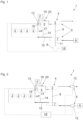
- FIG. 1 and Figure 2 show various embodiments of an internal combustion engine according to the invention in schematic representations.
- the basic functionality of the underlying internal combustion engine is the same. This basic functionality is briefly described below: Air A (usually ambient air) is sucked in and compressed in a compressor 7 of the turbocharger 4. The compressed masses reach the piston-cylinder units 2 via the supply line 15, whereby four piston-cylinder units 2 are shown here purely as an example.
- a fuel-air mixture (in addition to the fuel-air mixture that is fed through the catalyst when the internal combustion engine is switched off) must also be provided for combustion in the piston-cylinder units 2.
- This can be done either by a gas mixer (not shown) that is connected upstream of the compressor 7 (mixture-charged engine). Or the gas mixer can be arranged in the supply line 15 (air-charged engines).
- Controlled or regulated fuel injection devices can be used directly on the piston-cylinder units 2.
- the material content is removed from the piston-cylinder units 2 and fed to the catalyst 5 via a connecting line 16.
- the material flow After flowing through the catalyst 5, the material flow reaches the exhaust turbine 3 of the turbocharger 4 and finally exits as exhaust gas.
- the exhaust turbine 3 is connected to the compressor 7 of the turbocharger 4 via a common shaft 9, so that the exhaust turbine 3 drives the compressor 7 to generate the boost pressure.
- the two embodiments shown also have a mixing device 13. Via this mixing device 13, fuel F from a fuel reservoir (usually a tank) or from the fuel supply of the internal combustion engine (not shown) 1 is added to the air flow generated by the fluid conveying device 6 - the fuel-air mixture is created, which is conveyed through the catalyst 5.
- a mixing device 13 fuel F from a fuel reservoir (usually a tank) or from the fuel supply of the internal combustion engine (not shown) 1 is added to the air flow generated by the fluid conveying device 6 - the fuel-air mixture is created, which is conveyed through the catalyst 5.
- FIG. 1 Also common to both depictions is Figure 1 and Figure 2 the bypass line 14, which connects the supply line 15 with the connecting line 16.
- the mixing device 13 does not have to be arranged exclusively at the location shown. For example, it could also be arranged in the supply line 15, in the bypass line 14 or upstream of the compressor 7. Ultimately, it is also possible not to use a separate mixing device 13. A device can also be used which serves to produce the fuel-air mixture for combustion in the piston-cylinder units 2.
- a shut-off valve 17 can preferably be provided in the bypass line 14. This can be shut off during operation so that no direct material flow occurs between the supply line 15 and the connecting line 16.
- a catalyst bypass line 19 is also provided, in which a valve 20 is preferably also arranged.
- the temperature in the exhaust system after the catalyst 5 can also be regulated via the catalyst bypass line 19 around the catalyst 5 and the mixing device 13, which flows back in before the exhaust turbine 3 of the turbocharger 4, and the valve 20 (e.g. using a temperature sensor in/after the junction) in order to avoid temperature peaks for the turbocharger and downstream components of the exhaust system.
- This system can also prevent or at least reduce the cooling of any downstream SCR.
- SCR Selective Catalytic Reduction , is the term used to describe a catalyst in which certain catalytic reactions are carried out to selectively reduce certain emissions, usually nitrogen oxides, by previously adding a reducing agent, usually an aqueous urea solution, to the exhaust gas stream.
- the fluid conveying device 6 is formed by the compressor 7 in connection with the - in this case electrically designed - motor 8, whereby the output 11 of the motor 8 is connected to the common shaft 9 of the turbocharger 4. If the internal combustion engine 1 is switched off, the compressor 7 driven by the motor 8 can initially convey air through the bypass line 14 and the piston-cylinder units 2. As described a little further above, in the mixing device 13, by adding Fuel is the fuel-air mixture which is conveyed through the catalyst 5. The catalytic reaction in the catalyst 5 generates heat, which preheats the catalyst 5 before the start of the internal combustion engine 1. When the internal combustion engine is started, the full enthalpy of the material flow discharged from the piston-cylinder units 2 can then be used to improve the effect of the exhaust turbine 3.
- a control or regulating device 18 is provided, which is connected on the one hand to the motor 8 and on the other hand to the mixing device 13. This control or regulating device 18 takes over control of the heating process described. For the sake of clarity, the additional connection between the control or regulating unit 18 with the shut-off valve 17 and the valve 20 is not shown.
- the control or regulating unit 18 can open the shut-off valve 17 when the internal combustion engine 1 is switched off, whereby the bypass line 14 can serve the purpose described. During operation, the control or regulating device 18 can then close the shut-off valve 17.
- the previously described regulation or control of the valve 20 can also be carried out by the control device 18.
- Both the shut-off valve 17 and the valve 20 can be designed as a shut-off valve, which completely prevents the passage of a material flow, or as a volume flow control valve or the like.
- FIG 2 shows two alternatives for the arrangement of a fan 12, which is designed separately from the turbocharger 4.
- the fan 12 forms the fluid conveying device 6, which is why the fan is connected to the control or regulating device 18 for this purpose.
- blower 12 in the supply line 15 and/or the connecting line 16.
- a combination of the compressor 7 and a blower 12 or several blowers 12 can also be used as the fluid conveying device 6.
- a further advantage of a fluid conveying device according to the invention for conveying fuel-air mixture through the catalyst 5 is that when the internal combustion engine 1 is switched off, the exhaust tract can be pumped free of fuel-air mixture (so-called "purging"). This can take place after a normal operating stop of the internal combustion engine 1 or after a failed start attempt.
Landscapes
- Engineering & Computer Science (AREA)
- Chemical & Material Sciences (AREA)
- Combustion & Propulsion (AREA)
- Mechanical Engineering (AREA)
- General Engineering & Computer Science (AREA)
- Chemical Kinetics & Catalysis (AREA)
- Health & Medical Sciences (AREA)
- Toxicology (AREA)
- Exhaust Gas After Treatment (AREA)
- Supercharger (AREA)
Description
- Die vorliegende Erfindung betrifft Brennkraftmaschinen gemäß den Merkmalen des Oberbegriffs des Anspruchs 1 sowie ein Verfahren zum Vorbereiten eines Startvorgangs einer Brennkraftmaschine.
- Die
DE 10139526 A1 offenbart eine Brennkraftmaschine mit einem Turbolader, der mit einer elektrischen Maschine verbunden ist, und einem Porenbrenner. - Die
EP 2006178 A1 offenbart ein Hybridfahrzeug, wobei zum Warmhalten eines Katalysators die Kurbelwelle gedreht wird und dem Katalysator Treibstoff zugeführt wird. - Die
WO 2005/093235 A1 offenbart ein Fahrzeug, wobei mittels eines der Abgasturbine vorgeschalteten Katalysators und einer zusätzlichen Kraftstoffzufuhr ein Abgasmassenstrom durch die Abgasturbine erhöht wird. - Es ist demnach bekannt, zwischen den Kolben-Zylinder-Einheiten und der Abgasturbine eines Turboladers einen Katalysator anzuordnen. Insbesondere bei großvolumigen Gasmotoren hat dies den Vorteil, dass es möglich ist, die Wirkung des Turboladers zu verbessern. Denn durch die Freisetzung von chemischer Energie, welche sich nach der Verbrennung in den Kolben-Zylinder-Einheiten noch im abgeführten Stoffstrom gespeichert ist, führt zu einer höheren Temperatur des Stoffstroms und einer Expansion des Stoffstroms, welche sich in einem höheren Volumenstrom an der Abgasturbine des Turboladers niederschlägt. Der durch die Abgasturbine angetriebene Verdichter des Turboladers kann somit einen höheren Ladedruck verursachen, womit eine höhere Gesamtleistung der Brennkraftmaschine erreicht werden kann.
- Es ist zu bemerken, dass die im abgeführten Stoffstrom enthaltene Enthalpie gesteigert werden kann, indem Zündzeitpunkte der Kolben-Zylinder-Einheiten geeignet verschoben werden oder indem dem Stoffstrom Brennstoff zugeführt wird.
- Als Nachteil des Katalysators vor der Abgasturbine ist zu nennen, dass sich ein verschlechtertes Startverhalten ergibt. Denn die beim Start im Katalysator freigesetzte Energie wird zunächst zumindest teilweise in eine Erwärmung des Katalysators fließen, was die Zeitspanne bis zum Erreichen des Betriebspunkts der Brennkraftmaschine verlängern kann.
- Aufgabe der vorliegenden Erfindung ist es, eine Brennkraftmaschine sowie ein Verfahren anzugeben, durch welche ein verbessertes Startverhalten in der Brennkraftmaschine erzielt wird.
- Hinsichtlich der Brennkraftmaschine wird dies durch die Merkmale des Anspruchs 1 gelöst. Dies geschieht, indem eine Regeleinrichtung dazu ausgebildet ist, eine Fluidfördereinrichtung so zu regeln, dass die Fluidfördereinrichtung in einem Zustand der Brennkraftmaschine, in welchem keine Verbrennung und/oder Zündung in der wenigstens einen Kolben-Zylinder-Einheit stattfindet, Kraftstoff-Luft-Gemisch durch den Katalysator fördert.
- Hinsichtlich des Verfahrens wird die Aufgabe durch die Merkmale des Anspruchs 13 gelöst. Dabei wird ein Katalysator der Brennkraftmaschine in einem Zustand der Brennkraftmaschine, in welchem keine Verbrennung durchgeführt wird, vorgewärmt und/oder warm gehalten, indem ein Kraftstoff-Luft-Gemisch durch den Katalysator gefördert wird.
- Indem während Stillstandsphasen ein Kraftstoff-Luft-Gemisch durch den Katalysator gefördert wird, entsteht in demselben durch Freisetzung der Enthalpie des Kraftstoff-Luft-Gemisches Wärme, welche den Katalysator aufheizt. Wird dann die Brennkraftmaschine gestartet, liegt die positive Wirkung des Katalysators auf die Abgasturbine sofort vor, da weniger Energie für die Erwärmung der Umgebung (das heißt des Katalysators) verloren geht. Dadurch spricht der Turbolader schneller an, wodurch sich das Lastverhalten verbessert.
- Der Begriff Lastverhalten bezieht sich auf den Teil des Startvorgangs, in welchem die Leistung der Brennkraftmaschine erhöht wird (Lastrampe), nachdem eine erwünschte Solldrehzahl erreicht worden ist.
- Als rückgeführte Größen für die Regeleinrichtung werden erfindungsgemäß die Messwerte von Temperatursensoren verwendet, wobei die Temperatursensoren vor oder nach dem Katalysator oder im Katalysator angeordnet sein können. Zur weiteren Verbesserung des Regelverhaltens können motorspezifisch auch weitere Größen wie Druckverluste, Ventilöffnungen usw. im Regelmodell verarbeitet werden.
- Um den durch die Brennkraftmaschine verursachten Widerstand beim Fördern des Kraftstoff-Luft-Gemisches durch den Katalysator zu vermindern, ist erfindungsgemäß eine Umgehungsleitung zur Umgehung der zumindest einen Kolben-Zylinder-Einheit vorgesehen, welche strömungsmäßig mit einer Zufuhrleitung für Luft oder Kraftstoff-Luft-Gemisch zur zumindest einen Kolben-Zylinder-Einheit und einer Verbindungsleitung zwischen der zumindest einen Kolben-Zylinder-Einheit und dem Katalysator verbunden ist.
- Die Erfindung kann bevorzugt bei stationären Motoren und Marineanwendungen zum Einsatz kommen. Sie kann insbesondere bei Gasmotoren zum Einsatz kommen, welche vorzugsweise einen Generator zur Stromerzeugung antreiben (sogenannten Gensets). Die Erfindung kann bei Brennkraftmaschinen mit 8, 10, 12, 14, 16, 18, 20, 22, 24 oder mehr Zylindern zum Einsatz kommen.
- Vorteilhafte Ausführungsformen der Erfindung sind in den abhängigen Ansprüchen definiert.
- Die Fluidfördereinrichtung kann durch einen Verdichter des Turboladers selbst gebildet sein, in welchem Fall ein Motor zum Antrieb des Verdichters vorgesehen sein kann. Dies ist konstruktiv besonders einfach, da der Verdichter in vielen Fällen schon vorliegt und gegebenenfalls nur noch der Motor ergänzt werden muss.
- Weiterhin kann es eine besonders einfache Lösung darstellen, wenn ein Abtrieb des Motors mit einer gemeinsamen Welle der Abgasturbine und des Verdichters des Turboladers verbunden ist. Der Motor kann mittels einer Kupplung oder direkt mit der Welle verbunden sein. Der Motor kann elektrisch ausgeführt sein und vorzugsweise generatorisch betreibbar sein. Dies eröffnet mehrere Möglichkeiten. Zum einen kann während des Betriebs auch durch den Turbolader selbst Strom erzeugt werden (ähnlich zum Turbo-Charger-Compound). Anderseits kann der Elektromotor dazu verwendet werden, den Ladedruck zu erhöhen, falls dies notwendig ist.
- Die Fluidfördereinrichtung kann aber auch als zumindest ein Gebläse ausgebildet sein, welches vorzugsweise einem Verdichter des Turboladers vorgeschaltet und/oder der Abgasturbine nachgeschaltet ist. Damit müssen keine baulichen Veränderungen am Turbolader durchgeführt werden. Es ist zu bemerken, dass sowohl ein Gebläse, welches dem Verdichter des Turboladers vorgeschaltet ist, als auch ein Gebläse, welches der Abgasturbine nachgeschaltet ist, verwendet werden kann. Ein der Abgasturbine nachgeschaltetes Gebläse kann vorzugsweise korrosionsbeständig ausgeführt sein, da der Taupunkt des Motorabgases oft so liegt, dass Kondensationsfeuchte auftritt. Natürlich kann auch die Kombination zweier entsprechend angeordneter Gebläse vorgesehen sein.
- Das Kraftstoff-Luft-Gemisch kann bevorzugt in einer, vorzugsweise gesteuerten oder geregelten Mischeinrichtung erzeugt werden.
- Besonders bevorzugt kann die Mischeinrichtung strömungsmäßig zwischen der zumindest einen Kolben-Zylinder-Einheit und dem Katalysator angeordnet sein. Dadurch kann besonders einfach und gezielt die Enthalpie des durch den Katalysator geförderten Kraftstoff-Luft-Gemisches beeinflusst werden.
- Natürlich kann das Kraftstoff-Luft-Gemisch auch auf andere Art und Weise erzeugt werden. Hierzu kann zum einen die Mischeinrichtung einfach diejenige sein, welche das Gemisch für die Kolben-Zylinder-Einheiten erzeugt. Eine derartige Mischeinrichtung kann so ausgebildet und angeordnet sein, dass das Gemisch vor dem Eintritt in den Verdichter bereits vorliegt (gemischaufgeladene Motoren). Aber auch gesteuerte oder geregelte Ventile an den Kolben-Zylinder-Einheiten selbst oder in einer Zufuhrleitung zu denselben können zum Einsatz kommen (luftaufgeladene Motoren).
- Die Umgehungsleitung kann besonders bei Brennkraftmaschinen mit eher geringerer Anzahl von Kolben-Zylinder-Einheiten von Vorteil sein, da dann die Wahrscheinlichkeit geringer ist, dass Ein- und Auslassventile für eine Kolben-Zylinder-Einheit gleichzeitig offen sind und dadurch der Fall auftreten kann, dass durch die zumindest eine Kolben-Zylinder-Einheit kein Stoffstrom strömen kann.
- Um zu verhindern, dass ein Stoffstrom während des Verbrennungsbetriebs der Brennkraftmaschine durch die Umgehungsleitung fließt, kann in der Umgehungsleitung ein Absperrventil vorgesehen sein.
- In einer besonders bevorzugten Ausführungsform kann die Mischeinrichtung in der Verbindungsleitung angeordnet sein und die Verbindung der Umgehungsleitung mit der Verbindungsleitung kann strömungsmäßig vor der Mischeinrichtung angeordnet sein. Dabei kann der Beimischungsanteil an Kraftstoff zur Luft besonders gut gesteuert bzw. geregelt werden.
- Es kann vorgesehen sein, dass die Regeleinrichtung die Fluidfördereinrichtung vor einem Starten oder intermittierend während der Stillstandsphasen der Brennkraftmaschine aktiviert.
- Für eine besonders einfache Durchführung eines erfindungsgemäßen Verfahrens kann die steuerbare oder regelbare Mischeinrichtung mit der Regeleinrichtung verbunden sein und von dieser so gesteuert oder geregelt werden, dass die Mischeinrichtung das Kraftstoff-Luft-Gemisch herstellt, wenn die Fluidfördereinrichtung aktiviert ist.
- Auch das Absperrventil kann - vorzugsweise von der Regeleinrichtung - während des Verbrennungsbetriebs geschlossen und im abgeschalteten Zustand geöffnet werden.
- Der Katalysator kann über eine - vorzugsweise elektrische - Begleitheizung (auch Stillstandsheizung) verfügen. Dabei können zumindest eine Absperrklappe zum Einsatz kommen, um abkühlende Luftströmungen durch den Katalysator und den weiteren Abgastrakt zu verhindern.
- Es kann auch der Einsatz von elektrisch beheizbaren Katalysatorelementen vorgesehen sein, welche quasi eine Beheizung des Katalysators "von innen" erlauben. Insbesondere zusammen mit der erfindungsgemäßen Förderung von Kraftstoff-Luft-Gemisch durch den Katalysator können dadurch auch bei stärker ausgekühlten Systemen entsprechende Temperaturen im Katalysator erreicht werden, ohne den Katalysator gleichzeitig lokal zu überhitzen.
- Weitere Vorteile und Einzelheiten der Erfindung ergeben sich anhand der Figuren sowie der dazugehörigen Figurenbeschreibung. Dabei zeigen
- Fig. 1
- schematisch eine erfindungsgemäße Brennkraftmaschine mit einem Verdichter eines Turboladers als Fluidfördereinrichtung und
- Fig. 2
- schematisch eine erfindungsgemäße Brennkraftmaschine mit zwei Alternativen für die Anordnung eines Gebläses als Fluidfördereinrichtung.
-
Figur 1 und Figur 2 zeigen verschiedene Ausführungsformen einer erfindungsgemäßen Brennkraftmaschine in schematischen Darstellungen. Die grundsätzliche Funktionsweise der zugrundeliegenden Brennkraftmaschine ist die gleiche. Diese grundsätzliche Funktionsweise wird im Folgenden kurz beschrieben:
Luft A (meist Umgebungsluft) wird angesaugt und in einem Verdichter 7 des Turboladers 4 verdichtet. Über die Zufuhrleitung 15 gelangen die verdichteten Massen in die Kolben-Zylinder-Einheiten 2, wobei hier rein exemplarisch jeweils vier Kolben-Zylinder-Einheiten 2 dargestellt sind. Natürlich muss für die Verbrennung in den Kolben-Zylinder-Einheiten 2 ebenfalls ein Kraftstoff-Luft-Gemisch (neben dem Kraftstoff-Luft-Gemisch, welches in einem abgeschalteten Zustand der Brennkraftmaschine durch den Katalysator gefördert wird) bereitgestellt werden. Dies kann entweder durch einen Gasmischer (nicht dargestellt), welcher dem Verdichter 7 vorgeschaltet ist, geschehen (gemischaufgeladener Motor). Oder der Gasmischer kann in der Zufuhrleitung 15 angeordnet sein (luftaufgeladene Motoren). Alternativ oder zusätzlich können gesteuerte oder geregelte Kraftstoffeinbringungsvorrichtungen direkt an den Koben-Zylinder-Einheiten 2 eingesetzt werden. - Nach der Verbrennung in den Kolben-Zylinder-Einheiten 2 wird der Stoffinhalt aus den Kolben-Zylinder-Einheiten 2 abgeführt und über eine Verbindungsleitung 16 dem Katalysator 5 zugeführt. Nach dem Durchströmen des Katalysators 5 gelangt der Stoffstrom zur Abgasturbine 3 des Turboladers 4 und tritt schließlich als Abgas aus. Die Abgasturbine 3 ist über eine gemeinsame Welle 9 mit dem Verdichter 7 des Turboladers 4 verbunden, sodass die Abgasturbine 3 den Verdichter 7 zur Erzeugung des Ladedrucks antreibt.
- Die beiden dargestellten Ausführungsformen verfügen außerdem über eine Mischeinrichtung 13. Über diese Mischeinrichtung 13 wird dem durch die Fluidfördereinrichtung 6 erzeugten Luftstrom Kraftstoff F aus einem Kraftstoffreservoir (meist ein Tank) oder aus der Kraftstoffversorgung der Brennkraftmaschine (nicht dargestellt) 1 beigemengt - es entsteht das Kraftstoff-Luft-Gemisch, welches durch den Katalysator 5 gefördert wird.
- Ebenfalls gemein ist beiden Darstellungen aus
Figur 1 und Figur 2 die Umgehungsleitung 14, welche die Zufuhrleitung 15 mit der Verbindungsleitung 16 verbindet. - Es ist dabei auch zu bemerken, dass die Mischeinrichtung 13 nicht ausschließlich an der eingezeichneten Stelle angeordnet sein muss. Beispielsweise könnte sie auch in der Zufuhrleitung 15, in der Umgehungsleitung 14 oder dem Verdichter 7 vorgelagert angeordnet sein. Letztlich ist es auch möglich, keine separate Mischeinrichtung 13 zu verwenden. Denn es kann auch eine Vorrichtung zum Einsatz kommen, welche zur Herstellung des Brennstoff-Luft-Gemischs für die Verbrennung in den Kolben-Zylinder-Einheiten 2 dient.
- In der Umgehungsleitung 14 kann bevorzugt ein Absperrventil 17 vorgesehen sein. Dieses kann während des Betriebs abgesperrt werden, sodass kein direkter Stoffstrom zwischen der Zufuhrleitung 15 und der Verbindungsleitung 16 entsteht.
- In beiden Ausführungsbeispielen ist außerdem eine Katalysatorumgehungsleitung 19 vorgesehen, in welcher vorzugsweise ebenfalls ein Ventil 20 angeordnet ist.
- Über die Katalysatorumgehungsleitung 19 um den Katalysator 5 und die Mischeinrichtung 13, die vor der Abgasturbine 3 des Turboladers 4 wieder einmündet, und das Ventil 20 kann zusätzlich die Temperatur im Abgasstrang nach dem Katalysator 5 geregelt werden (z.B. mittels Temperaturfühler in / nach der Zusammenführung), um Temperaturspitzen für den Turbolader und nachgeschaltete Komponenten des Abgastrakts zu vermeiden. Mit diesem System kann außerdem das Abkühlen eines etwaigen nachgeschalteten SCR vermieden oder zumindest reduziert werden. (Mit SCR, Selective Catalytic Reduction, wird ein Katalysator bezeichnet, wobei durch vorherige Beimischung eines Reduktionsmittels, meist eine wässrige Harnstofflösung, zum Abgasstoffstrom bestimmte katalytische Reaktionen zur selektiven Reduktion von bestimmten Emissionen, meist Stickoxiden, durchgeführt wird.)
- In der konkreten Ausführung aus
Figur 1 ist die Fluidfördereinrichtung 6 durch den Verdichter 7 in Verbindung mit dem - in diesem Fall elektrisch ausgebildeten - Motor 8 gebildet, wobei der Abtrieb 11 des Motors 8 mit der gemeinsamen Welle 9 des Turboladers 4 verbunden ist. Ist die Brennkraftmaschine 1 abgeschaltet, kann durch den mittels des Motors 8 angetriebenen Verdichter 7 zunächst Luft durch die Umgehungsleitung 14 und die Kolben-Zylinder-Einheiten 2 gefördert werden. Wie etwas weiter oben beschrieben, entsteht dann in der Mischeinrichtung 13, durch die Zugabe von Kraftstoff das Kraftstoff-Luft-Gemisch, welches durch den Katalysator 5 gefördert wird. Durch die katalytische Reaktion im Katalysator 5 entsteht Wärme, wodurch der Katalysator 5 vor dem Start der Brennkraftmaschine 1 vorgeheizt wird. Beim Start der Brennkraftmaschine kann dann die volle Enthalpie des aus den Kolben-Zylinder-Einheiten 2 abgeführten Stoffstroms zur Verbesserung der Wirkung der Abgasturbine 3 dienen. - Es ist eine Steuer- oder Regeleinrichtung 18 vorgesehen, welche einerseits mit dem Motor 8 und andererseits mit der Mischeinrichtung 13 verbunden ist. Diese Steuer- oder Regeleinrichtung 18 übernimmt die Kontrolle über den beschriebenen Aufheizvorgang. Der Übersichtlichkeit halber ist die zusätzliche Verbindung zwischen der Steuer- oder Regeleinheit 18 mit dem Absperrventil 17 und dem Ventil 20 nicht dargestellt. Die Steuer- oder Regeleinheit 18 kann das Absperrventil 17 im abgeschalteten Zustand der Brennkraftmaschine 1 öffnen, wodurch die Umgehungsleitung 14 dem beschriebenen Zweck dienen kann. Während des Betriebs kann die Steuer- oder Regeleinrichtung 18 das Absperrventil 17 dann schließen.
- Die zuvor beschriebene Regelung oder Steuerung des Ventils 20 kann ebenfalls von der Regeleinrichtung 18 durchgeführt werden.
- Sowohl das Absperrventil 17 als auch das Ventil 20 kann jeweils als Sperrventil, welches das Passieren eines Stoffstromes vollständig verhindert, oder als Volumenstromregelventil oder dergleichen ausgeführt sein.
-
Figur 2 zeigt zwei Alternativen für die Anordnung eines Gebläses 12, welches vom Turbolader 4 separat ausgeführt ist. In diesem Fall bildet das Gebläse 12 die Fluidfördereinrichtung 6, weshalb das Gebläse hierfür mit der Steuer- oder Regeleinrichtung 18 verbunden ist. - Neben der Anordnung strömungsmäßig vor dem Verdichter 7 oder nach der Abgasturbine 3 kann natürlich auch eine Ausführungsform mit zwei Gebläsen 12 verwendet werden, welche, wie in
Figur 2 dargestellt, angeordnet sind. - Auch eine Anordnung eines Gebläses 12 in der Zufuhrleitung 15 und/oder der Verbindungsleitung 16 ist natürlich grundsätzlich möglich. Schließlich kann auch eine Kombination des Verdichters 7 und eines Gebläses 12 oder mehrerer Gebläse 12 als Fluidfördereinrichtung 6 verwendet werden.
- Ein weiterer Vorteil einer erfindungsgemäßen Fluidfördereinrichtung zur Förderung von Kraftstoff-Luft-Gemisch durch den Katalysator 5 besteht darin, dass im abgeschalteten Zustand der Brennkraftmaschine 1 der Abgastrakt von Kraftstoff-Luft-Gemisch freigepumpt werden kann (sogenanntes "purging"). Dies kann nach einem normalen Betriebsstopp der Brennkraftmaschine 1 oder nach einem fehlgeschlagenen Startversuch erfolgen.
Claims (15)
- Brennkraftmaschine mit- zumindest einer Kolben-Zylinder-Einheit (2),- einem eine Abgasturbine (3) aufweisenden Turbolader (4)- einem Katalysator (5), welcher zwischen die zumindest eine Kolben-Zylinder-Einheit (2) und die Abgasturbine (3) geschaltet ist, und- einer Regeleinrichtung (18),
wobei die Regeleinrichtung dazu ausgebildet ist, eine Fluidfördereinrichtung (6) so zu regeln, dass die Fluidfördereinrichtung in einem Zustand der Brennkraftmaschine (1), in welchem keine Verbrennung und/oder Zündung in der wenigstens einen Kolben-Zylinder-Einheit (2) stattfindet, Kraftstoff-Luft-Gemisch durch den Katalysator (5) fördert, dadurch gekennzeichnet, dass- ein Temperatursensor vor, nach oder im Katalysator (5) angeordnet ist, wobei die Regeleinrichtung (18) dazu ausgebildet ist, die Messwerte des Temperatursensors als rückgeführte Größen zu verwenden, und- eine Umgehungsleitung (14) zur Umgehung der zumindest einen Kolben-Zylinder-Einheit (2) vorgesehen ist, welche Umgehungsleitung (14) strömungsmäßig mit einer Zufuhrleitung (15) für Luft oder Kraftstoff-Luft-Gemisch zur zumindest einen Kolben-Zylinder-Einheit (2) und einer Verbindungsleitung (16) zwischen der zumindest einen Kolben-Zylinder-Einheit (2) und dem Katalysator (5) verbunden ist. - Brennkraftmaschine nach Anspruch 1, dadurch gekennzeichnet, dass die Fluidfördereinrichtung (6) als ein Verdichter (7) des Turboladers (4) ausgebildet ist, wobei ein Motor (8) zum Antrieb des Verdichters (7) vorgesehen ist.
- Brennkraftmaschine nach Anspruch 2, dadurch gekennzeichnet, dass ein Abtrieb (11) des Motors (8) mit einer gemeinsamen Welle (9) der Abgasturbine (3) und des Verdichters (7) des Turboladers (4) verbunden ist.
- Brennkraftmaschine nach Anspruch 2 oder 3, dadurch gekennzeichnet, dass der Motor (8) elektrisch ausgeführt ist und vorzugsweise generatorisch betreibbar ist.
- Brennkraftmaschine nach einem der Ansprüche 1 bis 4, dadurch gekennzeichnet, dass die Fluidfördereinrichtung (6) als zumindest ein Gebläse (12) ausgebildet ist, welches vorzugsweise einem Verdichter (7) des Turboladers (4) vorgeschaltet und/oder der Abgasturbine (3) nachgeschaltet ist.
- Brennkraftmaschine nach einem der Ansprüche 1 bis 5, dadurch gekennzeichnet, dass eine - vorzugsweise steuerbare oder regelbare - Mischeinrichtung (13) vorgesehen ist, mittels welcher das Kraftstoff-Luft-Gemisch herstellbar ist.
- Brennkraftmaschine nach Anspruch 6, dadurch gekennzeichnet, dass die Mischeinrichtung (13) strömungsmäßig zwischen der zumindest einen Kolben-Zylinder-Einheit (2) und dem Katalysator (5) angeordnet ist.
- Brennkraftmaschine nach Anspruch 6 oder 7, dadurch gekennzeichnet, dass die steuerbare oder regelbare Mischeinrichtung (13) mit der Regeleinrichtung (18) verbunden ist und von dieser so gesteuert oder geregelt wird, dass die Mischeinrichtung (13) das Kraftstoff-Luft-Gemisch herstellt, wenn die Fluidfördereinrichtung (6) aktiviert ist.
- Brennkraftmaschine nach einem der Ansprüche 6 bis 8, dadurch gekennzeichnet, dass die Mischeinrichtung (13) zur Versorgung mit Kraftstoff mit einem Kraftstoffreservoir und/oder einer Versorgungsleitung für die Brennkraftmaschine verbunden ist.
- Brennkraftmaschine nach einem der Ansprüche 6 bis 9, dadurch gekennzeichnet, dass die Mischeinrichtung (13) in der Verbindungsleitung (16) angeordnet ist und dass die Verbindung der Umgehungsleitung (14) mit der Verbindungsleitung (16) strömungsmäßig vor der Mischeinrichtung (13) angeordnet ist.
- Brennkraftmaschine nach einem der Ansprüche 1 bis 10, dadurch gekennzeichnet, dass in der Umgehungsleitung (14) ein Absperrventil (17) vorgesehen ist.
- Brennkraftmaschine nach einem der Ansprüche 1 bis 11, dadurch gekennzeichnet, dass der Katalysator (5) über eine - vorzugsweise elektrische - Begleitheizung verfügt.
- Verfahren zum Vorbereiten eines Startvorgangs einer Brennkraftmaschine (1) nach einem der Ansprüche 1 bis 12, wobei der Katalysator (5) der Brennkraftmaschine (1) in einem Zustand der Brennkraftmaschine (1), in welchem keine Verbrennung und/oder Zündung durchgeführt wird, vorgewärmt und/oder warm gehalten wird, indem ein Kraftstoff-Luft-Gemisch über die Umgehungsleitung (14) zur Umgehung der zumindest einen Kolben-Zylinder-Einheit (2) mittels der Regeleinrichtung (18) geregelt durch den Katalysator (5) gefördert wird, wobei die Umgehungsleitung (14) strömungsmäßig mit der Zufuhrleitung (15) für Kraftstoff-Luft-Gemisch zur zumindest einen Kolben-Zylinder-Einheit (2) und der Verbindungsleitung (16) zwischen der zumindest einen Kolben-Zylinder-Einheit (2) und dem Katalysator (5) verbunden ist und wobei Messwerte des vor dem, nach dem oder im Katalysator (5) angeordneten Temperatursensors als rückgeführte Größen für die Regeleinrichtung (18) verwendet werden.
- Verfahren nach Anspruch 13, dadurch gekennzeichnet, dass ein Motor (8) der einer Fluidfördereinrichtung (6) während eines Verbrennungsbetriebs der Brennkraftmaschine (1) generatorisch betrieben wird.
- Verfahren nach Anspruch 13 oder 14, dadurch gekennzeichnet, dass das Kraftstoff-Luft-Gemisch vor dem Start und/oder intermittierend während Stillstandszeiten der Brennkraftmaschine (1) durch den Katalysator (5) gefördert wird.
Applications Claiming Priority (2)
| Application Number | Priority Date | Filing Date | Title |
|---|---|---|---|
| ATA50756/2015A AT517669A1 (de) | 2015-09-04 | 2015-09-04 | Brennkraftmaschine |
| PCT/EP2016/070841 WO2017037286A1 (de) | 2015-09-04 | 2016-09-05 | Brennkraftmaschine |
Publications (3)
| Publication Number | Publication Date |
|---|---|
| EP3344864A1 EP3344864A1 (de) | 2018-07-11 |
| EP3344864C0 EP3344864C0 (de) | 2024-11-20 |
| EP3344864B1 true EP3344864B1 (de) | 2024-11-20 |
Family
ID=56936391
Family Applications (1)
| Application Number | Title | Priority Date | Filing Date |
|---|---|---|---|
| EP16766254.3A Active EP3344864B1 (de) | 2015-09-04 | 2016-09-05 | Brennkraftmaschine |
Country Status (5)
| Country | Link |
|---|---|
| US (1) | US10876482B2 (de) |
| EP (1) | EP3344864B1 (de) |
| CN (1) | CN107923330A (de) |
| AT (1) | AT517669A1 (de) |
| WO (1) | WO2017037286A1 (de) |
Families Citing this family (2)
| Publication number | Priority date | Publication date | Assignee | Title |
|---|---|---|---|---|
| DE102018201278A1 (de) * | 2018-01-29 | 2019-08-01 | Ford Global Technologies, Llc | Kraftfahrzeug mit Verbrennungsmotor und einer Elektromaschine zum Antreiben einer Turbine oder eines Verdichters sowie einer Heizung der Abgasnachbehandlungseinrichtung sowie ein Verfahren zum Betrieb dieses Kraftfahrzeugs |
| DE102019128334A1 (de) * | 2019-10-21 | 2021-04-22 | Volkswagen Aktiengesellschaft | Spülfluid-Versorgung einer aktiven Vorkammer eines aufgeladenen Ottomotors in Kombination mit einer Turbokühlung |
Citations (1)
| Publication number | Priority date | Publication date | Assignee | Title |
|---|---|---|---|---|
| US20120117962A1 (en) * | 2009-07-24 | 2012-05-17 | Vandyne Ed | Rich fuel mixture super-turbocharged engine system |
Family Cites Families (38)
| Publication number | Priority date | Publication date | Assignee | Title |
|---|---|---|---|---|
| FR2283314A1 (fr) * | 1974-08-01 | 1976-03-26 | France Etat | Perfectionnements apportes aux moteurs a combustion interne suralimentes, a allumage par compression |
| DE4139291B4 (de) * | 1991-11-29 | 2005-08-18 | Audi Ag | Vorrichtung zum Betreiben einer Brennkraftmaschine mit Abgasturboaufladung |
| US5410876A (en) * | 1993-09-17 | 1995-05-02 | Ford Motor Company | Catalytic converter assembly with bypass |
| BR9708311A (pt) * | 1996-03-05 | 1999-08-03 | Swissauto Eng Sa | Motor de ciclo otto com carregador por onda de pressão |
| EP0899436B1 (de) * | 1997-08-29 | 2003-01-29 | Swissauto Engineering S.A. | Verbrennungsmaschine mit Druckwellenmaschine |
| DE10139526A1 (de) * | 2001-08-10 | 2003-02-20 | Daimler Chrysler Ag | Kraftfahrzeug |
| US6923167B2 (en) * | 2003-05-30 | 2005-08-02 | The Regents Of The University Of California | Controlling and operating homogeneous charge compression ignition (HCCI) engines |
| DE10327686A1 (de) * | 2003-06-20 | 2005-01-05 | Robert Bosch Gmbh | Brennkraftmaschine |
| DE102004013232A1 (de) * | 2004-03-18 | 2005-10-20 | Daimler Chrysler Ag | Verfahren und Vorrichtung zum Betrieb einer Brennkraftmaschine mit Abgasturboaufladung |
| JP4681284B2 (ja) * | 2004-11-18 | 2011-05-11 | 日野自動車株式会社 | 排気浄化装置 |
| US7174714B2 (en) * | 2004-12-13 | 2007-02-13 | Caterpillar Inc | Electric turbocompound control system |
| JP4720667B2 (ja) * | 2006-08-04 | 2011-07-13 | トヨタ自動車株式会社 | 内燃機関の蒸発燃料処理装置 |
| DE102006037649A1 (de) * | 2006-08-10 | 2008-02-14 | Fev Motorentechnik Gmbh | Gasmotor mit verbessertem instationären Verhalten |
| US7849682B2 (en) * | 2006-08-31 | 2010-12-14 | Caterpillar Inc | Exhaust treatment device having a fuel powered burner |
| JP4265667B2 (ja) * | 2007-02-23 | 2009-05-20 | トヨタ自動車株式会社 | 内燃機関の排気システム |
| DE602007011241D1 (de) * | 2007-06-19 | 2011-01-27 | Ford Global Tech Llc | Hybridfahrzeug, Antriebssystem für ein Hybridfahrzeug und Verfahren für eine Abgasverarbeitungsvorrichtung in einem solchen System |
| JP5081635B2 (ja) * | 2008-01-08 | 2012-11-28 | 本田技研工業株式会社 | 内燃機関の排気浄化装置 |
| US9951673B2 (en) * | 2008-04-05 | 2018-04-24 | Baohua Qi | Engine aftertreatment system with exhaust lambda control |
| US9291079B2 (en) * | 2008-04-05 | 2016-03-22 | Mi Yan | Engine aftertreatment system with exhaust lambda control |
| US8297050B2 (en) * | 2008-07-11 | 2012-10-30 | GM Global Technology Operations LLC | Nozzle diffuser mixer |
| US8109081B2 (en) * | 2009-05-19 | 2012-02-07 | GM Global Technology Operations LLC | Hydrocarbon selective catalytic reduction for NOx control with gasoline-fueled spark ignition engines using engine-out hydrocarbons |
| JP5185910B2 (ja) * | 2009-10-16 | 2013-04-17 | 三菱重工業株式会社 | ミラーサイクルエンジン |
| JPWO2011101898A1 (ja) * | 2010-02-17 | 2013-06-17 | トヨタ自動車株式会社 | 内燃機関の排気浄化装置 |
| JP2011252466A (ja) * | 2010-06-04 | 2011-12-15 | Hitachi Automotive Systems Ltd | 内燃機関のアイドルストップ時のパージ装置 |
| WO2012081061A1 (ja) * | 2010-12-17 | 2012-06-21 | トヨタ自動車株式会社 | 内燃機関の排気加熱装置およびその制御方法 |
| WO2012104894A1 (ja) * | 2011-01-31 | 2012-08-09 | トヨタ自動車株式会社 | 排気ガス昇温用バーナー装置 |
| WO2012140702A1 (ja) * | 2011-04-15 | 2012-10-18 | トヨタ自動車株式会社 | 内燃機関の排気浄化システム |
| WO2013030887A1 (ja) * | 2011-08-30 | 2013-03-07 | トヨタ自動車株式会社 | 燃料添加方法 |
| JP5613842B2 (ja) * | 2011-09-14 | 2014-10-29 | 日野自動車株式会社 | 燃料改質器及びこれを用いた排ガス浄化装置 |
| WO2013042196A1 (ja) | 2011-09-20 | 2013-03-28 | 日立造船株式会社 | ターボチャージャー制御システム及び制御方法 |
| US8938954B2 (en) * | 2012-04-19 | 2015-01-27 | Donaldson Company, Inc. | Integrated exhaust treatment device having compact configuration |
| US20150108384A1 (en) * | 2012-04-26 | 2015-04-23 | International Engine Intellectual Property Company, Llc | Variable exhaust mixing device |
| US20140007562A1 (en) * | 2012-07-05 | 2014-01-09 | Julian JUSTIN | Exhaust system having an aftertreatment module |
| US20140318111A1 (en) * | 2013-04-26 | 2014-10-30 | Caterpillar Inc. | Decomposition tube for an engine |
| US9303581B2 (en) * | 2013-09-18 | 2016-04-05 | Ford Global Technologies, Llc | Systems and methods for injecting gaseous fuel during an exhaust stroke to reduce turbo lag |
| DK178105B1 (en) | 2013-10-31 | 2015-05-26 | Man Diesel & Turbo Deutschland | A combustion engine system |
| AT516110B1 (de) * | 2014-07-21 | 2016-08-15 | Ge Jenbacher Gmbh & Co Og | Abgasnachbehandlungseinrichtung |
| JP2016153630A (ja) * | 2015-02-20 | 2016-08-25 | いすゞ自動車株式会社 | 排気浄化システム |
-
2015
- 2015-09-04 AT ATA50756/2015A patent/AT517669A1/de not_active Application Discontinuation
-
2016
- 2016-09-05 US US15/750,424 patent/US10876482B2/en active Active
- 2016-09-05 WO PCT/EP2016/070841 patent/WO2017037286A1/de not_active Ceased
- 2016-09-05 CN CN201680051008.8A patent/CN107923330A/zh active Pending
- 2016-09-05 EP EP16766254.3A patent/EP3344864B1/de active Active
Patent Citations (1)
| Publication number | Priority date | Publication date | Assignee | Title |
|---|---|---|---|---|
| US20120117962A1 (en) * | 2009-07-24 | 2012-05-17 | Vandyne Ed | Rich fuel mixture super-turbocharged engine system |
Also Published As
| Publication number | Publication date |
|---|---|
| CN107923330A (zh) | 2018-04-17 |
| EP3344864A1 (de) | 2018-07-11 |
| WO2017037286A1 (de) | 2017-03-09 |
| EP3344864C0 (de) | 2024-11-20 |
| AT517669A1 (de) | 2017-03-15 |
| US10876482B2 (en) | 2020-12-29 |
| US20190040803A1 (en) | 2019-02-07 |
Similar Documents
| Publication | Publication Date | Title |
|---|---|---|
| EP3475543B1 (de) | Verfahren und vorrichtung zur abgasnachbehandlung eines verbrennungsmotors | |
| EP3660287B1 (de) | Abgasnachbehandlungssystem sowie verfahren zur abgasnachbehandlung eines verbrennungsmotors | |
| EP2948655B1 (de) | Verfahren zum betreiben einer antriebseinrichtung sowie entsprechende antriebseinrichtung | |
| DE102010001118B4 (de) | Verfahren zum Betreiben einer Brennkraftmaschine mit einer Dampfkraftanlage | |
| DE102013215525B4 (de) | Leitsystem zum Zuführen von Luft und Abgasen zu einer Brennkraftmaschine hin und zum Abführen der von der Brennkraftmaschine erzeugten Abgase von der Brennkraftmaschine weg sowie Verfahren zum Betreiben eines derartigen Leitsystems | |
| DE102004009791A1 (de) | Verfahren zur beschleunigten Erwärmung einer Reinigungseinrichtung im Abgasstrang einer Brennkraftmaschine und Brennkraftmaschine | |
| EP1688607A2 (de) | Abgasrückführungssystem für eine Brennkraftmaschine sowie Abgasrückführungssystem | |
| DE102015110569A1 (de) | Verfahren zum reduzieren der aufwärmzeit einer nachbehandlungsvorrichtung und ein fahrzeugsystem dafür | |
| DE102017108185A1 (de) | Steuerung des Motorabgasgegendrucks nach einem Motorkaltstart | |
| DE102019135831A1 (de) | Katalysatorvorwärmungssteuerungsvorrichtung und -verfahren | |
| DE202009005251U1 (de) | Abgasreinigungsanlage | |
| EP3344864B1 (de) | Brennkraftmaschine | |
| DE102007005246A1 (de) | Brennkraftmaschine | |
| EP2789818A1 (de) | Antriebssystem | |
| DE102019206085A1 (de) | Verfahren zum Betreiben eines Verbrennungsmotors, Verbrennungsmotor | |
| DE102019131829B3 (de) | Verfahren zur Abgasnachbehandlung eines Verbrennungsmotors | |
| DE102021205533A1 (de) | Verfahren und Vorrichtung zum elektrischen Beheizen eines Abgaskatalysators | |
| DE102018110424A1 (de) | Wärmeregelsystem für fahrzeuge mit einem aktiven abgasbehandlungsmanagement | |
| EP2339154A1 (de) | Verfahren zum Betrieb einer einen Abgasturbolader aufweisenden Brennkraftmaschine und eine Brennkraftmaschine zur Durchführung des Verfahrens | |
| EP3441587B1 (de) | Verfahren zum betreiben eines verbrennungsmotors | |
| WO2019238297A1 (de) | Verfahren und steuergerät zum betreiben einer antriebsvorrichtung, antriebsvorrichtung | |
| WO2016059034A1 (de) | Verfahren und vorrichtung zur einstellung eines ladedruckes in einer brennkraftmaschine mit einem druckwellenlader | |
| DE102015220876A1 (de) | Vorrichtung zur Steuerung eines Verbrennungsmotors | |
| DE102018124693A1 (de) | Verbrennungsmotor und Verfahren zum Betrieb eines Verbrennungsmotors | |
| AT517668A1 (de) | Brennkraftmaschine |
Legal Events
| Date | Code | Title | Description |
|---|---|---|---|
| STAA | Information on the status of an ep patent application or granted ep patent |
Free format text: STATUS: THE INTERNATIONAL PUBLICATION HAS BEEN MADE |
|
| PUAI | Public reference made under article 153(3) epc to a published international application that has entered the european phase |
Free format text: ORIGINAL CODE: 0009012 |
|
| STAA | Information on the status of an ep patent application or granted ep patent |
Free format text: STATUS: REQUEST FOR EXAMINATION WAS MADE |
|
| 17P | Request for examination filed |
Effective date: 20180404 |
|
| AK | Designated contracting states |
Kind code of ref document: A1 Designated state(s): AL AT BE BG CH CY CZ DE DK EE ES FI FR GB GR HR HU IE IS IT LI LT LU LV MC MK MT NL NO PL PT RO RS SE SI SK SM TR |
|
| AX | Request for extension of the european patent |
Extension state: BA ME |
|
| DAV | Request for validation of the european patent (deleted) | ||
| DAX | Request for extension of the european patent (deleted) | ||
| RAP1 | Party data changed (applicant data changed or rights of an application transferred) |
Owner name: INNIO JENBACHER GMBH & CO OG |
|
| STAA | Information on the status of an ep patent application or granted ep patent |
Free format text: STATUS: EXAMINATION IS IN PROGRESS |
|
| 17Q | First examination report despatched |
Effective date: 20191014 |
|
| P01 | Opt-out of the competence of the unified patent court (upc) registered |
Effective date: 20230614 |
|
| GRAP | Despatch of communication of intention to grant a patent |
Free format text: ORIGINAL CODE: EPIDOSNIGR1 |
|
| STAA | Information on the status of an ep patent application or granted ep patent |
Free format text: STATUS: GRANT OF PATENT IS INTENDED |
|
| INTG | Intention to grant announced |
Effective date: 20240620 |
|
| GRAS | Grant fee paid |
Free format text: ORIGINAL CODE: EPIDOSNIGR3 |
|
| GRAA | (expected) grant |
Free format text: ORIGINAL CODE: 0009210 |
|
| STAA | Information on the status of an ep patent application or granted ep patent |
Free format text: STATUS: THE PATENT HAS BEEN GRANTED |
|
| AK | Designated contracting states |
Kind code of ref document: B1 Designated state(s): AL AT BE BG CH CY CZ DE DK EE ES FI FR GB GR HR HU IE IS IT LI LT LU LV MC MK MT NL NO PL PT RO RS SE SI SK SM TR |
|
| REG | Reference to a national code |
Ref country code: GB Ref legal event code: FG4D Free format text: NOT ENGLISH |
|
| REG | Reference to a national code |
Ref country code: CH Ref legal event code: EP |
|
| REG | Reference to a national code |
Ref country code: DE Ref legal event code: R096 Ref document number: 502016016807 Country of ref document: DE |
|
| REG | Reference to a national code |
Ref country code: IE Ref legal event code: FG4D Free format text: LANGUAGE OF EP DOCUMENT: GERMAN |
|
| U01 | Request for unitary effect filed |
Effective date: 20241210 |
|
| P04 | Withdrawal of opt-out of the competence of the unified patent court (upc) registered |
Free format text: CASE NUMBER: APP_66591/2024 Effective date: 20241216 |
|
| U07 | Unitary effect registered |
Designated state(s): AT BE BG DE DK EE FI FR IT LT LU LV MT NL PT RO SE SI Effective date: 20241219 |
|
| PG25 | Lapsed in a contracting state [announced via postgrant information from national office to epo] |
Ref country code: IS Free format text: LAPSE BECAUSE OF FAILURE TO SUBMIT A TRANSLATION OF THE DESCRIPTION OR TO PAY THE FEE WITHIN THE PRESCRIBED TIME-LIMIT Effective date: 20250320 Ref country code: HR Free format text: LAPSE BECAUSE OF FAILURE TO SUBMIT A TRANSLATION OF THE DESCRIPTION OR TO PAY THE FEE WITHIN THE PRESCRIBED TIME-LIMIT Effective date: 20241120 |
|
| PG25 | Lapsed in a contracting state [announced via postgrant information from national office to epo] |
Ref country code: ES Free format text: LAPSE BECAUSE OF FAILURE TO SUBMIT A TRANSLATION OF THE DESCRIPTION OR TO PAY THE FEE WITHIN THE PRESCRIBED TIME-LIMIT Effective date: 20241120 |
|
| PG25 | Lapsed in a contracting state [announced via postgrant information from national office to epo] |
Ref country code: NO Free format text: LAPSE BECAUSE OF FAILURE TO SUBMIT A TRANSLATION OF THE DESCRIPTION OR TO PAY THE FEE WITHIN THE PRESCRIBED TIME-LIMIT Effective date: 20250220 |
|
| PG25 | Lapsed in a contracting state [announced via postgrant information from national office to epo] |
Ref country code: GR Free format text: LAPSE BECAUSE OF FAILURE TO SUBMIT A TRANSLATION OF THE DESCRIPTION OR TO PAY THE FEE WITHIN THE PRESCRIBED TIME-LIMIT Effective date: 20250221 |
|
| PG25 | Lapsed in a contracting state [announced via postgrant information from national office to epo] |
Ref country code: PL Free format text: LAPSE BECAUSE OF FAILURE TO SUBMIT A TRANSLATION OF THE DESCRIPTION OR TO PAY THE FEE WITHIN THE PRESCRIBED TIME-LIMIT Effective date: 20241120 |
|
| PG25 | Lapsed in a contracting state [announced via postgrant information from national office to epo] |
Ref country code: RS Free format text: LAPSE BECAUSE OF FAILURE TO SUBMIT A TRANSLATION OF THE DESCRIPTION OR TO PAY THE FEE WITHIN THE PRESCRIBED TIME-LIMIT Effective date: 20250220 |
|
| PG25 | Lapsed in a contracting state [announced via postgrant information from national office to epo] |
Ref country code: SM Free format text: LAPSE BECAUSE OF FAILURE TO SUBMIT A TRANSLATION OF THE DESCRIPTION OR TO PAY THE FEE WITHIN THE PRESCRIBED TIME-LIMIT Effective date: 20241120 |
|
| PG25 | Lapsed in a contracting state [announced via postgrant information from national office to epo] |
Ref country code: SK Free format text: LAPSE BECAUSE OF FAILURE TO SUBMIT A TRANSLATION OF THE DESCRIPTION OR TO PAY THE FEE WITHIN THE PRESCRIBED TIME-LIMIT Effective date: 20241120 |
|
| PG25 | Lapsed in a contracting state [announced via postgrant information from national office to epo] |
Ref country code: CZ Free format text: LAPSE BECAUSE OF FAILURE TO SUBMIT A TRANSLATION OF THE DESCRIPTION OR TO PAY THE FEE WITHIN THE PRESCRIBED TIME-LIMIT Effective date: 20241120 |
|
| PLBE | No opposition filed within time limit |
Free format text: ORIGINAL CODE: 0009261 |
|
| STAA | Information on the status of an ep patent application or granted ep patent |
Free format text: STATUS: NO OPPOSITION FILED WITHIN TIME LIMIT |
|
| U20 | Renewal fee for the european patent with unitary effect paid |
Year of fee payment: 10 Effective date: 20250820 |
|
| PGFP | Annual fee paid to national office [announced via postgrant information from national office to epo] |
Ref country code: GB Payment date: 20250822 Year of fee payment: 10 |
|
| 26N | No opposition filed |
Effective date: 20250821 |