EP3344493B1 - Schutzelement für einen fahrzeugsitz, fahrzeugsitz - Google Patents
Schutzelement für einen fahrzeugsitz, fahrzeugsitz Download PDFInfo
- Publication number
- EP3344493B1 EP3344493B1 EP16760693.8A EP16760693A EP3344493B1 EP 3344493 B1 EP3344493 B1 EP 3344493B1 EP 16760693 A EP16760693 A EP 16760693A EP 3344493 B1 EP3344493 B1 EP 3344493B1
- Authority
- EP
- European Patent Office
- Prior art keywords
- tab
- protection element
- protective element
- vehicle seat
- tabs
- Prior art date
- Legal status (The legal status is an assumption and is not a legal conclusion. Google has not performed a legal analysis and makes no representation as to the accuracy of the status listed.)
- Active
Links
Images
Classifications
-
- B—PERFORMING OPERATIONS; TRANSPORTING
- B60—VEHICLES IN GENERAL
- B60N—SEATS SPECIALLY ADAPTED FOR VEHICLES; VEHICLE PASSENGER ACCOMMODATION NOT OTHERWISE PROVIDED FOR
- B60N2/00—Seats specially adapted for vehicles; Arrangement or mounting of seats in vehicles
- B60N2/64—Back-rests or cushions
- B60N2/66—Lumbar supports
- B60N2/667—Lumbar supports having flexible support member bowed by applied forces
-
- B—PERFORMING OPERATIONS; TRANSPORTING
- B60—VEHICLES IN GENERAL
- B60N—SEATS SPECIALLY ADAPTED FOR VEHICLES; VEHICLE PASSENGER ACCOMMODATION NOT OTHERWISE PROVIDED FOR
- B60N2/00—Seats specially adapted for vehicles; Arrangement or mounting of seats in vehicles
- B60N2/68—Seat frames
-
- B—PERFORMING OPERATIONS; TRANSPORTING
- B60—VEHICLES IN GENERAL
- B60N—SEATS SPECIALLY ADAPTED FOR VEHICLES; VEHICLE PASSENGER ACCOMMODATION NOT OTHERWISE PROVIDED FOR
- B60N2/00—Seats specially adapted for vehicles; Arrangement or mounting of seats in vehicles
- B60N2/68—Seat frames
- B60N2/682—Joining means
-
- B—PERFORMING OPERATIONS; TRANSPORTING
- B60—VEHICLES IN GENERAL
- B60N—SEATS SPECIALLY ADAPTED FOR VEHICLES; VEHICLE PASSENGER ACCOMMODATION NOT OTHERWISE PROVIDED FOR
- B60N2/00—Seats specially adapted for vehicles; Arrangement or mounting of seats in vehicles
- B60N2/70—Upholstery springs ; Upholstery
- B60N2/7023—Coach-like constructions
- B60N2/7035—Cushions
- B60N2/7041—Fixation of covers and springs
-
- B—PERFORMING OPERATIONS; TRANSPORTING
- B60—VEHICLES IN GENERAL
- B60N—SEATS SPECIALLY ADAPTED FOR VEHICLES; VEHICLE PASSENGER ACCOMMODATION NOT OTHERWISE PROVIDED FOR
- B60N2/00—Seats specially adapted for vehicles; Arrangement or mounting of seats in vehicles
- B60N2/70—Upholstery springs ; Upholstery
- B60N2/7023—Coach-like constructions
- B60N2/7035—Cushions
- B60N2/7047—Springs
Definitions
- the invention relates to a planar-shaped protective element for a backrest of a vehicle seat, with at least one integrally formed with the protective element mounting hook for securing the protective element to a strut structure of the vehicle seat, wherein the fastening hook of the protective element by at least one free-cut and elastically bent out of a plane of the protective element tab of Protective element is formed.
- the invention relates to a vehicle seat for a motor vehicle with a backrest having such a protective element.
- Protective elements and vehicle seats of the type mentioned are known from the prior art. From the publication DE 10 2006 049 688 A1 already a protective element with the features of the preamble of claim 1 is known.
- the protective element has a centrally cut-out tab, which can be bent out of the plane of the protective element in order to be fastened to a seat structure of a backrest.
- a vehicle seat in the backrest of a plan-shaped protective element is arranged, which is formed as a woven spring structure and fixed by edge-side metal mounting bracket, which represent attachment hooks in this respect, to the vehicle seat.
- the protective element is insofar as a multi-part component, consisting of the fabric and the mounting brackets formed.
- the invention has for its object to provide an improved protective element, which provides a secure hold of the protective element on the strut structure of the vehicle seat.
- the protective element having the features of claim 1.
- This has the advantage that its use is particularly variable compared to previously known solutions, because fixed mounting hooks that do not tolerate any space or vehicle seat design, are avoided, while still ensuring that a secure attachment through the mounting hooks of the protection element a vehicle seat is guaranteed.
- the tab has an additional retaining portion for locking the tab on the strut structure.
- the invention thus provides that at least one tab is cut free in the protective element.
- the tab is in its initial state in the plane of the planar protective element, is therefore not from this or before. Due to the free-cutting, however, the tab can be bent out of the plane of the protective element or out of the protective element, thereby forming the fastening hook.
- the tab only needs to be bent out so far that a receiving space between the tab and the rest of the protective element is formed, in which the strut can be inserted.
- the tab protrudes from the protective element only when it is needed. Is at the point at which the tab is formed, no strut or no attachment of the protective element provided on the vehicle seat, the tab can remain in its initial position in the plane of the protective element and thus optimally fits into the existing space of the vehicle seat.
- the tab is also securely fastened to the strut structure such that accidental release of the protective element of the strut structure is reliably prevented.
- the additional retention portion is configured to engage behind the strut structure received between the tab and the protective member such that the strut structure on the tab is also retained between the tab and the retention portion.
- the tab is positively held on the strut structure such that it is displaceable only in the direction of the strut structure, but not transversely thereto.
- the protective element has a plurality of such tabs, which are bent depending on the vehicle seat on which the protective element is to be attached, bent or left in its initial position. This allows a high variety of uses of the protective element even with different vehicle seats and at the same time ensures a simple and secure installation of the protective element.
- the tab is formed at least partially elastically deformable. This results in the advantage that the tab can be easily bent out of its initial position or from its relaxed rest position in the protective element in the use position forming the fastening hooks. Due to the elasticity is further achieved that the mounting of the protective element on the vehicle seat can be done easily and without play.
- the protective element is designed to be elastically deformable as a whole, whereby the elastic deformability of the tab is advantageously ensured.
- the protective element is made of a puncture resistant material, in order to ensure a high level of security against puncturing of the vehicle seat, for example when used in a police car or taxi.
- the tab is cut free arc.
- corners or edges are avoided, which could result in an undesirable bending out of the tab during assembly.
- forces that occur during elastic deformation of the tab are advantageously absorbed by the protective element.
- a simple threading of a strut between the bent-out tab and the protective element is ensured by the arch shape.
- the tab is cut free at least substantially U-shaped. This results in particular the advantages already mentioned above.
- results from the U-shape of the advantage that the tab can be made relatively long even with a smaller radius of the arch shape, so that even with a narrow design of the tab, a strut between tab and protective element can be safely absorbed.
- the invention provides that the tab has at its free end a tab head, which is wider than the rest of the tab and forms the retaining portion.
- the tab head forms a portion which can engage behind the strut during assembly also, whereby the load capacity of the attachment by the of Tab formed fastening hook is further increased.
- the widespread tab head or the retention section forms a kind of barb, in particular allows, for example, to insert the tab in a corresponding counterpart and to lock there, such as in a slot-shaped opening in a housing part of the vehicle seat.
- the widened tab head thus provides the additional retention section of the tab in a simple manner.
- the protective element has at least one pair of two of the cut-free tabs, wherein the free ends of the oppositely arranged tabs have in the relaxed rest state of the tabs in the protective element in opposite directions.
- This design of the pair of tabs ensures that receiving pockets are formed, which are accessible from opposite directions, so that when both receiving pockets are used to receive a strut of the vehicle seat, a higher load capacity of the protective element is achieved by the improved attachment.
- the protective element is arranged fixed against displacement on the vehicle seat by the fastening hooks thus formed.
- the elastic deformability of the tabs still allows easy mounting of the protective element on the vehicle seat.
- the two tabs of the tab pair are spaced from each other.
- one tab is assigned to one side edge and the other tab is assigned to the opposite side edge of the protective element.
- the tabs of the tab pair may be arranged close to each other, for example, to grip two mutually parallel and closely spaced struts of the vehicle seat.
- a tab is preferably narrower than the other tab of the tab pair. Due to the different widths formed tabs, for example, the advantage is achieved that a curved strut, which is U-shaped, can be guided by both tabs of the tab pair and locks particularly stable the protective element on the strut.
- the one tab is formed by at least one pair of tabs in the other tab of the tab pair and forms the retaining portion.
- the one tab when the other tab is bent out of its rest position, already bent out of the plane of the protective element. If, subsequently, one tab is also bent out of its rest position, it can, for example, also lie parallel to the plane of the protective element.
- the protective element has at least two identical pairs of tabs, which are arranged parallel to one another at a height of the protective element.
- the tab pairs are adjacent to each other on a horizontal of the protective element or in the installed state of the vehicle seat. This ensures that the protective element does not tilt on the vehicle seat during operation.
- further tabs or pairs of tabs, as described above, are formed on / in the protective element.
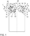
- FIG. 1 shows a simplified plan view of a protective element 1 for a vehicle seat of a motor vehicle.
- the protective element 1 is formed like a sheet and serves as a cover, in particular in a backrest of the vehicle seat.
- the protective element 1 is to beispielswese between a cushion or upholstery and a lumbar mechanism of the vehicle seat arranged to protect the upholstery or the upholstery and the user of the vehicle seat against hard components of the lumbar mechanism and especially against sharp edges of the lumbar mechanism and to dampen noise.
- the provision Plan-shaped protective elements as backrest cover or cover a lordosis mechanism is basically known.
- the present protective element 1 is made of an elastic material that can be adapted in particular to an adjustment of the lumbar mechanism and a user ensures the highest possible comfort on the vehicle seat.
- the protective element 1 is made of a puncture resistant (safety) material.
- the protective element 1 has in the plan view FIG. 1 a substantially rectangular contour, with two longitudinal sides and two shorter sides compared to shorter formed. On one of the broad sides, the protective element 1 on a mounting portion 2, which is used for fastening the protective element 1 to a vehicle seat, as for example in FIGS. 2 to 5 shown serves.
- the attachment portion 2 has a shape deviating from the rectangular shape of the protection member 1.
- the attachment portion 2 spaced from the edge of the broad side on two oppositely formed recesses 3, through which the protective element 1 is partially tapered in width.
- the attachment portion 2 is more flexible compared to the rest of the protective element 1.
- the attachment portion 2 at the edge of its broad side on a central and arcuate recess 4, which extends to the height of the recesses 3 in the protective element 1 into it. This results in the attachment portion 2, two fastening portions 5, which are formed tab-shaped.
- the attachment portion 2 further comprises four pairs 6, 7, 8 and 9 of tabs, which will be described in more detail below.
- the pair 6 has a first tab 10 and a second tab 11.
- the tabs 11 and 10 are formed in the protective element 1 by a respective free cut, so that they ultimately form cut-free tongues of the protective element 1.
- the respective free cut is arc-shaped, so that the tabs 10, 11 have a substantially arcuate contour, in particular a U-shaped contour.
- the free cuts have at their respective ends in each case a circular expansion opening 12, which ensures that when the respective tab 10, 11 is bent out of the plane of the protective element 1 elastically so that it protrudes from the rest of the protective element 1, which on the protective element acting forces in the region of the ends of the cutout do not lead to a tearing of the protective element 1.
- the tab 10 is formed wider than the tab 11, wherein the tab 11 lies completely in the tab 10 and forms an additional retaining portion 29.
- the tabs 10, 11 are formed such that the tabs 10,11, when they lie in their relaxed state of rest in the plane of the protective element 1 and in the protective element 1, with their freeERSfiegbaren from the protective element 1 ends 13 and 14 in opposite Directions.
- the tabs 10, 11 are further formed such that the tab 11 is formed centrally in the tab 10.
- the pair of tabs 6 and 9 is in such a way formed in the protective element 1 that it lies at the level of the recesses 3 in the protective element 1, wherein the flash openings 12 of the free cuts of the tabs 10 and 11 respectively at the same height of the protective element 1 and thus a horizontal line or on a line parallel to the broad side of the protective element 1 lie.
- the pair 9 is formed according to the pair 6, as already mentioned, so that the pair 9 also has tabs 10 and 11, which are formed and arranged as described above.
- the pair 9 is spaced apart from the pair 6 between the recesses 3 and is at the same height as the pair 6, so that the relaxation openings 12 of the free cuts and the expansion openings 12 of the parallel plates 10 and 11 are each at the same height or line.
- the pairs 7 and 8 also each have two tabs 15, 16.
- the pairs 7 and 8 are in each case formed in one of the fastening part sections 5.
- the tabs 15 and 16 are formed by a respective free cut in the protective element 1.
- the free cut of the tab 15 is arc-shaped, wherein the sheet has a substantially larger diameter in relation to the width of the free cut.
- the cutout of the tab 15 is in contrast to the cutouts of the tabs 16, 11 and 12 in the present case preferably designed as a slot, and alternatively the cutout of the tab 15 as the other free cuts could be formed with relaxation openings at the end.
- the tab 15 thus has a free end 17 which is less far out of the protective element 1 as compared to the tabs 11 and 10. Although the tab 15 is so far approximately as wide as the tab 10, but significantly shorter.
- the tab 16 also has a substantially U-shaped cutout, wherein the cutout at the free end 18 of the tab 16 has a broadening such that the tab 16 forms a widened tab head 19, which is thus formed wider compared to the rest of the tab 16 and thereby forms an additional retaining portion 30.
- the one tab 16 is not within the other tab 15, but rather the tab 16 is arranged at a distance from the tab 17.
- the free ends 18 and 17 are also oriented in the starting position or in the relaxed state of rest of the tabs 15, 16 pointing in opposite directions.
- the tab 16 is not centrally aligned with the tab 15, but slightly offset, so that the tab 16 and the center of the tab 16 is closer to the central longitudinal axis (dashed line) of the protective element 1, as the center of the tab 15.
- the pair 8 of tabs 15 and 16 of the pair 7 of the tabs 15 and 16 formed accordingly.
- the pairs of tabs 7 and 8 or 6 and 5 are reflected on the longitudinal central axis of the protective element 1.
- the protective element 1 Due to the advantageous embodiment of the protective element 1, this can be mounted on different vehicle seats in a simple manner without additional fastening means.
- the tabs are due to their free cutting in the protective element 1, so that their surfaces are flush with the surfaces of the protective element 1.
- several protective elements 1 can be easily stacked one above the other, in which they are placed on each other.
- this ensures an advantageous storage.
- the protective element 1 is particularly advantageous integrated into a vehicle seat, as will be shown in the following examples.
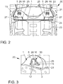
- FIG. 2 in this case shows a first embodiment of the mounted protective element 1.
- a section of a vehicle seat 20 in a plan view from the front, wherein of the vehicle seat 20 presently only a frame of a backrest 21 is shown.
- a strut structure 22 is arranged, which extends into an opening 23 formed by the frame.
- the strut structure 22 is formed elastically deformable at least in sections, and provides the remindlehen21 formed by the frame of the vehicle seat 20 has an advantageous elasticity for the user.
- the strut structure 22 thus ultimately provides a suspension for a pad of the vehicle seat 20.
- the strut structure 22 has in the present case a horizontally extending transverse strut 24, which extends so far horizontally on the frame over the opening 23 away.
- two vertical struts 25 are made firm, which run serpentine or meandering vertically upwards towards the upper end of the frame and are fastened there. Due to the serpentine shape, the vertical struts 25 receive an S-shaped profile in regions, each with an upwardly pointing rounded tip 26 and a downwardly pointing rounded tip 27.
- the protective element 1 is advantageously fastened to the strut structure 22.
- the protective element 1 is mounted such that the tip 26 is first pushed out under elastic bending out of the tab 15 under the fastening part section 5. In this case, the tip 26 is pushed over the discharge openings 12 of the cutout of the tab 16.
- the tab 16 is bent out to the back of the protective element 1, in such a way that it engages the vertical strut 25 at the top 26.
- the tab 15 is thus bent forward and the tab 16 to the rear out of the plane of the protective element 1 and from the plane of the paper.
- the retaining portion 30 or the widened tab head 19 hooks with the tip 26, so that the protective element 1 is securely held on the strut structure 22.
- the bent out tabs 15,16, in particular the narrower tabs 16 thus form attachment hooks for attachment of the protective element 1 to the vehicle seat 20 and / in the backrest 21st
- FIG. 3 shows an enlarged view of the mounting portions 5 in a view from behind.
- the lug 16 which has been bent out to the rear, and the lug 15, bent out towards the front, can be seen well.
- the widened tab head 19 ensures the secure hold of the tab 16 behind the vertical strut 25.
- the recesses 3 allow a total of increased flexibility of the fastener sections 5, so that they are securely adaptable to the shape of the strut structure 22.
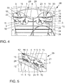
- FIG. 4 shows a further embodiment in which the protective element 1 is integrated into a backrest 21 of a vehicle seat 28, which differs from the backrest 21 of the vehicle seat 20.
- the protective element 1 is integrated into a backrest 21 of a vehicle seat 28, which differs from the backrest 21 of the vehicle seat 20.
- the pairs 6 and 9 are used in this case.
- the tabs 10 are bent out in the image plane to the front, and the tabs 11 to the rear.
- the tabs 10 are pushed over one of the transverse struts 24, so that the transverse strut 24 is located between the tab 10 and the protective element 1.
- the tabs 11 are bent so far back and guided under the strut 24 that they engage behind the same strut 24 as a retaining portion 29, which are covered by the tabs 10.
- the protective element 1 is positively locked securely on the strut structure 22 of the vehicle seat 28.
- FIG. 5 shows in an enlarged view a plan view of the back of the protective element 1 in the vehicle seat 28. It can be clearly seen that the strut 24 is held between the tab 11 and the tab 10 on the one hand and between the tab 10 and the protective element 1 on the other hand, so that the protective element 1 is limited in its freedom of movement both upwards and downwards, resulting in the secure attachment of the protective element 1 to the vehicle seat 28.
- the tabs 10, 11, 15 and 16 explained here can thus be used individually or not used depending on the application, that is, depending on the vehicle seat 20 or 28 to which the protective element 1 is to be attached.
- the tabs 10, 11, 15, 16 are bent out of the plane of the protective element 1, they each form their own attachment hook for locking the protective element 1 on the strut structure 22.
- the tabs that are not bent out of the plane of the protective element 1 and thus to Fixing the protective element 1 are not used, so remain in the plane of the protective element 1, so that the protective element 1 except for the sections in which the attachment is flat or flat remains and thus advantageous in the space of the respective vehicle seat 20, the 28th fits. In particular, a conflict with other elements in the installation space is avoided.
- the protective element 1 requires no further fastening elements and offers the advantage of lower storage costs, due to the variant reduction and the flat or planar structure in the raw state, lower logistics costs due to the variant reduction, improved utilization of tools during manufacture, a lower assembly time and reduced direct material costs.
- the protective element 1 is particularly advantageous when used as backrest or Lordosenabdecku ng.
Landscapes
- Engineering & Computer Science (AREA)
- Aviation & Aerospace Engineering (AREA)
- Transportation (AREA)
- Mechanical Engineering (AREA)
- Seats For Vehicles (AREA)
Description
- Die Erfindung betrifft ein planenförmiges Schutzelement für eine Rückenlehne eines Fahrzeugsitzes, mit wenigstens einem einstückig mit dem Schutzelement ausgebildeten Befestigungshaken zur Befestigung des Schutzelements an einer Strebenstruktur des Fahrzeugsitzes, wobei der Befestigungshaken des Schutzelements durch wenigstens eine freigeschnittene und elastisch aus einer Ebene des Schutzelements herausgebogene Lasche des Schutzelements gebildet ist.
- Ferner betrifft die Erfindung einen Fahrzeugsitz für ein Kraftfahrzeug mit einer Rückenlehne, die ein derartiges Schutzelement aufweist.
- Schutzelemente und Fahrzeugsitze der eingangs genannten Art sind aus dem Stand der Technik bekannt. Aus der Offenlegungsschrift
DE 10 2006 049 688 A1 ist bereits ein Schutzelement mit den Merkmalen des Oberbegriffs des Anspruchs 1 bekannt. Das Schutzelement weist eine mittig freigeschnittene Lasche auf, die aus der Ebene des Schutzelements herausbiegbar ist, um an einer Sitzstruktur einer Rückenlehne befestigt zu werden. - Weiterhin zeigt die Offenlegungsschrift
DE 42 24 063 A1 einen Fahrzeugsitz, in dessen Rückenlehne ein planenförmiges Schutzelement angeordnet ist, das als gewebte Federstruktur ausgebildet und durch randseitige Metall-Montagebügel, die insoweit Befestigungshaken darstellen, an dem Fahrzeugsitz befestigt ist. Das Schutzelement ist insofern als mehrteiliges Bauteil, bestehend aus dem Gewebe und den Montagebügeln, ausgebildet. - Aus der Offenlegungsschrift
US 2015/0032037 A1 ist ein weiteres Schutzelement bekannt, das ebenfalls planenförmig und elastisch verformbar ausgebildet ist, und durch Befestigungshaken an Streben des Fahrzeugsitzes befestigt ist. Die Befestigungshaken sind dabei einstückig mit dem Schutzelement ausgebildet und stehen von diesem rechtwinklig ab, sodass sie jeweils einen Abschnitt einer Strebe zur Befestigung aufnehmen können. In diesem Fall weist das Schutzelement somit eine dreidimensionale Grundstruktur mit einem planenförmigen Grundelement und davon abstehenden Befestigungshaken auf. Ein ähnliches Schutzelement ist auch bereits aus der OffenlegungsschriftUS 2013/0119724 A1 bekannt. - Aus der Offenlegungsschrift
US 2,096,822 A1 ist außerdem eine Polsterung mit einem Überzug bekannt, der an einem Gestell mithilfe mehrerer Klammern befestigt ist. - Der Erfindung liegt die Aufgabe zugrunde, ein verbessertes Schutzelement zu schaffen, das einen sichereren Halt des Schutzelements an der Strebenstruktur des Fahrzeugsitzes bietet.
- Die der Erfindung zugrundeliegende Aufgabe wird durch das Schutzelement mit den Merkmalen des Anspruchs 1 gelöst. Dieses hat den Vorteil, dass seine Verwendung im Vergleich zu bisher bekannten Lösungen besonders variabel ist, weil feststehende Befestigungshaken, die sich nicht mit jedem Bauraum beziehungsweise Fahrzeugsitzdesign vertragen, vermieden werden, wobei dennoch gewährleistet ist, dass eine sichere Befestigung durch die Befestigungshaken des Schutzelements an einem Fahrzeugsitz gewährleistet wird. Erfindungsgemäß ist hierzu vorgesehen, dass die Lasche einen zusätzlichen Rückhalteabschnitt zum Arretieren der Lasche an der Strebenstruktur aufweist. Die Erfindung sieht also vor, dass in dem Schutzelement wenigstens eine Lasche freigeschnitten ist. Damit liegt die Lasche in ihrem Ausgangszustand in der Ebene des planenförmigen Schutzelements, steht von diesem also nicht ab beziehungsweise vor. Aufgrund des Freischnitts, lässt sich die Lasche jedoch aus der Ebene des Schutzelements beziehungsweise aus dem Schutzelement herausbiegen, um dadurch den Befestigungshaken zu bilden. Hierzu muss die Lasche lediglich derart weit herausgebogen werden, dass ein Aufnahmeraum zwischen der Lasche und dem übrigen Schutzelement gebildet wird, in welchen die Strebe eingeführt werden kann. Durch die Erfindung wird erreicht, dass die Lasche nur dann von dem Schutzelement vorsteht, wenn sie benötigt wird. Ist an der Stelle, an welcher die Lasche ausgebildet ist, keine Strebe vorhanden oder keine Befestigung des Schutzelements an dem Fahrzeugsitz vorgesehen, kann die Lasche in ihrer Ausgangsstellung in der Ebene des Schutzelements verbleiben und passt sich somit optimal in den vorhandenen Bauraum des Fahrzeugsitzes ein. Durch den Rückhalteabschnitt ist die Lasche außerdem sicher an der Strebenstruktur derart befestigbar, dass ein versehentliches Lösen des Schutzelements von der Strebenstruktur sicher verhindert wird. Insbesondere ist der zusätzliche Rückhalteabschnitt so ausgebildet, dass er die Strebenstruktur, die zwischen Lasche und Schutzelement aufgenommen wird, hintergreift, sodass die Strebenstruktur an der Lasche außerdem zwischen der Lasche und dem Rückhalteabschnitt gehalten ist. Dadurch ist die Lasche formschlüssig an der Strebenstruktur derart gehalten, dass sie lediglich in Richtung der Strebenstruktur verschiebbar, jedoch nicht quer dazu verlagerbar ist. Zweckmäßigerweise weist das Schutzelement mehrere derartige Laschen auf, die in Abhängigkeit von dem Fahrzeugsitz, an welchem das Schutzelement befestigt werden soll, herausgebogen oder in ihrer Ausgangsstellung gelassen werden. Dadurch wird eine hohe Verwendungsvielfalt des Schutzelements auch bei unterschiedlichen Fahrzeugsitzen ermöglicht und gleichzeitig eine einfache und sichere Montage des Schutzelements gewährleistet. Darüber hinaus wird dadurch, dass die Laschen freigeschnitten werden, eine einfache Herstellung des Schutzelements geboten, die zeit- und kostengünstig durchführbar ist. Auch wird durch die erfindungsgemäße Ausbildung des Schutzelementes erreicht, dass mehrere Schutzelemente, deren Laschen sich in ihrer Ausgangsstellung befinden, einfach durch aufeinanderlegen gelagert und transportiert werden können, wodurch sich die Logistik mit den Schutzelementen vereinfacht.
- Gemäss einem Ausführungsbeispiel ist vorgesehen, dass die Lasche zumindest bereichsweise elastisch verformbar ausgebildet ist. Dadurch ergibt sich der Vorteil, dass die Lasche leicht aus ihrer Ausgangsstellung beziehungsweise aus ihrer entspannten Ruhestellung in dem Schutzelement in die den Befestigungshaken bildende Benutzungsstellung herausgebogen werden kann. Durch die Elastizität wird weiterhin erreicht, dass die Montage des Schutzelementes an dem Fahrzeugsitz einfach und spielfrei erfolgen kann.
- Erfindungsgemäß ist vorgesehen, dass das Schutzelement insgesamt elastisch verformbar ausgebildet ist, wodurch die elastische Verformbarkeit der Lasche vorteilhaft gewährleistet wird. Zusätzlich ist vorzugsweise vorgesehen, dass das Schutzelement aus einem stichfesten Material gefertigt ist, um eine hohe Sicherheit gegen ein Durchstechen des Fahrzeugsitzes, beispielsweise bei der Verwendung in einem Polizeiwagen oder Taxi, zu gewährleisten.
- Gemäß einer vorteilhaften Weiterbildung der Erfindung ist vorgesehen, dass die Lasche bogenförmig freigeschnitten ist. Dadurch werden Ecken oder Kanten vermieden, die ein unerwünschtes Herausbiegen der Lasche bei der Montage zur Folge haben könnten. Darüber hinaus werden Kräfte, die beim elastischen Verformen der Lasche auftreten, durch das Schutzelement vorteilhaft aufgenommen. Darüber hinaus ist durch die Bogenform ein einfaches Einfädeln einer Strebe zwischen die herausgebogene Lasche und das Schutzelement gewährleistet. Insbesondere ist vorgesehen, dass die Lasche zumindest im Wesentlichen U-förmig freigeschnitten ist. Es ergeben sich hierdurch insbesondere die zuvor bereits genannten Vorteile. Darüber hinaus ergibt sich durch die U-Form der Vorteil, dass die Lasche auch bei einem kleineren Radius der Bogenform verhältnismäßig lang ausgebildet sein kann, sodass auch bei einer schmalen Ausbildung der Lasche eine Strebe zwischen Lasche und Schutzelement sicher aufgenommen werden kann.
- Im Weiteren ist erfindungsgemäß vorgesehen, dass die Lasche an ihrem freien Ende einen Laschenkopf aufweist, der breiter ist als die übrige Lasche und den Rückhalteabschnitt bildet. Dadurch bildet der Laschenkopf einen Abschnitt, der die Strebe bei der Montage außerdem hintergreifen kann, wodurch die Belastbarkeit der Befestigung durch den von der Lasche gebildeten Befestigungshaken weiter erhöht wird. Der verbreitete Laschenkopf beziehungsweise den Rückhalteabschnitt bildet insbesondere eine Art Widerhaken, der es ermöglicht, die Lasche beispielsweise in ein entsprechendes Gegenstück einzustecken und dort zu verrasten, wie beispielsweise in eine schlitzförmige Öffnung in einem Gehäuseteil des Fahrzeugsitzes. Durch den verbreiterten Laschenkopf wird somit der zusätzliche Rückhalteabschnitt der Lasche auf einfache Art und Weise zur Verfügung gestellt.
- Gemäß einer bevorzugten Weiterbildung der Erfindung ist vorgesehen, dass das Schutzelement mindestens ein Paar von zwei der freigeschnittenen Laschen aufweist, wobei die freien Enden der einander gegenüberliegend angeordneten Laschen im entspannten Ruhezustand der Laschen in dem Schutzelement in entgegengesetzte Richtungen weisen. Durch diese Ausbildung des Laschenpaares wird erreicht, dass Aufnahmetaschen gebildet werden, die aus entgegengesetzten Richtungen zugängig sind, sodass, wenn beide Aufnahmetaschen zur Aufnahme einer Strebe des Fahrzeugsitzes verwendet werden, eine höhere Belastbarkeit des Schutzelements durch die verbesserte Befestigung erreicht wird. Insbesondere wird erreicht, dass das Schutzelement verschiebefest an dem Fahrzeugsitz durch die so gebildeten Befestigungshaken angeordnet ist. Insbesondere die elastische Verformbarkeit der Laschen erlaubt dabei dennoch eine einfache Montage des Schutzelements an dem Fahrzeugsitz.
- Gemäß einer Weiterbildung der Erfindung ist bevorzugt vorgesehen, dass die zwei Laschen des Laschenpaares beabstandet zueinander angeordnet sind. So kann beispielsweise vorgesehen sein, dass eine Lasche einem Seitenrand und die andere Lasche dem gegenüberliegenden Seitenrand des Schutzelements zugeordnet ist. Auch können die Laschen des Laschenpaares nah zueinander angeordnet sein, um beispielsweise zwei parallel zueinander verlaufende und nah beieinander angeordnete Streben des Fahrzeugsitzes zu greifen.
- Weiterhin ist bevorzugt vorgesehen, dass eine Lasche bevorzugt schmaler ausgebildet ist als die andere Lasche des Laschenpaares. Durch die unterschiedlich breit ausgebildeten Laschen wird beispielsweise der Vorteil erreicht, dass eine gebogene Strebe, die U-förmig verläuft, durch beide Laschen des Laschenpaares führbar ist und besonders stabil das Schutzelement an der Strebe arretiert.
- Gemäß einer bevorzugten Weiterbildung der Erfindung ist vorgesehen, dass die eine Lasche von zumindest einem Laschenpaar in der anderen Lasche des Laschenpaares ausgebildet ist und den Rückhalteabschnitt bildet. Damit wird die eine Lasche, wenn die andere Lasche aus ihrer Ruhestellung herausgebogen wird, bereits mit aus der Ebene des Schutzelements herausgebogen. Wird anschließend auch die eine Lasche aus ihrer Ruhestellung herausgebogen, kann sie beispielsweise auch parallel zu der Ebene des Schutzelements liegen. Hierdurch ergeben sich weitere Gestaltungsmöglichkeiten für den Befestigungshaken zur Befestigung an dem Fahrzeugsitz, insbesondere an einer Strebe des Fahrzeugsitzes. Insbesondere kann hierdurch ein Hintergreifen der Strebe durch den Rückhalteabschnitt erreicht werden, durch welches ein ungewolltes Lösen des Schutzelements von dem Fahrzeugsitz sicher verhindert wird.
- Weiterhin ist bevorzugt vorgesehen, dass das Schutzelement wenigstens zwei gleiche Laschenpaare aufweist, die auf einer Höhe des Schutzelements parallel zueinander angeordnet sind. Damit liegen die Laschenpaare nebeneinander auf einer Horizontalen des Schutzelements beziehungsweise im verbautem Zustand des Fahrzeugsitzes. Hierdurch wird gewährleistet, dass das Schutzelement an dem Fahrzeugsitz im Betrieb nicht verkippt. Gemäß einer bevorzugten Weiterbildung sind noch weitere Laschen oder Laschenpaare, wie sie obenstehend beschrieben wurden, an/in dem Schutzelement ausgebildet.
- Der erfindungsgemäße Fahrzeugsitz mit den Merkmalen des Anspruchs 10 zeichnet sich durch das erfindungsgemäße Schutzelement aus. Es ergeben sich hierdurch die bereits genannten Vorteile. Weitere Vorteile und bevorzugte Merkmale ergeben sich aus dem zuvor Beschriebenen sowie aus den Ansprüchen.
- Im Folgenden soll die Erfindung anhand von Ausführungsbeispielen näher erläutert werden. Dazu zeigen:
- Figur 1
- ein Schutzelement für einen Fahrzeugsitz in einer Draufsicht,
- Figur 2
- einen Fahrzeugsitz mit dem darin montierten Schutzelement,
- Figur 3
- eine weitere Darstellung des Fahrzeugsitzes,
- Figur 4
- einen weiteren Fahrzeugsitz mit dem daran montiertem Schutzelement, und
- Figur 5
- den weiteren Fahrzeugsitz in einer weiteren Darstellung.
-
Figur 1 zeigt in einer vereinfachten Draufsicht ein Schutzelement 1 für einen Fahrzeugsitz eines Kraftfahrzeugs. Das Schutzelement 1 ist planenförmig ausgebildet und dient als Abdeckung insbesondere in einer Rücklehne des Fahrzeugsitzes. Das Schutzelement 1 ist dazu beispielswese zwischen einem Polster oder Polsterbezug und einer Lordosenmechanik des Fahrzeugsitzes angeordnet, um das Polster oder den Polsterbezug und auch den Benutzer des Fahrzeugsitzes vor harten Bestandteilen der Lordosenmechanik und insbesondere vor scharfen Kanten der Lordosenmechanik zu schützen und Geräusche zu dämmen. Das Vorsehen planenförmiger Schutzelemente als Lehnenabdeckung beziehungsweise Abdeckung einer Lordosenmechanik ist grundsätzlich bekannt. - Das vorliegende Schutzelement 1 ist aus einem elastischen Material gefertigt, das sich insbesondere an eine Verstellung der Lordosenmechanik anpassen kann und einem Benutzer den höchstmöglichen Komfort auf dem Fahrzeugsitz gewährleistet. Bevorzugt ist das Schutzelement 1 aus einem stichfesten (Sicherheits-)Material gefertigt.
- Das Schutzelement 1 weist dabei in der Draufsicht aus
Figur 1 eine im Wesentlichen rechteckförmige Kontur auf, mit zwei Längsseiten und zwei im Vergleich dazu kürzer ausgebildeten Breitseiten. An einer der Breitseiten weist das Schutzelement 1 einen Befestigungsabschnitt 2 auf, der zur Befestigung des Schutzelements 1 an einem Fahrzeugsitz, wie er beispielsweise inFiguren 2 bis 5 gezeigt ist, dient. - Der Befestigungsabschnitt 2 weist eine von der Rechteckform des Schutzelements 1 abweichende Form auf. Dazu weist der Befestigungsabschnitt 2 beabstandet zum Rand der Breitseite zwei einander gegenüberliegend ausgebildete Aussparungen 3 auf, durch welche das Schutzelement 1 in seiner Breite bereichsweise verjüngt ist. Damit ist der Befestigungsabschnitt 2 im Vergleich zum übrigen Schutzelement 1 flexibler. Weiterhin weist der Befestigungsabschnitt 2 am Rand seiner Breitseite eine mittige und bogenförmige Vertiefung 4 auf, die sich bis auf die Höhe der Aussparungen 3 in das Schutzelement 1 hinein erstreckt. Dadurch ergeben sich in dem Befestigungsabschnitt 2 zwei Befestigungsteilabschnitte 5, die laschenförmig ausgebildet sind.
- Der Befestigungsabschnitt 2 weist weiterhin vier Paare 6, 7, 8 und 9 von Laschen auf, die im Folgenden näher beschrieben werden sollen.
- Zunächst soll anhand des Paares 6 die Ausführung der Paare 6 und 7 erläutert werden, die gleich gestaltet sind. Das Paar 6 weist eine erste Lasche 10 und eine zweite Lasche 11 auf. Die Laschen 11 und 10 sind in dem Schutzelement 1 durch jeweils einen Freischnitt ausgebildet, sodass sie letztendlich freigeschnittene Zungen des Schutzelements 1 bilden. Der jeweilige Freischnitt ist dabei bogenförmig ausgebildet, sodass die Laschen 10, 11 eine im Wesentlichen bogenförmige Kontur, insbesondere eine U-förmige Kontur aufweisen. Die Freischnitte weisen an ihren jeweiligen Enden jeweils eine kreisförmige Entspannungsöffnung 12 auf, die gewährleistet, dass dann, wenn die jeweilige Lasche 10, 11 aus der Ebene des Schutzelements 1 elastisch herausgebogen wird, sodass sie vom übrigen Schutzelement 1 vorsteht, die auf das Schutzelement 1 wirkenden Kräfte im Bereich der Enden der Freischnitt nicht zu einem Einreißen des Schutzelements 1 führen.
- Gemäß dem vorliegenden Ausführungsbeispiel ist die Lasche 10 breiter ausgebildet als die Lasche 11, wobei die Lasche 11 vollständig in der Lasche 10 liegt und einen zusätzlichen Rückhalteabschnitt 29 bildet. Dabei sind die Laschen 10, 11 derart ausgebildet, dass die Laschen 10,11, wenn sie in ihrem entspannten Ruhezustand in der Ebene des Schutzelements 1 beziehungsweise in dem Schutzelement 1 liegen, mit ihren freien aus dem Schutzelement 1 herausbiegbaren Enden 13 beziehungsweise 14 in entgegengesetzte Richtungen weisen. Die Laschen 10, 11 sind weiterhin derart ausgebildet, dass die Lasche 11 mittig in der Lasche 10 ausgebildet ist. Das Paar der Laschen 6 beziehungsweise 9 ist dabei derart in dem Schutzelement 1 ausgebildet, dass es auf Höhe der Aussparungen 3 in dem Schutzelement 1 liegt, wobei die Entspannungsöffnungen 12 der Freischnitte der Laschen 10 und 11 jeweils auf derselben Höhe des Schutzelements 1 und somit auf einer horizontalen Linie beziehungsweise auf einer Linie parallel zur Breitseite des Schutzelementes 1 liegen.
- Das Paar 9 ist dem Paar 6 entsprechend ausgebildet ist, wie bereits erwähnt, sodass das Paar 9 ebenfalls Laschen 10 und 11 aufweist, die wie zuvor beschrieben ausgebildet und angeordnet sind. Das Paar 9 ist beabstandet zu dem Paar 6 zwischen den Aussparungen 3 angeordnet und liegt auf derselben Höhe wie das Paar 6, sodass die Entspannungsöffnungen 12 der Freischnitte beziehungsweise die Entspannungsöffnungen 12 der parallel angeordneten Laschen 10 und 11 jeweils auf der gleichen Höhe beziehungsweise Linie liegen.
- Die Paare 7 und 8 weisen ebenfalls jeweils zwei Laschen 15, 16 auf. Die Paare 7 und 8 sind dabei in jeweils einem der Befestigungsteilabschnitte 5 ausgebildet. Auch die Laschen 15 und 16 sind durch jeweils einen Freischnitt in dem Schutzelement 1 ausgebildet.
- Der Freischnitt der Lasche 15 ist dabei bogenförmig ausgebildet, wobei der Bogen einen im Verhältnis zur Breite des Freischnitts wesentlich größeren Durchmesser aufweist. Der Freischnitt der Lasche 15 ist dabei im Unterschied zu den Freischnitten der Laschen 16, 11 und 12 vorliegend bevorzugt als Langloch ausgeführt, wobei alternativ auch der Freischnitt der Lasche 15 wie die übrigen Freischnitte mit Entspannungsöffnungen am Ende ausgebildet sein könnte. Die Lasche 15 weist somit ein freies Ende 17 auf, das sich im Vergleich zu den Laschen 11 und 10 weniger weit aus dem Schutzelement 1 herausbiegen lässt. Die Lasche 15 ist insofern zwar ungefähr so breit wie die Lasche 10, jedoch deutlich kürzer ausgebildet.
- Die Lasche 16 weist ebenfalls einen im Wesentlichen U-förmigen Freischnitt auf, wobei der Freischnitt am freien Ende 18 der Lasche 16 eine Verbreiterung derart aufweist, dass die Lasche 16 einen verbreiterten Laschenkopf 19 bildet, der also im Vergleich zur übrigen Lasche 16 breiter ausgebildet ist und dadurch einen zusätzlichen Rückhalteabschnitt 30 bildet. Im Unterschied zu den Paaren 6 und 9 liegt die eine Lasche 16 nicht innerhalb der anderen Lasche 15, vielmehr ist die Lasche 16 beabstandet zu der Lasche 17 angeordnet. Die freien Enden 18 und 17 sind dabei jedoch in der Ausgangsstellung beziehungsweise im Entspannten Ruhezustand der Laschen 15, 16 ebenfalls in entgegengesetzte Richtungen weisend ausgerichtet. Dabei ist die Lasche 16 nicht mittig zur Lasche 15 ausgerichtet, sondern leicht versetzt dazu, sodass die Lasche 16 beziehungsweise das Zentrum der Lasche 16 näher zur Mittellängsachse (gestrichelte Linie) des Schutzelements 1 angeordnet ist, als das Zentrum der Lasche 15. Wie bereits erwähnt ist das Paar 8 von Laschen 15 und 16 dem Paar 7 der Laschen 15 und 16 entsprechend ausgebildet. Letztendlich spiegeln sich die Paare der Laschen 7 und 8 beziehungsweise 6 und 5 an der Längsmittelachse des Schutzelements 1.
- Durch die vorteilhafte Ausbildung des Schutzelements 1 kann dieses an unterschiedlichen Fahrzeugsitzen auf einfache Weise ohne zusätzliche Befestigungsmittel montiert werden. Im Ruhezustand beziehungsweise im Ausgangszustand des Schutzelements 1 liegen die Laschen aufgrund ihres Freischnitts in dem Schutzelement 1, sodass ihre Oberflächen bündig mit den Oberflächen des Schutzelements 1 abschließen. Dadurch können beispielsweise mehrere Schutzelemente 1 problemlos übereinander gestapelt werden, in dem sie aufeinander gelegt werden. Insbesondere im Vergleich zu Lösungen, bei welchen bekannte Schutzelemente einen dauerhaft vorstehenden Befestigungshaken aufweisen, ist hierdurch eine vorteilhafte Lagerung gewährleistet. Darüber hinaus ist das Schutzelement 1 besonders vorteilhaft in einen Fahrzeugsitz integrierbar, wie an den folgenden Beispielen gezeigt werden soll.
-
Figur 2 zeigt hierbei ein erstes Ausführungsbeispiel des montierten Schutzelements 1. Dazu zeigtFigur 2 einen Abschnitt eines Fahrzeugsitzes 20 in einer Draufsicht von vorne, wobei von dem Fahrzeugsitz 20 vorliegend nur ein Rahmengestell einer Rückenlehne 21 gezeigt ist. An dem Rahmengstell ist eine Strebenstruktur 22 angeordnet, die sich in eine von dem Rahmengestell gebildete Öffnung 23 hinein erstreckt. Die Strebenstruktur 22 ist zumindest Abschnittweise elastisch verformbar ausgebildet und bietet der von dem Rahmengestell gebildeten Rücklehen21 des Fahrzeugsitzes 20 eine vorteilhafte Elastizität für den Benutzer. Die Strebenstruktur 22 stellt somit letztendlich eine Federung für ein Polster des Fahrzeugsitzes 20 dar. Die Strebenstruktur 22 weist vorliegend eine horizontal verlaufende Querstrebe 24 auf, die sich insofern horizontal an dem Rahmengestells über die Öffnung 23 hinweg erstreckt. An der Quersterbe 24 sind zwei Vertikalstreben 25 fest gemacht, die serpentinen- oder mäanderförmig vertikal nach oben in Richtung des oberen Ende des Rahmengestells verlaufen und dort festgemacht sind. Durch die Serpentinenform erhalten die Vertikalstreben 25 bereichsweise einen S-förmigen Verlauf mit jeweils einer nach oben weisenden gerundeten Spitze 26 und einer nach unten weisenden gerundeten Spitze 27. - Durch Nutzung der Paare 7 und 8 von Laschen 15 und 16 ist das Schutzelement 1 vorteilhaft an der Strebenstruktur 22 festgemacht. Dazu ist das Schutzelement 1 derart montiert, dass die Spitze 26 zunächst unter elastischem herausbiegen der Lasche 15 unter dem Befestigungsteilabschnitt 5 geschoben ist. Dabei ist die Spitze 26 über die Entlastungsöffnungen 12 des Freischnitts der Lasche 16 hinausgeschoben. Die Lasche 16 ist zur Rückseite des Schutzelements 1 herausgebogen, und zwar derart, dass sie die Vertikalstrebe 25 an der Spitze 26 greift. Die Lasche 15 ist somit nach vorne und die Lasche 16 nach hinten aus der Ebene des Schutzelements 1 beziehungsweise aus der Papierebene herausgebogen. Der Rückhalteabschnitt 30 beziehungsweise der verbreiterte Laschenkopf 19 verhakt dabei mit der Spitze 26, sodass das Schutzelement 1 sicher an der Strebenstruktur 22 gehalten ist. Die herausgebogenen Laschen 15,16, insbesondere die schmalere Laschen 16 bilden somit Befestigungshaken zur Befestigung des Schutzelements 1 an dem Fahrzeugsitz 20 beziehungsweise in/an dessen Rückenlehne 21.
-
Figur 3 zeigt eine vergrößerte Darstellung der Befestigungsteilabschnitte 5 in einer Ansicht von hinten. Hierbei ist gut die nach hinten herausgebogene Lasche 16 und die nach vorne herausgebogene 15 zu erkennen. Der verbreiterte Laschenkopf 19 gewährleistet den sicheren Halt der Lasche 16 hinter der Vertikalstrebe 25. Die Aussparungen 3 erlauben insgesamt eine erhöhte Flexibilität der Befestigungsteilabschnitte 5, sodass diese sicher an die Form der Strebenstruktur 22 anpassbar sind. -
Figur 4 zeigt ein weiteres Ausführungsbeispiel, bei welchem das Schutzelement 1 in eine Rückenlehne 21 eines Fahrzeugsitzes 28, die sich von der Rückenlehne 21 des Fahrzeugsitzes 20 unterscheidet, integriert ist. Aus dem vorhergehenden Ausführungsbeispiel bekannte Elemente sind mit den gleichen Bezugszeichen versehen, sodass insofern auf die oben stehende Beschreibung verwiesen wird. Im Folgenden soll im Wesentlichen nur auf die Unterschiede eingegangen werde. - Im Unterschied zu dem vorhergehenden Ausführungsbeispiel weist die Strebenstruktur 22 eine Vielzahl von Querstreben 24 auf, die sich horizontal über die Öffnung 23 des Rahmens 21 beabstandet zueinander erstrecken. Zur Befestigung des Schutzelements 1 an der Strebenstruktur 22 sind in diesem Fall die Paare 6 und 9 verwendet. Dazu sind die Laschen 10 in der Bildebene nach vorne herausgebogen, und die Laschen 11 nach hinten. Die Laschen 10 sind über eine der Querstreben 24 geschoben, sodass die Querstrebe 24 zwischen der Lasche 10 und dem Schutzelement 1 liegt. Die Laschen 11 sind derart weit nach hinten gebogen und unter die Strebe 24 geführt, dass sie dieselbe Strebe 24 als Rückhalteabschnitt 29 hintergreifen, die von den Laschen 10 überdeckt werden. Dadurch ist das Schutzelement 1 formschlüssig sicher an der Strebenstruktur 22 des Fahrzeugsitzes 28 arretiert.
-
Figur 5 zeigt in einer vergrößerten Darstellung eine Draufsicht auf die Rückseite des Schutzelements 1 in dem Fahrzeugsitz 28. Dabei ist gut zu erkennen, dass die Strebe 24 zwischen der Lasche 11 und der Lasche 10 einerseits und zwischen der Lasche 10 und dem Schutzelement 1 andererseits gehalten ist, sodass das Schutzelement 1 in seiner Bewegungsfreiheit sowohl nach oben als auch nach unten beschränkt ist, wodurch sich die sichere Befestigung des Schutzelements 1 an dem Fahrzeugsitz 28 ergibt. - Die hier erläuterten Laschen 10, 11, 15 und 16 können somit je nach Anwendungsfall, also je nach Fahrzeugsitz 20 oder 28, an welchem das Schutzelement 1 befestigt werden soll, individuell verwendet oder nicht verwendet werden. Sobald die Laschen 10, 11, 15, 16 aus der Ebene des Schutzelements 1 herausgebogen werden, bilden sie jeweils einen eigenen Befestigungshaken zur Arretierung des Schutzelements 1 an der Strebenstruktur 22. Die Laschen, die nicht aus der Ebene des Schutzelements 1 herausgebogen und insofern zur Befestigung des Schutzelements 1 auch nicht genutzt werden, verbleiben damit in der Ebene des Schutzelements 1, sodass das Schutzelement 1 bis auf die Abschnitte, in welchen die Befestigung erfolgt, flach beziehungsweise eben verbleibt und sich insofern vorteilhaft in den Bauraum des jeweiligen Fahrzeugsitzes 20, 28 einfügt. Insbesondere wird ein Konflikt mit anderen Elementen im Bauraum vermieden.
- Das Schutzelement 1 benötigt insbesondere keine weiteren Befestigungselemente und bietet den Vorteil geringerer Lagerkosten, aufgrund der Variantenreduzierung und den flachen beziehungsweise planenförmigen Aufbau im Rohzustand, geringerer Logistikkosten aufgrund der Variantenreduzierung, eines verbesserten Nutzungsgrads von Werkzeugen bei der Herstellung, einer geringeren Montagezeit und verringerter Materialeinzelkosten. Das Schutzelement 1 ist insbesondere vorteilhaft bei der Verwendung als Lehnen- oder Lordosenabdecku ng.
-
- 1 Schutzelement
- 2 Befestigungsabschnitt
- 3 Aussparung
- 4 Vertiefung
- 5 Befestigungsteilabschnitt
- 6 Paar
- 7 Paar
- 8 Paar
- 9 Paar
- 10 Lasche
- 11 Lasche
- 12 Entspannungsöffnung
- 13 Ende
- 14 Ende
- 15 Lasche
- 16 Lasche
- 17 Ende
- 18 Ende
- 19 Laschenkopf
- 20 Fahrzeugsitz
- 21 Rahmen
- 22 Strebenstruktur
- 23 Öffnung
- 24 Querstrebe
- 25 Vertikalstrebe
- 26 Spitze
- 27 Spitze
- 28 Fahrzeugsitz
- 29 Rückhalteabschnitt
- 30 Rückhalteabschnitt
Claims (9)
- Planenförmiges Schutzelement (1) für eine Rückenlehne eines Fahrzeugsitzes (20,28), mit wenigstens einem einstückig mit dem Schutzelement (1) ausgebildeten Befestigungshaken zur Befestigung des Schutzelements (1) an einer Strebenstruktur (22) eines Fahrzeugsitzes (20, 28), wobei das Schutzelement (1) wenigstens eine freigeschnittene und mit einem freien Ende (13,14,17,18) aus einer Ebene des Schutzelements (1) herausgebogene oder herausbiegbare Lasche (10, 11;15, 16) zur Bildung des Befestigungshakens aufweist, dadurch gekennzeichnet, dass die Lasche (10,16) einen Rückhalteabschnitt (29,30) zum Arretieren der Lasche (10,16) an der Strebenstruktur (22) aufweist, dass das Schutzelement (1) aus einem elastisch verformbaren Material gefertigt ist, und dass die Lasche (16) an ihrem freien Ende (18) einen Laschenkopf (19) aufweist, der breiter als die übrige Lasche (16) ausgebildet ist und den Rückhalteabschnitt (30) bildet.
- Schutzelement nach Anspruch 2, dadurch gekennzeichnet, dass das Schutzelement (1) aus einem stichfesten Material gefertigt ist.
- Schutzelement nach einem der vorhergehenden Ansprüche, dadurch gekennzeichnet, dass die Lasche (10, 11; 15, 16) bogenförmig, U- oder V-förmig freigeschnitten ist.
- Schutzelement nach einem der vorhergehenden Ansprüche, dadurch gekennzeichnet, dass das Schutzelement (1) mindestens ein Paar (6-9) mit zwei der freigeschnittenen Laschen (10, 11; 15, 16) aufweist, wobei die freien Enden (13,14,17,18) der einander gegenüberliegenden Laschen (10, 11; 15, 16) des jeweiligen Paares (6-9) in ihrem entspannten Ruhezustand in entgegengesetzte Richtungen weisen.
- Schutzelement nach Anspruch 4, dadurch gekennzeichnet, dass die zwei Laschen (10, 11; 15, 16) des jeweiligen Laschenpaares (6-9) beabstandet zueinander angeordnet sind.
- Schutzelement nach einem der Ansprüche 4 oder 5, dadurch gekennzeichnet, dass die eine Lasche (11, 16) schmaler ausgebildet ist als die andere Lasche (10, 15) des Paares (6-9) von Laschen (10, 11; 15, 16).
- Schutzelement nach einem der Ansprüche 4 bis 6, dadurch gekennzeichnet, dass die eine Lasche (11, 16) von dem mindestens einem Laschenpaar (6-9) in der anderen Lasche (10, 16) desselben Laschenpaares (6-9) ausgebildet ist und den Rückhalteabschnitt (29) bildet.
- Schutzelement nach einem der Ansprüche 4 bis 7, dadurch gekennzeichnet, dass das Schutzelement (1) wenigstens zwei gleiche Laschenpaare (6-9) aufweist, die auf einer Höhe des Schutzelements (1) parallel zueinander angeordnet sind.
- Fahrzeugsitz für ein Kraftfahrzeug, mit einer Rückenlehne (21), wobei die Rückenlehne (21) ein planenförmiges und elastisch verformbares Schutzelement (1), insbesondere zum Abdecken einer Lordosenmechanik in der Rückenlehne (21), aufweist, gekennzeichnet durch die Ausbildung des Schutzelements (1) nach einem der Ansprüche 1 bis 8.
Applications Claiming Priority (2)
| Application Number | Priority Date | Filing Date | Title |
|---|---|---|---|
| DE102015216704.6A DE102015216704A1 (de) | 2015-09-01 | 2015-09-01 | Schutzelement für einen Fahrzeugsitz, Fahrzeugsitz |
| PCT/EP2016/070447 WO2017037077A1 (de) | 2015-09-01 | 2016-08-31 | Schutzelement für einen fahrzeugsitz, fahrzeugsitz |
Publications (2)
| Publication Number | Publication Date |
|---|---|
| EP3344493A1 EP3344493A1 (de) | 2018-07-11 |
| EP3344493B1 true EP3344493B1 (de) | 2019-04-24 |
Family
ID=56877017
Family Applications (1)
| Application Number | Title | Priority Date | Filing Date |
|---|---|---|---|
| EP16760693.8A Active EP3344493B1 (de) | 2015-09-01 | 2016-08-31 | Schutzelement für einen fahrzeugsitz, fahrzeugsitz |
Country Status (6)
| Country | Link |
|---|---|
| US (1) | US10682937B2 (de) |
| EP (1) | EP3344493B1 (de) |
| KR (1) | KR102027669B1 (de) |
| CN (1) | CN108040477B (de) |
| DE (1) | DE102015216704A1 (de) |
| WO (1) | WO2017037077A1 (de) |
Families Citing this family (3)
| Publication number | Priority date | Publication date | Assignee | Title |
|---|---|---|---|---|
| DE102016120177A1 (de) * | 2016-10-24 | 2018-04-26 | Trw Automotive Gmbh | Gassackmodul |
| JP7701284B2 (ja) * | 2022-01-17 | 2025-07-01 | 日本発條株式会社 | 異音抑制シート、シートバック及び車両用シート |
| DE102023205548A1 (de) * | 2023-06-14 | 2024-12-19 | Volkswagen Aktiengesellschaft | Lordosenschildanordnung für eine Rückenlehne eines Fahrzeugsitzes, Fahrzeugsitz, Kraftfahrzeug |
Family Cites Families (12)
| Publication number | Priority date | Publication date | Assignee | Title |
|---|---|---|---|---|
| US2096822A (en) | 1936-01-25 | 1937-10-26 | L A Young Spring & Wire Corp | Spring structure |
| DE4224063C2 (de) | 1991-07-23 | 1996-12-19 | Toyota Motor Co Ltd | Fahrzeugsitz |
| US5518294A (en) * | 1993-04-05 | 1996-05-21 | Ligon Brothers Manufacturing Company | Variable apex back support |
| AT402145B (de) | 1994-08-10 | 1997-02-25 | Austro Investment Sa | Anatomisch formbare stütze, insbesondere lordosenstütze |
| US5884968A (en) * | 1997-01-23 | 1999-03-23 | Lear Corporation | Seat assembly with pneumatically adjustable contour and energy absorption |
| DE19825225A1 (de) * | 1998-06-05 | 1999-12-16 | Knud Klingler | Wölbungsverstellbare Stütze, insbesondere Lordosenstütze, für Sitze und Liegen aller Art |
| DE10239740B4 (de) * | 2002-08-29 | 2006-01-05 | Autoliv Development Ab | Gehäuseinnenteil für eine Sicherheitsgurtaufrolleinrichtung |
| US7131694B1 (en) * | 2005-04-29 | 2006-11-07 | Buffa John A | Adjustable lumbar support for vehicle seat |
| DE102006049688A1 (de) | 2006-10-13 | 2008-04-17 | Sitech Sitztechnik Gmbh | Lehnenabdeckung |
| CN103003100B (zh) | 2010-07-21 | 2015-07-01 | 东京座椅技术股份有限公司 | 乘坐物用座椅 |
| KR101209933B1 (ko) * | 2010-11-29 | 2012-12-10 | 현대자동차주식회사 | 자동차용 시트의 서스펜션 어셈블리 |
| JP5903301B2 (ja) | 2012-03-15 | 2016-04-13 | テイ・エス テック株式会社 | 乗物用シート |
-
2015
- 2015-09-01 DE DE102015216704.6A patent/DE102015216704A1/de not_active Withdrawn
-
2016
- 2016-08-31 KR KR1020177036391A patent/KR102027669B1/ko active Active
- 2016-08-31 US US15/575,511 patent/US10682937B2/en active Active
- 2016-08-31 CN CN201680050730.XA patent/CN108040477B/zh active Active
- 2016-08-31 EP EP16760693.8A patent/EP3344493B1/de active Active
- 2016-08-31 WO PCT/EP2016/070447 patent/WO2017037077A1/de not_active Ceased
Non-Patent Citations (1)
| Title |
|---|
| None * |
Also Published As
| Publication number | Publication date |
|---|---|
| DE102015216704A1 (de) | 2017-03-02 |
| US10682937B2 (en) | 2020-06-16 |
| KR102027669B1 (ko) | 2019-10-02 |
| US20180162246A1 (en) | 2018-06-14 |
| WO2017037077A1 (de) | 2017-03-09 |
| KR20180011169A (ko) | 2018-01-31 |
| CN108040477B (zh) | 2020-11-03 |
| CN108040477A (zh) | 2018-05-15 |
| EP3344493A1 (de) | 2018-07-11 |
Similar Documents
| Publication | Publication Date | Title |
|---|---|---|
| DE102015207480B4 (de) | Clipanbringaufbau für einen fahrzeugsitz | |
| DE102013201407A1 (de) | Sitzkissenrahmen für ein Fahrzeug | |
| DE3222505C2 (de) | Rückenlehne für Fahrzeugsitze | |
| DE102013213995A1 (de) | Rückenlehne für einen Fahrzeugsitz und Fahrzeugsitz | |
| WO2017037077A1 (de) | Schutzelement für einen fahrzeugsitz, fahrzeugsitz | |
| DE102008051236A1 (de) | Scheibenbremse für eine Kraftfahrzeugbremsanlage und Belaghaltefederanordnung hierfür | |
| DE102010039899B4 (de) | Vorrichtung zur Befestigung eines Halteteils eines Gassackmoduls eines Fahrzeuginsassen-Rückhaltesystems mit einem Verbindungsteil einer Fahrzeugstruktur | |
| EP2877368B1 (de) | Stützvorrichtung für einen sitz und damit ausgerüsteter fahrzeugsitz | |
| EP3609735B1 (de) | Stossabsorbierender sitz mit boden- oder deckenmontierten dämpfungsgliedern | |
| DE102016120177A1 (de) | Gassackmodul | |
| DE102011012461B4 (de) | Fahrzeugsitz und Verwendung einer Gurtaufhängungsbefestigung | |
| DE202022101207U1 (de) | Federbügel zur verdrehsicheren Aufnahme einer Gewindemutter sowie Gewindemutteranordnung und Spannschelle aufweisend einen derartigen Federbügel | |
| DE3314443A1 (de) | Kopfstuetze fuer kraftfahrzeugsitze | |
| EP2821285B1 (de) | Verbindungselement zur Befestigung von Zierleisten auf einem Stoßfänger | |
| EP0288061A1 (de) | Federanschlusselement | |
| EP2775086A1 (de) | Kanalträger | |
| DE102021131837B4 (de) | Kopfstützenhalterung und Kraftfahrzeugsitz mit Kopfstützenanordnung | |
| DE102012021101A1 (de) | Strebe mit einem Langloch zum axialen Toleranzausgleich, insbesondere zur Versteifung eines Kraftfahrzeuges | |
| DE102022122055B4 (de) | Lenkrad mit einem Airbagmodul | |
| DE102015100931A1 (de) | Schienensystem für einen Fahrzeugsitz, insbesondere einen Fahrzeugsitz eines Kraftfahrzeuges | |
| DE102017005526A1 (de) | Sitzanordnung für ein Fahrzeug mit einer Brennstoffzellenanlage | |
| DE102010050696A1 (de) | Kraftbegrenzungsvorrichtung, Gurtaufroller mit Kraftbegrenzungsvorrichtung und Verfahren zum Umschalten einer Kraftbegrenzungsvorrichtung | |
| DE102012017772A1 (de) | Fahrzeugsitz mit einer Drehvorrichtung | |
| DE102018202199A1 (de) | Beschlaganordnung mit Blockiereinrichtung | |
| DE102006059096A1 (de) | Baugruppe zur fahrzeugseitigen Befestigung eines Gurtschlosses |
Legal Events
| Date | Code | Title | Description |
|---|---|---|---|
| STAA | Information on the status of an ep patent application or granted ep patent |
Free format text: STATUS: THE INTERNATIONAL PUBLICATION HAS BEEN MADE |
|
| PUAI | Public reference made under article 153(3) epc to a published international application that has entered the european phase |
Free format text: ORIGINAL CODE: 0009012 |
|
| STAA | Information on the status of an ep patent application or granted ep patent |
Free format text: STATUS: REQUEST FOR EXAMINATION WAS MADE |
|
| 17P | Request for examination filed |
Effective date: 20180403 |
|
| AK | Designated contracting states |
Kind code of ref document: A1 Designated state(s): AL AT BE BG CH CY CZ DE DK EE ES FI FR GB GR HR HU IE IS IT LI LT LU LV MC MK MT NL NO PL PT RO RS SE SI SK SM TR |
|
| AX | Request for extension of the european patent |
Extension state: BA ME |
|
| DAV | Request for validation of the european patent (deleted) | ||
| DAX | Request for extension of the european patent (deleted) | ||
| GRAP | Despatch of communication of intention to grant a patent |
Free format text: ORIGINAL CODE: EPIDOSNIGR1 |
|
| STAA | Information on the status of an ep patent application or granted ep patent |
Free format text: STATUS: GRANT OF PATENT IS INTENDED |
|
| INTG | Intention to grant announced |
Effective date: 20190114 |
|
| GRAS | Grant fee paid |
Free format text: ORIGINAL CODE: EPIDOSNIGR3 |
|
| GRAA | (expected) grant |
Free format text: ORIGINAL CODE: 0009210 |
|
| STAA | Information on the status of an ep patent application or granted ep patent |
Free format text: STATUS: THE PATENT HAS BEEN GRANTED |
|
| AK | Designated contracting states |
Kind code of ref document: B1 Designated state(s): AL AT BE BG CH CY CZ DE DK EE ES FI FR GB GR HR HU IE IS IT LI LT LU LV MC MK MT NL NO PL PT RO RS SE SI SK SM TR |
|
| REG | Reference to a national code |
Ref country code: GB Ref legal event code: FG4D Free format text: NOT ENGLISH |
|
| REG | Reference to a national code |
Ref country code: CH Ref legal event code: EP |
|
| REG | Reference to a national code |
Ref country code: AT Ref legal event code: REF Ref document number: 1123735 Country of ref document: AT Kind code of ref document: T Effective date: 20190515 Ref country code: IE Ref legal event code: FG4D Free format text: LANGUAGE OF EP DOCUMENT: GERMAN |
|
| REG | Reference to a national code |
Ref country code: DE Ref legal event code: R096 Ref document number: 502016004363 Country of ref document: DE |
|
| REG | Reference to a national code |
Ref country code: NL Ref legal event code: MP Effective date: 20190424 |
|
| REG | Reference to a national code |
Ref country code: LT Ref legal event code: MG4D |
|
| PG25 | Lapsed in a contracting state [announced via postgrant information from national office to epo] |
Ref country code: NL Free format text: LAPSE BECAUSE OF FAILURE TO SUBMIT A TRANSLATION OF THE DESCRIPTION OR TO PAY THE FEE WITHIN THE PRESCRIBED TIME-LIMIT Effective date: 20190424 |
|
| PG25 | Lapsed in a contracting state [announced via postgrant information from national office to epo] |
Ref country code: SE Free format text: LAPSE BECAUSE OF FAILURE TO SUBMIT A TRANSLATION OF THE DESCRIPTION OR TO PAY THE FEE WITHIN THE PRESCRIBED TIME-LIMIT Effective date: 20190424 Ref country code: LT Free format text: LAPSE BECAUSE OF FAILURE TO SUBMIT A TRANSLATION OF THE DESCRIPTION OR TO PAY THE FEE WITHIN THE PRESCRIBED TIME-LIMIT Effective date: 20190424 Ref country code: ES Free format text: LAPSE BECAUSE OF FAILURE TO SUBMIT A TRANSLATION OF THE DESCRIPTION OR TO PAY THE FEE WITHIN THE PRESCRIBED TIME-LIMIT Effective date: 20190424 Ref country code: FI Free format text: LAPSE BECAUSE OF FAILURE TO SUBMIT A TRANSLATION OF THE DESCRIPTION OR TO PAY THE FEE WITHIN THE PRESCRIBED TIME-LIMIT Effective date: 20190424 Ref country code: AL Free format text: LAPSE BECAUSE OF FAILURE TO SUBMIT A TRANSLATION OF THE DESCRIPTION OR TO PAY THE FEE WITHIN THE PRESCRIBED TIME-LIMIT Effective date: 20190424 Ref country code: PT Free format text: LAPSE BECAUSE OF FAILURE TO SUBMIT A TRANSLATION OF THE DESCRIPTION OR TO PAY THE FEE WITHIN THE PRESCRIBED TIME-LIMIT Effective date: 20190824 Ref country code: NO Free format text: LAPSE BECAUSE OF FAILURE TO SUBMIT A TRANSLATION OF THE DESCRIPTION OR TO PAY THE FEE WITHIN THE PRESCRIBED TIME-LIMIT Effective date: 20190724 Ref country code: HR Free format text: LAPSE BECAUSE OF FAILURE TO SUBMIT A TRANSLATION OF THE DESCRIPTION OR TO PAY THE FEE WITHIN THE PRESCRIBED TIME-LIMIT Effective date: 20190424 |
|
| PG25 | Lapsed in a contracting state [announced via postgrant information from national office to epo] |
Ref country code: BG Free format text: LAPSE BECAUSE OF FAILURE TO SUBMIT A TRANSLATION OF THE DESCRIPTION OR TO PAY THE FEE WITHIN THE PRESCRIBED TIME-LIMIT Effective date: 20190724 Ref country code: GR Free format text: LAPSE BECAUSE OF FAILURE TO SUBMIT A TRANSLATION OF THE DESCRIPTION OR TO PAY THE FEE WITHIN THE PRESCRIBED TIME-LIMIT Effective date: 20190725 Ref country code: PL Free format text: LAPSE BECAUSE OF FAILURE TO SUBMIT A TRANSLATION OF THE DESCRIPTION OR TO PAY THE FEE WITHIN THE PRESCRIBED TIME-LIMIT Effective date: 20190424 Ref country code: LV Free format text: LAPSE BECAUSE OF FAILURE TO SUBMIT A TRANSLATION OF THE DESCRIPTION OR TO PAY THE FEE WITHIN THE PRESCRIBED TIME-LIMIT Effective date: 20190424 Ref country code: RS Free format text: LAPSE BECAUSE OF FAILURE TO SUBMIT A TRANSLATION OF THE DESCRIPTION OR TO PAY THE FEE WITHIN THE PRESCRIBED TIME-LIMIT Effective date: 20190424 |
|
| PG25 | Lapsed in a contracting state [announced via postgrant information from national office to epo] |
Ref country code: IS Free format text: LAPSE BECAUSE OF FAILURE TO SUBMIT A TRANSLATION OF THE DESCRIPTION OR TO PAY THE FEE WITHIN THE PRESCRIBED TIME-LIMIT Effective date: 20190824 |
|
| REG | Reference to a national code |
Ref country code: DE Ref legal event code: R097 Ref document number: 502016004363 Country of ref document: DE |
|
| PG25 | Lapsed in a contracting state [announced via postgrant information from national office to epo] |
Ref country code: EE Free format text: LAPSE BECAUSE OF FAILURE TO SUBMIT A TRANSLATION OF THE DESCRIPTION OR TO PAY THE FEE WITHIN THE PRESCRIBED TIME-LIMIT Effective date: 20190424 Ref country code: DK Free format text: LAPSE BECAUSE OF FAILURE TO SUBMIT A TRANSLATION OF THE DESCRIPTION OR TO PAY THE FEE WITHIN THE PRESCRIBED TIME-LIMIT Effective date: 20190424 Ref country code: CZ Free format text: LAPSE BECAUSE OF FAILURE TO SUBMIT A TRANSLATION OF THE DESCRIPTION OR TO PAY THE FEE WITHIN THE PRESCRIBED TIME-LIMIT Effective date: 20190424 Ref country code: RO Free format text: LAPSE BECAUSE OF FAILURE TO SUBMIT A TRANSLATION OF THE DESCRIPTION OR TO PAY THE FEE WITHIN THE PRESCRIBED TIME-LIMIT Effective date: 20190424 Ref country code: SK Free format text: LAPSE BECAUSE OF FAILURE TO SUBMIT A TRANSLATION OF THE DESCRIPTION OR TO PAY THE FEE WITHIN THE PRESCRIBED TIME-LIMIT Effective date: 20190424 |
|
| PG25 | Lapsed in a contracting state [announced via postgrant information from national office to epo] |
Ref country code: SM Free format text: LAPSE BECAUSE OF FAILURE TO SUBMIT A TRANSLATION OF THE DESCRIPTION OR TO PAY THE FEE WITHIN THE PRESCRIBED TIME-LIMIT Effective date: 20190424 |
|
| PLBE | No opposition filed within time limit |
Free format text: ORIGINAL CODE: 0009261 |
|
| STAA | Information on the status of an ep patent application or granted ep patent |
Free format text: STATUS: NO OPPOSITION FILED WITHIN TIME LIMIT |
|
| PG25 | Lapsed in a contracting state [announced via postgrant information from national office to epo] |
Ref country code: TR Free format text: LAPSE BECAUSE OF FAILURE TO SUBMIT A TRANSLATION OF THE DESCRIPTION OR TO PAY THE FEE WITHIN THE PRESCRIBED TIME-LIMIT Effective date: 20190424 |
|
| 26N | No opposition filed |
Effective date: 20200127 |
|
| PG25 | Lapsed in a contracting state [announced via postgrant information from national office to epo] |
Ref country code: CH Free format text: LAPSE BECAUSE OF NON-PAYMENT OF DUE FEES Effective date: 20190831 Ref country code: MC Free format text: LAPSE BECAUSE OF FAILURE TO SUBMIT A TRANSLATION OF THE DESCRIPTION OR TO PAY THE FEE WITHIN THE PRESCRIBED TIME-LIMIT Effective date: 20190424 Ref country code: LI Free format text: LAPSE BECAUSE OF NON-PAYMENT OF DUE FEES Effective date: 20190831 Ref country code: LU Free format text: LAPSE BECAUSE OF NON-PAYMENT OF DUE FEES Effective date: 20190831 |
|
| REG | Reference to a national code |
Ref country code: BE Ref legal event code: MM Effective date: 20190831 |
|
| PG25 | Lapsed in a contracting state [announced via postgrant information from national office to epo] |
Ref country code: IE Free format text: LAPSE BECAUSE OF NON-PAYMENT OF DUE FEES Effective date: 20190831 |
|
| PG25 | Lapsed in a contracting state [announced via postgrant information from national office to epo] |
Ref country code: BE Free format text: LAPSE BECAUSE OF NON-PAYMENT OF DUE FEES Effective date: 20190831 |
|
| PG25 | Lapsed in a contracting state [announced via postgrant information from national office to epo] |
Ref country code: CY Free format text: LAPSE BECAUSE OF FAILURE TO SUBMIT A TRANSLATION OF THE DESCRIPTION OR TO PAY THE FEE WITHIN THE PRESCRIBED TIME-LIMIT Effective date: 20190424 |
|
| PG25 | Lapsed in a contracting state [announced via postgrant information from national office to epo] |
Ref country code: HU Free format text: LAPSE BECAUSE OF FAILURE TO SUBMIT A TRANSLATION OF THE DESCRIPTION OR TO PAY THE FEE WITHIN THE PRESCRIBED TIME-LIMIT; INVALID AB INITIO Effective date: 20160831 Ref country code: MT Free format text: LAPSE BECAUSE OF FAILURE TO SUBMIT A TRANSLATION OF THE DESCRIPTION OR TO PAY THE FEE WITHIN THE PRESCRIBED TIME-LIMIT Effective date: 20190424 |
|
| PG25 | Lapsed in a contracting state [announced via postgrant information from national office to epo] |
Ref country code: SI Free format text: LAPSE BECAUSE OF FAILURE TO SUBMIT A TRANSLATION OF THE DESCRIPTION OR TO PAY THE FEE WITHIN THE PRESCRIBED TIME-LIMIT Effective date: 20190424 |
|
| PG25 | Lapsed in a contracting state [announced via postgrant information from national office to epo] |
Ref country code: MK Free format text: LAPSE BECAUSE OF FAILURE TO SUBMIT A TRANSLATION OF THE DESCRIPTION OR TO PAY THE FEE WITHIN THE PRESCRIBED TIME-LIMIT Effective date: 20190424 |
|
| REG | Reference to a national code |
Ref country code: AT Ref legal event code: MM01 Ref document number: 1123735 Country of ref document: AT Kind code of ref document: T Effective date: 20210831 |
|
| PG25 | Lapsed in a contracting state [announced via postgrant information from national office to epo] |
Ref country code: AT Free format text: LAPSE BECAUSE OF NON-PAYMENT OF DUE FEES Effective date: 20210831 |
|
| P01 | Opt-out of the competence of the unified patent court (upc) registered |
Effective date: 20230523 |
|
| PGFP | Annual fee paid to national office [announced via postgrant information from national office to epo] |
Ref country code: GB Payment date: 20240827 Year of fee payment: 9 |
|
| PGFP | Annual fee paid to national office [announced via postgrant information from national office to epo] |
Ref country code: FR Payment date: 20240826 Year of fee payment: 9 |
|
| PGFP | Annual fee paid to national office [announced via postgrant information from national office to epo] |
Ref country code: IT Payment date: 20240826 Year of fee payment: 9 |
|
| PGFP | Annual fee paid to national office [announced via postgrant information from national office to epo] |
Ref country code: DE Payment date: 20250831 Year of fee payment: 10 |
|
| GBPC | Gb: european patent ceased through non-payment of renewal fee |
Effective date: 20250831 |