EP3343791B1 - Verfahren und vorrichtungen zur übertragung von codierungsanzeigeinformationen und zur bestimmung einer vorcodierungsmatrix - Google Patents
Verfahren und vorrichtungen zur übertragung von codierungsanzeigeinformationen und zur bestimmung einer vorcodierungsmatrix Download PDFInfo
- Publication number
- EP3343791B1 EP3343791B1 EP16838441.0A EP16838441A EP3343791B1 EP 3343791 B1 EP3343791 B1 EP 3343791B1 EP 16838441 A EP16838441 A EP 16838441A EP 3343791 B1 EP3343791 B1 EP 3343791B1
- Authority
- EP
- European Patent Office
- Prior art keywords
- coding
- coding matrix
- level pre
- matrix
- level
- Prior art date
- Legal status (The legal status is an assumption and is not a legal conclusion. Google has not performed a legal analysis and makes no representation as to the accuracy of the status listed.)
- Active
Links
- 239000011159 matrix material Substances 0.000 title claims description 335
- 238000000034 method Methods 0.000 title claims description 28
- 239000013598 vector Substances 0.000 claims description 157
- 230000010287 polarization Effects 0.000 claims description 95
- 230000005540 biological transmission Effects 0.000 claims description 21
- 230000015654 memory Effects 0.000 description 12
- 238000010586 diagram Methods 0.000 description 10
- 238000004590 computer program Methods 0.000 description 7
- 230000006870 function Effects 0.000 description 7
- 101000577065 Arabidopsis thaliana Mannose-6-phosphate isomerase 2 Proteins 0.000 description 4
- QLBALZYOTXGTDQ-VFFCLECNSA-N PGI2-EA Chemical compound O1\C(=C/CCCC(=O)NCCO)C[C@@H]2[C@@H](/C=C/[C@@H](O)CCCCC)[C@H](O)C[C@@H]21 QLBALZYOTXGTDQ-VFFCLECNSA-N 0.000 description 4
- 101000577063 Arabidopsis thaliana Mannose-6-phosphate isomerase 1 Proteins 0.000 description 3
- 101001094831 Homo sapiens Phosphomannomutase 2 Proteins 0.000 description 3
- 102100025022 Mannose-6-phosphate isomerase Human genes 0.000 description 3
- 238000003860 storage Methods 0.000 description 2
- 230000000593 degrading effect Effects 0.000 description 1
- 230000001419 dependent effect Effects 0.000 description 1
- 238000009826 distribution Methods 0.000 description 1
- 230000007774 longterm Effects 0.000 description 1
- 238000004519 manufacturing process Methods 0.000 description 1
- 230000003287 optical effect Effects 0.000 description 1
- 230000010363 phase shift Effects 0.000 description 1
- 238000013139 quantization Methods 0.000 description 1
Images


Classifications
-
- H—ELECTRICITY
- H04—ELECTRIC COMMUNICATION TECHNIQUE
- H04B—TRANSMISSION
- H04B7/00—Radio transmission systems, i.e. using radiation field
- H04B7/02—Diversity systems; Multi-antenna system, i.e. transmission or reception using multiple antennas
- H04B7/04—Diversity systems; Multi-antenna system, i.e. transmission or reception using multiple antennas using two or more spaced independent antennas
- H04B7/0413—MIMO systems
- H04B7/0456—Selection of precoding matrices or codebooks, e.g. using matrices antenna weighting
- H04B7/0478—Special codebook structures directed to feedback optimisation
-
- H—ELECTRICITY
- H04—ELECTRIC COMMUNICATION TECHNIQUE
- H04B—TRANSMISSION
- H04B7/00—Radio transmission systems, i.e. using radiation field
- H04B7/02—Diversity systems; Multi-antenna system, i.e. transmission or reception using multiple antennas
- H04B7/04—Diversity systems; Multi-antenna system, i.e. transmission or reception using multiple antennas using two or more spaced independent antennas
- H04B7/0413—MIMO systems
- H04B7/0456—Selection of precoding matrices or codebooks, e.g. using matrices antenna weighting
-
- H—ELECTRICITY
- H04—ELECTRIC COMMUNICATION TECHNIQUE
- H04B—TRANSMISSION
- H04B7/00—Radio transmission systems, i.e. using radiation field
- H04B7/02—Diversity systems; Multi-antenna system, i.e. transmission or reception using multiple antennas
- H04B7/04—Diversity systems; Multi-antenna system, i.e. transmission or reception using multiple antennas using two or more spaced independent antennas
- H04B7/0413—MIMO systems
- H04B7/0456—Selection of precoding matrices or codebooks, e.g. using matrices antenna weighting
- H04B7/046—Selection of precoding matrices or codebooks, e.g. using matrices antenna weighting taking physical layer constraints into account
- H04B7/0469—Selection of precoding matrices or codebooks, e.g. using matrices antenna weighting taking physical layer constraints into account taking special antenna structures, e.g. cross polarized antennas into account
-
- H—ELECTRICITY
- H04—ELECTRIC COMMUNICATION TECHNIQUE
- H04B—TRANSMISSION
- H04B7/00—Radio transmission systems, i.e. using radiation field
- H04B7/02—Diversity systems; Multi-antenna system, i.e. transmission or reception using multiple antennas
- H04B7/04—Diversity systems; Multi-antenna system, i.e. transmission or reception using multiple antennas using two or more spaced independent antennas
- H04B7/06—Diversity systems; Multi-antenna system, i.e. transmission or reception using multiple antennas using two or more spaced independent antennas at the transmitting station
- H04B7/0613—Diversity systems; Multi-antenna system, i.e. transmission or reception using multiple antennas using two or more spaced independent antennas at the transmitting station using simultaneous transmission
- H04B7/0615—Diversity systems; Multi-antenna system, i.e. transmission or reception using multiple antennas using two or more spaced independent antennas at the transmitting station using simultaneous transmission of weighted versions of same signal
- H04B7/0619—Diversity systems; Multi-antenna system, i.e. transmission or reception using multiple antennas using two or more spaced independent antennas at the transmitting station using simultaneous transmission of weighted versions of same signal using feedback from receiving side
- H04B7/0621—Feedback content
- H04B7/0634—Antenna weights or vector/matrix coefficients
-
- H—ELECTRICITY
- H04—ELECTRIC COMMUNICATION TECHNIQUE
- H04B—TRANSMISSION
- H04B7/00—Radio transmission systems, i.e. using radiation field
- H04B7/02—Diversity systems; Multi-antenna system, i.e. transmission or reception using multiple antennas
- H04B7/04—Diversity systems; Multi-antenna system, i.e. transmission or reception using multiple antennas using two or more spaced independent antennas
- H04B7/06—Diversity systems; Multi-antenna system, i.e. transmission or reception using multiple antennas using two or more spaced independent antennas at the transmitting station
- H04B7/0613—Diversity systems; Multi-antenna system, i.e. transmission or reception using multiple antennas using two or more spaced independent antennas at the transmitting station using simultaneous transmission
- H04B7/0615—Diversity systems; Multi-antenna system, i.e. transmission or reception using multiple antennas using two or more spaced independent antennas at the transmitting station using simultaneous transmission of weighted versions of same signal
- H04B7/0619—Diversity systems; Multi-antenna system, i.e. transmission or reception using multiple antennas using two or more spaced independent antennas at the transmitting station using simultaneous transmission of weighted versions of same signal using feedback from receiving side
- H04B7/0636—Feedback format
- H04B7/0639—Using selective indices, e.g. of a codebook, e.g. pre-distortion matrix index [PMI] or for beam selection
Definitions
- the present disclosure relates to the field of communications, and particularly to a method and apparatus for transmitting pre-coding indication information, and a method and apparatus for determining a pre-coding matrix.
- a pre-coding codebook is generally based upon Discrete Fourier Transform (DFT) vectors, and structured as a two-level codebook.
- DFT Discrete Fourier Transform
- a subset of DFT beam vectors are determined at a first level, and a terminal feeds an index of the subset of beam vectors among all subsets of subsets of beam vectors, i.e., a Pre-coding Matrix Indicator (PMI) 1, back to an evolved Node B (eNB); and one or several columns are selected from the subset of DFT beam vectors at a second level and perform phase adjustment between the two polarizations on the selected one or several columns, and the terminal feeds an index of the column selection and the phase adjustment among all possible combinations (i.e., a PMI2) back to the base station.
- the base station generates a final pre-coding matrix for transmitting downlink data according to the PMI1 and the PM
- US patent publication US 2012/0269290 discloses a method of wireless data transmission including a base station having six antennas and at least one user equipment.
- the base station forms at least one layer of data stream including modulated symbols, precodes the at least one layer of data stream via multiplication with consecutive first and second precoding matrices and transmit the precoded data stream to the at least one user equipment via the six antennas.
- the first precoding matrix W1 is a block diagonal matrix formed by two identical 3 by Nb matrices, where Nb is the number of distinct Discrete Fourier Transform vectors.
- the second precoding matrix W2 introduces a phase shift between the two 3 by Nb matrices and selects a column subset from the first precoding matrix.
- a receiver selects an appropriate pre-coding matrix from a pre-defined set consisting of pre-coding matrixes according to channel information, and feeds an index corresponding to the selected pre-coding matrix back to a transmitter, where the set is referred to as a codebook.
- the transmitter determines the corresponding pre-coding matrix according to the received index, and preprocesses a signal to be transmitted appropriately by using the determined pre-coding matrix, so as to improve validity and reliability of information transmission.
- the codebook is an indispensable element for performing this process.
- the codebook needs to be designed to match distribution characteristics of a channel and minimize a performance loss arising from quantization of the channel using the codebook as much as possible.
- the embodiment of the disclosure provides a method for generating a codebook through linear weighting in the presence of a multiple input multiple output (MIMO) channel, so as to address the problem of inability to adjust flexibly resolution of a codeword in a codebook generated by column selection from a subset of DFT beam vectors.
- MIMO multiple input multiple output
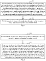
- the embodiment of the disclosure provides a method for transmitting pre-coding indication information at a UE side.
- the method includes the following operations.
- the UE determines first pre-coding indication information and second pre-coding indication information.
- the first pre-coding indication information corresponds to a first-level pre-coding matrix.
- the first-level pre-coding matrix includes beam vectors having different polarizations.
- the second pre-coding indication information corresponds to a second-level pre-coding matrix.
- the second-level pre-coding matrix is configured for weighting amplitudes of and adjusting phases of the beam vectors in the first-level pre-coding matrix.
- the first-level pre-coding matrix and the second-level pre-coding matrix are configured for generation of a pre-coding matrix.
- S12 the UE transmits the first pre-coding indication information and the second pre-coding indication information to a network side device.
- the pre-coding matrix according to the embodiment of the disclosure is a product of the first-level pre-coding matrix and the second-level pre-coding matrix, where the second-level pre-coding matrix is configured to weight amplitudes of and adjust phases of all the beam vectors in the first-level pre-coding matrix.
- a rough orientation of the UE is determined according to the beam vectors in the first-level pre-coding matrix without linear weighting so as to reduce feedback overheads of the system.
- Amplitude weighting and phase adjustment is performed on the beam vectors having different polarizations in the first-level pre-coding matrix through linear weighting according to the second-level pre-coding matrix, so that the beam vectors point to a precise orientation of the UE.
- resolution of the pre-coding matrix can be adjusted flexibly by using the second-level pre-coding matrix to obtain a high-resolution pre-coding matrix and improve the performance of the system.
- the operation S11 of determining, by the UE, the first pre-coding indication information and the second pre-coding indication information includes the following operations: selecting, by the UE, a first-level pre-coding matrix from a set of first-level pre-coding matrixes, and determining the first pre-coding indication information corresponding to the selected first-level pre-coding matrix; and selecting, by the UE, a second-level pre-coding matrix from a set of second-level pre-coding matrixes, and determining the second pre-coding indication information corresponding to the selected second-level pre-coding matrix.
- Each first-level pre-coding matrix is a block diagonal matrix.
- Each non-zero sub-matrix in each first-level pre-coding matrix represents a different polarization.
- Each non-zero sub-matrix includes M beam vectors, and M is a positive integer.
- the first pre-coding indication information is an index of the first-level pre-coding matrix selected by the UE in the set of first-level pre-coding matrixes, where the index is represented as a PMI1.
- the second pre-coding indication information is an index of the second-level pre-coding matrix selected by the UE in the set of second-level pre-coding matrixes, where the index is represented as a PMI2.
- a quantity first-level pre-coding matrixes included by the set of first-level pre-coding matrixes is S.
- Each first-level pre-coding matrix is a block diagonal matrix.
- Each non-zero sub-matrix in each first-level pre-coding matrix represents a different polarization, and each non-zero sub-matrix includes M beam vectors. A part or none of beam vectors in two first-level pre-coding matrixes having adjacent indexes are the same.
- Both S and M are positive integers.
- K 1, 2, ..., K , and K represents a quantity of ports corresponding to each polarization of antennas of the UE.
- Each non-zero sub-matrix (i.e., each block)
- X ( s ) [ V s ⁇ N p V s ⁇ N p +1 ⁇ V s ⁇ N p + M -1 ]
- X ( s ) is a K ⁇ M dimensioned matrix
- B is an M ⁇ M dimensioned diagonal matrix
- N p represents the quantity of different beam vectors among beam vectors in two first-level pre-coding matrixes with adjacent indexes (i.e., the quantity of non-overlapping beam vectors in the two adjacent first-level pre-coding matrixes).
- 1 ⁇ N p ⁇ M, and s 0, 1, 2, ..., S-1.
- B can be a function of X ( s ) , or each element of B can also has a fixed value.
- the index of the m-th beam vector in the s-th first-level pre-coding matrix is mod( s ⁇ N p + m, N -1)-1; where mod( ) represents a mod operation.
- each beam vector in each first-level pre-coding matrix is a Kronecker product of beam vectors in a vertical dimension and beam vectors in a horizontal dimension.
- Each non-zero sub-matrix in each first-level pre-coding matrix is the Kronecker product of M v beam vectors in the vertical dimension and M h beam vectors in the horizontal dimension, where M v and M h are positive integers.
- N v beam vectors are defined in the vertical dimension
- N h beam vectors are defined in the horizontal dimension
- X v V s ⁇ N pv v V s ⁇ N pv + 1 v ⁇ V s ⁇ N pv + M v ⁇ 1 v
- X h V s ′ ⁇ N ph h V s ′ ⁇ N ph + 1 h ⁇ V s ′ ⁇ N ph + M h ⁇ 1 h .
- N pv represents the quantity of non-overlapping beam vectors in adjacent groups in the vertical dimension
- N ph represents the quantity of non-overlapping beam vectors in adjacent groups in the horizontal dimension.
- B is an M vx M v dimensioned diagonal matrix
- D is an M h ⁇ M h dimensioned diagonal matrix.
- B can be a function of X v , or each element of B can also be a fixed value.
- D can be a function of X h , or each element of D can also be a fixed value.
- ⁇ ( ⁇ ) represents phase adjustment factors of two polarizations.
- a l r + and a l r ⁇ are amplitude weighting factors of an l -th beam vector in each polarization of a first-level pre-coding matrix.
- ⁇ l r + and ⁇ l r ⁇ can be any number within a range from - ⁇ to ⁇ .
- l 0, 1, 2, ..., M -1 .
- M represents a quantity of beam vectors in each non-zero sub-matrix in the first-level pre-coding matrix.
- r 1, 2, ..., R.
- R represents a quantity of transmission streams.
- antenna ports of the UE are two-dimension antenna ports
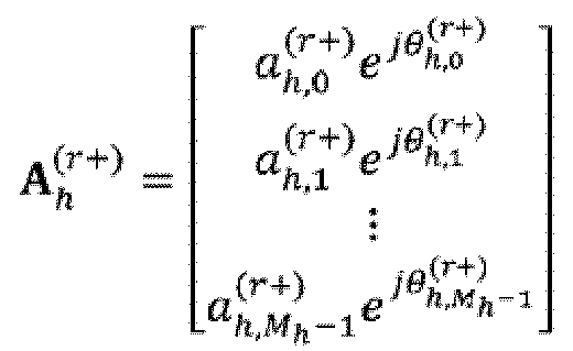
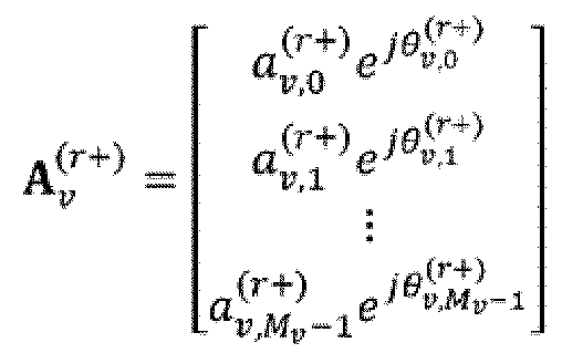
- a v r + a v , 0 r + e j ⁇ v , 0 r + a v , 1 r + e j ⁇ v , 1 r + ⁇ a v , M v ⁇ 1 r + e j ⁇ v , M v ⁇ 1 r + ,
- a v , l v r + and a v , l v r ⁇ represent amplitude weighting factors of an l v -th beam vector in a vertical dimension of each polarization of the first-level pre-coding matrix.
- ⁇ v , l v r + and ⁇ v , l v r ⁇ represent phase adjusting factors of an l v -th beam vector in the vertical dimension of each polarization of the first-level pre-coding matrix.
- Values of ⁇ v , l v r + and ⁇ v , l v r ⁇ can be any numbers within a range from - ⁇ to ⁇ .
- l v 0, 1, 2, ..., M v -1 .
- M v represents a quantity of beam vectors in the vertical dimension.
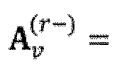
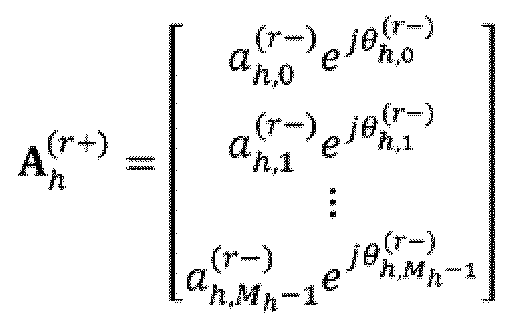
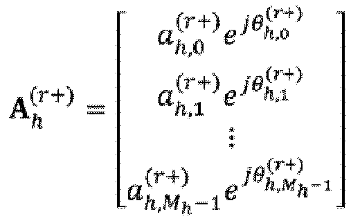
- a h , l h r + and a h , l h r ⁇ represent amplitude weighting factors of an l h -th beam vector in a horizontal dimension of each polarization of the first-level pre-coding matrix.
- ⁇ h , l h r + and ⁇ h , l h r ⁇ represent phase adjusting factors of an l h -th beam vector in the horizontal dimension of each polarization of the first-level pre-coding matrix, and values of ⁇ h , l h r + and ⁇ h , l h r ⁇ can be any numbers within a range from - ⁇ to ⁇ .
- l h 0, 1, 2, ..., M h -1 .
- M h represents a quantity of beam vectors in the horizontal dimension.
- R represents the quantity of transmission streams.
- the embodiment of the disclosure further provides a method for determining a pre-coding matrix at a network side device.
- the method includes the following operations.
- the network side device receives first pre-coding indication information and second pre-coding indication information transmitted by a UE.
- the network side device determines a pre-coding matrix according to the first pre-coding indication information and the second pre-coding indication information.
- the first pre-coding indication information corresponds to a first-level pre-coding matrix.
- the first-level pre-coding matrix includes beam vectors having different polarizations.
- the second pre-coding indication information corresponds to a second-level pre-coding matrix.
- the second-level pre-coding matrix is configured for weighting amplitudes of and adjusting phases of the beam vectors in the first-level pre-coding matrix.
- the first-level pre-coding matrix and the second-level pre-coding matrix are configured for generation of the pre-coding matrix.
- the network side device determines the pre-coding matrix according to the first pre-coding indication information and the second pre-coding indication information in S22 as follows.
- the network side device determines a first-level pre-coding matrix corresponding to the first pre-coding indication information from a set of first-level pre-coding matrixes.
- Each first-level pre-coding matrix is a block diagonal matrix, each non-zero sub-matrix in the first-level pre-coding matrix represents a different polarization, and each non-zero sub-matrix includes M beam vectors. M is a positive integer.
- the network side device determines a second-level pre-coding matrix corresponding to the second pre-coding indication information from a second of first-level pre-coding matrixes. And the network side device uses a matrix composed of functions of the selected first-level pre-coding matrix, direction weighting vectors, and phase adjusting factors as the pre-coding matrix.
- the first pre-coding indication information is an index of the first-level pre-coding matrix selected by the UE in the set of first-level pre-coding matrixes, where the index is represented as a PMI1.
- the second pre-coding indication information is an index of the second-level pre-coding matrix selected by the UE in the set of second-level pre-coding matrixes, where the index is represented as a PMI2.
- ⁇ ( ⁇ ) represents phase adjustment factors of two polarizations.
- a l r + and a l r ⁇ are amplitude weighting factors of an l -th beam vector in each polarization of a first-level pre-coding matrix.
- ⁇ l r + and ⁇ l r ⁇ represent phase adjusting factors of an l -th beam vector in each polarization of the first-level pre-coding matrix.
- Values of ⁇ l r + and ⁇ l r ⁇ can be any number within a range from - ⁇ to ⁇ .
- l 0, 1, 2, ..., M-1.
- M represents a quantity of beam vectors in each non-zero sub-matrix in the first-level pre-coding matrix.
- r 1, 2, ..., R.
- R represents a quantity of transmission streams.
- a v r + a v , 0 r + e j ⁇ v , 0 r + a v , 1 r + e j ⁇ v , 1 r + ⁇ a v , M v ⁇ 1 r + e j ⁇ v , M v ⁇ 1 r + ,
- a v , l v r + and a v , l v r ⁇ represent amplitude weighting factors of an l v -th beam vector in a vertical dimension of each polarization of the first-level pre-coding matrix.
- ⁇ v , l v r + and ⁇ v , l v r ⁇ represent phase adjusting factors of an l v -th beam vector in the vertical dimension of each polarization of the first-level pre-coding matrix.
- Values of ⁇ v , l v r + and ⁇ v , l v r ⁇ can be any numbers within a range from - ⁇ to ⁇ .
- l v 0, 1, 2, ..., M v -1 .
- M v represents a quantity of beam vectors in the vertical dimension.
- a h , l h r + and a h , l h r ⁇ represent amplitude weighting factors of an l h -th beam vector in a horizontal dimension of each polarization of the first-level pre-coding matrix.
- ⁇ h , l h r + and ⁇ h , l h r ⁇ represent phase adjusting factors of an l h -th beam vector in the horizontal dimension of each polarization of the first-level pre-coding matrix, and values of ⁇ h , l h r + and ⁇ h , l h r ⁇ can be any numbers within a range from - ⁇ to ⁇ .
- l h 0, 1, 2, ..., M h -1 .
- M h represents a quantity of beam vectors in the horizontal dimension.
- R represents the quantity of transmission streams.
- the network side device weights amplitudes of and adjust phases of the beam vectors in the first-level pre-coding matrix according to the second-level pre-coding matrix to obtain the final pre-coding matrix W.
- ⁇ ( ⁇ ) represents phase adjustment factors of two polarizations.
- R represents a quantity of transmission streams.
- the operations of the above-mentioned methods can be performed by using a software program.
- the software program can be stored in a storage medium, and when the stored software program is invoked, the above-mentioned operations are performed.
- the embodiment of the disclosure further provides an apparatus for transmitting pre-coding indication information. Since the apparatus addresses the problem by using a principle similar to the principle used by the above-mentioned method for transmitting pre-coding indication information, reference can be made to the implementation of the method for an implementation of the apparatus, and a repeated description thereof is omitted here.
- the embodiment of the disclosure further provides an apparatus for transmitting pre-coding indication information.
- the apparatus includes a determining module 31 configured to determine first pre-coding indication information and second pre-coding indication information and a transmitting module 32 configured to transmit the first pre-coding indication information and the second pre-coding indication information to a network side device.
- the first pre-coding indication information corresponds to a first-level pre-coding matrix.
- the first-level pre-coding matrix includes beam vectors having different polarizations.
- the second pre-coding indication information corresponds to a second-level pre-coding matrix.
- the second-level pre-coding matrix is configured for weighting amplitudes of and adjusting phases of the beam vectors in the first-level pre-coding matrix.
- the first-level pre-coding matrix and the second-level pre-coding matrix are configured for generation of a pre-coding matrix.
- the determining module 31 is further configured to: select a first-level pre-coding matrix from a set of first-level pre-coding matrixes, and determine the first pre-coding indication information corresponding to the selected first-level pre-coding matrix; select a second-level pre-coding matrix from a set of second-level pre-coding matrixes, and determine the second pre-coding indication information corresponding to the selected second-level pre-coding matrix.
- Each first-level pre-coding matrix is a block diagonal matrix.
- Each non-zero sub-matrix in each first-level pre-coding matrix represents a different polarization.
- Each non-zero sub-matrix includes M beam vectors, and M is a positive integer.
- ⁇ ( ⁇ ) represents phase adjustment factors of two polarizations.
- a l r + and a l r ⁇ are amplitude weighting factors of an l -th beam vector in each polarization of a first-level pre-coding matrix.
- ⁇ l r + and ⁇ l r ⁇ represent phase adjusting factors of an l -th beam vector in each polarization of the first-level pre-coding matrix.
- ⁇ l r + and ⁇ l r ⁇ are within a range from - ⁇ to ⁇ .
- l 0, 1, 2, ..., M-1.
- M represents a quantity of beam vectors in each non-zero sub-matrix in the first-level pre-coding matrix.
- r 1, 2, ..., R.
- R represents a quantity of transmission streams.
- a v r + a v , 0 r + e j ⁇ v , 0 r + a v , 1 r + e j ⁇ v , 1 r + ⁇ a v , M v ⁇ 1 r + e j ⁇ v , M v ⁇ 1 r + ,
- a v , l v r + and a v , l v r ⁇ represent amplitude weighting factors of an l v -th beam vector in a vertical dimension of each polarization of the first-level pre-coding matrix.
- ⁇ v , l v r + and ⁇ v , l v r ⁇ represent phase adjusting factors of an l v -th beam vector in the vertical dimension of each polarization of the first-level pre-coding matrix.
- Values of ⁇ v , l v r + and ⁇ v , l v r ⁇ are within a range from - ⁇ to ⁇ .
- l v 0, 1, 2, ..., M v -1.
- M v represents a quantity of beam vectors in the vertical dimension.
- a h , l h r + and a h , l h r ⁇ represent amplitude weighting factors of an l h -th beam vector in a horizontal dimension of each polarization of the first-level pre-coding matrix.
- ⁇ h , l h r + and ⁇ h , l h r ⁇ represent phase adjusting factors of an l h -th beam vector in the horizontal dimension of each polarization of the first-level pre-coding matrix, and values of ⁇ h , l h r + and ⁇ h , l h r ⁇ are within a range from - ⁇ to ⁇ .
- l h 0, 1, 2, ..., M h -1 .
- M h represents a quantity of beam vectors in the horizontal dimension.
- R represents the quantity of transmission streams.
- the embodiment of the disclosure further provides an apparatus for determining a pre-coding matrix. Since the apparatus addresses the problem by using a principle similar to the principle used by the above-mentioned method for determining a pre-coding matrix, reference can be made to the implementation of the method for an implementation of the apparatus, and a repeated description thereof is omitted here.
- the embodiment of the disclosure further provides an apparatus for determining a pre-coding matrix.
- the apparatus includes: a receiving module 41 configured to receive first pre-coding indication information and second pre-coding indication information transmitted by a UE; and a processing module 42 configured to determine the pre-coding matrix according to the first pre-coding indication information and the second pre-coding indication information.
- the first pre-coding indication information corresponds to a first-level pre-coding matrix.
- the first-level pre-coding matrix includes beam vectors having different polarizations.
- the second pre-coding indication information corresponds to a second-level pre-coding matrix.
- the second-level pre-coding matrix is configured for weighting amplitudes of and adjusting phases of the beam vectors in the first-level pre-coding matrix.
- the first-level pre-coding matrix and the second-level pre-coding matrix are configured for generation of the pre-coding matrix.
- the processing module 42 is further configured to: determine a first-level pre-coding matrix corresponding to the first pre-coding indication information from a set of first-level pre-coding matrixes; determine a second-level pre-coding matrix corresponding to the second pre-coding indication information from a set of second-level pre-coding matrixes; and determine the pre-coding matrix by multiplying the determined first-level pre-coding matrix and the determined second level pre-coding matrix.
- Each first-level pre-coding matrix is a block diagonal matrix.
- Each non-zero sub-matrix in each first-level pre-coding matrix represents a different polarization.
- Each non-zero sub-matrix includes M beam vectors, and M is a positive integer.
- ⁇ ( ⁇ ) represents phase adjustment factors of two polarizations.
- a l r + and a l r ⁇ are amplitude weighting factors of an l -th beam vector in each polarization of a first-level pre-coding matrix.
- ⁇ l r + and ⁇ l r ⁇ represent phase adjusting factors of an l -th beam vector in each polarization of the first-level pre-coding matrix.
- ⁇ l r + and ⁇ l r ⁇ are within a range from - ⁇ to ⁇ .
- l 0, 1, 2, ..., M-1.
- M represents a quantity of beam vectors in each non-zero sub-matrix in the first-level pre-coding matrix.
- r 1, 2, ..., R.
- R represents a quantity of transmission streams.
- antenna ports of the UE are two-dimension antenna ports
- a v r + a v , 0 r + e j ⁇ v , 0 r + a v , 1 r + e j ⁇ v , 1 r + ⁇ a v , M v ⁇ 1 r + e j ⁇ v , M v ⁇ 1 r + ,
- a v , l v r + and a v , l v r ⁇ represent amplitude weighting factors of an l v -th beam vector in a vertical dimension of each polarization of the first-level pre-coding matrix.
- ⁇ v , l v r + and ⁇ v , l v r ⁇ represent phase adjusting factors of an l v -th beam vector in the vertical dimension of each polarization of the first-level pre-coding matrix.
- Values of ⁇ v , l v r + and ⁇ v , l v r ⁇ are within a range from - ⁇ to ⁇ .
- l v 0, 1, 2, ..., M v -1.
- M v represents a quantity of beam vectors in the vertical dimension.
- a h , l h r + and a h , l h r ⁇ represent amplitude weighting factors of an l h -th beam vector in a horizontal dimension of each polarization of the first-level pre-coding matrix.
- ⁇ h , l h r + and ⁇ h , l h r ⁇ represent phase adjusting factors of an l h -th beam vector in the horizontal dimension of each polarization of the first-level pre-coding matrix, and values of ⁇ h , l h r + and ⁇ h , l h r ⁇ are within a range from - ⁇ to ⁇ .
- l h 0, 1, 2, ..., M h -1 .
- M h represents a quantity of beam vectors in the horizontal dimension.
- R represents the quantity of transmission streams.
- the UE includes a transceiver 51 and at least one processor 52 connected with the transceiver 51.
- the at least one processor 52 is configured to read a program in a memory 53 to perform the following operation: determining first pre-coding indication information and second pre-coding indication information.
- the first pre-coding indication information corresponds to a first-level pre-coding matrix.
- the first-level pre-coding matrix includes beam vectors having different polarizations.
- the second pre-coding indication information corresponds to a second-level pre-coding matrix.
- the second-level pre-coding matrix is configured for weighting amplitudes of and adjusting phases of the beam vectors in the first-level pre-coding matrix.
- the first-level pre-coding matrix and the second-level pre-coding matrix are configured for generation of a pre-coding matrix.
- the transceiver 51 is configured to be controlled by the at least one processor 52 to transmit the first pre-coding indication information and the second pre-coding indication information to a network side device.
- the bus architecture can include any quantity of interconnected buses and bridges to particularly link together various circuits including one or more processors represented by the at least one processor 52 and one or more memories represented by the memory 53.
- the bus architecture can further link together various other circuits such as a prophetical device, a manostat, a power management circuit, and etc., which are well known in the art, so a further description thereof is omitted in this context.
- the bus interface serves as an interface.
- the transceiver 51 can be a quantity of elements including a transmitter and a receiver, to provide units for communication with various other devices over a transmission medium.
- a user interface 54 can also be an interface via which desirable devices can be connected internally or externally, and the connected devices can include but are not be limited to a keypad, a display, a speaker, a microphone, a joystick, and etc.
- the at least one processor 52 is responsible for managing the bus architecture and performing normal processing, and the memory 53 can store data for use by the at least one processor 52 when performing the operations.
- the at least one processor 52 is further configured to: to perform the following operations: selecting a first-level pre-coding matrix from a set of first-level pre-coding matrixes, and determining the first pre-coding indication information corresponding to the selected first-level pre-coding matrix; selecting a second-level pre-coding matrix from a set of second-level pre-coding matrixes, and determining the second pre-coding indication information corresponding to the selected second-level pre-coding matrix.
- Each first-level pre-coding matrix is a block diagonal matrix.
- Each non-zero sub-matrix in each first-level pre-coding matrix represents a different polarization.
- Each non-zero sub-matrix includes M beam vectors, and M is a positive integer.
- the base station includes a transceiver 61 and at least one processor 62 connected with the transceiver 61.
- the at least one processor 62 is configured to read a program in a memory 63 to perform the following operation: receiving first pre-coding indication information and second pre-coding indication information transmitted by a UE through the transceiver 61; and determining the pre-coding matrix according to the first pre-coding indication information and the second pre-coding indication information.
- the first pre-coding indication information corresponds to a first-level pre-coding matrix.
- the first-level pre-coding matrix includes beam vectors having different polarizations.
- the second pre-coding indication information corresponds to a second-level pre-coding matrix.
- the second-level pre-coding matrix is configured for weighting amplitudes of and adjusting phases of the beam vectors in the first-level pre-coding matrix.
- the first-level pre-coding matrix and the second-level pre-coding matrix are configured for generation of the pre-coding matrix.
- the bus architecture can include any quantity of interconnected buses and bridges to particularly link together various circuits including one or more processors represented by the at least one processor 62 and one or more memories represented by the memory 63.
- the bus architecture can further link together various other circuits such as a prophetical device, a manostat, a power management circuit, and etc., which are well known in the art, so a further description thereof is omitted in this context.
- the bus interface serves as an interface.
- the transceiver 61 can be a quantity of elements including a transmitter and a receiver, to provide units for communication with various other devices over a transmission medium.
- a user interface 64 can also be an interface via which desirable devices can be connected internally or externally, and the connected devices can include but are not be limited to a keypad, a display, a speaker, a microphone, a joystick, and etc.
- the at least one processor 62 is responsible for managing the bus architecture and performing normal processing, and the memory 63 can store data for use by the at least one processor 62 when performing the operations.
- the at least one processor is further configured to perform the following operations: determining a first-level pre-coding matrix corresponding to the first pre-coding indication information from a set of first-level pre-coding matrixes; determining a second-level pre-coding matrix corresponding to the second pre-coding indication information from a set of second-level pre-coding matrixes; and determining the pre-coding matrix by multiplying the determined first-level pre-coding matrix and the determined second level pre-coding matrix.
- Each first-level pre-coding matrix is a block diagonal matrix, each non-zero sub-matrix in each first-level pre-coding matrix represents a different polarization, each non-zero sub-matrix includes M beam vectors, and M is a positive integer.
- the embodiment of the disclosure can be embodied as a method, a system or a computer program product. Therefore the disclosure can be embodied in a form of an all-hardware embodiment, an all-software embodiment or an embodiment of software and hardware in combination. Furthermore the disclosure can be embodied in the form of a computer program product in one or more computer useable storage mediums (including but not limited to a disk memory, a CD-ROM, an optical memory, and etc.) in which computer useable program codes are contained.
- a computer useable storage mediums including but not limited to a disk memory, a CD-ROM, an optical memory, and etc.
- each operation and/or block in the flow charts and/or the block diagrams and combinations of the operations and/or the blocks in the flow charts and/or the block diagrams can be implemented by computer program instructions.
- These computer program instructions can be provided to a processor of a general-purpose computer, a specific-purpose computer, an embedded processor or another programmable data processing device to produce a machine so that the instructions executed by the processor of the computer or the other programmable data processing device create means for performing functions specified in the flow charts and/or the block diagrams.
- These computer program instructions can also be stored into a computer readable memory capable of directing the computer or the other programmable data processing device to operate in a specific manner so that the instructions stored in the computer readable memory create an article of manufacture including an instruction means which performs functions specified in the flow charts and/or the block diagrams.
- These computer program instructions can also be loaded onto the computer or the other programmable data processing device so that a series of operations are performed by the computer or the other programmable data processing device to create a computer implemented process so that the instructions executed by the computer or the other programmable device provide operations for performing the functions specified in the flow chart and/or the block diagrams.
Landscapes
- Engineering & Computer Science (AREA)
- Computer Networks & Wireless Communication (AREA)
- Signal Processing (AREA)
- Physics & Mathematics (AREA)
- Mathematical Physics (AREA)
- Radio Transmission System (AREA)
- Mobile Radio Communication Systems (AREA)
Claims (12)
- Verfahren zum Senden von Vorcodierungsanzeigeinformationen, wobei das Verfahren Folgendes umfasst:Bestimmen (S11) durch ein Anwendergerät, UE, erster Vorcodierungsanzeigeinformationen und zweiter Vorcodierungsanzeigeinformationen, wobei die ersten Vorcodierungsanzeigeinformationen einer Vorcodierungsmatrix einer ersten Stufe entsprechen, die Vorcodierungsmatrix einer ersten Stufe Strahlvektoren, die verschiedene Polarisierungen besitzen, umfasst, die zweiten Vorcodierungsanzeigeinformationen einer Vorcodierungsmatrix einer zweiten Stufe entsprechen, die Vorcodierungsmatrix einer zweiten Stufe für jede Polarisierung der verschiedenen Polarisierungen konfiguriert ist, Amplituden aller Strahlvektoren, die die Polarisierung besitzen, in der Vorcodierungsmatrix einer ersten Stufe zu gewichten und ihre Phasen anzupassen, und die Vorcodierungsmatrix einer ersten Stufe und die Vorcodierungsmatrix einer zweiten Stufe zur Erzeugung einer Vorcodierungsmatrix konfiguriert sind; undSenden (S12) durch das UE der ersten Vorcodierungsanzeigeinformationen und der zweiten Vorcodierungsanzeigeinformationen zu einer netzseitigen Einrichtung; wobeidas Bestimmen (S11) durch das UE der ersten Vorcodierungsanzeigeinformationen und der zweiten Vorcodierungsanzeigeinformationen Folgendes umfasst:Wählen durch das UE einer Vorcodierungsmatrix einer ersten Stufe aus einem Satz von Vorcodierungsmatrizen einer ersten Stufe und Bestimmen der ersten Vorcodierungsanzeigeinformationen, die der gewählten Vorcodierungsmatrix einer ersten Stufe entsprechen, wobei jede Vorcodierungsmatrix einer ersten Stufe eine Blockdiagonalmatrix ist, die Untermatrix ungleich null in jeder Vorcodierungsmatrix einer ersten Stufe jeweils eine verschiedene Polarisierung repräsentiert, die Untermatrix ungleich null jeweils M Strahlvektoren umfasst und M eine positive ganze Zahl ist; undWählen durch das UE einer Vorcodierungsmatrix einer zweiten Stufe aus einem Satz von Vorcodierungsmatrizen einer zweiten Stufe und Bestimmen der zweiten Vorcodierungsanzeigeinformationen, die der gewählten Vorcodierungsmatrix einer zweiten Stufe entsprechen; undjede Vorcodierungsmatrix einer zweiten Stufe, W 2, im Satz von Vorcodierungsmatrizen einer zweiten Stufe repräsentiert ist durch:
 wobei φ (·) Phaseneinstellfaktoren von zwei Polarisierungen repräsentiert;


- Verfahren nach Anspruch 1, wobei Werte von


- Verfahren nach Anspruch 2, wobei Antennenanschlüsse des UE zweidimensionale Antennenanschlüsse sind und jede Vorcodierungsmatrix einer zweiten Stufe W 2 im Satz von Vorcodierungsmatrizen einer zweiten Stufe repräsentiert ist durch:


- Verfahren zum Bestimmen einer Vorcodierungsmatrix, wobei das Verfahren Folgendes umfasst:Empfangen (S21) durch eine netzseitige Einrichtung erster Vorcodierungsanzeigeinformationen und zweiter Vorcodierungsanzeigeinformationen, die durch ein Anwendergerät gesendet, UE, wurden; undBestimmen (S22) durch die netzseitige Einrichtung der Vorcodierungsmatrix gemäß den ersten Vorcodierungsanzeigeinformationen und den zweiten Vorcodierungsanzeigeinformationen; wobeidie ersten Vorcodierungsanzeigeinformationen einer Vorcodierungsmatrix einer ersten Stufe entsprechen, die Vorcodierungsmatrix einer ersten Stufe Strahlvektoren, die verschiedene Polarisierungen besitzen, umfasst, die zweiten Vorcodierungsanzeigeinformationen einer Vorcodierungsmatrix einer zweiten Stufe entsprechen, die Vorcodierungsmatrix einer zweiten Stufe für jede Polarisierung der verschiedenen Polarisierungen konfiguriert ist, Amplituden aller Strahlvektoren, die die Polarisierung besitzen, in der Vorcodierungsmatrix einer ersten Stufe zu gewichten und ihre Phasen anzupassen, und die Vorcodierungsmatrix einer ersten Stufe und die Vorcodierungsmatrix einer zweiten Stufe zur Erzeugung der Vorcodierungsmatrix konfiguriert sind; unddas Bestimmen (S22) durch die netzseitige Einrichtung der Vorcodierungsmatrix Folgendes umfasst:Bestimmen durch die netzseitige Einrichtung einer Vorcodierungsmatrix einer ersten Stufe, die den ersten Vorcodierungsanzeigeinformationen entspricht, aus einem Satz von Vorcodierungsmatrizen einer ersten Stufe, wobei jede Vorcodierungsmatrix einer ersten Stufe eine Blockdiagonalmatrix ist, die Untermatrix ungleich null in jeder Vorcodierungsmatrix einer ersten Stufe jeweils eine verschiedene Polarisierung repräsentiert, die Untermatrix ungleich null jeweils M Strahlvektoren umfasst und M eine positive ganze Zahl ist;Bestimmen durch die netzseitige Einrichtung einer Vorcodierungsmatrix einer zweiten Stufe, die den zweiten Vorcodierungsanzeigeinformationen entspricht, aus einem Satz von Vorcodierungsmatrizen einer zweiten Stufe; undBestimmen durch die netzseitige Einrichtung der Vorcodierungsmatrix durch Multiplizieren der bestimmten Vorcodierungsmatrix einer ersten Stufe und der bestimmten Vorcodierungsmatrix einer zweiten Stufe; wobeijede Vorcodierungsmatrix einer zweiten Stufe, W 2, im Satz von Vorcodierungsmatrizen einer zweiten Stufe repräsentiert ist durch:
 wobei φ (·) Phaseneinstellfaktoren von zwei Polarisierungen repräsentiert;


- Verfahren nach Anspruch 4, wobei Werte von


- Verfahren nach Anspruch 5, wobei Antennenanschlüsse des UE zweidimensionale Antennenanschlüsse sind und jede Vorcodierungsmatrix einer zweiten Stufe W 2 im Satz von Vorcodierungsmatrizen einer zweiten Stufe repräsentiert ist durch:


- Vorrichtung zum Senden von Vorcodierungsanzeigeinformationen, wobei die Vorrichtung Folgendes umfasst:ein Bestimmungsmodul (31), das konfiguriert ist zum Bestimmen erster Vorcodierungsanzeigeinformationen und zweiter Vorcodierungsanzeigeinformationen, wobei die ersten Vorcodierungsanzeigeinformationen einer Vorcodierungsmatrix einer ersten Stufe entsprechen, die Vorcodierungsmatrix einer ersten Stufe Strahlvektoren, die verschiedene Polarisierungen besitzen, umfasst, die zweiten Vorcodierungsanzeigeinformationen einer Vorcodierungsmatrix einer zweiten Stufe entsprechen, die Vorcodierungsmatrix einer zweiten Stufe für jede Polarisierung der verschiedenen Polarisierungen konfiguriert ist, Amplituden aller Strahlvektoren, die die Polarisierung besitzen, in der Vorcodierungsmatrix einer ersten Stufe zu gewichten und ihre Phasen anzupassen, und die Vorcodierungsmatrix einer ersten Stufe und die Vorcodierungsmatrix einer zweiten Stufe zur Erzeugung einer Vorcodierungsmatrix konfiguriert sind; undein Sendemodul (32), das konfiguriert ist zum Senden der ersten Vorcodierungsanzeigeinformationen und der zweiten Vorcodierungsanzeigeinformationen zu einer netzseitigen Einrichtung, wobei das Bestimmungsmodul (31) ferner konfiguriert ist zumWählen einer Vorcodierungsmatrix einer ersten Stufe aus einem Satz von Vorcodierungsmatrizen einer ersten Stufe und Bestimmen der ersten Vorcodierungsanzeigeinformationen, die der gewählten Vorcodierungsmatrix einer ersten Stufe entsprechen, wobei jede Vorcodierungsmatrix einer ersten Stufe eine Blockdiagonalmatrix ist, die Untermatrix ungleich null in jeder Vorcodierungsmatrix einer ersten Stufe jeweils eine verschiedene Polarisierung repräsentiert, die Untermatrix ungleich null jeweils M Strahlvektoren umfasst und M eine positive ganze Zahl ist; undWählen eine Vorcodierungsmatrix einer zweiten Stufe aus einem Satz von Vorcodierungsmatrizen einer zweiten Stufe und Bestimmen der zweiten Vorcodierungsanzeigeinformationen, die der gewählten Vorcodierungsmatrix einer zweiten Stufe entsprechen; wobeijede Vorcodierungsmatrix einer zweiten Stufe, Wa, im Satz von Vorcodierungsmatrizen einer zweiten Stufe repräsentiert ist durch:
 wobei φ (·) Phaseneinstellfaktoren von zwei Polarisierungen repräsentiert;


- Vorrichtung nach Anspruch 7, wobei Werte von


- Vorrichtung nach Anspruch 8, wobei Antennenanschlüsse der Vorrichtung zweidimensionale Antennenanschlüsse sind und jede Vorcodierungsmatrix einer zweiten Stufe W 2 im Satz von Vorcodierungsmatrizen einer zweiten Stufe repräsentiert ist durch:


- Vorrichtung zum Bestimmen einer Vorcodierungsmatrix, wobei die Vorrichtung Folgendes umfasst:ein Empfangsmodul (41), das konfiguriert ist zum Empfangen erster Vorcodierungsanzeigeinformationen und zweiter Vorcodierungsanzeigeinformationen, die durch ein Anwendergerät (UE) gesendet wurden; undein Verarbeitungsmodul (42), das konfiguriert ist zum Bestimmen der Vorcodierungsmatrix gemäß den ersten Vorcodierungsanzeigeinformationen und den zweiten Vorcodierungsanzeigeinformationen; wobeidie ersten Vorcodierungsanzeigeinformationen einer Vorcodierungsmatrix einer ersten Stufe entsprechen, die Vorcodierungsmatrix einer ersten Stufe Strahlvektoren, die verschiedene Polarisierungen besitzen, umfasst, die zweiten Vorcodierungsanzeigeinformationen einer Vorcodierungsmatrix einer zweiten Stufe entsprechen, die Vorcodierungsmatrix einer zweiten Stufe für jede Polarisierung der verschiedenen Polarisierungen konfiguriert ist, Amplituden aller Strahlvektoren, die die Polarisierung besitzen, in der Vorcodierungsmatrix einer ersten Stufe zu gewichten und ihre Phasen anzupassen, und die Vorcodierungsmatrix einer ersten Stufe und die Vorcodierungsmatrix einer zweiten Stufe zur Erzeugung der Vorcodierungsmatrix konfiguriert sind; unddas Verarbeitungsmodul (42) ferner konfiguriert ist zumBestimmen einer Vorcodierungsmatrix einer ersten Stufe, die den ersten Vorcodierungsanzeigeinformationen entspricht, aus einem Satz von Vorcodierungsmatrizen einer ersten Stufe, wobei jede Vorcodierungsmatrix einer ersten Stufe eine Blockdiagonalmatrix ist, die Untermatrix ungleich null in jeder Vorcodierungsmatrix einer ersten Stufe jeweils eine verschiedene Polarisierung repräsentiert, die Untermatrix ungleich null jeweils M Strahlvektoren umfasst und M eine positive ganze Zahl ist;Bestimmen einer Vorcodierungsmatrix einer zweiten Stufe, die den zweiten Vorcodierungsanzeigeinformationen entspricht, aus einem Satz von Vorcodierungsmatrizen einer zweiten Stufe; undBestimmen der Vorcodierungsmatrix durch Multiplizieren der bestimmten Vorcodierungsmatrix einer ersten Stufe und der bestimmten Vorcodierungsmatrix einer zweiten Stufe; wobeijede Vorcodierungsmatrix einer zweiten Stufe, W 2, im Satz von Vorcodierungsmatrizen einer zweiten Stufe repräsentiert ist durch:
 wobei φ (·) Phaseneinstellfaktoren von zwei Polarisierungen repräsentiert;


- Vorrichtung nach Anspruch 10, wobei Werte von


- Vorrichtung nach Anspruch 11, wobei Antennenanschlüsse des UE zweidimensionale Antennenanschlüsse sind und jede Vorcodierungsmatrix einer zweiten Stufe W 2 im Satz von Vorcodierungsmatrizen einer zweiten Stufe repräsentiert ist durch:


Applications Claiming Priority (2)
| Application Number | Priority Date | Filing Date | Title |
|---|---|---|---|
| CN201510524819.2A CN106487435B (zh) | 2015-08-24 | 2015-08-24 | 一种传输编码指示信息和确定预编码矩阵的方法和装置 |
| PCT/CN2016/090079 WO2017032181A1 (zh) | 2015-08-24 | 2016-07-14 | 一种传输编码指示信息和确定预编码矩阵的方法和装置 |
Publications (3)
| Publication Number | Publication Date |
|---|---|
| EP3343791A1 EP3343791A1 (de) | 2018-07-04 |
| EP3343791A4 EP3343791A4 (de) | 2018-08-22 |
| EP3343791B1 true EP3343791B1 (de) | 2022-07-06 |
Family
ID=58099590
Family Applications (1)
| Application Number | Title | Priority Date | Filing Date |
|---|---|---|---|
| EP16838441.0A Active EP3343791B1 (de) | 2015-08-24 | 2016-07-14 | Verfahren und vorrichtungen zur übertragung von codierungsanzeigeinformationen und zur bestimmung einer vorcodierungsmatrix |
Country Status (6)
| Country | Link |
|---|---|
| US (1) | US10879971B2 (de) |
| EP (1) | EP3343791B1 (de) |
| JP (1) | JP6553809B2 (de) |
| KR (1) | KR102127313B1 (de) |
| CN (1) | CN106487435B (de) |
| WO (1) | WO2017032181A1 (de) |
Families Citing this family (9)
| Publication number | Priority date | Publication date | Assignee | Title |
|---|---|---|---|---|
| CN108631837B (zh) * | 2017-03-24 | 2021-06-01 | 华为技术有限公司 | 信息的传输方法和设备 |
| CN109150266A (zh) * | 2017-06-16 | 2019-01-04 | 华为技术有限公司 | 信道状态信息的传输方法、接入网设备和终端设备 |
| CN109560847B (zh) * | 2017-09-26 | 2022-05-13 | 华为技术有限公司 | 信道状态信息反馈和接收方法、发送端设备和接收端设备 |
| WO2019069128A1 (en) * | 2017-10-02 | 2019-04-11 | Lenovo (Singapore) Pte. Ltd. | METHOD AND APPARATUS FOR USING A DETERMINED COMPRESSION MATRIX TO FORM A SET OF COMPOSITE BEAMS |
| US11271696B2 (en) * | 2017-10-10 | 2022-03-08 | Telefonaktiebolaget Lm Ericsson (Publ) | Beam management of a radio transceiver device |
| CN110830092B (zh) * | 2018-08-10 | 2021-10-26 | 华为技术有限公司 | 指示预编码矩阵和确定预编码矩阵的方法以及通信装置 |
| CN111416696B (zh) * | 2019-01-07 | 2023-05-05 | 中国移动通信有限公司研究院 | Pucch的传输方法、装置、相关设备及存储介质 |
| CN115244864A (zh) * | 2020-07-31 | 2022-10-25 | 华为技术有限公司 | 一种预编码方法及装置 |
| KR20230096072A (ko) * | 2020-11-04 | 2023-06-29 | 후아웨이 테크놀러지 컴퍼니 리미티드 | 프리코딩 행렬 지시 방법, 사용자 장비 및 액세스 디바이스 |
Family Cites Families (15)
| Publication number | Priority date | Publication date | Assignee | Title |
|---|---|---|---|---|
| CN100556162C (zh) * | 2007-09-13 | 2009-10-28 | 中兴通讯股份有限公司 | 一种实现明密话切换后媒体流的无损传输方法及系统 |
| PL2369775T3 (pl) * | 2010-03-16 | 2019-08-30 | Lg Electronics Inc. | Sposób i stacja bazowa do przesyłania sygnałów odniesienia oraz sposób i urządzenie użytkownika do odbioru sygnałów odniesienia |
| KR101817724B1 (ko) | 2010-04-30 | 2018-02-21 | 삼성전자주식회사 | 각 리포팅 모드에 대응하는 코드북을 사용하는 다중 입출력 통신 시스템 |
| CN101909022B (zh) * | 2010-06-24 | 2012-12-05 | 北京邮电大学 | 一种时变信道下基于非码本预编码的传输方法 |
| CN102299759B (zh) * | 2010-06-24 | 2013-12-04 | 上海贝尔股份有限公司 | 用于获取预编码矩阵的方法以及装置 |
| WO2012008710A2 (ko) | 2010-07-12 | 2012-01-19 | 엘지전자 주식회사 | 무선 통신 시스템에서 코드북을 이용한 신호 송수신 방법 및 장치 |
| KR101806878B1 (ko) * | 2010-08-16 | 2018-01-10 | 삼성전자주식회사 | 8 개의 전송 안테나들에 대한 코드북 및 그 코드북을 사용하는 통신 시스템 |
| US8781018B2 (en) * | 2011-04-25 | 2014-07-15 | Texas Instruments Incorporated | Six transmit antenna codebook design |
| CN103378882B (zh) * | 2012-04-16 | 2018-04-27 | 中兴通讯股份有限公司 | 一种大规模天线系统控制信号发送方法及装置 |
| CN103780331B (zh) * | 2012-10-19 | 2017-08-18 | 电信科学技术研究院 | 传输编码指示信息和确定预编码矩阵的方法、系统及设备 |
| CN103780332B (zh) * | 2012-10-19 | 2017-03-29 | 电信科学技术研究院 | 传输编码指示信息和确定预编码矩阵的方法、系统及设备 |
| CN103795450B (zh) * | 2012-10-29 | 2017-10-31 | 电信科学技术研究院 | 传输编码指示信息和确定预编码矩阵的方法、系统及设备 |
| EP2950458A4 (de) * | 2013-01-28 | 2016-11-16 | Fujitsu Ltd | Feedbackverfahren für kanalstatusinformationen, verfahren zur übertragung von kanalstatusinformations-referenzsignalen, benutzervorrichtung und basisstation |
| WO2015018030A1 (zh) | 2013-08-08 | 2015-02-12 | 华为技术有限公司 | 确定预编码矩阵指示的方法、接收设备和发送设备 |
| CN105450273B (zh) * | 2015-08-24 | 2016-11-23 | 电信科学技术研究院 | 一种传输编码指示信息和确定预编码矩阵的方法和装置 |
-
2015
- 2015-08-24 CN CN201510524819.2A patent/CN106487435B/zh active Active
-
2016
- 2016-07-14 JP JP2018510787A patent/JP6553809B2/ja active Active
- 2016-07-14 KR KR1020187008551A patent/KR102127313B1/ko active IP Right Grant
- 2016-07-14 WO PCT/CN2016/090079 patent/WO2017032181A1/zh active Application Filing
- 2016-07-14 US US15/754,954 patent/US10879971B2/en active Active
- 2016-07-14 EP EP16838441.0A patent/EP3343791B1/de active Active
Also Published As
| Publication number | Publication date |
|---|---|
| EP3343791A4 (de) | 2018-08-22 |
| EP3343791A1 (de) | 2018-07-04 |
| JP6553809B2 (ja) | 2019-07-31 |
| US10879971B2 (en) | 2020-12-29 |
| WO2017032181A1 (zh) | 2017-03-02 |
| KR20180044388A (ko) | 2018-05-02 |
| CN106487435B (zh) | 2020-03-03 |
| KR102127313B1 (ko) | 2020-06-26 |
| CN106487435A (zh) | 2017-03-08 |
| US20200244322A1 (en) | 2020-07-30 |
| JP2018530947A (ja) | 2018-10-18 |
Similar Documents
| Publication | Publication Date | Title |
|---|---|---|
| EP3343791B1 (de) | Verfahren und vorrichtungen zur übertragung von codierungsanzeigeinformationen und zur bestimmung einer vorcodierungsmatrix | |
| US10567049B2 (en) | Methods and apparatuses for transmitting coding indication information and determining precoding matrix | |
| US11652515B2 (en) | Method and device for feeding back channel state information, and method and device for determining channel state information | |
| US9941942B2 (en) | Method and device for processing channel state information, user equipment and evolved node B | |
| EP3198742B1 (de) | Netzwerkknoten, benutzergerät und verfahren darin zur ermöglichung des benutzergeräts zur bestimmung eines vorcodierer-codebuchs | |
| EP2525505B1 (de) | Verfahren und vorrichtung zur erfassung eines präkodierungsmatrix-indikators (pmi) und präkodierungsmatrix | |
| EP3018852B1 (de) | Verfahren zur bestimmung eines vorcodierungsmatrixindikators, empfangsvorrichtung und übertragungsvorrichtung | |
| EP2913950B1 (de) | Verfahren, system und vorrichtung zur übertragung von codierungsanweisungsinformationen und zur bestimmung einer vorcodierungsmatrix | |
| CN110034797B (zh) | 一种预编码矩阵指示的反馈方法及装置 | |
| KR101819911B1 (ko) | 코드북을 생성하는 방법 | |
| EP3429257A1 (de) | Verfahren zur meldung von kanalstatusinformationen, benutzergerät und basisstation | |
| US20120134434A1 (en) | Method and system for precoding and method for constructing precoding codebook | |
| JPWO2019059406A1 (ja) | Oam多重通信システムおよびモード間干渉除去方法 | |
| CN107733493A (zh) | 用于确定预编码矩阵的方法和装置 | |
| CN107733476B (zh) | 信道状态信息的反馈方法及装置 | |
| KR20210106548A (ko) | 무선통신 네트워크에서 피드백 보고를 위한 방법 및 장치 | |
| EP3007380B1 (de) | Verfahren und vorrichtung zur bestimmung eines vorcodierungsmatrixindikators, benutzervorrichtung und basisstation | |
| JP6556244B2 (ja) | コードブック確定方法及び装置 | |
| CN107113643A (zh) | 一种资源选择的方法及装置和一种电子设备 | |
| EP2913949B1 (de) | Verfahren, system und vorrichtung zur übertragung vorcodierter indikationsinformationen und bestimmung einer vorcodierungsmatrix | |
| CN106685497B (zh) | 码书限制信令的发送、信道信息的量化反馈方法及装置 | |
| EP3383089A1 (de) | Verfahren und system zur erfassung von kanalinformationen | |
| EP2816768B1 (de) | Präzises Cluster mit geringer Komplexität für Strahlenauswahl | |
| JP2018074605A (ja) | プリコーディングマトリクス指標を決定する方法、受信装置、および送信装置 |
Legal Events
| Date | Code | Title | Description |
|---|---|---|---|
| STAA | Information on the status of an ep patent application or granted ep patent |
Free format text: STATUS: THE INTERNATIONAL PUBLICATION HAS BEEN MADE |
|
| PUAI | Public reference made under article 153(3) epc to a published international application that has entered the european phase |
Free format text: ORIGINAL CODE: 0009012 |
|
| STAA | Information on the status of an ep patent application or granted ep patent |
Free format text: STATUS: REQUEST FOR EXAMINATION WAS MADE |
|
| 17P | Request for examination filed |
Effective date: 20180307 |
|
| AK | Designated contracting states |
Kind code of ref document: A1 Designated state(s): AL AT BE BG CH CY CZ DE DK EE ES FI FR GB GR HR HU IE IS IT LI LT LU LV MC MK MT NL NO PL PT RO RS SE SI SK SM TR |
|
| AX | Request for extension of the european patent |
Extension state: BA ME |
|
| A4 | Supplementary search report drawn up and despatched |
Effective date: 20180724 |
|
| RIC1 | Information provided on ipc code assigned before grant |
Ipc: H04B 7/06 20060101ALI20180718BHEP Ipc: H04B 7/04 20170101AFI20180718BHEP |
|
| DAV | Request for validation of the european patent (deleted) | ||
| DAX | Request for extension of the european patent (deleted) | ||
| STAA | Information on the status of an ep patent application or granted ep patent |
Free format text: STATUS: EXAMINATION IS IN PROGRESS |
|
| 17Q | First examination report despatched |
Effective date: 20190705 |
|
| STAA | Information on the status of an ep patent application or granted ep patent |
Free format text: STATUS: EXAMINATION IS IN PROGRESS |
|
| RAP1 | Party data changed (applicant data changed or rights of an application transferred) |
Owner name: DATANG MOBILE COMMUNICATIONS EQUIPMENT CO., LTD. |
|
| GRAP | Despatch of communication of intention to grant a patent |
Free format text: ORIGINAL CODE: EPIDOSNIGR1 |
|
| STAA | Information on the status of an ep patent application or granted ep patent |
Free format text: STATUS: GRANT OF PATENT IS INTENDED |
|
| INTG | Intention to grant announced |
Effective date: 20220202 |
|
| GRAS | Grant fee paid |
Free format text: ORIGINAL CODE: EPIDOSNIGR3 |
|
| GRAA | (expected) grant |
Free format text: ORIGINAL CODE: 0009210 |
|
| STAA | Information on the status of an ep patent application or granted ep patent |
Free format text: STATUS: THE PATENT HAS BEEN GRANTED |
|
| AK | Designated contracting states |
Kind code of ref document: B1 Designated state(s): AL AT BE BG CH CY CZ DE DK EE ES FI FR GB GR HR HU IE IS IT LI LT LU LV MC MK MT NL NO PL PT RO RS SE SI SK SM TR |
|
| REG | Reference to a national code |
Ref country code: AT Ref legal event code: REF Ref document number: 1503623 Country of ref document: AT Kind code of ref document: T Effective date: 20220715 Ref country code: CH Ref legal event code: EP |
|
| REG | Reference to a national code |
Ref country code: DE Ref legal event code: R096 Ref document number: 602016073404 Country of ref document: DE |
|
| REG | Reference to a national code |
Ref country code: IE Ref legal event code: FG4D |
|
| REG | Reference to a national code |
Ref country code: LT Ref legal event code: MG9D |
|
| REG | Reference to a national code |
Ref country code: NL Ref legal event code: MP Effective date: 20220706 |
|
| PG25 | Lapsed in a contracting state [announced via postgrant information from national office to epo] |
Ref country code: SE Free format text: LAPSE BECAUSE OF FAILURE TO SUBMIT A TRANSLATION OF THE DESCRIPTION OR TO PAY THE FEE WITHIN THE PRESCRIBED TIME-LIMIT Effective date: 20220706 Ref country code: RS Free format text: LAPSE BECAUSE OF FAILURE TO SUBMIT A TRANSLATION OF THE DESCRIPTION OR TO PAY THE FEE WITHIN THE PRESCRIBED TIME-LIMIT Effective date: 20220706 Ref country code: PT Free format text: LAPSE BECAUSE OF FAILURE TO SUBMIT A TRANSLATION OF THE DESCRIPTION OR TO PAY THE FEE WITHIN THE PRESCRIBED TIME-LIMIT Effective date: 20221107 Ref country code: NO Free format text: LAPSE BECAUSE OF FAILURE TO SUBMIT A TRANSLATION OF THE DESCRIPTION OR TO PAY THE FEE WITHIN THE PRESCRIBED TIME-LIMIT Effective date: 20221006 Ref country code: NL Free format text: LAPSE BECAUSE OF FAILURE TO SUBMIT A TRANSLATION OF THE DESCRIPTION OR TO PAY THE FEE WITHIN THE PRESCRIBED TIME-LIMIT Effective date: 20220706 Ref country code: LV Free format text: LAPSE BECAUSE OF FAILURE TO SUBMIT A TRANSLATION OF THE DESCRIPTION OR TO PAY THE FEE WITHIN THE PRESCRIBED TIME-LIMIT Effective date: 20220706 Ref country code: LT Free format text: LAPSE BECAUSE OF FAILURE TO SUBMIT A TRANSLATION OF THE DESCRIPTION OR TO PAY THE FEE WITHIN THE PRESCRIBED TIME-LIMIT Effective date: 20220706 Ref country code: FI Free format text: LAPSE BECAUSE OF FAILURE TO SUBMIT A TRANSLATION OF THE DESCRIPTION OR TO PAY THE FEE WITHIN THE PRESCRIBED TIME-LIMIT Effective date: 20220706 Ref country code: ES Free format text: LAPSE BECAUSE OF FAILURE TO SUBMIT A TRANSLATION OF THE DESCRIPTION OR TO PAY THE FEE WITHIN THE PRESCRIBED TIME-LIMIT Effective date: 20220706 |
|
| REG | Reference to a national code |
Ref country code: AT Ref legal event code: MK05 Ref document number: 1503623 Country of ref document: AT Kind code of ref document: T Effective date: 20220706 |
|
| PG25 | Lapsed in a contracting state [announced via postgrant information from national office to epo] |
Ref country code: PL Free format text: LAPSE BECAUSE OF FAILURE TO SUBMIT A TRANSLATION OF THE DESCRIPTION OR TO PAY THE FEE WITHIN THE PRESCRIBED TIME-LIMIT Effective date: 20220706 Ref country code: IS Free format text: LAPSE BECAUSE OF FAILURE TO SUBMIT A TRANSLATION OF THE DESCRIPTION OR TO PAY THE FEE WITHIN THE PRESCRIBED TIME-LIMIT Effective date: 20221106 Ref country code: HR Free format text: LAPSE BECAUSE OF FAILURE TO SUBMIT A TRANSLATION OF THE DESCRIPTION OR TO PAY THE FEE WITHIN THE PRESCRIBED TIME-LIMIT Effective date: 20220706 Ref country code: GR Free format text: LAPSE BECAUSE OF FAILURE TO SUBMIT A TRANSLATION OF THE DESCRIPTION OR TO PAY THE FEE WITHIN THE PRESCRIBED TIME-LIMIT Effective date: 20221007 |
|
| REG | Reference to a national code |
Ref country code: CH Ref legal event code: PL |
|
| REG | Reference to a national code |
Ref country code: BE Ref legal event code: MM Effective date: 20220731 |
|
| REG | Reference to a national code |
Ref country code: DE Ref legal event code: R097 Ref document number: 602016073404 Country of ref document: DE |
|
| PG25 | Lapsed in a contracting state [announced via postgrant information from national office to epo] |
Ref country code: SM Free format text: LAPSE BECAUSE OF FAILURE TO SUBMIT A TRANSLATION OF THE DESCRIPTION OR TO PAY THE FEE WITHIN THE PRESCRIBED TIME-LIMIT Effective date: 20220706 Ref country code: RO Free format text: LAPSE BECAUSE OF FAILURE TO SUBMIT A TRANSLATION OF THE DESCRIPTION OR TO PAY THE FEE WITHIN THE PRESCRIBED TIME-LIMIT Effective date: 20220706 Ref country code: MC Free format text: LAPSE BECAUSE OF FAILURE TO SUBMIT A TRANSLATION OF THE DESCRIPTION OR TO PAY THE FEE WITHIN THE PRESCRIBED TIME-LIMIT Effective date: 20220706 Ref country code: LU Free format text: LAPSE BECAUSE OF NON-PAYMENT OF DUE FEES Effective date: 20220714 Ref country code: LI Free format text: LAPSE BECAUSE OF NON-PAYMENT OF DUE FEES Effective date: 20220731 Ref country code: DK Free format text: LAPSE BECAUSE OF FAILURE TO SUBMIT A TRANSLATION OF THE DESCRIPTION OR TO PAY THE FEE WITHIN THE PRESCRIBED TIME-LIMIT Effective date: 20220706 Ref country code: CZ Free format text: LAPSE BECAUSE OF FAILURE TO SUBMIT A TRANSLATION OF THE DESCRIPTION OR TO PAY THE FEE WITHIN THE PRESCRIBED TIME-LIMIT Effective date: 20220706 Ref country code: CH Free format text: LAPSE BECAUSE OF NON-PAYMENT OF DUE FEES Effective date: 20220731 Ref country code: AT Free format text: LAPSE BECAUSE OF FAILURE TO SUBMIT A TRANSLATION OF THE DESCRIPTION OR TO PAY THE FEE WITHIN THE PRESCRIBED TIME-LIMIT Effective date: 20220706 |
|
| PLBE | No opposition filed within time limit |
Free format text: ORIGINAL CODE: 0009261 |
|
| STAA | Information on the status of an ep patent application or granted ep patent |
Free format text: STATUS: NO OPPOSITION FILED WITHIN TIME LIMIT |
|
| PG25 | Lapsed in a contracting state [announced via postgrant information from national office to epo] |
Ref country code: SK Free format text: LAPSE BECAUSE OF FAILURE TO SUBMIT A TRANSLATION OF THE DESCRIPTION OR TO PAY THE FEE WITHIN THE PRESCRIBED TIME-LIMIT Effective date: 20220706 Ref country code: EE Free format text: LAPSE BECAUSE OF FAILURE TO SUBMIT A TRANSLATION OF THE DESCRIPTION OR TO PAY THE FEE WITHIN THE PRESCRIBED TIME-LIMIT Effective date: 20220706 Ref country code: BE Free format text: LAPSE BECAUSE OF NON-PAYMENT OF DUE FEES Effective date: 20220731 |
|
| 26N | No opposition filed |
Effective date: 20230411 |
|
| P01 | Opt-out of the competence of the unified patent court (upc) registered |
Effective date: 20230512 |
|
| PG25 | Lapsed in a contracting state [announced via postgrant information from national office to epo] |
Ref country code: AL Free format text: LAPSE BECAUSE OF FAILURE TO SUBMIT A TRANSLATION OF THE DESCRIPTION OR TO PAY THE FEE WITHIN THE PRESCRIBED TIME-LIMIT Effective date: 20220706 |
|
| PG25 | Lapsed in a contracting state [announced via postgrant information from national office to epo] |
Ref country code: IE Free format text: LAPSE BECAUSE OF NON-PAYMENT OF DUE FEES Effective date: 20220714 |
|
| PG25 | Lapsed in a contracting state [announced via postgrant information from national office to epo] |
Ref country code: SI Free format text: LAPSE BECAUSE OF FAILURE TO SUBMIT A TRANSLATION OF THE DESCRIPTION OR TO PAY THE FEE WITHIN THE PRESCRIBED TIME-LIMIT Effective date: 20220706 |
|
| PGFP | Annual fee paid to national office [announced via postgrant information from national office to epo] |
Ref country code: GB Payment date: 20230721 Year of fee payment: 8 |
|
| PGFP | Annual fee paid to national office [announced via postgrant information from national office to epo] |
Ref country code: FR Payment date: 20230726 Year of fee payment: 8 Ref country code: DE Payment date: 20230719 Year of fee payment: 8 |
|
| PG25 | Lapsed in a contracting state [announced via postgrant information from national office to epo] |
Ref country code: IT Free format text: LAPSE BECAUSE OF FAILURE TO SUBMIT A TRANSLATION OF THE DESCRIPTION OR TO PAY THE FEE WITHIN THE PRESCRIBED TIME-LIMIT Effective date: 20220706 |
|
| PG25 | Lapsed in a contracting state [announced via postgrant information from national office to epo] |
Ref country code: HU Free format text: LAPSE BECAUSE OF FAILURE TO SUBMIT A TRANSLATION OF THE DESCRIPTION OR TO PAY THE FEE WITHIN THE PRESCRIBED TIME-LIMIT; INVALID AB INITIO Effective date: 20160714 |
|
| PG25 | Lapsed in a contracting state [announced via postgrant information from national office to epo] |
Ref country code: MK Free format text: LAPSE BECAUSE OF FAILURE TO SUBMIT A TRANSLATION OF THE DESCRIPTION OR TO PAY THE FEE WITHIN THE PRESCRIBED TIME-LIMIT Effective date: 20220706 Ref country code: CY Free format text: LAPSE BECAUSE OF FAILURE TO SUBMIT A TRANSLATION OF THE DESCRIPTION OR TO PAY THE FEE WITHIN THE PRESCRIBED TIME-LIMIT Effective date: 20220706 |