EP3342720B1 - Gas replacement system and gas replacement method - Google Patents
Gas replacement system and gas replacement method Download PDFInfo
- Publication number
- EP3342720B1 EP3342720B1 EP16838804.9A EP16838804A EP3342720B1 EP 3342720 B1 EP3342720 B1 EP 3342720B1 EP 16838804 A EP16838804 A EP 16838804A EP 3342720 B1 EP3342720 B1 EP 3342720B1
- Authority
- EP
- European Patent Office
- Prior art keywords
- container
- gas
- chamber
- liquid
- water
- Prior art date
- Legal status (The legal status is an assumption and is not a legal conclusion. Google has not performed a legal analysis and makes no representation as to the accuracy of the status listed.)
- Active
Links
Images


Classifications
-
- B—PERFORMING OPERATIONS; TRANSPORTING
- B65—CONVEYING; PACKING; STORING; HANDLING THIN OR FILAMENTARY MATERIAL
- B65B—MACHINES, APPARATUS OR DEVICES FOR, OR METHODS OF, PACKAGING ARTICLES OR MATERIALS; UNPACKING
- B65B31/00—Packaging articles or materials under special atmospheric or gaseous conditions; Adding propellants to aerosol containers
- B65B31/02—Filling, closing, or filling and closing, containers or wrappers in chambers maintained under vacuum or superatmospheric pressure or containing a special atmosphere, e.g. of inert gas
- B65B31/025—Filling, closing, or filling and closing, containers or wrappers in chambers maintained under vacuum or superatmospheric pressure or containing a special atmosphere, e.g. of inert gas specially adapted for rigid or semi-rigid containers
-
- B—PERFORMING OPERATIONS; TRANSPORTING
- B67—OPENING, CLOSING OR CLEANING BOTTLES, JARS OR SIMILAR CONTAINERS; LIQUID HANDLING
- B67C—CLEANING, FILLING WITH LIQUIDS OR SEMILIQUIDS, OR EMPTYING, OF BOTTLES, JARS, CANS, CASKS, BARRELS, OR SIMILAR CONTAINERS, NOT OTHERWISE PROVIDED FOR; FUNNELS
- B67C3/00—Bottling liquids or semiliquids; Filling jars or cans with liquids or semiliquids using bottling or like apparatus; Filling casks or barrels with liquids or semiliquids
- B67C3/02—Bottling liquids or semiliquids; Filling jars or cans with liquids or semiliquids using bottling or like apparatus
- B67C3/22—Details
- B67C3/222—Head-space air removing devices, e.g. by inducing foam
-
- B—PERFORMING OPERATIONS; TRANSPORTING
- B67—OPENING, CLOSING OR CLEANING BOTTLES, JARS OR SIMILAR CONTAINERS; LIQUID HANDLING
- B67C—CLEANING, FILLING WITH LIQUIDS OR SEMILIQUIDS, OR EMPTYING, OF BOTTLES, JARS, CANS, CASKS, BARRELS, OR SIMILAR CONTAINERS, NOT OTHERWISE PROVIDED FOR; FUNNELS
- B67C3/00—Bottling liquids or semiliquids; Filling jars or cans with liquids or semiliquids using bottling or like apparatus; Filling casks or barrels with liquids or semiliquids
- B67C3/02—Bottling liquids or semiliquids; Filling jars or cans with liquids or semiliquids using bottling or like apparatus
- B67C3/22—Details
- B67C3/225—Means for filling simultaneously, e.g. in a rotary filling apparatus or multiple rows of containers
-
- B—PERFORMING OPERATIONS; TRANSPORTING
- B67—OPENING, CLOSING OR CLEANING BOTTLES, JARS OR SIMILAR CONTAINERS; LIQUID HANDLING
- B67C—CLEANING, FILLING WITH LIQUIDS OR SEMILIQUIDS, OR EMPTYING, OF BOTTLES, JARS, CANS, CASKS, BARRELS, OR SIMILAR CONTAINERS, NOT OTHERWISE PROVIDED FOR; FUNNELS
- B67C3/00—Bottling liquids or semiliquids; Filling jars or cans with liquids or semiliquids using bottling or like apparatus; Filling casks or barrels with liquids or semiliquids
- B67C3/02—Bottling liquids or semiliquids; Filling jars or cans with liquids or semiliquids using bottling or like apparatus
- B67C3/22—Details
- B67C3/24—Devices for supporting or handling bottles
-
- B—PERFORMING OPERATIONS; TRANSPORTING
- B67—OPENING, CLOSING OR CLEANING BOTTLES, JARS OR SIMILAR CONTAINERS; LIQUID HANDLING
- B67C—CLEANING, FILLING WITH LIQUIDS OR SEMILIQUIDS, OR EMPTYING, OF BOTTLES, JARS, CANS, CASKS, BARRELS, OR SIMILAR CONTAINERS, NOT OTHERWISE PROVIDED FOR; FUNNELS
- B67C7/00—Concurrent cleaning, filling, and closing of bottles; Processes or devices for at least two of these operations
- B67C7/0006—Conveying; Synchronising
- B67C7/004—Conveying; Synchronising the containers travelling along a circular path
- B67C7/0046—Infeed and outfeed devices
- B67C7/0053—Infeed and outfeed devices using grippers
-
- B—PERFORMING OPERATIONS; TRANSPORTING
- B67—OPENING, CLOSING OR CLEANING BOTTLES, JARS OR SIMILAR CONTAINERS; LIQUID HANDLING
- B67C—CLEANING, FILLING WITH LIQUIDS OR SEMILIQUIDS, OR EMPTYING, OF BOTTLES, JARS, CANS, CASKS, BARRELS, OR SIMILAR CONTAINERS, NOT OTHERWISE PROVIDED FOR; FUNNELS
- B67C9/00—Devices for emptying bottles, not otherwise provided for
-
- B—PERFORMING OPERATIONS; TRANSPORTING
- B65—CONVEYING; PACKING; STORING; HANDLING THIN OR FILAMENTARY MATERIAL
- B65B—MACHINES, APPARATUS OR DEVICES FOR, OR METHODS OF, PACKAGING ARTICLES OR MATERIALS; UNPACKING
- B65B31/00—Packaging articles or materials under special atmospheric or gaseous conditions; Adding propellants to aerosol containers
- B65B31/04—Evacuating, pressurising or gasifying filled containers or wrappers by means of nozzles through which air or other gas, e.g. an inert gas, is withdrawn or supplied
-
- B—PERFORMING OPERATIONS; TRANSPORTING
- B67—OPENING, CLOSING OR CLEANING BOTTLES, JARS OR SIMILAR CONTAINERS; LIQUID HANDLING
- B67C—CLEANING, FILLING WITH LIQUIDS OR SEMILIQUIDS, OR EMPTYING, OF BOTTLES, JARS, CANS, CASKS, BARRELS, OR SIMILAR CONTAINERS, NOT OTHERWISE PROVIDED FOR; FUNNELS
- B67C3/00—Bottling liquids or semiliquids; Filling jars or cans with liquids or semiliquids using bottling or like apparatus; Filling casks or barrels with liquids or semiliquids
- B67C3/02—Bottling liquids or semiliquids; Filling jars or cans with liquids or semiliquids using bottling or like apparatus
- B67C3/22—Details
- B67C3/26—Filling-heads; Means for engaging filling-heads with bottle necks
- B67C2003/2657—Filling-heads; Means for engaging filling-heads with bottle necks specially adapted for filling cans
-
- B—PERFORMING OPERATIONS; TRANSPORTING
- B67—OPENING, CLOSING OR CLEANING BOTTLES, JARS OR SIMILAR CONTAINERS; LIQUID HANDLING
- B67C—CLEANING, FILLING WITH LIQUIDS OR SEMILIQUIDS, OR EMPTYING, OF BOTTLES, JARS, CANS, CASKS, BARRELS, OR SIMILAR CONTAINERS, NOT OTHERWISE PROVIDED FOR; FUNNELS
- B67C7/00—Concurrent cleaning, filling, and closing of bottles; Processes or devices for at least two of these operations
- B67C7/0006—Conveying; Synchronising
- B67C2007/006—Devices particularly adapted for container filling
-
- B—PERFORMING OPERATIONS; TRANSPORTING
- B67—OPENING, CLOSING OR CLEANING BOTTLES, JARS OR SIMILAR CONTAINERS; LIQUID HANDLING
- B67C—CLEANING, FILLING WITH LIQUIDS OR SEMILIQUIDS, OR EMPTYING, OF BOTTLES, JARS, CANS, CASKS, BARRELS, OR SIMILAR CONTAINERS, NOT OTHERWISE PROVIDED FOR; FUNNELS
- B67C7/00—Concurrent cleaning, filling, and closing of bottles; Processes or devices for at least two of these operations
- B67C7/0006—Conveying; Synchronising
- B67C2007/0066—Devices particularly adapted for container closing
Definitions
- the present invention relates to a gas replacement system that fills a container with a content fluid such as a beverage, seals the container, and replaces contents of the container with a gas, and a gas replacement method.
- non-seal gassing for blowing the carbon dioxide gas into the container without closing an opening of the container to expel the air in the container out of the container may be combined with seal gassing for blowing the carbon dioxide gas from a nozzle of the filling machine into the container after closing the opening of the container with the nozzle to ensure a degassing path in the nozzle.
- seal gassing for blowing the carbon dioxide gas from a nozzle of the filling machine into the container after closing the opening of the container with the nozzle to ensure a degassing path in the nozzle.
- the container filled with the content fluid is transferred to a sealing machine that attaches a lid to seal the container.
- the sealing machine performs undercover gassing for blowing the carbon dioxide gas between the lid and the container and blowing air in a head space that is a space above a fluid level in the container out of container, and then seals the container (for example, WO 2011/151902 A1 ).
- the filling machine and the sealing machine in the conventional beverage manufacturing facility are provided in a room under the atmosphere.
- a more excessive amount of carbon dioxide gas than an amount required for keeping the requested concentration of the oxygen gas that remains in the container below a certain level is supplied from the supply source and used for the gassing. It is preferable to reduce an amount of use of the carbon dioxide gas in terms of cost for the carbon dioxide gas and also of safety in working environment and protection of natural environment.
- the present invention has an object to provide a gas replacement system and a gas replacement method capable of reducing an amount of use of a replacement gas that is required for replacing air in a container and supplied from a supply source.
- a replacement gas leaking from a container during gassing, during snifting in filling with a content fluid, or during transfer from a filling machine to a sealing machine accumulates around the container or a region away from the container in a chamber. If the replacement gas can be collected and blown into the container, an amount of use of the replacement gas supplied from a supply source can be reduced.
- an amount of use of the replacement gas can be also reduced by creating a space having a high concentration of replacement gas in the chamber, and replacing contents of the container with the replacement gas in the space while keeping the concentration of the replacement gas in the space.
- a gas replacement system according to the present invention achieved based on the above idea is a gas replacement system according to claim 1.
- the liquid introduced into the container in the present invention is used as a medium to be replaced with the gas in the chamber containing the replacement gas.
- the container containing the liquid is carried into the chamber containing the replacement gas, and the liquid is discharged from the container in the chamber to replace the contents of the container with the ambient gas contained in the chamber.
- the container carried into the chamber contains no liquid
- the container is filled with the atmosphere, and thus the atmosphere in the container also enters the chamber as the container is carried into the chamber.
- the container containing the liquid is carried, and thus the container can be carried into the chamber without the atmosphere. Specifically, preventing a reduction in the concentration of the replacement gas in the chamber caused by the atmosphere in the container being brought into the chamber allows the contents of the container to be efficiently replaced with the replacement gas in the chamber while keeping the concentration of the replacement gas in the chamber.
- supplying the replacement gas into the chamber to increase the concentration of the replacement gas can make internal pressure of the chamber positive with respect to the atmosphere, thereby preventing entry of foreign matters from outside into the chamber.
- the ambient gas in the chamber containing the replacement gas is introduced into the container.
- the liquid in the container is replaced with the gas in the chamber.
- the concentration of the replacement gas in the container is higher than in the atmosphere.
- the concentration of the replacement gas in the chamber is higher than in the atmosphere, thereby preventing a reduction in the concentration of the replacement gas in the container.
- the replacement gas having leaked around the container before the container is sealed remains in the chamber and is introduced into the container as the liquid in the container supplied into the chamber is discharged.
- the gassing system in the present invention can perform the gassing one or more times at any timing before and after filling with the content fluid. For example, non-seal gassing may be first performed and seal gassing may be then performed.
- the ambient gas in the chamber is introduced into the container along with the discharge of the liquid in the container to increase the concentration of the replacement gas in the container, and then the gassing is performed, thereby reducing an amount of use of the replacement gas supplied from the supply source.
- the replacement gas having once introduced into the container and leaked from the container can be collected in the chamber and again introduced into the container. This can achieve a predetermined concentration of a remaining oxygen gas while significantly reducing the amount of use of the replacement gas supplied from the supply source.
- the inside of the chamber is at positive pressure with respect to the atmosphere by the replacement gas being blown by the gassing system, thereby preventing entry of foreign matters from outside into the chamber.
- the gassing system in the present invention may be such that a gas is supplied in a gas phase from the supply source, or supplied in a liquid phase from the supply source.
- the replacement gas introduced into the container remains in the container, and thus the gas in the container is replaced with the replacement gas.
- a replacement liquid in a liquid phase introduced into the container is vaporized in the container, and thus the gas in the container is replaced with the replacement gas.
- An example of the replacement liquid introduced into the container in the latter case may be nitrogen (N 2 ). If the replacement liquid as the replacement gas in the liquid phase is sprayed or dropped into the container, volume expansion caused by vaporization of the replacement liquid removes the gas in the container out of the container.
- the gas replacement system according to the present invention may include a liquid supply system that introduces the liquid into the container before the container is carried into the chamber.
- the liquid discharge mechanism preferably changes a position of the container to discharge the liquid in the container from an opening of the container under its own weight.
- the gas replacement system according to the present invention includes a washing machine that washes the container with the liquid upstream of the filling machine, and that the washing machine functions as at least one of the liquid discharge mechanism and the liquid supply system that introduces the liquid into the container before the container is carried into the chamber.
- the washing machine functions as the liquid discharge mechanism, and that the chamber covers a position where the liquid is discharged from the container in the washing machine.
- the washing machine includes a gripper capable of changing the position of the container while gripping the container, and that the gripper functions as the liquid discharge mechanism.
- a conveying path along which the container is conveyed in the washing machine includes a twist section constituted by a guide member twisted to change the position of the container while guiding the container, and the twist section functions as the liquid discharge mechanism.
- the gas replacement system according to the present invention includes a liquid supply system that introduces the liquid between the containers at a position where the containers are carried into the chamber.
- a gas replacement method is a method for replacing contents of a container with a gas in filling the container with a content fluid and sealing the container, including the features of claim 10.
- the first step may include washing the container with the liquid and introducing the liquid into the container.
- the first step includes introducing the liquid between the containers adjacent in a conveying direction when the containers are carried into the chamber.
- an amount of use of a replacement gas supplied from a supply source and required for replacing air in a container can be reduced.
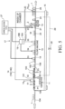
- a gas replacement system 10 shown in Figures 1 and 2 fills a container 1 with a content fluid and seals the container 1 while conveying the container 1 ( Figure 2 ).
- the gas replacement system 10 includes a washing machine 11 (rinser), a filling machine 12 (filler), a sealing machine 13 (seamer), a chamber 14 that covers the filling machine 12 and the sealing machine 13, and a gassing system 17 that introduces a replacement gas into the container 1.
- the replacement gas is efficiently introduced into the container 1 in filling the container 1 with a liquid and sealing the filled container 1.
- the chamber 14 covers the filling machine 12 and the sealing machine 13, and water in the container 1 having been carried into the chamber 14 while containing the water as the liquid is discharged in the chamber 14.
- the water is introduced into the container 1 before the container 1 is carried into the chamber 14.
- the washing machine 11 provided upstream of the filling machine 12 is used to introduce the water into the container 1.
- the chamber 14 covers the filling machine 12 and the sealing machine 13 and also covers a predetermined region of the washing machine 11.
- the chamber 14 contains a continuous space across the predetermined region of the washing machine 11, the filling machine 12, and the sealing machine 13.
- the space inside the chamber 14 is referred to as the inside of the chamber 14.
- a transparent window may be provided in a part of the chamber 14 so as to be able to observe the inside of the chamber 14.
- the chamber 14 includes a partial chamber 141 that covers the filling machine 12 and the sealing machine 13, and a partial chamber 142 that covers the predetermined region of the washing machine 11.
- the insides of the partial chambers 141, 142 communicate with each other.
- Figure 1 shows a border L between the partial chamber 141 and the partial chamber 142 by a dashed line for convenience, there is no need for a wall or the like provided along the border L.
- the washing machine 11 (rotary rinser) includes a rotor 101, and a nozzle 102 ( Figure 2 ) that discharges water toward the container 1 held by the rotor 101.
- the rotor 101 is rotated by a drive unit (not shown).
- the rotor 101 includes grippers 103 ( Figure 2 ) provided on an outer periphery at a certain pitch. Each of the grippers 103 grips the container 1.
- the gripper 103 can rotate around a shaft (not shown) to change a position of the container 1 between an erect position and an inverted position.
- an upstream section A1 is open to the atmosphere, and a downstream section A2 from the section A1 is covered with the partial chamber 142.
- the container 1 is carried into the chamber 14 through an inlet 14IN formed in the partial chamber 142.
- the nozzle 102 feeds water into the container 1.
- the section A2 (hereinafter, a water discharge section), the water in the container 1 is discharged out of the container 1.
- the conveying path of the rotor 101 is divided into the water feed section A1 and the water discharge section A2 at any ratio between the sections A1, A2.
- the division into the water feed section A1 and the water discharge section A2 is made in terms of water feed and water discharge of the container 1, but the container 1 may be washed irrespective of the division.
- nozzles 102 may be arranged in both the sections A1, A2 to wash the container 1 with water discharged from the nozzles 102.
- a conveying device of the washing machine 11 includes a supply conveyor 104 that supplies the container 1 supplied from a pallet of the container (not shown) into the washing machine 11, an inlet star wheel 105 that receives the container 1 from the supply conveyor 104, the rotor 101 described above that receives the container 1 from the inlet star wheel 105, and a star wheel 106 that receives the container 1 from the rotor 101 and transfers the container 1 to the rotor 18 of the filling machine 12.
- Such a configuration of the conveying device is a mere example, and the number and arrangement of star wheels may be determined as appropriate.
- the conveying device of the washing machine 11 is supported by a base 107 provided on a floor of a building.
- a wall 142A of the partial chamber 142 is provided along a diametrical direction of the rotor 101, and a semicircular region in a plan view of the rotor 101 is covered with the partial chamber 142.
- the entire star wheel on the downstream side of the two continuous star wheels may be covered with the partial chamber 142, and the water feed section A1 and the water discharge section A2 may be switched at a position where the container 1 is transferred from the star wheel on the upstream side to the star wheel on the downstream side.
- the nozzle 102 ( Figure 2 ) jets water supplied from a water supply source (not shown) toward the container 1 gripped by the gripper 103.
- nozzles 102 may be arranged on both upper and lower sides of the container 1.
- the water used for washing is not necessarily pure water, but may contain bactericide at a low concentration.
- general tap water is used.
- the water having been jetted from the nozzle 102 and washed the container 1 can be collected through a trough or the like provided below the rotor 101. The same applies to the water discharged from the container 1.
- the nozzle 102 is arranged at least in the water feed section A1 of the water feed section A1 and the water discharge section A2, and also functions as a water supply system (liquid supply system) that introduces water into the container 1.
- a water supply system liquid supply system
- the nozzle 102 introduces water into the container 1 before the container 1 is carried into the water discharge section A2 in the partial chamber 142 along with the rotation of the rotor 101.
- the water jetted downward from the nozzle 102 is supplied into the container 1 under its own weight from the opening 1A of the container 1. It is preferable that an amount of water jetted from the nozzle 102 is appropriately determined so that the water jetted from the nozzle 102 can be efficiently stored in the container 1.
- water is introduced into the container 1 in an erect state (P1), and the position of the container 1 carried into the chamber 14 while containing the water is changed into an inverted state (P2), thereby discharging the water in the container 1.
- the container 1 in this embodiment is a can. Changing the position changes an orientation of an opening 1A ( Figure 4 ) of the container 1.
- the gripper 103 rotates to change the container 1 into the inverted state (P2). Then, the water in the container 1 is discharged from the opening 1A under its own weight. Specifically, the gripper 103 also functions as a water discharge mechanism (liquid discharge mechanism) that discharges the water in the container 1.
- the water After the discharge of the water, typically, with the gripper 103 holding the container 1 in the inverted position (P2'), the water is jetted upward by the nozzle 102 from below the container 1 to wash the container 1. This washing may be omitted.
- the “erect state” herein refers to a state in which the opening 1A is directed straight upward, and also a state in which the opening 1A is directed generally upward.
- the "inverted state” herein refers to a state in which the opening 1A is directed straight downward, and also a state in which the opening 1A is directed generally downward.
- the filling machine 12 includes a rotor 18, and a filling nozzle (not shown) that fills the container 1 held by the rotor 18 with a content fluid.
- the filling nozzle is connected to a liquid phase portion 19A in which the content fluid is stored in a filler bowl 19.
- the container 1 is held in the erect position with the opening 1A upward in a pocket 20 ( Figure 2 ) provided on an outer periphery of the rotor 18 at a certain pitch.
- the rotor 18 is rotated by a drive unit (not shown).
- the sealing machine 13 is a rotary conveying device including a lifter 21, and a lid 2 ( Figure 2 ) is seamed to the container 1 held by the lifter 21 to seal the container 1.
- the conveying device of the gas replacement system 10 includes the rotor 18 and the lifter 21 described above, a transfer star wheel 23 that receives the container 1 from the filling machine 12 and transfers the container 1 to the sealing machine 13, and a discharge star wheel 24 that discharges the container 1 from the sealing machine 13.
- Such a configuration of the conveying device is a mere example, and the number and arrangement of star wheels may be determined as appropriate.
- the conveying device of the gas replacement system 10 is supported by a common base 15 ( Figure 2 ), and the entire gas replacement system 10 is integrally configured.
- the base 15 is provided on the floor of the building.
- the partial chamber 141 that covers the filling machine 12 and the sealing machine 13 is formed into a box shape so as to cover the entire conveying device (the rotor 18, the star wheels 23, 24, the lifter 21) of the gas replacement system 10 arranged together on the base 15, and provided on the base 15.
- the container 1 is carried into the partial chamber 142 with the water introduced in the water feed section A1 of the washing machine 11 being stored in the container 1.
- the star wheel 106 that transfers the container 1 from the washing machine 11 to the filling machine 12 carries the container 1 from the partial chamber 142 into the partial chamber 141.
- the container 1 having been filled and sealed while being conveyed by the rotor 18, the lifter 21, or the like in the partial chamber 141 is discharged out of the partial chamber 141 by the discharge conveyor 26.
- the discharge conveyor 26 extends through inside and outside the partial chamber 141 through an outlet 14OUT formed in the partial chamber 141.
- the container 1 held on the discharge conveyor 26 passes through the outlet 14OUT, and is then transferred to a post-process such as testing, labeling, or packaging.
- the chamber 14 has three openings: the inlet 14IN that receives the container 1, the outlet 14OUT from which the container 1 is discharged, and a lid supply port for carrying the lid 2 into the partial chamber 141.
- the chamber 14 is sealed except for these openings.
- the opening in the chamber 14 may be closed by a flow of a liquid (for example, water) or a gas (for example, air, a replacement gas such as a carbon dioxide gas, a gas in the chamber 14).
- a liquid for example, water
- a gas for example, air, a replacement gas such as a carbon dioxide gas, a gas in the chamber 14.
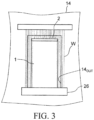
- the outlet 14OUT in the chamber 14 shown in Figure 3 is closed by a curtain-like flow of water W.
- the water W continuously discharged downward from a discharge port located above the container 1 forms the flow of water W along a surface orthogonal to a conveying direction of the container 1 over the entire region of the outlet 14OUT.
- the water W is discharged downward from a plurality of discharge ports arranged in a width direction of the conveyor 25 at intervals, or a slit extending along the width direction.
- the width direction of the conveyor 25 matches a lateral direction in Figure 3 .
- the opening of the container 1 is sealed so that the water does not flow into the container 1.
- a curtain-like airflow may close the outlet 14OUT.
- the inlet 14IN provided in the wall 142A of the partial chamber 142 may be closed by the curtain-like airflow or a curtain-like flow of water W.
- an opening portion 14S (not shown) through which the container 1 passes is provided in a wall 142B that partitions the partial chamber 142 as in the wall 142A.
- the opening portion 14S is also preferably closed by an airflow or a flow of water like the inlet 14IN.
- the container 1 is filled with the content fluid with air existing in the container 1, an oxygen gas contained in the air in the container 1 is mixed in the content fluid, and quality of the content fluid may be impaired by the content fluid coming into contact with the oxygen gas.
- the container 1 is sealed with the air remaining in a head space 1H ( Figure 4 ) above a fluid level, because the oxygen gas comes into contact with the content fluid.
- the gassing system 17 replaces the air in the container 1 with a gas replacement gas inactive to the content fluid, and remove the oxygen gas in the container 1 to a predetermined concentration or less.
- the content fluid is a beer beverage such as beer or law-malt beer
- the oxygen gas tends to impair quality, and there is a strong request to reduce the concentration of the oxygen gas in the container 1.
- a carbon dioxide gas (CO 2 ) is typically used as the replacement gas, but a nitrogen gas (N 2 ) or water vapor (H 2 O) may be used.
- the air in the head space is replaced with the nitrogen gas for preventing oxidation of a non-gas beverage, or the air is replaced with water vapor or a mixture of the nitrogen gas and the water vapor when a can container is filled with a non-gas beverage.
- the carbon dioxide gas is used as the replacement gas.
- the gas replacement system 10 includes a tank 27 filled with a liquid-phase carbon dioxide, that is, a liquefied carbon dioxide gas as a supply source of the carbon dioxide gas.
- a liquid-phase carbon dioxide that is, a liquefied carbon dioxide gas as a supply source of the carbon dioxide gas.
- the carbon dioxide gas supplied from the tank 27 through the filler bowl 19 is blown into the container 1 by the gassing system 17.
- the tank 27 is connected to a gas-phase portion 19B in the filler bowl 19, and the liquefied carbon dioxide gas turns into a gas-phase carbon dioxide gas when being introduced into the gas-phase portion 19B.
- the gassing system 17 ( Figure 2 ) includes a blowing nozzle that blows the carbon dioxide gas supplied from the tank 27, and a valve that opens/closes a flow path of the blowing nozzle.
- the nozzle and the valve are not shown.
- the nozzle and the valve are provided integrally with a filling nozzle of the filling machine 12.
- a counter process for pressurizing the inside of the container 1 when filling, and a snifting process for discharging air to reduce pressure in the container 1 when drawing the filling nozzle out of the liquid are performed. Paths and valves required for these processes may be provided integrally with the filling nozzle.
- the gassing system 17 sequentially performs non-seal gassing and seal gassing.
- the non-seal gassing is performed without the opening of the container 1 being closed, and the seal gassing is performed with the opening of the container 1 being closed by the filling nozzle of the filling machine 12.
- the non-seal gassing rapidly reduces the concentration of the oxygen gas in the container 1, and then the seal gassing more sufficiently reduces the concentration of the oxygen gas in the container 1, thereby allowing the contents of the container 1 to be efficiently replaced with the carbon dioxide gas.
- undercover gassing is performed for blowing the carbon dioxide gas between the lid 2 and the container 1 and replacing the gas in the head space 1H in the container 1 with the carbon dioxide gas.
- the non-seal gassing, the seal gassing, and the undercover gassing may be selectively performed by the gassing system 17 depending on types of the fluid.
- a configuration of piping of the gassing system 17 may be determined as appropriate.
- the carbon dioxide gas introduced into the container 1 by the gassing system 17 leaks from the container 1, for example, while the container 1 is transferred from the filling machine 12 to the sealing machine 13. Since the leaking carbon dioxide gas remains in the chamber 14, an ambient gas in the chamber 14 contains a higher concentration of carbon dioxide gas than the atmosphere. The concentration increases with increasing duration of an operation of the gas replacement system 10.
- the gas replacement system 10 has a main feature that the container 1 containing water is carried into the chamber 14, the water in the container 1 is discharged in the chamber 14, and thus the contents of the container 1 are replaced with the ambient gas in the chamber 14 containing a higher concentration of carbon dioxide gas than the atmosphere.
- gassing by the gassing system 17 is performed in the chamber 14 after the discharge of the water in the container 1.
- the water in the container 1 cannot be discharged after the filling nozzle seals the opening 1A of the container 1. However, the water in the container 1 needs to be discharged before the container 1 is filled with the content fluid so that the water is not mixed in the content fluid.
- the water in the container 1 carried into the chamber 14 is discharged before a first process (in this embodiment, non-seal gassing) by the gassing system 17.
- the ambient gas containing the carbon dioxide gas having leaked from the container 1 and remaining in the chamber 14 is introduced into the container 1 before the carbon dioxide gas is introduced by the gassing system 17.
- the container 1 supplied to the washing machine 11 starts to be washed with water jetted from the nozzle 102 while being gripped in the erect state P1 by the gripper 103, and simultaneously, water is supplied from the nozzle 102 into the container 1 until the container 1 is full of water (step S1: water supply).
- step S1 water supply
- step S2 water discharge
- the water in the container 1 is replaced with the ambient gas in the chamber 14.
- the carbon dioxide gas (CO 2 ) contained in the ambient gas is introduced into the container 1 (see dashed arrows in Figure 4 ).
- the gripper 103 In preparation for filling with the content fluid performed thereafter, the gripper 103 is used to return the position of the container 1 to an erect state P3.
- the ambient gas in the chamber 14 contains a gas other than the carbon dioxide gas, for example, oxygen, but continuing the operation of the gas replacement system 10 gradually increases the concentration of the carbon dioxide gas.
- the container 1 in the full water state is carried into the chamber 14 filled with the ambient gas containing a higher concentration of carbon dioxide gas than the atmosphere, and the water is discharged in the chamber 14 to replace the contents of the container 1 with the ambient gas contained in the chamber 14.
- the atmosphere in the container 1 is also brought into the chamber 14 together with the container 1.
- an amount of the atmosphere, that is, oxygen brought into the chamber 14 as the container 1 is carried can be significantly reduced, thereby preventing a reduction in the concentration of the carbon dioxide gas in the chamber 14.
- the contents of the container 1 can be efficiently replaced with the carbon dioxide gas in the chamber 14 while keeping the concentration of the carbon dioxide gas in the chamber 14.
- the filling machine 12 performs a process described below.
- the gassing system 17 blows the carbon dioxide gas as the replacement gas supplied from the tank 27 into the container 1 without the opening being closed, the container 1 being held by the filling machine 12 (step S3: non-seal gassing).
- a flow of the carbon dioxide gas blown causes the gas in the container 1 to leak from the opening of the container 1, and also causes a part of the carbon dioxide gas blown to leak from the opening of the container 1.
- the non-seal gassing rapidly replaces the gas in the container 1 with the carbon dioxide gas to increase the concentration of the carbon dioxide gas in the container 1.
- step S4 seal gassing
- the seal gassing further advances the replacement of the gas in the container 1 with the carbon dioxide gas, and the oxygen gas in the container 1 is more sufficiently removed.
- step S5 filling with the content fluid
- the carbon dioxide gas of a volume equivalent to a volume of the content fluid returns to the gas-phase portion 19B in the filler bowl 19, but the carbon dioxide gas by an amount for snifting in the head space 1H leaks through the degassing path in the filling nozzle into the chamber 14. Thus, the carbon dioxide gas in the container 1 is replaced with the content fluid.
- the container 1 filled with the content fluid is transferred from the rotor 18 of the filling machine 12 via the transfer star wheel 23 to the lifter 21 of the sealing machine 13 (step S6: transfer to the sealing machine).
- the carbon dioxide gas in the head space 1H in the container 1 leaks from the opening of the container 1 while the container 1 is transferred from the filling machine 12 to the sealing machine 13, the carbon dioxide gas in the head space 1H by an amount for leakage is replaced with the ambient gas in the chamber 14.
- the example in Figure 4 shows that the leakage during the transfer somewhat reduces the concentration of the carbon dioxide gas in the container 1.
- the ambient gas contains a higher concentration of carbon dioxide gas than the atmosphere.
- the chamber 14 Due to the carbon dioxide gas leaking from the container 1, the chamber 14 contains a higher concentration of carbon dioxide gas than the atmosphere, thereby preventing a reduction in the concentration of the carbon dioxide gas in the head space 1H caused by the leakage from the container 1. Thus, the container 1 is supplied to the sealing machine 13 with the concentration of the carbon dioxide gas remaining in the container 1.
- the sealing machine 13 performs a process described below.
- step S7 undercover gassing
- step S8 seaming
- the carbon dioxide gas leaking into the chamber 14 includes, for example, an excess of the carbon dioxide gas blown into the container 1 and flowing out of the container 1 in the non-seal gassing (step S3), or a gas discharged from the degassing path in the seal gassing (step S4).
- step S5 The carbon dioxide gas introduced into the container 1 by the non-seal gassing and the seal gassing leaks into the chamber 14 in the snifting process in filling (step S5) or the transfer (step S6). Then, in the undercover gassing (step S7), much of the carbon dioxide gas blown leaks into the chamber 14.
- a region containing a high concentration of carbon dioxide gas is formed around the conveying path of the container 1 in the gas replacement system 10, and the carbon dioxide gas remains in the chamber 14.
- the ambient gas containing the carbon dioxide gas having leaked from the container 1 and remaining in the chamber 14 is introduced into the container 1 as the water in the container 1 is discharged in the chamber 14 (step S2).
- the container 1 contains a higher concentration of carbon dioxide gas than the atmosphere, and accordingly, by an increment of the concentration of the carbon dioxide gas, an amount of the carbon dioxide gas supplied from the tank 27 can be reduced in next steps S3 and S4 of gassing. Specifically, in steps S3 and S4, a carbon dioxide gas by an amount for a shortage for obtaining the predetermined concentration of the carbon dioxide gas in the container 1 may be introduced into the container 1.
- the concentration of the carbon dioxide gas in the chamber 14 is higher than in the atmosphere, and thus the concentration of the carbon dioxide gas is high in the head space 1H.
- the amount of use of the carbon dioxide gas by the gassing system 17 can be reduced in step S7 of the undercover gassing.
- the amount of use of the carbon dioxide gas supplied from the tank 27 can be significantly reduced, and also the contents of the container 1 can be efficiently replaced to sufficiently reduce the concentration of the oxygen gas in the space and the content fluid in the container 1.
- the reduction in the amount of use of the carbon dioxide gas can reduce manufacturing cost, and contribute to safety in working environment and protection of natural environment.
- the gassing system 17 blows the gas in the chamber 14 substantially sealed, and thus the inside of the chamber 14 is at positive pressure with respect to the outside of the chamber 14 under the atmospheric pressure, thereby preventing foreign matters such as dust or insects from entering the chamber 14 from outside.
- the chamber 14 may cover only the conveying path of the container 1 and therearound in the processes from the discharge of the water in the container 1 through the processing by the gassing system 17 to the sealing of the container 1.
- the position where the water in the container 1 is discharged by the gripper 103 in the washing machine 11 is included in the region covered with the chamber 14.
- the gripper 103 as the water discharge mechanism may be included in the rotor of the filling machine 12. In that case, the chamber 14 may cover only the filling machine 12 and the sealing machine 13.
- a gas containing a relatively high concentration of carbon dioxide gas in the chamber 14 is preferably sucked by a blower 28 into a flow path 29 and supplied near the position where the water in the container 1 is discharged. This can increase a rate of replacement of the contents of the container 1 with the carbon dioxide gas.
- the chamber 14 may be partitioned by a wall, and by a difference in pressure between opposite sides of the wall, the gas containing a high concentration of carbon dioxide gas may be supplied near the position where the water in the container 1 is discharged.
- the wall may be provided, for example, in the position of the border L in Figure 1 . Pressure on a downstream side of the wall is relatively high due to leakage of the carbon dioxide gas from the container 1, and pressure on an upstream side of the wall is relatively low.
- the gas containing a high concentration of carbon dioxide gas can be efficiently fed into the container 1 before the gassing.
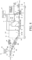
- the container 1 containing water is supplied to a washing machine 40 (roll-through rinser) to discharge water.
- a gas replacement system 30 includes a water supply system 50 ( Figure 7 ), the washing machine 40, the filling machine 12, the sealing machine 13, the chamber 14, and the gassing system 17.
- the water supply system 50 includes a water supply source 51, and a water supply nozzle 52 that feeds water supplied from the water supply source 51 into the container 1.
- a transfer conveyor 33 transfers the container 1 from the filling machine 12 to the sealing machine 13.
- the washing machine 40 includes a frame 401 (a conveying path of the container) constituted by a plurality of metal guide bars (round bars), and a nozzle 402 ( Figure 7 ) that jets water, and showers the container 1 with water from the nozzle 402 while rolling the container 1 under its own weight in the frame 401.
- a frame 401 a conveying path of the container
- metal guide bars round bars
- a nozzle 402 Figure 7
- the guide bars that constitute the frame 401 extend gradually downward from top to bottom.
- the frame 401 includes a twist section TW where the guide bars are twisted.
- the container 1 runs through the twist section TW, and thus a position of the container 1 is inverted.
- the twist sections TW are arranged on upstream and downstream sides, respectively, of the frame 401.
- a region from the upstream twist section TW to the downstream twist section TW is covered with a washing chamber 403.
- An inside of the washing chamber 403 communicates with an inside of the partial chamber 141 that covers the filling machine 12 and the sealing machine 13.
- the washing chamber 403 and the partial chamber 141 constitute the chamber 14 that contains a continuous space.
- the inlet 14IN that receives the container 1 into the chamber 14 is provided in the washing chamber 403.
- the chamber 14 may be constituted by appropriately divided parts.
- the washing chamber 403, a partial chamber that covers the rotor 18 and the star wheel 106 of the filling machine 12, a partial chamber that covers the transfer conveyor 33, and a partial chamber that covers the lifter 21 and the discharge star wheel 24 of the sealing machine 13 may constitute the chamber 14.
- the container 1 is supplied with water into a full water state by the water supply nozzle 52 of the water supply system 50 while being conveyed in the erect state P1 by the supply conveyor 104 (step S1: water supply).
- step S2 water discharge
- the upstream twist section TW functions as a water discharge mechanism.
- the container 1 In order to discharge water in the container 1 having a larger opening 1A than a bottle or the like, the container 1 need only be tipped over sideways rather than be inverted.
- the contents of the container 1 is replaced with the ambient gas in the chamber 14 containing the carbon dioxide gas.
- the container 1 still in the inverted state is washed with water jetted from the nozzle 402 while rolling down in the frame 401. At this time, even if the washing water enters the container 1, the washing water is immediately discharged under its own weight.
- the nozzles 402 may be arranged on both a side of the opening 1A and a bottom side of the container 1.
- the container 1 is returned to the erect state P3 in the downstream twist section TW, and then transferred to the conveyor 25 that conveys the container 1 toward the filling machine 12.
- the second embodiment like the first embodiment, almost all of the carbon dioxide gas having leaked from the container 1 remains in the chamber 14, the water in the container 1 carried into the chamber 14 while containing the water is discharged, and then the processing by the gassing system 17 is performed.
- the amount of use of the carbon dioxide gas can be significantly reduced, and also the contents of the container 1 can be efficiently replaced to sufficiently reduce the concentration of the oxygen gas in the space and the content fluid in the container 1.
- Supplying water into the container 1 and discharging the water in the container 1 to introduce the ambient gas in the chamber 14 into the container 1 is performed on the condition that the concentration of the carbon dioxide gas in the chamber 14 is higher than in the atmosphere.
- the water supply into the container 1 by the water supply system 50 is preferably started after the gas in the chamber 14 reaches a predetermined concentration of the carbon dioxide gas.
- the container 1 may be washed by the water supply into the container 1 and the water discharge from the container 1, and the washing step of showering the container 1 while rolling in the frame 401 with the water from the nozzle 402 may be omitted.
- an intermediate section between the upstream twist section TW and the downstream twist section TW of the frame 401 may be eliminated so that the upstream twist section TW directly connects to the downstream twist section TW.
- a roll-through type washing machine as in the second embodiment may be used for washing the container 1 and also supplying water into the container 1 like the washing machine 11 in the first embodiment, and the water supply system 50 that feeds the water into the container 1 may be eliminated.
- twist section TW and the nozzle 402 are arranged in appropriate positions so that the water can be supplied from the nozzle 402 into the container 1 in the erect state. Then, a position where the water is supplied into the container 1 is open to the atmosphere without being covered with the chamber 14, and after the container 1 containing the water is carried into the chamber 14, the water is discharged in the twist section TW in the chamber 14.
- the contents of the container 1 is replaced with the gas containing the carbon dioxide gas in the washing chamber 403 by an amount of the water discharged, thereby contributing a reduction in the amount of use of the carbon dioxide gas.
- water is introduced between the containers 1, 1 at a position where the container 1 is carried into the chamber 14.
- the inlet 14IN in the chamber 14 corresponds to the position where the container 1 is carried into the chamber 14.
- water in a curtain shape is discharged from a water supply nozzle 53 provided in the water supply system 50 at a position of the inlet 14IN through which the supply conveyor 104 extends.
- the water supply nozzles 53 include upper nozzles that discharge water from top into the container 1, and lateral nozzles that discharge water in a direction orthogonal to a conveying direction toward a gap between the containers 1 arranged on the supply conveyor 104.
- the nozzles form a curtain-like flow of water 53F.
- step S1 water supply
- air in the container 1 is replaced with the water
- air between the containers 1, 1 is also replaced with the water.
- the amount of air entering the chamber 14 can be reduced as compared to the case where an empty container 1 containing no water is carried into the chamber 14.
- the amount of air entering the chamber 14 can be further reduced.
- step S2 water discharge.
- the water introduced between the containers 1, 1 flows out from between the containers 1,1 immediately after the container 1 is carried into the chamber 14 because no bank or the like that keeps the water between the containers 1, 1 is provided there.
- a degree of sealing in the chamber 14 is increased, and this allows the ambient gas, in particular, the carbon dioxide in the chamber 14 to be used without any waste, and allows the inside of the chamber 14 to be reliably kept at positive pressure to prevent entry of foreign matters.
- the water supply nozzle 53 only the upper nozzle that discharges water from above the container 1 toward the container 1 may be provided like the water supply nozzle 52 in the second embodiment ( Figure 7 ), but a combination of the upper nozzle and the lateral nozzle that jets water in the direction orthogonal to the conveying direction allows the water to be more reliably introduced between the containers 1, 1.
- the set of nozzles that discharges the water in the curtain shape may be arranged upstream of the inlet 14IN in the chamber 14 in addition to the position of the inlet 14IN.
- the water introduced between the containers 1, 1 is not kept between the containers 1, 1 but flows out from between the containers 1, 1.
- the water needs to be introduced between the containers 1, 1 by the nozzle at the position of the inlet 14IN.
- the flow of water 53F can be also formed by the water supply nozzle 53 at the position of the inlet 14IN in the partial chamber 142 that covers the predetermined region of the washing machine 11 in the first embodiment. This can provide the same advantage as the third embodiment.
- the gas replacement systems according to the first to third embodiments described above all introduces the carbon dioxide gas into the container 1 by the gassing system 17 in the chamber 14, but the processing by the gassing system 17 is not essential in the present invention.
- the container 1 containing water is carried into the chamber 14 and the water is discharged from the container 1 in the chamber 14. This alone allows the contents of the container 1 to be efficiently replaced with the carbon dioxide gas in the chamber 14 while keeping the concentration of the carbon dioxide gas in the chamber 14.
- the present invention encompasses a configuration in which the gassing system 17 is eliminated from the gas replacement system according to the first to third embodiments.
- the present invention encompasses a gas replacement system including: a filling machine 12 that fills a container 1 with a content fluid; a sealing machine 13 that seals the container 1 transferred from the filling machine 12; a chamber 14 that covers the filling machine 12 and the sealing machine 13 and contains a replacement gas; and a liquid discharge mechanism that discharges water in the container 1 carried into the chamber 14 while containing the water out of the container 1 in the chamber 14.
- the chamber 14 may contain an ambient gas having a higher concentration of N 2 gas than the atmosphere, the container 1 containing the water is carried into the chamber 14, and the water is discharged in the chamber 14.
- the contents of the container 1 is replaced with the ambient gas in the chamber 14 containing the N 2 gas, and then the container 1 can be filled with the content fluid without the gassing.
- the container in the present invention is not limited a can, but may be a PET bottle or a glass bottle. Such containers are sealed by respective appropriate methods.
- the lid for sealing the container that is, a packaging material for sealing the container 1 includes a can lid, also a bottle cap, or a film that seals an opening portion of a container body.
- water is representative of a liquid as a medium in the container 1 to be replaced with the ambient gas in the chamber 14 as the liquid is discharged from the container 1 in the chamber 14, but other liquids may be used.
- a content fluid having a lower concentration than a defined concentration may be introduced into the container 1 and discharged in the chamber 14.
- the gas replacement system and the gas replacement method according to the present invention for introducing the replacement gas into the container 1 for quality preservation of the filled content fluid may be appropriately configured as long as the liquid in the container 1 carried into the chamber 14 while containing the liquid is discharged in the chamber 14 and then gassing is performed.
- Such a system may not necessarily include a washing device that washes the container 1, and such a method does not necessarily require a washing step of the container 1.
- the configuration of the washing machine 11 or 40 provided as an upstream step of the filling machine 12 may be used to easily achieve the liquid discharge mechanism and the liquid supply system in the present invention, and cost of the gas replacement system can be reduced because of a few additional elements.
- the rotary rinser (first embodiment) and the roll-through rinser (second embodiment) are taken, but besides, a grip rinser or a bottle washing machine, or the like may be used.
- the grip rinser includes a conveying path that conveys the container 1 while holding the container 1 from opposite sides by a rubber belt.
- the conveying path includes a first section and a second section in which the position of the container is inverted with the container being held by the rubber belt wound around a rotor that rotates around a horizontal axis.
- washing water is fed from a nozzle into the container conveyed in the erect state, and the water in container can be discharged along with the inversion of the container in the first section. Then, the container is again inverted in the second section and returned to the erect state, and discharged toward a filling step.
- the bottle washing machine used for a beer bottle or the like washes a container by placing a bottle in bottle gages arranged in a plurality of rows and immersing the bottle gages in a washing liquid. After the washing, rotation of the bottle gage inverts the bottle to discharge the washing liquid in the bottle. Then, the bottle is returned to the erect state and discharged toward the filling step.
- an appropriate washing machine may be used depending on types of the containers.
- the container 1 may be washed by the water supply (water feed) into the container 1 and the water discharge.
- the container 1 may be washed at appropriate timing as required.
- the water supply system 50 may supply water into the container 1, and then the washing machine 40 may discharge the water while washing the container 1, or the water may be supplied into the container 1 after washing of the container 1 and then discharged.
- the washing water may be supplied into a remaining space in the container 1.
- the water is stored in the container 1 from the washing step to the water supply step.
- the water may be discharged after the water supply into the container 1, and then the container 1 may be washed.
- the container 1 needs not be washed in the chamber 14. In the present invention, it is important that the water supplied into the container 1 before the container 1 is carried into the chamber 14 is discharged in the chamber 14.
- “Supplying water into the container before the container is carried” encompasses supplying water at the same time as the container 1 is carried into the chamber 14 as in the third embodiment.
- the container 1 it is not essential to change the position of the container 1 for the water supply and the water discharge.
- the water in the container 1 conveyed in the erect state by the conveyor may be sucked by a nozzle to be discharged out of the container 1.
- the position of the container 1 is the erect state in the water supply.
- the container 1 may be carried into the chamber 14 while the opening 1A of the container 1 into which the water is introduced in the inverted state is closed by an appropriate member, and the opening 1A may be opened in the chamber 14 to discharge the water in the container 1.
- the content fluid that fills the container 1 may include, not limited to beer or beer beverages, all kinds of alcohol and beverages such as Japanese sake, foreign liquors, coffee beverages, fruit juice beverages, tea beverages.
- the present invention is applicable to such alcohol and beverages of which oxidation should be avoided.
- liquid filling the container is not limited to beverages, but may be any liquid that needs quality preservation by use of a replacement gas.
Landscapes
- Chemical & Material Sciences (AREA)
- Dispersion Chemistry (AREA)
- Engineering & Computer Science (AREA)
- Mechanical Engineering (AREA)
- Filling Of Jars Or Cans And Processes For Cleaning And Sealing Jars (AREA)
- Vacuum Packaging (AREA)
Applications Claiming Priority (2)
| Application Number | Priority Date | Filing Date | Title |
|---|---|---|---|
| JP2015165232A JP6534315B2 (ja) | 2015-08-24 | 2015-08-24 | ガス置換システムおよびガス置換方法 |
| PCT/JP2016/003809 WO2017033454A1 (ja) | 2015-08-24 | 2016-08-22 | ガス置換システムおよびガス置換方法 |
Publications (3)
| Publication Number | Publication Date |
|---|---|
| EP3342720A1 EP3342720A1 (en) | 2018-07-04 |
| EP3342720A4 EP3342720A4 (en) | 2019-04-10 |
| EP3342720B1 true EP3342720B1 (en) | 2025-04-30 |
Family
ID=58099715
Family Applications (1)
| Application Number | Title | Priority Date | Filing Date |
|---|---|---|---|
| EP16838804.9A Active EP3342720B1 (en) | 2015-08-24 | 2016-08-22 | Gas replacement system and gas replacement method |
Country Status (6)
| Country | Link |
|---|---|
| US (1) | US11180357B2 (enExample) |
| EP (1) | EP3342720B1 (enExample) |
| JP (1) | JP6534315B2 (enExample) |
| CN (1) | CN107922067B (enExample) |
| TW (1) | TWI636921B (enExample) |
| WO (1) | WO2017033454A1 (enExample) |
Families Citing this family (12)
| Publication number | Priority date | Publication date | Assignee | Title |
|---|---|---|---|---|
| SE539899C2 (en) | 2016-04-15 | 2018-01-02 | A & R Carton Lund Ab | Paperboard packaging container with a lid and a method for producing such a container |
| CN111572858B (zh) | 2017-12-08 | 2022-07-15 | Plf国际有限公司 | 容器的真空提取和密封 |
| CN108467000B (zh) * | 2018-03-26 | 2020-08-04 | 燕京啤酒(玉林)有限公司 | 一种使用氮气代替二氧化碳进行啤酒灌装的方法 |
| SE543099C2 (en) | 2018-05-23 | 2020-10-06 | A & R Carton Lund Ab | Flexible membrane with valve |
| SE542898C2 (en) | 2018-08-31 | 2020-08-18 | Å&R Carton Lund Ab | A composite container with separable top, a body blank, and a method of separating a top end portion from a main body of the container |
| SE544358C2 (en) | 2019-07-02 | 2022-04-19 | A & R Carton Lund Ab | Method of producing a packaging container and a packaging container |
| JP6878517B2 (ja) * | 2019-08-02 | 2021-05-26 | メロディアン株式会社 | 食用油入り小分け容器の製造方法 |
| SE544445C2 (en) | 2019-12-12 | 2022-05-31 | Ar Packaging Systems Ab | Method of producing a packaging container, a packaging container and a curling tool |
| US12337357B2 (en) * | 2020-03-30 | 2025-06-24 | Chemtreat, Inc. | Methods and systems for online cleaning of beverage fillers |
| DE102020130654A1 (de) * | 2020-11-19 | 2022-05-19 | Multivac Sepp Haggenmüller Se & Co. Kg | Verpackungsvorrichtung |
| CN115246624A (zh) * | 2021-04-27 | 2022-10-28 | 河北燕京啤酒有限公司 | 一种啤酒灌装方法及啤酒灌装系统 |
| SE546556C2 (en) | 2022-05-25 | 2024-12-03 | Gpi Systems Ab | Method of producing packaging container comprising a valve |
Citations (2)
| Publication number | Priority date | Publication date | Assignee | Title |
|---|---|---|---|---|
| US20070056251A1 (en) * | 2005-01-05 | 2007-03-15 | Ruppman Kurt H Sr | Method and Apparatus for Flushing a Container with an Inert Gas |
| JP2014073855A (ja) * | 2012-10-04 | 2014-04-24 | Mitsubishi Heavy Industries Food & Packaging Machinery Co Ltd | 飲料充填方法 |
Family Cites Families (18)
| Publication number | Priority date | Publication date | Assignee | Title |
|---|---|---|---|---|
| US3899862A (en) * | 1971-04-06 | 1975-08-19 | Lever Brothers Ltd | Sterilization of containers |
| SE7311516L (enExample) * | 1973-08-24 | 1975-02-25 | Tetra Pak Dev | |
| US4014158A (en) * | 1973-08-24 | 1977-03-29 | Ab Ziristor | Apparatus for filling and sealing preformed packaging containers under aseptic conditions |
| FR2578817B2 (fr) * | 1984-03-22 | 1987-10-09 | Larroche Michel | Couvercle de recipient destine a contenir un produit alimentaire aqueux, recipient pourvu de ce couvercle et procede de fermeture etanche dudit recipient |
| JPH05330515A (ja) * | 1992-05-25 | 1993-12-14 | Toppan Printing Co Ltd | 充填密封容器ヘッドスペースのガス置換方法 |
| JPH06179428A (ja) * | 1992-12-08 | 1994-06-28 | Shikoku Kakoki Co Ltd | 内容物充填金属缶の製造装置 |
| JPH09323793A (ja) | 1996-06-05 | 1997-12-16 | Mitsubishi Heavy Ind Ltd | 密閉室への物品搬出入装置 |
| JP3468999B2 (ja) | 1996-08-16 | 2003-11-25 | 三菱重工業株式会社 | 密閉室の容器搬送装置 |
| ATE242975T1 (de) * | 1999-03-08 | 2003-07-15 | Nestle Sa | Ein behälter und ein trinkfertiges getränk enthaltende anordnung |
| US20020085971A1 (en) * | 2001-01-03 | 2002-07-04 | Raniwala Subodh K. | Bottle sterilizing system and method |
| DE602005022872D1 (de) * | 2004-07-09 | 2010-09-23 | Nestec Sa | Gerät mit druckgasversorgung zur getränkezubereitung |
| US20080187632A1 (en) * | 2005-05-04 | 2008-08-07 | Matthew Eric Smith | Beverage Foaming Devices |
| KR101294645B1 (ko) * | 2006-06-09 | 2013-08-09 | 도요세이칸 그룹 홀딩스 가부시키가이샤 | 용기 살균·세정 방법 및 장치 |
| DE102007029567A1 (de) * | 2007-06-26 | 2009-01-02 | Krones Ag | Sterilisation mit β-Strahlung |
| WO2011151902A1 (ja) * | 2010-06-02 | 2011-12-08 | 東洋製罐株式会社 | 容器のガス置換方法及び装置 |
| JP5626513B2 (ja) * | 2010-06-16 | 2014-11-19 | 東洋製罐株式会社 | 容器の殺菌、洗浄方法 |
| FR2964949B1 (fr) * | 2010-09-20 | 2012-08-31 | Bonduelle Sa Ets | Procede de conditionnement de produits alimentaires, non liquides, en particulier sensibles a l'oxygene, dans un conteneur sous faible teneur en oxygene. |
| FR2964950B1 (fr) * | 2010-09-20 | 2012-08-31 | Bonduelle Sa Ets | Procede de conditionnement d'un produit liquide. |
-
2015
- 2015-08-24 JP JP2015165232A patent/JP6534315B2/ja active Active
-
2016
- 2016-08-22 WO PCT/JP2016/003809 patent/WO2017033454A1/ja not_active Ceased
- 2016-08-22 CN CN201680043552.8A patent/CN107922067B/zh active Active
- 2016-08-22 EP EP16838804.9A patent/EP3342720B1/en active Active
- 2016-08-22 US US15/746,862 patent/US11180357B2/en active Active
- 2016-08-23 TW TW105126959A patent/TWI636921B/zh active
Patent Citations (2)
| Publication number | Priority date | Publication date | Assignee | Title |
|---|---|---|---|---|
| US20070056251A1 (en) * | 2005-01-05 | 2007-03-15 | Ruppman Kurt H Sr | Method and Apparatus for Flushing a Container with an Inert Gas |
| JP2014073855A (ja) * | 2012-10-04 | 2014-04-24 | Mitsubishi Heavy Industries Food & Packaging Machinery Co Ltd | 飲料充填方法 |
Also Published As
| Publication number | Publication date |
|---|---|
| CN107922067A (zh) | 2018-04-17 |
| US20200079635A1 (en) | 2020-03-12 |
| TW201711921A (zh) | 2017-04-01 |
| US11180357B2 (en) | 2021-11-23 |
| WO2017033454A1 (ja) | 2017-03-02 |
| TWI636921B (zh) | 2018-10-01 |
| EP3342720A1 (en) | 2018-07-04 |
| EP3342720A4 (en) | 2019-04-10 |
| CN107922067B (zh) | 2020-03-13 |
| JP6534315B2 (ja) | 2019-06-26 |
| JP2017043371A (ja) | 2017-03-02 |
Similar Documents
| Publication | Publication Date | Title |
|---|---|---|
| EP3342720B1 (en) | Gas replacement system and gas replacement method | |
| EP3342748B1 (en) | Filling-and-sealing device and filling-and-sealing method | |
| JP6044652B2 (ja) | 包装体の製造方法及び装置 | |
| CN104884352B (zh) | 用于填充容器的机器和方法 | |
| RU2406685C1 (ru) | Способ наполнения бутылок или подобных емкостей одним жидким разливаемым продуктом и разливочная машина | |
| US9957144B2 (en) | Method for capping or closing containers and capping or closing machine | |
| JP6075535B2 (ja) | 充填密封方法及び装置 | |
| CN116040561B (zh) | 碳酸饮料无菌填充系统、饮料填充系统及cip处理方法 | |
| CN101541662B (zh) | 用于封闭容器的方法以及封闭机 | |
| WO2015052872A1 (ja) | 飲料の充填方法 | |
| JP7205783B2 (ja) | 炭酸飲料無菌充填システム | |
| JP2010006429A (ja) | 充填装置の洗浄方法および充填装置 | |
| US5715874A (en) | Beverage packaging method and apparatus | |
| JP5011783B2 (ja) | ロータリー式充填装置 | |
| US2691477A (en) | Foam prevention apparatus for carbonated beverage bottling machines | |
| JP7850770B2 (ja) | 液体充填装置および飲料の製造方法 | |
| US8365780B2 (en) | Method for filling containers | |
| Wilson et al. | Modern Filling Systems for Carbonated Soft Drinks | |
| JP2019018914A (ja) | 酸素ガス除去処理による製蓋装置とその製蓋方法。 | |
| JP2002193390A (ja) | 回転式充填装置 |
Legal Events
| Date | Code | Title | Description |
|---|---|---|---|
| STAA | Information on the status of an ep patent application or granted ep patent |
Free format text: STATUS: THE INTERNATIONAL PUBLICATION HAS BEEN MADE |
|
| PUAI | Public reference made under article 153(3) epc to a published international application that has entered the european phase |
Free format text: ORIGINAL CODE: 0009012 |
|
| STAA | Information on the status of an ep patent application or granted ep patent |
Free format text: STATUS: REQUEST FOR EXAMINATION WAS MADE |
|
| 17P | Request for examination filed |
Effective date: 20180118 |
|
| AK | Designated contracting states |
Kind code of ref document: A1 Designated state(s): AL AT BE BG CH CY CZ DE DK EE ES FI FR GB GR HR HU IE IS IT LI LT LU LV MC MK MT NL NO PL PT RO RS SE SI SK SM TR |
|
| AX | Request for extension of the european patent |
Extension state: BA ME |
|
| DAV | Request for validation of the european patent (deleted) | ||
| DAX | Request for extension of the european patent (deleted) | ||
| A4 | Supplementary search report drawn up and despatched |
Effective date: 20190314 |
|
| RIC1 | Information provided on ipc code assigned before grant |
Ipc: B67C 9/00 20060101ALI20190307BHEP Ipc: B65B 31/04 20060101AFI20190307BHEP Ipc: B67C 3/00 20060101ALI20190307BHEP |
|
| STAA | Information on the status of an ep patent application or granted ep patent |
Free format text: STATUS: EXAMINATION IS IN PROGRESS |
|
| 17Q | First examination report despatched |
Effective date: 20200306 |
|
| REG | Reference to a national code |
Ref country code: DE Ref legal event code: R079 Free format text: PREVIOUS MAIN CLASS: B65B0031040000 Ipc: B65B0031020000 Ref document number: 602016092094 Country of ref document: DE |
|
| GRAP | Despatch of communication of intention to grant a patent |
Free format text: ORIGINAL CODE: EPIDOSNIGR1 |
|
| STAA | Information on the status of an ep patent application or granted ep patent |
Free format text: STATUS: GRANT OF PATENT IS INTENDED |
|
| RIC1 | Information provided on ipc code assigned before grant |
Ipc: B65B 31/04 20060101ALN20241114BHEP Ipc: B65B 31/02 20060101AFI20241114BHEP |
|
| INTG | Intention to grant announced |
Effective date: 20241209 |
|
| GRAS | Grant fee paid |
Free format text: ORIGINAL CODE: EPIDOSNIGR3 |
|
| GRAA | (expected) grant |
Free format text: ORIGINAL CODE: 0009210 |
|
| STAA | Information on the status of an ep patent application or granted ep patent |
Free format text: STATUS: THE PATENT HAS BEEN GRANTED |
|
| AK | Designated contracting states |
Kind code of ref document: B1 Designated state(s): AL AT BE BG CH CY CZ DE DK EE ES FI FR GB GR HR HU IE IS IT LI LT LU LV MC MK MT NL NO PL PT RO RS SE SI SK SM TR |
|
| REG | Reference to a national code |
Ref country code: CH Ref legal event code: EP Ref country code: GB Ref legal event code: FG4D |
|
| REG | Reference to a national code |
Ref country code: IE Ref legal event code: FG4D |
|
| REG | Reference to a national code |
Ref country code: DE Ref legal event code: R096 Ref document number: 602016092094 Country of ref document: DE |
|
| REG | Reference to a national code |
Ref country code: NL Ref legal event code: MP Effective date: 20250430 |
|
| REG | Reference to a national code |
Ref country code: AT Ref legal event code: MK05 Ref document number: 1789867 Country of ref document: AT Kind code of ref document: T Effective date: 20250430 |
|
| PG25 | Lapsed in a contracting state [announced via postgrant information from national office to epo] |
Ref country code: PT Free format text: LAPSE BECAUSE OF FAILURE TO SUBMIT A TRANSLATION OF THE DESCRIPTION OR TO PAY THE FEE WITHIN THE PRESCRIBED TIME-LIMIT Effective date: 20250901 Ref country code: FI Free format text: LAPSE BECAUSE OF FAILURE TO SUBMIT A TRANSLATION OF THE DESCRIPTION OR TO PAY THE FEE WITHIN THE PRESCRIBED TIME-LIMIT Effective date: 20250430 Ref country code: ES Free format text: LAPSE BECAUSE OF FAILURE TO SUBMIT A TRANSLATION OF THE DESCRIPTION OR TO PAY THE FEE WITHIN THE PRESCRIBED TIME-LIMIT Effective date: 20250430 |
|
| PGFP | Annual fee paid to national office [announced via postgrant information from national office to epo] |
Ref country code: DE Payment date: 20250821 Year of fee payment: 10 |
|
| REG | Reference to a national code |
Ref country code: LT Ref legal event code: MG9D |
|
| PG25 | Lapsed in a contracting state [announced via postgrant information from national office to epo] |
Ref country code: NO Free format text: LAPSE BECAUSE OF FAILURE TO SUBMIT A TRANSLATION OF THE DESCRIPTION OR TO PAY THE FEE WITHIN THE PRESCRIBED TIME-LIMIT Effective date: 20250730 Ref country code: GR Free format text: LAPSE BECAUSE OF FAILURE TO SUBMIT A TRANSLATION OF THE DESCRIPTION OR TO PAY THE FEE WITHIN THE PRESCRIBED TIME-LIMIT Effective date: 20250731 |
|
| PG25 | Lapsed in a contracting state [announced via postgrant information from national office to epo] |
Ref country code: NL Free format text: LAPSE BECAUSE OF FAILURE TO SUBMIT A TRANSLATION OF THE DESCRIPTION OR TO PAY THE FEE WITHIN THE PRESCRIBED TIME-LIMIT Effective date: 20250430 Ref country code: PL Free format text: LAPSE BECAUSE OF FAILURE TO SUBMIT A TRANSLATION OF THE DESCRIPTION OR TO PAY THE FEE WITHIN THE PRESCRIBED TIME-LIMIT Effective date: 20250430 |
|
| PGFP | Annual fee paid to national office [announced via postgrant information from national office to epo] |
Ref country code: IT Payment date: 20250822 Year of fee payment: 10 |
|
| PG25 | Lapsed in a contracting state [announced via postgrant information from national office to epo] |
Ref country code: BG Free format text: LAPSE BECAUSE OF FAILURE TO SUBMIT A TRANSLATION OF THE DESCRIPTION OR TO PAY THE FEE WITHIN THE PRESCRIBED TIME-LIMIT Effective date: 20250430 |
|
| PG25 | Lapsed in a contracting state [announced via postgrant information from national office to epo] |
Ref country code: HR Free format text: LAPSE BECAUSE OF FAILURE TO SUBMIT A TRANSLATION OF THE DESCRIPTION OR TO PAY THE FEE WITHIN THE PRESCRIBED TIME-LIMIT Effective date: 20250430 |
|
| PG25 | Lapsed in a contracting state [announced via postgrant information from national office to epo] |
Ref country code: AT Free format text: LAPSE BECAUSE OF FAILURE TO SUBMIT A TRANSLATION OF THE DESCRIPTION OR TO PAY THE FEE WITHIN THE PRESCRIBED TIME-LIMIT Effective date: 20250430 |
|
| PGFP | Annual fee paid to national office [announced via postgrant information from national office to epo] |
Ref country code: FR Payment date: 20250821 Year of fee payment: 10 |
|
| PG25 | Lapsed in a contracting state [announced via postgrant information from national office to epo] |
Ref country code: RS Free format text: LAPSE BECAUSE OF FAILURE TO SUBMIT A TRANSLATION OF THE DESCRIPTION OR TO PAY THE FEE WITHIN THE PRESCRIBED TIME-LIMIT Effective date: 20250731 |
|
| PG25 | Lapsed in a contracting state [announced via postgrant information from national office to epo] |
Ref country code: IS Free format text: LAPSE BECAUSE OF FAILURE TO SUBMIT A TRANSLATION OF THE DESCRIPTION OR TO PAY THE FEE WITHIN THE PRESCRIBED TIME-LIMIT Effective date: 20250830 |
|
| PG25 | Lapsed in a contracting state [announced via postgrant information from national office to epo] |
Ref country code: LV Free format text: LAPSE BECAUSE OF FAILURE TO SUBMIT A TRANSLATION OF THE DESCRIPTION OR TO PAY THE FEE WITHIN THE PRESCRIBED TIME-LIMIT Effective date: 20250430 |
|
| PG25 | Lapsed in a contracting state [announced via postgrant information from national office to epo] |
Ref country code: SM Free format text: LAPSE BECAUSE OF FAILURE TO SUBMIT A TRANSLATION OF THE DESCRIPTION OR TO PAY THE FEE WITHIN THE PRESCRIBED TIME-LIMIT Effective date: 20250430 Ref country code: DK Free format text: LAPSE BECAUSE OF FAILURE TO SUBMIT A TRANSLATION OF THE DESCRIPTION OR TO PAY THE FEE WITHIN THE PRESCRIBED TIME-LIMIT Effective date: 20250430 |
|
| PG25 | Lapsed in a contracting state [announced via postgrant information from national office to epo] |
Ref country code: CZ Free format text: LAPSE BECAUSE OF FAILURE TO SUBMIT A TRANSLATION OF THE DESCRIPTION OR TO PAY THE FEE WITHIN THE PRESCRIBED TIME-LIMIT Effective date: 20250430 |
|
| PG25 | Lapsed in a contracting state [announced via postgrant information from national office to epo] |
Ref country code: EE Free format text: LAPSE BECAUSE OF FAILURE TO SUBMIT A TRANSLATION OF THE DESCRIPTION OR TO PAY THE FEE WITHIN THE PRESCRIBED TIME-LIMIT Effective date: 20250430 |
|
| PG25 | Lapsed in a contracting state [announced via postgrant information from national office to epo] |
Ref country code: SK Free format text: LAPSE BECAUSE OF FAILURE TO SUBMIT A TRANSLATION OF THE DESCRIPTION OR TO PAY THE FEE WITHIN THE PRESCRIBED TIME-LIMIT Effective date: 20250430 Ref country code: RO Free format text: LAPSE BECAUSE OF FAILURE TO SUBMIT A TRANSLATION OF THE DESCRIPTION OR TO PAY THE FEE WITHIN THE PRESCRIBED TIME-LIMIT Effective date: 20250430 |
|
| REG | Reference to a national code |
Ref country code: DE Ref legal event code: R097 Ref document number: 602016092094 Country of ref document: DE |
|
| PLBE | No opposition filed within time limit |
Free format text: ORIGINAL CODE: 0009261 |
|
| STAA | Information on the status of an ep patent application or granted ep patent |
Free format text: STATUS: NO OPPOSITION FILED WITHIN TIME LIMIT |
|
| REG | Reference to a national code |
Ref country code: CH Ref legal event code: L10 Free format text: ST27 STATUS EVENT CODE: U-0-0-L10-L00 (AS PROVIDED BY THE NATIONAL OFFICE) Effective date: 20260311 |
|
| REG | Reference to a national code |
Ref country code: CH Ref legal event code: H13 Free format text: ST27 STATUS EVENT CODE: U-0-0-H10-H13 (AS PROVIDED BY THE NATIONAL OFFICE) Effective date: 20260324 |
|
| PG25 | Lapsed in a contracting state [announced via postgrant information from national office to epo] |
Ref country code: MC Free format text: LAPSE BECAUSE OF FAILURE TO SUBMIT A TRANSLATION OF THE DESCRIPTION OR TO PAY THE FEE WITHIN THE PRESCRIBED TIME-LIMIT Effective date: 20250430 |
|
| 26N | No opposition filed |
Effective date: 20260202 |
|
| PG25 | Lapsed in a contracting state [announced via postgrant information from national office to epo] |
Ref country code: LU Free format text: LAPSE BECAUSE OF NON-PAYMENT OF DUE FEES Effective date: 20250822 |
|
| PG25 | Lapsed in a contracting state [announced via postgrant information from national office to epo] |
Ref country code: CH Free format text: LAPSE BECAUSE OF NON-PAYMENT OF DUE FEES Effective date: 20250831 |