EP3340393A1 - Gehäuseverriegelung für eine elektrische steckverbindung zwischen einem stecker und einem gegenstecker, stecker und steckverbindung - Google Patents
Gehäuseverriegelung für eine elektrische steckverbindung zwischen einem stecker und einem gegenstecker, stecker und steckverbindung Download PDFInfo
- Publication number
- EP3340393A1 EP3340393A1 EP16386023.2A EP16386023A EP3340393A1 EP 3340393 A1 EP3340393 A1 EP 3340393A1 EP 16386023 A EP16386023 A EP 16386023A EP 3340393 A1 EP3340393 A1 EP 3340393A1
- Authority
- EP
- European Patent Office
- Prior art keywords
- locking
- locking element
- slider
- plug
- housing
- Prior art date
- Legal status (The legal status is an assumption and is not a legal conclusion. Google has not performed a legal analysis and makes no representation as to the accuracy of the status listed.)
- Granted
Links
Images




Classifications
-
- H—ELECTRICITY
- H01—ELECTRIC ELEMENTS
- H01R—ELECTRICALLY-CONDUCTIVE CONNECTIONS; STRUCTURAL ASSOCIATIONS OF A PLURALITY OF MUTUALLY-INSULATED ELECTRICAL CONNECTING ELEMENTS; COUPLING DEVICES; CURRENT COLLECTORS
- H01R13/00—Details of coupling devices of the kinds covered by groups H01R12/70 or H01R24/00 - H01R33/00
- H01R13/62—Means for facilitating engagement or disengagement of coupling parts or for holding them in engagement
- H01R13/629—Additional means for facilitating engagement or disengagement of coupling parts, e.g. aligning or guiding means, levers, gas pressure electrical locking indicators, manufacturing tolerances
- H01R13/62905—Additional means for facilitating engagement or disengagement of coupling parts, e.g. aligning or guiding means, levers, gas pressure electrical locking indicators, manufacturing tolerances comprising a camming member
- H01R13/62927—Comprising supplementary or additional locking means
-
- H—ELECTRICITY
- H01—ELECTRIC ELEMENTS
- H01R—ELECTRICALLY-CONDUCTIVE CONNECTIONS; STRUCTURAL ASSOCIATIONS OF A PLURALITY OF MUTUALLY-INSULATED ELECTRICAL CONNECTING ELEMENTS; COUPLING DEVICES; CURRENT COLLECTORS
- H01R13/00—Details of coupling devices of the kinds covered by groups H01R12/70 or H01R24/00 - H01R33/00
- H01R13/62—Means for facilitating engagement or disengagement of coupling parts or for holding them in engagement
- H01R13/629—Additional means for facilitating engagement or disengagement of coupling parts, e.g. aligning or guiding means, levers, gas pressure electrical locking indicators, manufacturing tolerances
- H01R13/62905—Additional means for facilitating engagement or disengagement of coupling parts, e.g. aligning or guiding means, levers, gas pressure electrical locking indicators, manufacturing tolerances comprising a camming member
- H01R13/62911—U-shaped sliding element
Definitions
- the invention relates to a housing lock for an electrical connector between a plug and a mating connector. Furthermore, the invention relates to a plug with a housing lock and a plug connection with a plug and a mating connector.
- housing latches having a slider attachable to a housing of the connector, the slider being movable along a displacement from an open position in which the connector is movable relative to the mating connector to a closed position in which the connector is immovable relative to the mating connector.
- the object of the invention is therefore to provide a solution in which a simple operation is possible and at the same time the space requirement is low.
- the solution according to the invention can be further improved with the following advantageous developments and further developments. These can be arbitrarily combined or omitted depending on the application.
- a rotation guide may be present, which specifies a rotation path. Since the locking element can be arranged at least partially and / or in some positions in the slider, and the slide can also have at least one rotation guide. In particular, such a rotation guide can be arranged in a slide in order to accommodate the locking element as space-saving as possible in the slide.
- the locking element can be releasably connected in a mounting position of the slider and / or with this. This allows, for example, a separate production, which can be simple.
- the locking element can be connected for example by insertion or by a translational movement with the slider, or introduced into the slide.
- an insertion opening may be present in the slide, which is complementary to the locking element, for example.
- a stop of the locking element abut a stop of the slider when the slider is out of the closed position.
- the engagement between the two stops can be solved. This can happen automatically when the slide is moved to the closed position or is completely in the closed position.
- the locking element In the pre-locking position and / or in the locking position and in particular outside the mounting position, the locking element may be held in or by the slider, so that the locking element can not be lost. In particular, it may be held captive in the slider or by the slider.
- the pre-locking position can lie on a movement path between the mounting position and the locking position.
- the locking element can be brought in a simple manner with a continuous movement and / or in a single direction of movement from the mounting position to the pre-locking position and then into the locking position.
- the end positions of such a movement path can be, for example, the assembly position and / or the locking position. Such end positions may be limited by stops on the locking element and / or the slider and / or other elements to prevent over-rotation.
- the locking element can be transferred by rotation from the mounting position to the pre-locking position and / or from the pre-locking position into the locking position. Alternatively or additionally, the locking element can be transferred by rotation from the mounting position into the locking position.
- the movement path can extend in the shape of a circle sector.
- the stop of the locking element and / or the stop of the slider can be arranged on a deflectable arm to allow the simplest possible construction.
- the deflectable arm can be deflected resiliently or elastically. For example, it can be arranged at one end of the arm.
- the arm may, for example, be configured as a lever or tongue with an elongate element held at one end and freely movable at the other end.
- an embodiment may also be advantageous as a lamella in which an elongate element is held at two ends.
- the stop may for example be arranged centrally on a bridge-like element.
- a deflection can take place in different directions, for example along a direction that is perpendicular to an axis of rotation, or along a direction that is parallel to an axis of rotation.
- the deflection takes place perpendicular to a direction of rotation, for example along a direction which is tangential to a direction of rotation or along a direction which extends radially away from a center of rotation or radially to a center of rotation.
- the stop can be arranged on a projection.
- the projection may project in particular in one direction of the displacement. If the projection is arranged on the locking element, it can project in the direction of the housing and / or the slider. If the stop is arranged on the slide, then it can protrude toward the locking element and / or away from the housing.
- a stop can also be arranged on another deflectable element, such as a plate or the like.
- the stopper may be rubbery, i. compressible or similar.
- the axis of rotation can pass through the locking element. It is particularly advantageous if the axis of rotation passes centrally through the locking element, since in this case the space requirement is minimal.
- the axis of rotation runs perpendicular to the insertion direction along which the plug and the mating connector are plugged together. This can facilitate the operation, for example, since such a configuration can provide easy accessibility of the locking element.
- the rotation axis can also run parallel to the plugging direction. For example, such a configuration may be more compact perpendicular to the insertion direction than another embodiment.
- the locking element may comprise locking elements by means of which the locking element in the mounting position, the pre-locking position and / or the locking position can be latched or locked. This can allow a secure relative positioning of the two elements. Furthermore, this may, for example, give the user tactile, visual or acoustic feedback that a certain position has been reached.
- Locking elements may in particular be locking knobs. Locking elements do not necessarily have to lead to a catch, which can only be released again by actuation of further elements, as is the case, for example, in the case of a positive locking. Locking elements can be moved, for example, by a further actuation of the latched element with a higher force from the detent position, as is the case with hill-like locking knobs.
- the slider and / or the housing guide elements for guiding along the displacement path.
- the guide elements can be made linear to allow easy and easy movement.
- the guide elements extend perpendicular to a direction of insertion between the plug and mating connector, so that when moving little or no forces along the insertion direction occurred.
- other displacement paths may also be possible, such as curved and / or circular displacement paths.
- the slider can also be pushed toward the housing by a rotational movement or a folding movement.
- the slider may have a pressure guide that automatically presses the mating connector against the connector when the slider is moved to the closed position.
- Such Andschreib entry may in particular obliquely to a direction of insertion and / or obliquely to the displacement path.
- An Andschreib arrangement for the mating connector can in particular run obliquely to a guide for the plug, so that an automatic merging is achieved.
- the Andschreib Entry can be configured for example as a groove or channel-like. It may be unilateral or two-sided open and in particular be a breakthrough in a wall. It can be a backdrop tour.
- a corresponding counter element can be designed as a projection, such as head or pin-shaped and arranged within the guide.
- the locking element may be formed as a flat body.
- it may be plate-shaped, plate-shaped or coin-shaped.
- it can be a very short cylinder or a wafer-like ellipsoid of revolution, which optionally also has elements which project outwards.
- the locking element may have a force input section, with which a force for rotating the locking element, for example by hand or with a machine can be initiated.
- the force introduction portion is formed simultaneously as a holding element for holding the locking element. A user or a machine can then hold the locking element particularly simple on the holding element, insert into the slide and rotate without having to grab or operate other elements.
- the locking element may comprise interlocking elements for connection to the housing and interlocking elements for connection to the slider. In the locking position, a connection between the housing and the slide can be made via the locking element on these positive locking elements. Such a positive engagement preferably acts in or against a displacement path. Positive locking elements may have undercuts with respect to the displacement.
- a locking element may be rotationally symmetrical with respect to the direction of rotation.
- the locking element can be used in different equal rotation positions, so that the user no longer has to pay attention to the correct orientation.
- a symmetry with respect to a front side and a rear side of the locking element allows a further simplification of the operating process.
- Corresponding form-fitting elements can be present on the housing and / or on the slide.
- the interlocking elements can be configured simultaneously as guides, such as rotation guides.
- the locking element may be firmly locked in the locking position.
- a locking element can lock the locking element in the locking position and moving out of the locking position only be possible by a targeted deflection of an element transversely to the direction of rotation. As a result, the security can be increased.
- An inventive plug comprises a housing and a housing lock.
- the plug has an unlocking device, which releases the stop of the slider and the stop of the locking element from each other when the slider is in the closed position.
- an unlocking device may already be present on the slide or the securing element and / or on a housing of the plug. It can deflect at least one of the stops, for example, in a direction opposite to the displacement.
- the unlocking device can cause one of the stops to stop while the other is moved further with the slider.
- the unlocking cause a deflection perpendicular or oblique to the displacement.
- the unlocking device may in particular comprise a projection or a step.
- at least one bevel may be present to allow, for example, a lateral deflection.
- a stop of the locking element may be in the pre-locking position and in the locking position of the locking element in the closed position of the slider out of engagement with a stop of the slider, so that the locking element is movable. At least one of the stops may be disengaged or deflected.
- a connector according to the invention comprises a plug and a mating connector.
- the locking element can be transferred only in the locking position when the mating connector is connected to the plug.
- an increased level of security can be achieved.
- it can be prevented that the locking element is brought into the locking position when the slider is in the closed position, but no mating connector is attached to the plug.
- a connection securing device may comprise parts which are attached to the plug, the mating connector, the slider and / or the locking element.
- the above-mentioned securing mechanisms are also possible for such a backup. There may be protrusions and stops deflected by the protrusions.
- FIG. 1 is a connector 2 with a plug 3 and a merely indicated mating connector 4 shown.
- the plug 3 comprises a housing 5 to which a housing lock 1 can be attached.
- the housing lock 1 comprises a slider 10 and a locking element 20.
- the slider 10 can be moved along a displacement path 100 relative to the housing 5 and partially inserted into this.
- the locking element 20 can be inserted through an insertion opening 17 in the slider 10 and rotated there along a movement path 200.
- a exploded view is shown, which can also be regarded as a pre-assembly in which the housing lock 1 is not yet connected to the rest of the plug 3.
- the plug 3 can be plugged together with the mating connector 4 along a direction of insertion 34. This is possible when the slider 10 is not in a closed position 12.
- an open position 11 of the slider 10 is shown, in which the mating connector 4 are plugged together with the plug 3.
- the slider 10 was partially inserted into the housing 5.
- the locking element 20 has been inserted through the insertion opening 17 in the slider 10 and is now in the mounting position 11.
- Vorrastrus 12 brought.
- the locking element 20 is rotatably held in the slider 10 and therefore can not be lost.
- the rotation takes place along a movement path 200 of the locking element 20.
- the locking element 20 rotates about a rotation axis 32 which extends centrally through the locking element 20.
- the slider 10 may still be in the open position 11. Alternatively, he may already be in the closed position 12.
- a stop 25 of the locking element 20 against a stop 15 of the slider see also Fig. 9 .
- the stop 25 of the locking element 20 is arranged at the end 20a of an arm 29 to allow a slight deflection of the stopper 25.
- an unlocking device 70 with a projection 71 located on the housing 5 directs the arm 29 and the stop 25 in a deflection direction 290 directed towards the axis of rotation 32 and perpendicular to this, and thus brings the stop 25 with the stop 15 disengaged.
- the slope 72 facilitates doing the deflection.
- the locking member 20 can be further rotated along the movement path 200.
- Positive locking elements 209 provide in the then reached locking position 23 together with other positive locking elements 210 for a connection between the housing 5 and the locking element 20 and the locking element 20 and the slider 10th
- the locking member 20 can be brought by a simple and continuous rotation of the mounting position 21 via the pre-locking position 22 in the locking position 23. However, a transfer to the locking position 23 is only possible if the slider 10 is in the closed position 12. In this closed position 12, the slider 10 holds the mating connector 4 on the plug 3 firmly.
- the arm 29 is generally about L-shaped with a long leg and a short leg which includes the projection 28.
- the closed position 12 is shown, in which a relative movement between the plug 3 and the mating connector 4 is no longer possible.
- the locking member 20 holds the slider 10 while in the closed position 12, since it is in the locking position 23, in which it is locked to the housing 5.
- the locking element 20 is formed as a flat body 205. It is about plate, plate or coin. It has a base 220 in the form of a short cylindrical piece and two wings 230 protruding therefrom. Surfaces and edges lying on the base 220 and the wings 230 act as rotation guides 30 for the rotation of the locking element 20 in the slider 10.
- a stop 42 located on the End of a channel 235 is arranged in a wing 230, serves to prevent accidental return to the mounting position 11, in which the locking member 20 could fall out of the slider 10, to prevent.
- a corresponding ramp-like counter element 241 on the slider 10 snaps behind the stop 240.
- the locking element 20 has locking elements 60 which cooperate with indentations 62 in the slider 10.
- the slider 10 has a pressing guide 120, which automatically pulls the mating connector 4 to the plug 3 when the slider 10 is transferred to the closed position 12.
- the pressure guide 120 comprises an obliquely extending groove 121, which forms a link 122 for a corresponding counter element on the mating connector 4.
- Guide elements 110 thereby guide the slider 10 relative to the plug 3 perpendicular to the insertion direction 34 and thus obliquely to the pressure guide 120th
- the locking element 20 further comprises a force introduction portion 207, which is designed here as a strip and serves to initiate the necessary force for the rotation in the locking element 20.
- the force introduction portion 207 has a double function at the same time and also serves as a retaining element 208, with which the locking element 20 can be held during assembly.
- Locking connections 80 are e.g. mounted between the slider 10 and the housing 5 and can serve in addition to a locking of the two also to the user to achieve the correct position tactile, audible or visual display by clicking about. Such locking connections 80 can also exist between other elements.
- the two wings 230 could also be formed the same, to allow insertion in any rotational position. Further, the front and the back of the locking member 20 may be formed symmetrically to each other to allow an even easier insertion.
- the form-locking elements 209 could be used as a force introduction section 207 and as holding elements 208.
Landscapes
- Details Of Connecting Devices For Male And Female Coupling (AREA)
Abstract
Description
- Die Erfindung betrifft eine Gehäuseverriegelung für eine elektrische Steckverbindung zwischen einem Stecker und einem Gegenstecker. Ferner betrifft die Erfindung einen Stecker mit einer Gehäuseverriegelung sowie eine Steckverbindung mit einem Stecker und einem Gegenstecker.
- Bekannt sind zum Beispiel Gehäuseverriegelungen mit einem an einem Gehäuse des Steckers anbringbaren Schieber, wobei der Schieber entlang eines Verschiebewegs von einer Offenstellung, in der der Stecker relativ zu dem Gegenstecker beweglich ist, in eine Geschlossenstellung, in der der Stecker gegenüber dem Gegenstecker unbeweglich ist, überführbar ist, und mit einem Verriegelungselement, das in eine Verriegelungsstellung bewegbar ist, in der das Verriegelungselement den Schieber in der Geschlossenstellung hält, wobei das Verriegelungselement nur in die Verriegelungsstellung bewegt werden kann, wenn der Schieber in der Geschlossenstellung ist.
- Solche Gehäuseverriegelungen sind jedoch meist recht groß und wenig intuitiv zu benutzen.
- Aufgabe der Erfindung ist es daher, eine Lösung bereitzustellen, bei der eine einfache Bedienung möglich ist und gleichzeitig der Platzbedarf gering ist.
- Erfindungsgemäß wird dies dadurch gelöst, dass das Verriegelungselement durch eine Rotation in die Verriegelungsstellung bewegbar ist.
- Eine solche Bewegung ist für den Benutzer einfacher und intuitiver durchzuführen. Ferner wird durch die Rotation Platz eingespart.
- Die erfindungsgemäße Lösung kann mit den folgenden, jeweils für sich vorteilhaften Ausgestaltungen und Weiterentwicklungen weiter verbessert werden. Diese können je nach Anwendungsfall beliebig miteinander kombiniert oder weggelassen werden.
- An dem Verriegelungselement kann eine Rotationsführung vorhanden sein, die einen Rotationspfad vorgibt. Da das Verriegelungselement zumindest teilweise und/oder in manchen Stellungen im Schieber angeordnet sein kann, kann auch der Schieber mindestens eine Rotationsführung aufweisen. Insbesondere kann eine solche Rotationsführung in einem Schieber angeordnet sein, um das Verriegelungselement möglichst platzsparend in dem Schieber unterzubringen.
- Das Verriegelungselement kann in einer Montagestellung von dem Schieber lösbar und/oder mit diesem verbindbar sein. Dies erlaubt zum Beispiel eine separate Fertigung, die einfach sein kann. Das Verriegelungselement kann beispielsweise durch Einsetzen oder durch eine translatorische Bewegung mit dem Schieber verbunden werden, bzw. in den Schieber eingebracht werden. Dazu kann eine Einsetzöffnung in dem Schieber vorhanden sein, die zum Beispiel komplementär zum Verriegelungselement ist.
- In einer Vorraststellung kann ein Anschlag des Verriegelungselementes an einem Anschlag des Schiebers anliegen, wenn der Schieber außerhalb der Geschlossenstellung ist. Dadurch kann effektiv verhindert werden, dass das Verriegelungselement in die Verriegelungsstellung bewegt wird, wenn der Schieber noch außerhalb der Geschlossenstellung ist. Zur Überführung des Verriegelungselementes in die Verriegelungsstellung kann der Eingriff zwischen den beiden Anschlägen gelöst werden. Dies kann automatisch geschehen, wenn der Schieber in die Geschlossenstellung überführt wird bzw. komplett in der Geschlossenstellung ist.
- In der Vorraststellung und/oder in der Verriegelungsstellung und insbesondere außerhalb der Montagestellung kann das Verriegelungselement in dem oder von dem Schieber gehalten sein, sodass das Verriegelungselement nicht mehr verloren gehen kann. Insbesondere kann es unverlierbar in dem Schieber oder von dem Schieber gehalten sein.
- Um eine möglichst einfache Bedienung zu erlauben, kann die Vorraststellung auf einem Bewegungspfad zwischen der Montagestellung und der Verriegelungsstellung liegen. Das Verriegelungselement kann dadurch auf einfache Weise mit einer durchgängigen Bewegung und/oder in einer einzigen Bewegungsrichtung von der Montagestellung in die Vorraststellung und anschließend in die Verriegelungsstellung gebracht werden. Die Endstellungen eines solchen Bewegungspfads können beispielsweise die Montagestellung und/oder die Verriegelungsstellung sein. Solche Endstellungen können durch Anschläge am Verriegelungselement und/oder am Schieber und/oder an anderen Elementen begrenzt sein, um ein Überdrehen zu vermeiden.
- Das Verriegelungselement kann durch eine Rotation von der Montagestellung in die Vorraststellung und/oder von der Vorraststellung in die Verriegelungsstellung überführbar sein. Alternativ oder zusätzlich kann das Verriegelungselement durch eine Rotation von der Montagestellung in die Verriegelungsstellung überführbar sein. Der Bewegungspfad kann kreisliniensektorförmig verlaufen. Diese Ausgestaltungen ermöglichen eine leichte Bedienung und eine einfache Konstruktion durch kreisförmige oder kreissektorförmige Bewegungen und Elemente.
- Der Anschlag des Verriegelungselementes und/oder der Anschlag des Schiebers kann an einem auslenkbaren Arm angeordnet sein, um eine möglichst einfache Konstruktion zu ermöglichen. Der auslenkbare Arm kann federnd oder elastisch auslenkbar sein. Beispielsweise kann er an einem Ende des Armes angeordnet sein. Der Arm kann zum Beispiel als Hebel oder Zunge mit einem länglichen Element, das an einem Ende gehalten ist und am anderen Ende frei beweglich ist, ausgestaltet sein. Alternativ kann auch eine-Ausgestaltung als eine Lamelle von Vorteil sein, bei der ein längliches Element an zwei Enden gehalten ist. Der Anschlag kann beispielsweise zentral an einem brückenartigen Element angeordnet sein.
- Eine Auslenkung kann in verschiedene Richtungen erfolgen, beispielsweise entlang einer Richtung, die senkrecht zu einer Rotationsachse verläuft, oder entlang einer Richtung, die parallel zu einer Rotationsachse verläuft. Vorteilhafterweise erfolgt die Auslenkung senkrecht zu einer Rotationsrichtung, beispielsweise entlang einer Richtung, die tangential zu einer Rotationsrichtung verläuft oder entlang einer Richtung die radial von einem Rotationszentrum weg oder radial zu einem Rotationszentrum hin verläuft.
- Der Anschlag kann an einem Vorsprung angeordnet sein. Der Vorsprung kann insbesondere in einer Richtung des Verschiebewegs vorspringen. Ist der Vorsprung am Verriegelungselement angeordnet, so kann er in Richtung zum Gehäuse und/oder zum Schieber hin vorspringen. Ist der Anschlag an dem Schieber angeordnet, so kann er entsprechend zum Verriegelungselement hin und/oder vom Gehäuse weg vorspringen. Diese Ausgestaltungen ermöglichen es, dass ein auslenkbares Element, an dem der Schieber angebracht ist, nach dem Überwinden des Gegenanschlags durch Auslenken wieder in seine ursprüngliche Form zurückspringt und Beschädigungen durch weitere Auslenkungen vermieden werden. Ist das auslenkbare Element ein Arm, so kann der Arm also leicht L-förmig sein, wobei ein kurzer Schenkel mit dem Vorsprung und dem Anschlag an einem längeren Anschlag zur Auslenkung angebracht ist.
- Alternativ oder zusätzlich kann ein Anschlag auch an einem anderen auslenkbaren Element, etwa einer Platte oder Ähnlichem angeordnet sein. Darüber hinaus kann der Anschlag aufgrund von Materialeigenschaften gummielastisch sein, d.h. kompressibel oder ähnliches.
- Um die Rotation möglichst einfach und den Platzbedarf klein zu halten, kann die Rotationsachse durch das Verriegelungselement verlaufen. Besonders vorteilhaft ist dabei, wenn die Rotationsachse zentral durch das Verriegelungselement verläuft, da in diesem Fall der Platzbedarf minimal ist.
- In einer vorteilhaften Ausgestaltung verläuft die Rotationsachse senkrecht zur Steckrichtung entlang der der Stecker und der Gegenstecker zusammengesteckt werden. Dies kann etwa die Bedienung erleichtern, da eine solche Ausgestaltung für eine leichte Zugänglichkeit des Verriegelungselementes sorgen kann. In einer alternativen Ausgestaltung kann die Rotationsachse auch parallel zur Steckrichtung verlaufen. Beispielsweise kann eine solche Ausgestaltung senkrecht zu Steckrichtung kompakter sein als eine andere Ausgestaltung.
- Für eine besonders einfache Bedienung können der Schieber und/oder das Verriegelungselement Rastelemente aufweisen, mittels denen das Verriegelungselement in der Montagestellung, der Vorraststellung und/oder der Verriegelungsstellung verrastbar oder verrastet ist. Dies kann eine sichere Relativpositionierung der beiden Elemente ermöglichen. Ferner kann dadurch zum Beispiel dem Benutzer ein taktiles, optisches oder akustisches Feedback gegeben werden, dass eine bestimmte Stellung erreicht ist. Rastelemente können insbesondere Rastnoppen sein. Rastelemente müssen nicht notwendigerweise zu einer Verrastung führen, die nur durch Betätigung weiterer Elemente wieder lösbar ist, wie dies beispielsweise bei einer formschlüssigen Verrastung der Fall ist. Rastelemente können beispielsweise auch durch eine weitere Betätigung des verrasteten Elementes mit einer höheren Kraft aus der Raststellung bewegt werden, wie dies etwa bei hügelartigen Rastnoppen der Fall ist.
- In einer vorteilhaften Ausgestaltung weisen der Schieber und/oder das Gehäuse Führungselemente zur Führung entlang des Verschiebewegs auf. Die Führungselemente können linear ausgestaltet sein, um eine leichte und einfache Bewegung zu erlauben. In einer besonders vorteilhaften Ausgestaltung verlaufen die Führungselemente senkrecht zu einer Steckrichtung zwischen Stecker und Gegenstecker, sodass beim Verschieben wenig oder gar keine Kräfte entlang der Steckrichtung aufgetreten. Alternativ zu einer linearen Führung können auch andere Verschiebewege möglich sein, etwa kurvige und/oder kreisförmige Verschiebewege. So kann der Schieber beispielsweise auch durch eine Rotationsbewegung oder eine Klappbewegung zum Gehäuse hin geschoben werden.
- Der Schieber kann eine Andrückführung aufweisen, die den Gegenstecker automatisch an den Stecker andrückt, wenn der Schieber in die Geschlossenstellung überführt wird. Eine solche Andrückführung kann insbesondere schräg zu einer Steckrichtung und/oder schräg zu dem Verschiebeweg verlaufen. Eine Andrückführung für den Gegenstecker kann insbesondere schräg zu einer Führung für den Stecker verlaufen, sodass ein automatisches Zusammenführen erreicht wird. Die Andrückführung kann beispielsweise als Nut oder kanalartig ausgestaltet sein. Sie kann einseitig oder zweiseitig offen sein und insbesondere ein Durchbruch in einer Wand sein. Es kann sich um eine Kulissenführung handeln. Ein entsprechendes Gegenelements kann als Vorsprung ausgestaltet sein, etwa kopf- oder stiftförmig und innerhalb der Führung angeordnet sein.
- Um eine besonders platzsparende Ausgestaltung zu ermöglichen, kann das Verriegelungselement als ein Flachkörper ausgebildet sein. Beispielsweise kann es teller-, platten-, oder münzförmig ausgestaltet sein. Es kann sich insbesondere um einen sehr kurzen Zylinder oder um einen oblaten Rotationsellipsoiden handeln, der gegebenenfalls noch nach außen hin vorspringende Elemente aufweist.
- Das Verriegelungselement kann einen Krafteinieitungsabschnitt aufweisen, mit dem eine Kraft zum Drehen des Verriegelungselementes beispielsweise per Hand oder mit einer Maschine eingeleitet werden kann. In einer besonders vorteilhaften Ausgestaltung ist der Krafteinleitungsabschnitt gleichzeitig als ein Halteelement zum Halten des Verriegelungselementes ausgebildet. Ein Benutzer oder eine Maschine kann das Verriegelungselement dann besonders einfach am Halteelement halten, in den Schieber einführen und rotieren, ohne weitere Elemente greifen oder betätigen zu müssen.
- Das Verriegelungselement kann Formschlusselemente für eine Verbindung mit dem Gehäuse und Formschlusselemente für eine Verbindung mit dem Schieber aufweisen. In der Verriegelungsstellung kann über diese Formschlusselemente eine Verbindung zwischen dem Gehäuse und dem Schieber über das Verriegelungselement hergestellt sein. Ein solcher Formschluss wirkt vorzugweise in oder entgegen eines Verschiebewegs. Formschlusselemente können Hinterschneidungen bezüglich des Verschiebewegs aufweisen.
- Um eine möglichst einfache Bedienbarkeit zu ermöglichen, kann ein Verriegelungselement rotationssymmetrisch bezüglich der Rotationsrichtung sein. Dadurch kann zum Beispiel das Verriegelungselement in verschiedenen gleichberechtigten Rotationspositionen eingesetzt werden, sodass der Benutzer nicht mehr auf die richtige Orientierung achten muss. Eine Symmetrie bezüglich einer Vorderseite und einer Rückseite des Verriegelungselementes erlaubt eine weitere Vereinfachung des Bedienprozesses. Entsprechende Formschlusselemente können am Gehäuse und/oder am Schieber vorhanden sein. Die Formschlusselemente können gleichzeitig als Führungen ausgestaltet sein, etwa als Rotationsführungen.
- Das Verriegelungselement kann in der Verriegelungsstellung fest verriegelt sein. Bei einer Überführung in die Verriegelungsstellung kann ein Rastelement das Verriegelungselement in der Verriegelungsstellung verrasten und ein Herausbewegen aus der Verriegelungsstellung nur durch ein gezieltes Auslenken eines Elementes quer zur Rotationsrichtung möglich sein. Dadurch kann die Sicherheit erhöht sein.
- Ein erfindungsgemäßer Stecker umfasst ein Gehäuse und eine Gehäuseverriegelung.
- Vorteilhafterweise weist der Stecker eine Entsperrvorrichtung auf, die den Anschlag des Schiebers und den Anschlag des Verriegelungselementes voneinander löst, wenn der Schieber in der Geschlossenstellung ist. Eine solche Entsperrvorrichtung kann schon an dem Schieber oder dem Sicherungselement vorhanden sein und/oder an einem Gehäuse des Steckers. Sie kann mindestens einen der Anschläge auslenken, beispielsweise in eine Richtung entgegen dem Verschiebeweg. Wenn der Schieber entlang des Verschiebewegs bewegt wird, kann die Entsperrvorrichtung dafür sorgen, dass einer der Anschläge stehen bleibt, während der andere mit dem Schieber weiter bewegt wird. Alternativ kann die Entsperrvorrichtung eine Auslenkung senkrecht oder schräg zum Verschiebeweg bewirken. Die Entsperrvorrichtung kann insbesondere einen Vorsprung oder eine Stufe umfassen. Insbesondere kann mindestens eine Schräge vorhanden sein, um beispielsweise eine seitliche Auslenkung zu ermöglichen.
- Ein Anschlag des Verriegelungselementes kann in der Vorraststellung und in der Verriegelungsstellung des Verriegelungselements in der Geschlossenstellung des Schiebers außer Eingriff mit einem Anschlag des Schiebers sein, sodass das Verriegelungselement bewegbar ist. Mindestens einer der Anschläge kann außer Eingriff gedrückt oder ausgelenkt sein.
- Eine erfindungsgemäße Steckverbindung umfasst einen Stecker und einen Gegenstecker.
- In einer vorteilhaften Ausgestaltung kann das Verriegelungselement nur in die Verriegelungsstellung überführt werden, wenn der Gegenstecker mit dem Stecker verbunden ist. Dadurch kann ein erhöhtes Maß an Sicherheit erzielt werden. Beispielsweise kann verhindert werden, dass das Verriegelungselement in die Verriegelungsstellung gebracht wird, wenn der Schieber in der Geschlossenstellung ist, jedoch kein Gegenstecker am Stecker angebracht ist. Eine solche Verbindungssicherungsvorrichtung kann Teile umfassen, die am Stecker, am Gegenstecker, am Schieber und/oder am Verriegelungselement angebracht sind. Beispielsweise sind schon die oben erwähnten Sicherungsmechanismen auch für eine solche Sicherung möglich. Es können etwa Vorsprünge und Anschläge, die von den Vorsprüngen ausgelenkt werden, vorhanden sein.
- Zwischen dem Schieber und dem Gehäuse können weitere Rastverbindungen vorhanden sein, die etwa einen Formschluss herstellen oder durch höhere Kräfte einfach gelöst werden können. Solche Rastverbindungen können dem Benutzer ein taktiles, optisches oder akustisches Feedback geben, dass der Schieber in der Geschlossenstellung ist. Ähnliche Rastverbindungen mit solchem Feedback können zwischen weiteren Elementen vorhanden sein.
- Im Folgenden wird die Erfindung anhand vorteilhafter Ausgestaltungen mit Bezug auf die Zeichnungen beispielhaft näher erläutert. Die dabei dargestellten vorteilhaften Weiterentwicklungen und Ausgestaltungen sind jeweils voneinander unabhängig und können beliebig miteinander kombiniert werden, je nachdem, wie dies im Anwendungsfall notwendig ist.
- Es zeigen:
- Fig. 1
- eine schematische Perspektivansicht einer erfindungsgemäßen Gehäuseverriegelung zusammen mit weiteren Teilen eines Steckers und einem Gegenstecker;
- Fig. 2
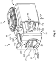
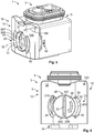
- eine schematische Perspektivansicht der Gehäuseverriegelung in einer Offenstellung und einer Montagestellung;
- Fig. 3
- eine Frontalansicht der Offenstellung und der Montagestellung;
- Fig. 4
- eine Frontalansicht in einer Offenstellung und einer Vorraststellung;
- Fig. 5
- eine schematische Perspektivansicht einer Geschlossenstellung und einer Verriegelungsstellung;
- Fig. 6
- eine Frontalansicht der Geschlossenstellung und der Verriegelungsstellung;
- Fig. 7
- eine schematische Perspektivansicht des Verriegelungselements von vorn;
- Fig. 8
- eine schematische Perspektivansicht des Verriegelungselementes von hinten;
- Fig. 9
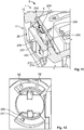
- ein Detail des Schiebers und des Verriegelungselementes in der Vorraststellung;
- Fig. 10
- eine geschnittene, schematische Perspektivansicht des Schiebers, des Verriegelungselementes und des Gehäuses in der Vorraststellung;
- Fig. 11
- eine geschnittene, schematische Perspektivansicht eines Steckers in der Geschlossenstellung und der Verriegelungsstellung;
- Fig. 12
- eine Ansicht eines Verriegelungselementes zusammen mit dem Schieber in der Montagestellung.
- In der
Fig. 1 ist eine Steckverbindung 2 mit einem Stecker 3 und einem lediglich angedeuteten Gegenstecker 4 dargestellt. - Der Stecker 3 umfasst insbesondere ein Gehäuse 5, an dem eine Gehäuseverriegelung 1 angebracht werden kann.
- Die Gehäuseverriegelung 1 umfasst einen Schieber 10 und ein Verriegelungselement 20.
- Der Schieber 10 kann entlang eines Verschiebewegs 100 relativ zu dem Gehäuse 5 verschoben werden und teilweise in dieses eingeschoben werden. Das Verriegelungselement 20 kann durch eine Einsetzöffnung 17 in den Schieber 10 eingesetzt werden und dort entlang eines Bewegungspfads 200 rotiert werden. In der
Fig. 1 ist eine Explosionsdarstellung gezeigt, die auch als eine Vormontageposition angesehen werden kann, in der die Gehäuseverriegelung 1 noch nicht mit dem Rest des Steckers 3 verbunden ist. - Der Stecker 3 kann entlang einer Steckrichtung 34 mit dem Gegenstecker 4 zusammengesteckt werden. Dies ist möglich, wenn der Schieber 10 nicht in einer Geschlossenstellung 12 ist.
- In den
Figuren 2 und3 ist eine Offenstellung 11 des Schiebers 10 dargestellt, in der der Gegenstecker 4 mit dem Stecker 3 zusammengesteckt werden. Ausgehend von derFig. 1 wurde der Schieber 10 teilweise in das Gehäuse 5 eingesteckt. Das Verriegelungselement 20 wurde durch die Einsetzöffnung 17 in den Schieber 10 eingesetzt und befindet sich nun in der Montagestellung 11. Durch eine Rotation des Verriegelungselementes 20 wird dieses in die inFig. 4 gezeigte Vorraststellung 12 gebracht. In der Vorraststellung 12 ist das Verriegelungselement 20 in dem Schieber 10 drehbar gehalten und kann deshalb nicht mehr verloren gehen. Die Rotation erfolgt dabei entlang eines Bewegungspfads 200 des Verriegelungselementes 20. Das Verriegelungselement 20 rotiert dabei um eine Rotationsachse 32, die zentral durch das Verriegelungselement 20 verläuft. Der Schieber 10 kann sich dabei immer noch in der Offenstellung 11 befinden. Alternativ kann er sich auch schon in der Geschlossenstellung 12 befinden. - In der Vorraststellung 22 liegt ein Anschlag 25 des Verriegelungselementes 20 an einem Anschlag 15 des Schiebers an, siehe auch
Fig. 9 . Der Anschlag 25 des Verriegelungselementes 20 ist dabei am Ende 20a eines Armes 29 angeordnet, um eine leichte Auslenkung des Anschlages 25 zu ermöglichen. Wird der Schieber 10 nun in die Geschlossenstellung 12 überführt, indem er entlang des Verschiebewegs 100 bewegt wird, so lenkt eine Entsperrvorrichtung 70 mit einem Vorsprung 71, der sich am Gehäuse 5 befindet, den Arm 29 und den Anschlag 25 in einer Auslenkrichtung 290, die zur Rotationsachse 32 hin gerichtet und senkrecht zu dieser ist, aus und bringt damit den Anschlag 25 mit den Anschlag 15 außer Eingriff. Die Schräge 72 erleichtert dabei die Auslenkung. Dann kann das Verriegelungselement 20 entlang des Bewegungspfads 200 weiter rotiert werden. Formschlusselemente 209 sorgen in der dann erreichten Verriegelungsstellung 23 zusammen mit weiteren Formschlusselementen 210 für eine Verbindung zwischen dem Gehäuse 5 und dem Verriegelungselement 20 bzw. dem Verriegelungselement 20 und dem Schieber 10. - Das Verriegelungselement 20 lässt sich durch eine einfache und durchgängige Rotation von der Montagestellung 21 über die Vorraststellung 22 in die Verriegelungsstellung 23 bringen. Dabei ist ein Überführen in die Verriegelungsstellung 23 jedoch nur möglich, wenn der Schieber 10 in der Geschlossenstellung 12 ist. In dieser Geschlossenstellung 12 hält der Schieber 10 den Gegenstecker 4 am Stecker 3 fest.
- Da der Anschlag 25 an einem zum Gehäuse 5 hin ragenden Vorsprung 28 des Arms 29 angeordnet ist, kann der Arm 29 und insbesondere dessen Ende 29a wieder in seine ursprüngliche Stellung zurückspringen, wenn der Vorsprung 28 nach der Rotation aus der Vorraststellung 22 heraus an dem Vorsprung 71 vorbei rotiert ist. Eine übermäßige Belastung des Arms 29 und ein Brechen sind dadurch verhindert. Der Arm 29 ist insgesamt etwa L-förmig mit einem langen Schenkel und einem kurzen Schenkel, der den Vorsprung 28 umfasst.
- In den
Figuren 5 und 6 ist die Geschlossenstellung 12 gezeigt, in der eine Relativbewegung zwischen dem Stecker 3 und dem Gegenstecker 4 nicht mehr möglich ist. Das Verriegelungselement 20 hält den Schieber 10 dabei in der Geschlossenstellung 12, da es sich in der Verriegelungsstellung 23 befindet, in der es mit dem Gehäuse 5 verriegelt ist. - Das Verriegelungselement 20 ist als Flachkörper 205 ausgebildet. Es ist etwa teller-, platten- oder münzförmig. Es hat eine Basis 220 in Form eines kurzen zylindrischen Stücks und zwei davon abstehende Flügel 230. An der Basis 220 und den Flügeln 230 liegende Flächen und Kanten dienen als Rotationsführungen 30 für die Rotation des Verriegelungselementes 20 im Schieber 10. Ein Anschlag 42, der am Ende eines Kanals 235 in einem Flügel 230 angeordnet ist, dient dazu, ein versehentliches Zurückbewegen in die Montagestellung 11, in der das Verriegelungselement 20 aus dem Schieber 10 herausfallen könnte, zu verhindern. Bei der Überführung von der Montagestellung 21 in die Vorraststellung 22 schnappt ein entsprechendes rampenartiges Gegenelement 241 am Schieber 10 hinter dem Anschlag 240 ein.
- Um das Verriegelungselement 20 in der Vorraststellung 22 und der Verriegelungsstellung 23 leicht lösbar zu halten, verfügt das Verriegelungselement 20 über Rastelemente 60, die mit Einbuchtungen 62 im Schieber 10 zusammenwirken.
- Der Schieber 10 weist eine Andrückführung 120 auf, die den Gegenstecker 4 automatisch an den Stecker 3 zieht, wenn der Schieber 10 in die Geschlossenstellung 12 überführt wird. Die Andrückführung 120 umfasst eine schräg verlaufende Nut 121, die eine Kulisse 122 für ein entsprechendes Gegenelement am Gegenstecker 4 bildet. Führungselemente 110 führen dabei den Schieber 10 relativ zum Stecker 3 senkrecht zur Steckrichtung 34 und damit schräg zur Andrückführung 120.
- Das Verriegelungselement 20 weist ferner einen Krafteinleitungsabschnitt 207 auf, der hier als Leiste ausgebildet ist und dazu dient, die für die Rotation notwendige Kraft in das Verriegelungselement 20 einzuleiten. Der Krafteinleitungsabschnitt 207 hat gleichzeitig eine Doppelfunktion und dient auch noch als Halteelement 208, mit dem das Verriegelungselement 20 bei der Montage gehalten werden kann.
- Rastverbindungen 80 sind z.B. zwischen dem Schieber 10 und dem Gehäuse 5 angebracht und können neben einer Verrastung der beiden auch dazu dienen, dem Benutzer das Erreichen der korrekten Position taktil, akustisch oder optisch etwa durch Klicken anzuzeigen. Solche Rastverbindungen 80 können auch zwischen weiteren Elementen bestehen.
- In einer nicht gezeigten Ausführungsform könnten die beiden Flügel 230 auch gleich ausgebildet sein, um ein Einsetzen in einer beliebigen Rotationsposition zu ermöglichen. Ferner könnten auch die Vorderseite und die Rückseite des Verriegelungselementes 20 symmetrisch zueinander ausgebildet sein, um ein noch leichteres Einsetzen zu ermöglichen. Dazu könnten die Formschlusselemente 209 als Krafteinleitungsabschnitt 207 und als Halteelemente 208 genutzt werden.
-
- 1
- Gehäuseverriegelung
- 2
- Steckverbindung
- 3
- Stecker
- 4
- Gegenstecker
- 5
- Gehäuse
- 10
- Schieber
- 11
- Offenstellung
- 12
- Geschlossenstellung
- 15
- Anschlag Schieber
- 17
- Einsetzöffnung
- 20
- Verriegelungselement
- 21
- Montagestellung
- 22
- Vorraststellung
- 23
- Verriegelungsstellung
- 25
- Anschlag Verriegelungselement
- 28
- Vorsprung Arm
- 29
- Arm
- 29a
- Ende des Arms
- 30
- Rotationsführung
- 31
- Rotationsrichtung
- 32
- Rotationsachse
- 34
- Steckrichtung
- 60
- Rastelement
- 61
- Rastnoppen
- 62
- Einbuchtung
- 70
- Entsperrvorrichtung
- 71
- Vorsprung
- 72
- Schräge
- 80
- Rastverbindungen
- 100
- Verschiebeweg
- 110
- Führungselemente Verschiebeweg
- 120
- Andrückführung
- 121
- Nut
- 122
- Kulisse
- 200
- Bewegungspfad
- 205
- Flachkörper
- 207
- Krafteinleitungsabschnitt
- 208
- Halteelement
- 209
- Formsöhlusselement Gehäuse Verriegelungselement
- 210
- Formschlusselement Schieber Verriegelungselement
- 220
- Basis
- 230
- Flügel
- 235
- Kanal
- 240
- Anschlag
- 241
- Gegenelement
- 290
- Auslenkrichtung Arm
Claims (15)
- Gehäuseverriegelung (1) für eine elektrische Steckverbindung (2) zwischen einem Stecker (3) und einem Gegenstecker (4), umfassend
einen an einem Gehäuse (4) des Steckers (3) anbringbaren Schieber (10), wobei der Schieber (10) entlang eines Verschiebewegs (100) von einer Offenstellung (11), in der der Stecker (3) relativ zu dem Gegenstecker (4) beweglich ist, in eine Geschlossenstellung (12), in der der Stecker (3) gegenüber dem Gegenstecker (4) unbeweglich ist, überführbar ist, und
ein Verriegelungselement (20), das in eine Verriegelungsstellung (23) bewegbar ist, in der das Verriegelungselement (20) den Schieber (10) in der Geschlossenstellung (12) hält, wobei das Verriegelungselement (20) nur in die Verriegelungsstellung (23) bewegt werden kann, wenn der Schieber (10) in der Geschlossenstellung (12) ist,
wobei das Verriegelungselement (20) durch eine Rotation in die Verriegelungsstellung (23) bewegbar ist. - Gehäuseverriegelung (1) nach Anspruch 1, wobei das Verriegelungselement (20) in einer Montagestellung (21) von dem Schieber (10) lösbar und/oder mit diesem verbindbar ist.
- Gehäuseverriegelung (1) nach einem der Ansprüche 1 oder 2, wobei in einer Vorraststellung (2) ein Anschlag (25) des Verriegelungselementes (20) an einem Anschlag (15) des Schiebers (10) anliegt, wenn der Schieber (10) außerhalb der Geschlossenstellung (12) ist.
- Gehäuseverriegelung (1) nach einem der Ansprüche 1 bis 3, wobei in der Vorraststellung (22) das Verriegelungselement (20) in dem Schieber (10) gehalten ist.
- Gehäuseverriegelung (1) nach einem der Ansprüche 1 bis 4, wobei die Vorraststellung (22) auf einem Bewegungspfad (200) zwischen der Montagestellung (21) und der Verriegelungsstellung (23) liegt.
- Gehäuseverriegelung (1) nach einem der Ansprüche 1 bis 5, wobei das Verriegelungselement (20) durch eine Rotation von der Montagestellung (21) in die Vorraststellung (22) und/oder von der Vorraststellung (22) in die Verriegelungsstellung (23) überführbar ist.
- Gehäuseverriegelung (1) nach einem der Ansprüche 3 bis 6, wobei der Anschlag (25) des Verriegelungselements (20) und/oder der Anschlag (15) des Schiebers (10) an einem auslenkbaren Arm (29) angeordnet sind.
- Gehäuseverriegelung (1) nach einem der Ansprüche 1 bis 7, wobei eine Rotationsachse (32) der Rotation in die Verriegelungsstellung (23) durch das Verriegelungselement (20) verläuft.
- Gehäuseverriegelung (1) nach einem der Ansprüche 1 bis 8, wobei der Schieber (10) und/oder das Verriegelungselement (20) Rastelemente (61, 62) aufweisen, mittels denen das Verriegelungselement (20) in der Montagestellung (21), der Vorraststellung (22) und/oder der Verriegelungsstellung (23) verrastet ist.
- Gehäuseverriegelung (1) nach einem der Ansprüche 1 bis 9, wobei der Schieber (10) eine Andrückführung (120) aufweist, die den Gegenstecker (4) automatisch an den Stecker (3) andrückt, wenn der Schieber (10) in die Geschlossenstellung (12) überführt wird.
- Gehäuseverriegelung (1) nach einem der Ansprüche 1 bis 10, wobei das Verriegelungselement (20) als ein Flachkörper (205) ausgebildet ist.
- Gehäuseverriegelung (1) nach einem der Ansprüche 1 bis 11, wobei in der Verriegelungsstellung (23) mit Formschlusselementen (209, 210) eine Verbindung zwischen dem Gehäuse (5) und dem Schieber (10) über das Verriegelungselement (20) hergestellt ist.
- Stecker (3) mit einem Gehäuse (5) und einer Gehäuseverriegelung (1) nach einem der Ansprüche 1 bis 12, wobei der Stecker eine Entsperrvorrichtung (70) aufweist, die den Anschlag (15) des Schiebers (10) und den Anschlag (25) des Verriegelungselements (20) voneinander löst, wenn der Schieber (10) in der Geschlossenstellung (12) ist.
- Stecker (3) nach Anspruch 13, wobei der Anschlag (25) des Verriegelungselements (20) in der Vorraststellung (22) und in der Verriegelungsstellung (23) des Verriegelungselements (20) in der Geschlossenstellung (12) des Schiebers (10) außer Eingriff mit einem Anschlag (15) des Schiebers (10) ist.
- Steckverbindung (2), umfassend einen Stecker (3) nach Anspruch 13 oder 14 und einen Gegenstecker (4):
Priority Applications (1)
| Application Number | Priority Date | Filing Date | Title |
|---|---|---|---|
| EP16386023.2A EP3340393B1 (de) | 2016-12-22 | 2016-12-22 | Gehäuseverriegelung für eine elektrische steckverbindung zwischen einem stecker und einem gegenstecker, stecker und steckverbindung |
Applications Claiming Priority (1)
| Application Number | Priority Date | Filing Date | Title |
|---|---|---|---|
| EP16386023.2A EP3340393B1 (de) | 2016-12-22 | 2016-12-22 | Gehäuseverriegelung für eine elektrische steckverbindung zwischen einem stecker und einem gegenstecker, stecker und steckverbindung |
Publications (2)
| Publication Number | Publication Date |
|---|---|
| EP3340393A1 true EP3340393A1 (de) | 2018-06-27 |
| EP3340393B1 EP3340393B1 (de) | 2021-03-10 |
Family
ID=57850870
Family Applications (1)
| Application Number | Title | Priority Date | Filing Date |
|---|---|---|---|
| EP16386023.2A Not-in-force EP3340393B1 (de) | 2016-12-22 | 2016-12-22 | Gehäuseverriegelung für eine elektrische steckverbindung zwischen einem stecker und einem gegenstecker, stecker und steckverbindung |
Country Status (1)
| Country | Link |
|---|---|
| EP (1) | EP3340393B1 (de) |
Citations (3)
| Publication number | Priority date | Publication date | Assignee | Title |
|---|---|---|---|---|
| WO2004015820A1 (en) * | 2002-08-06 | 2004-02-19 | Fci | Electric connector |
| WO2010015888A1 (en) * | 2008-08-04 | 2010-02-11 | Fci | Electrical connector assembly, an electrical device comprising the same and a method for unmating the same |
| US9293860B1 (en) * | 2014-09-22 | 2016-03-22 | Hyundai Motor Company | Connector for a vehicle |
-
2016
- 2016-12-22 EP EP16386023.2A patent/EP3340393B1/de not_active Not-in-force
Patent Citations (3)
| Publication number | Priority date | Publication date | Assignee | Title |
|---|---|---|---|---|
| WO2004015820A1 (en) * | 2002-08-06 | 2004-02-19 | Fci | Electric connector |
| WO2010015888A1 (en) * | 2008-08-04 | 2010-02-11 | Fci | Electrical connector assembly, an electrical device comprising the same and a method for unmating the same |
| US9293860B1 (en) * | 2014-09-22 | 2016-03-22 | Hyundai Motor Company | Connector for a vehicle |
Also Published As
| Publication number | Publication date |
|---|---|
| EP3340393B1 (de) | 2021-03-10 |
Similar Documents
| Publication | Publication Date | Title |
|---|---|---|
| DE102013015719B4 (de) | Hebeltypverbinder mit Ritzelzähnen und Verfahren zum Zusammenbauen desselben | |
| DE102016121291B4 (de) | Verbinderanordnung vom Typ mit Hebel | |
| DE102004063236B4 (de) | Verbinder, welcher ein bewegbares Glied aufweist, und Verbinderanordnung | |
| DE102012111408B3 (de) | Verriegelungsmechanismus für Steckverbinder | |
| EP3176885B1 (de) | Steckerverbinderanordnung | |
| DE102018129450A1 (de) | Türgarnitur mit einer einseitig verriegelbaren Handhabe | |
| DE202013011923U1 (de) | Prüfsteckerblock | |
| DE102008053137A1 (de) | Hebelverbindung | |
| DE1665644C3 (de) | Elektrische Steckvorrichtung | |
| DE102005048410B4 (de) | Verbinder und Verbinderanordnung | |
| DE102021102477A1 (de) | Leiteranschlussklemme | |
| DE102018202891B4 (de) | Hebelverbinder | |
| DE102022118993A1 (de) | Gehäuseanordnung für einen elektrischen Stecker mit einer Steckhilfe sowie elektrischer Stecker und Steckeranordnung | |
| EP3403298B1 (de) | Steckverbinder | |
| DE102020126486A1 (de) | Halterahmen für einen Steckverbinder | |
| EP3340393B1 (de) | Gehäuseverriegelung für eine elektrische steckverbindung zwischen einem stecker und einem gegenstecker, stecker und steckverbindung | |
| DE102020116391A1 (de) | Elektrischer anschluss mit verbindungsassistenz undrückkopplung | |
| DE202011000739U1 (de) | Steckverbindungsanordnung für elektrische Leiter | |
| EP1679767B1 (de) | Elektrischer Steckverbinder | |
| BE1029587B1 (de) | Steckverbinder mit wählbarer Entriegelung | |
| DE102004018152A1 (de) | Steckverbinder mit Verzahnung und Fehlsteckanschlag | |
| DE3620105C1 (en) | Electrical contact switch | |
| DE102021118012A1 (de) | Steckverbinder mit wählbarer Entriegelung | |
| EP2513395B1 (de) | Arretiervorrichtung zur arretierung eines schlüssels an einem schliesszylinder | |
| DE10346367B4 (de) | Freidrehbarer HF-Winkelsteckverbinder |
Legal Events
| Date | Code | Title | Description |
|---|---|---|---|
| PUAI | Public reference made under article 153(3) epc to a published international application that has entered the european phase |
Free format text: ORIGINAL CODE: 0009012 |
|
| STAA | Information on the status of an ep patent application or granted ep patent |
Free format text: STATUS: THE APPLICATION HAS BEEN PUBLISHED |
|
| AK | Designated contracting states |
Kind code of ref document: A1 Designated state(s): AL AT BE BG CH CY CZ DE DK EE ES FI FR GB GR HR HU IE IS IT LI LT LU LV MC MK MT NL NO PL PT RO RS SE SI SK SM TR |
|
| AX | Request for extension of the european patent |
Extension state: BA ME |
|
| STAA | Information on the status of an ep patent application or granted ep patent |
Free format text: STATUS: REQUEST FOR EXAMINATION WAS MADE |
|
| 17P | Request for examination filed |
Effective date: 20181105 |
|
| RBV | Designated contracting states (corrected) |
Designated state(s): AL AT BE BG CH CY CZ DE DK EE ES FI FR GB GR HR HU IE IS IT LI LT LU LV MC MK MT NL NO PL PT RO RS SE SI SK SM TR |
|
| STAA | Information on the status of an ep patent application or granted ep patent |
Free format text: STATUS: EXAMINATION IS IN PROGRESS |
|
| 17Q | First examination report despatched |
Effective date: 20200401 |
|
| GRAP | Despatch of communication of intention to grant a patent |
Free format text: ORIGINAL CODE: EPIDOSNIGR1 |
|
| STAA | Information on the status of an ep patent application or granted ep patent |
Free format text: STATUS: GRANT OF PATENT IS INTENDED |
|
| INTG | Intention to grant announced |
Effective date: 20201026 |
|
| GRAS | Grant fee paid |
Free format text: ORIGINAL CODE: EPIDOSNIGR3 |
|
| GRAA | (expected) grant |
Free format text: ORIGINAL CODE: 0009210 |
|
| STAA | Information on the status of an ep patent application or granted ep patent |
Free format text: STATUS: THE PATENT HAS BEEN GRANTED |
|
| AK | Designated contracting states |
Kind code of ref document: B1 Designated state(s): AL AT BE BG CH CY CZ DE DK EE ES FI FR GB GR HR HU IE IS IT LI LT LU LV MC MK MT NL NO PL PT RO RS SE SI SK SM TR |
|
| REG | Reference to a national code |
Ref country code: GB Ref legal event code: FG4D Free format text: NOT ENGLISH |
|
| REG | Reference to a national code |
Ref country code: AT Ref legal event code: REF Ref document number: 1370852 Country of ref document: AT Kind code of ref document: T Effective date: 20210315 Ref country code: CH Ref legal event code: EP |
|
| REG | Reference to a national code |
Ref country code: DE Ref legal event code: R096 Ref document number: 502016012547 Country of ref document: DE |
|
| REG | Reference to a national code |
Ref country code: IE Ref legal event code: FG4D Free format text: LANGUAGE OF EP DOCUMENT: GERMAN |
|
| REG | Reference to a national code |
Ref country code: LT Ref legal event code: MG9D |
|
| PG25 | Lapsed in a contracting state [announced via postgrant information from national office to epo] |
Ref country code: NO Free format text: LAPSE BECAUSE OF FAILURE TO SUBMIT A TRANSLATION OF THE DESCRIPTION OR TO PAY THE FEE WITHIN THE PRESCRIBED TIME-LIMIT Effective date: 20210610 Ref country code: HR Free format text: LAPSE BECAUSE OF FAILURE TO SUBMIT A TRANSLATION OF THE DESCRIPTION OR TO PAY THE FEE WITHIN THE PRESCRIBED TIME-LIMIT Effective date: 20210310 Ref country code: GR Free format text: LAPSE BECAUSE OF FAILURE TO SUBMIT A TRANSLATION OF THE DESCRIPTION OR TO PAY THE FEE WITHIN THE PRESCRIBED TIME-LIMIT Effective date: 20210611 Ref country code: FI Free format text: LAPSE BECAUSE OF FAILURE TO SUBMIT A TRANSLATION OF THE DESCRIPTION OR TO PAY THE FEE WITHIN THE PRESCRIBED TIME-LIMIT Effective date: 20210310 Ref country code: BG Free format text: LAPSE BECAUSE OF FAILURE TO SUBMIT A TRANSLATION OF THE DESCRIPTION OR TO PAY THE FEE WITHIN THE PRESCRIBED TIME-LIMIT Effective date: 20210610 Ref country code: LT Free format text: LAPSE BECAUSE OF FAILURE TO SUBMIT A TRANSLATION OF THE DESCRIPTION OR TO PAY THE FEE WITHIN THE PRESCRIBED TIME-LIMIT Effective date: 20210310 |
|
| REG | Reference to a national code |
Ref country code: NL Ref legal event code: MP Effective date: 20210310 |
|
| PG25 | Lapsed in a contracting state [announced via postgrant information from national office to epo] |
Ref country code: SE Free format text: LAPSE BECAUSE OF FAILURE TO SUBMIT A TRANSLATION OF THE DESCRIPTION OR TO PAY THE FEE WITHIN THE PRESCRIBED TIME-LIMIT Effective date: 20210310 Ref country code: LV Free format text: LAPSE BECAUSE OF FAILURE TO SUBMIT A TRANSLATION OF THE DESCRIPTION OR TO PAY THE FEE WITHIN THE PRESCRIBED TIME-LIMIT Effective date: 20210310 Ref country code: RS Free format text: LAPSE BECAUSE OF FAILURE TO SUBMIT A TRANSLATION OF THE DESCRIPTION OR TO PAY THE FEE WITHIN THE PRESCRIBED TIME-LIMIT Effective date: 20210310 |
|
| PG25 | Lapsed in a contracting state [announced via postgrant information from national office to epo] |
Ref country code: NL Free format text: LAPSE BECAUSE OF FAILURE TO SUBMIT A TRANSLATION OF THE DESCRIPTION OR TO PAY THE FEE WITHIN THE PRESCRIBED TIME-LIMIT Effective date: 20210310 |
|
| PG25 | Lapsed in a contracting state [announced via postgrant information from national office to epo] |
Ref country code: SM Free format text: LAPSE BECAUSE OF FAILURE TO SUBMIT A TRANSLATION OF THE DESCRIPTION OR TO PAY THE FEE WITHIN THE PRESCRIBED TIME-LIMIT Effective date: 20210310 Ref country code: EE Free format text: LAPSE BECAUSE OF FAILURE TO SUBMIT A TRANSLATION OF THE DESCRIPTION OR TO PAY THE FEE WITHIN THE PRESCRIBED TIME-LIMIT Effective date: 20210310 Ref country code: CZ Free format text: LAPSE BECAUSE OF FAILURE TO SUBMIT A TRANSLATION OF THE DESCRIPTION OR TO PAY THE FEE WITHIN THE PRESCRIBED TIME-LIMIT Effective date: 20210310 |
|
| PG25 | Lapsed in a contracting state [announced via postgrant information from national office to epo] |
Ref country code: IS Free format text: LAPSE BECAUSE OF FAILURE TO SUBMIT A TRANSLATION OF THE DESCRIPTION OR TO PAY THE FEE WITHIN THE PRESCRIBED TIME-LIMIT Effective date: 20210710 Ref country code: SK Free format text: LAPSE BECAUSE OF FAILURE TO SUBMIT A TRANSLATION OF THE DESCRIPTION OR TO PAY THE FEE WITHIN THE PRESCRIBED TIME-LIMIT Effective date: 20210310 Ref country code: RO Free format text: LAPSE BECAUSE OF FAILURE TO SUBMIT A TRANSLATION OF THE DESCRIPTION OR TO PAY THE FEE WITHIN THE PRESCRIBED TIME-LIMIT Effective date: 20210310 Ref country code: PT Free format text: LAPSE BECAUSE OF FAILURE TO SUBMIT A TRANSLATION OF THE DESCRIPTION OR TO PAY THE FEE WITHIN THE PRESCRIBED TIME-LIMIT Effective date: 20210712 Ref country code: PL Free format text: LAPSE BECAUSE OF FAILURE TO SUBMIT A TRANSLATION OF THE DESCRIPTION OR TO PAY THE FEE WITHIN THE PRESCRIBED TIME-LIMIT Effective date: 20210310 |
|
| REG | Reference to a national code |
Ref country code: DE Ref legal event code: R097 Ref document number: 502016012547 Country of ref document: DE |
|
| PLBE | No opposition filed within time limit |
Free format text: ORIGINAL CODE: 0009261 |
|
| STAA | Information on the status of an ep patent application or granted ep patent |
Free format text: STATUS: NO OPPOSITION FILED WITHIN TIME LIMIT |
|
| PG25 | Lapsed in a contracting state [announced via postgrant information from national office to epo] |
Ref country code: DK Free format text: LAPSE BECAUSE OF FAILURE TO SUBMIT A TRANSLATION OF THE DESCRIPTION OR TO PAY THE FEE WITHIN THE PRESCRIBED TIME-LIMIT Effective date: 20210310 Ref country code: ES Free format text: LAPSE BECAUSE OF FAILURE TO SUBMIT A TRANSLATION OF THE DESCRIPTION OR TO PAY THE FEE WITHIN THE PRESCRIBED TIME-LIMIT Effective date: 20210310 Ref country code: AL Free format text: LAPSE BECAUSE OF FAILURE TO SUBMIT A TRANSLATION OF THE DESCRIPTION OR TO PAY THE FEE WITHIN THE PRESCRIBED TIME-LIMIT Effective date: 20210310 |
|
| PGFP | Annual fee paid to national office [announced via postgrant information from national office to epo] |
Ref country code: DE Payment date: 20211027 Year of fee payment: 6 |
|
| 26N | No opposition filed |
Effective date: 20211213 |
|
| PG25 | Lapsed in a contracting state [announced via postgrant information from national office to epo] |
Ref country code: SI Free format text: LAPSE BECAUSE OF FAILURE TO SUBMIT A TRANSLATION OF THE DESCRIPTION OR TO PAY THE FEE WITHIN THE PRESCRIBED TIME-LIMIT Effective date: 20210310 |
|
| PG25 | Lapsed in a contracting state [announced via postgrant information from national office to epo] |
Ref country code: IT Free format text: LAPSE BECAUSE OF FAILURE TO SUBMIT A TRANSLATION OF THE DESCRIPTION OR TO PAY THE FEE WITHIN THE PRESCRIBED TIME-LIMIT Effective date: 20210310 |
|
| PG25 | Lapsed in a contracting state [announced via postgrant information from national office to epo] |
Ref country code: IS Free format text: LAPSE BECAUSE OF FAILURE TO SUBMIT A TRANSLATION OF THE DESCRIPTION OR TO PAY THE FEE WITHIN THE PRESCRIBED TIME-LIMIT Effective date: 20210710 |
|
| PG25 | Lapsed in a contracting state [announced via postgrant information from national office to epo] |
Ref country code: MC Free format text: LAPSE BECAUSE OF FAILURE TO SUBMIT A TRANSLATION OF THE DESCRIPTION OR TO PAY THE FEE WITHIN THE PRESCRIBED TIME-LIMIT Effective date: 20210310 |
|
| REG | Reference to a national code |
Ref country code: CH Ref legal event code: PL |
|
| GBPC | Gb: european patent ceased through non-payment of renewal fee |
Effective date: 20211222 |
|
| REG | Reference to a national code |
Ref country code: BE Ref legal event code: MM Effective date: 20211231 |
|
| PG25 | Lapsed in a contracting state [announced via postgrant information from national office to epo] |
Ref country code: LU Free format text: LAPSE BECAUSE OF NON-PAYMENT OF DUE FEES Effective date: 20211222 Ref country code: IE Free format text: LAPSE BECAUSE OF NON-PAYMENT OF DUE FEES Effective date: 20211222 Ref country code: GB Free format text: LAPSE BECAUSE OF NON-PAYMENT OF DUE FEES Effective date: 20211222 |
|
| PG25 | Lapsed in a contracting state [announced via postgrant information from national office to epo] |
Ref country code: FR Free format text: LAPSE BECAUSE OF NON-PAYMENT OF DUE FEES Effective date: 20211231 Ref country code: BE Free format text: LAPSE BECAUSE OF NON-PAYMENT OF DUE FEES Effective date: 20211231 |
|
| PG25 | Lapsed in a contracting state [announced via postgrant information from national office to epo] |
Ref country code: LI Free format text: LAPSE BECAUSE OF NON-PAYMENT OF DUE FEES Effective date: 20211231 Ref country code: CH Free format text: LAPSE BECAUSE OF NON-PAYMENT OF DUE FEES Effective date: 20211231 |
|
| REG | Reference to a national code |
Ref country code: AT Ref legal event code: MM01 Ref document number: 1370852 Country of ref document: AT Kind code of ref document: T Effective date: 20211222 |
|
| PG25 | Lapsed in a contracting state [announced via postgrant information from national office to epo] |
Ref country code: AT Free format text: LAPSE BECAUSE OF NON-PAYMENT OF DUE FEES Effective date: 20211222 |
|
| PG25 | Lapsed in a contracting state [announced via postgrant information from national office to epo] |
Ref country code: HU Free format text: LAPSE BECAUSE OF FAILURE TO SUBMIT A TRANSLATION OF THE DESCRIPTION OR TO PAY THE FEE WITHIN THE PRESCRIBED TIME-LIMIT; INVALID AB INITIO Effective date: 20161222 |
|
| PG25 | Lapsed in a contracting state [announced via postgrant information from national office to epo] |
Ref country code: CY Free format text: LAPSE BECAUSE OF FAILURE TO SUBMIT A TRANSLATION OF THE DESCRIPTION OR TO PAY THE FEE WITHIN THE PRESCRIBED TIME-LIMIT Effective date: 20210310 |
|
| REG | Reference to a national code |
Ref country code: DE Ref legal event code: R119 Ref document number: 502016012547 Country of ref document: DE |
|
| PG25 | Lapsed in a contracting state [announced via postgrant information from national office to epo] |
Ref country code: DE Free format text: LAPSE BECAUSE OF NON-PAYMENT OF DUE FEES Effective date: 20230701 |
|
| PG25 | Lapsed in a contracting state [announced via postgrant information from national office to epo] |
Ref country code: MK Free format text: LAPSE BECAUSE OF FAILURE TO SUBMIT A TRANSLATION OF THE DESCRIPTION OR TO PAY THE FEE WITHIN THE PRESCRIBED TIME-LIMIT Effective date: 20210310 |
|
| PG25 | Lapsed in a contracting state [announced via postgrant information from national office to epo] |
Ref country code: MT Free format text: LAPSE BECAUSE OF FAILURE TO SUBMIT A TRANSLATION OF THE DESCRIPTION OR TO PAY THE FEE WITHIN THE PRESCRIBED TIME-LIMIT Effective date: 20210310 |
|
| PG25 | Lapsed in a contracting state [announced via postgrant information from national office to epo] |
Ref country code: TR Free format text: LAPSE BECAUSE OF FAILURE TO SUBMIT A TRANSLATION OF THE DESCRIPTION OR TO PAY THE FEE WITHIN THE PRESCRIBED TIME-LIMIT Effective date: 20210310 |