EP3339134B1 - Hohlprofileinsteckstopfen - Google Patents
Hohlprofileinsteckstopfen Download PDFInfo
- Publication number
- EP3339134B1 EP3339134B1 EP17205055.1A EP17205055A EP3339134B1 EP 3339134 B1 EP3339134 B1 EP 3339134B1 EP 17205055 A EP17205055 A EP 17205055A EP 3339134 B1 EP3339134 B1 EP 3339134B1
- Authority
- EP
- European Patent Office
- Prior art keywords
- hollow profile
- hollow
- insertion plug
- plug
- base body
- Prior art date
- Legal status (The legal status is an assumption and is not a legal conclusion. Google has not performed a legal analysis and makes no representation as to the accuracy of the status listed.)
- Active
Links
Images


Classifications
-
- B—PERFORMING OPERATIONS; TRANSPORTING
- B62—LAND VEHICLES FOR TRAVELLING OTHERWISE THAN ON RAILS
- B62B—HAND-PROPELLED VEHICLES, e.g. HAND CARTS OR PERAMBULATORS; SLEDGES
- B62B5/00—Accessories or details specially adapted for hand carts
- B62B5/0006—Bumpers; Safety devices
-
- A—HUMAN NECESSITIES
- A61—MEDICAL OR VETERINARY SCIENCE; HYGIENE
- A61B—DIAGNOSIS; SURGERY; IDENTIFICATION
- A61B17/00—Surgical instruments, devices or methods
- A61B17/56—Surgical instruments or methods for treatment of bones or joints; Devices specially adapted therefor
- A61B17/58—Surgical instruments or methods for treatment of bones or joints; Devices specially adapted therefor for osteosynthesis, e.g. bone plates, screws or setting implements
- A61B17/88—Osteosynthesis instruments; Methods or means for implanting or extracting internal or external fixation devices
- A61B17/8875—Screwdrivers, spanners or wrenches
-
- B—PERFORMING OPERATIONS; TRANSPORTING
- B25—HAND TOOLS; PORTABLE POWER-DRIVEN TOOLS; MANIPULATORS
- B25B—TOOLS OR BENCH DEVICES NOT OTHERWISE PROVIDED FOR, FOR FASTENING, CONNECTING, DISENGAGING, OR HOLDING
- B25B23/00—Details of, or accessories for, spanners, wrenches, screwdrivers
- B25B23/14—Arrangement of torque limiters or torque indicators in wrenches or screwdrivers
- B25B23/141—Mechanical overload release couplings
-
- B—PERFORMING OPERATIONS; TRANSPORTING
- B65—CONVEYING; PACKING; STORING; HANDLING THIN OR FILAMENTARY MATERIAL
- B65D—CONTAINERS FOR STORAGE OR TRANSPORT OF ARTICLES OR MATERIALS, e.g. BAGS, BARRELS, BOTTLES, BOXES, CANS, CARTONS, CRATES, DRUMS, JARS, TANKS, HOPPERS, FORWARDING CONTAINERS; ACCESSORIES, CLOSURES, OR FITTINGS THEREFOR; PACKAGING ELEMENTS; PACKAGES
- B65D59/00—Plugs, sleeves, caps, or like rigid or semi-rigid elements for protecting parts of articles or for bundling articles, e.g. protectors for screw-threads, end caps for tubes or for bundling rod-shaped articles
- B65D59/02—Plugs
-
- F—MECHANICAL ENGINEERING; LIGHTING; HEATING; WEAPONS; BLASTING
- F16—ENGINEERING ELEMENTS AND UNITS; GENERAL MEASURES FOR PRODUCING AND MAINTAINING EFFECTIVE FUNCTIONING OF MACHINES OR INSTALLATIONS; THERMAL INSULATION IN GENERAL
- F16B—DEVICES FOR FASTENING OR SECURING CONSTRUCTIONAL ELEMENTS OR MACHINE PARTS TOGETHER, e.g. NAILS, BOLTS, CIRCLIPS, CLAMPS, CLIPS OR WEDGES; JOINTS OR JOINTING
- F16B2/00—Friction-grip releasable fastenings
- F16B2/20—Clips, i.e. with gripping action effected solely by the inherent resistance to deformation of the material of the fastening
- F16B2/22—Clips, i.e. with gripping action effected solely by the inherent resistance to deformation of the material of the fastening of resilient material, e.g. rubbery material
-
- A—HUMAN NECESSITIES
- A61—MEDICAL OR VETERINARY SCIENCE; HYGIENE
- A61B—DIAGNOSIS; SURGERY; IDENTIFICATION
- A61B17/00—Surgical instruments, devices or methods
- A61B2017/0023—Surgical instruments, devices or methods disposable
-
- A—HUMAN NECESSITIES
- A61—MEDICAL OR VETERINARY SCIENCE; HYGIENE
- A61B—DIAGNOSIS; SURGERY; IDENTIFICATION
- A61B17/00—Surgical instruments, devices or methods
- A61B2017/00367—Details of actuation of instruments, e.g. relations between pushing buttons, or the like, and activation of the tool, working tip, or the like
- A61B2017/00398—Details of actuation of instruments, e.g. relations between pushing buttons, or the like, and activation of the tool, working tip, or the like using powered actuators, e.g. stepper motors, solenoids
-
- A—HUMAN NECESSITIES
- A61—MEDICAL OR VETERINARY SCIENCE; HYGIENE
- A61B—DIAGNOSIS; SURGERY; IDENTIFICATION
- A61B90/00—Instruments, implements or accessories specially adapted for surgery or diagnosis and not covered by any of the groups A61B1/00 - A61B50/00, e.g. for luxation treatment or for protecting wound edges
- A61B90/03—Automatic limiting or abutting means, e.g. for safety
- A61B2090/031—Automatic limiting or abutting means, e.g. for safety torque limiting
-
- F—MECHANICAL ENGINEERING; LIGHTING; HEATING; WEAPONS; BLASTING
- F16—ENGINEERING ELEMENTS AND UNITS; GENERAL MEASURES FOR PRODUCING AND MAINTAINING EFFECTIVE FUNCTIONING OF MACHINES OR INSTALLATIONS; THERMAL INSULATION IN GENERAL
- F16B—DEVICES FOR FASTENING OR SECURING CONSTRUCTIONAL ELEMENTS OR MACHINE PARTS TOGETHER, e.g. NAILS, BOLTS, CIRCLIPS, CLAMPS, CLIPS OR WEDGES; JOINTS OR JOINTING
- F16B21/00—Means for preventing relative axial movement of a pin, spigot, shaft or the like and a member surrounding it; Stud-and-socket releasable fastenings
- F16B21/06—Releasable fastening devices with snap-action
- F16B21/08—Releasable fastening devices with snap-action in which the stud, pin, or spigot has a resilient part
- F16B21/086—Releasable fastening devices with snap-action in which the stud, pin, or spigot has a resilient part the shank of the stud, pin or spigot having elevations, ribs, fins or prongs intended for deformation or tilting predominantly in a direction perpendicular to the direction of insertion
-
- F—MECHANICAL ENGINEERING; LIGHTING; HEATING; WEAPONS; BLASTING
- F16—ENGINEERING ELEMENTS AND UNITS; GENERAL MEASURES FOR PRODUCING AND MAINTAINING EFFECTIVE FUNCTIONING OF MACHINES OR INSTALLATIONS; THERMAL INSULATION IN GENERAL
- F16B—DEVICES FOR FASTENING OR SECURING CONSTRUCTIONAL ELEMENTS OR MACHINE PARTS TOGETHER, e.g. NAILS, BOLTS, CIRCLIPS, CLAMPS, CLIPS OR WEDGES; JOINTS OR JOINTING
- F16B7/00—Connections of rods or tubes, e.g. of non-circular section, mutually, including resilient connections
- F16B7/04—Clamping or clipping connections
- F16B7/0406—Clamping or clipping connections for rods or tubes being coaxial
- F16B7/0413—Clamping or clipping connections for rods or tubes being coaxial for tubes using the innerside thereof
- F16B7/042—Clamping or clipping connections for rods or tubes being coaxial for tubes using the innerside thereof with a locking element, e.g. pin, ball or pushbutton, engaging in a hole in the wall of at least one tube
Definitions
- the present invention relates to a hollow profile plug with a base body for use in an open end of a hollow profile and with a cover side to cover the open end of the hollow profile.
- Hollow profile plug-in plugs of this type are known, for example, in connection with chassis or mobile racks.
- the chassis are usually formed from several hollow profiles, which are screwed or welded together, for example.
- the open ends of the hollow profiles are then closed with hollow profile insertion plugs.
- the profile end caps or hollow profile insertion plugs are also used as impact protection for stackable or pushable trolleys or chassis.
- corresponding hollow profile insertion plugs are already known from the European Community designs EU-GGM 002325613-0003, 003421403-0001, 003421403-0002, 003424043-0001 and 003424043-0002.
- a hollow profile plug with a base body known. This is used in an open end of a hollow profile and with a cover side to cover the open end of the hollow profile, the cover side being molded onto the base body and having a circumferential protrusion. A depression is provided adjacent to the protrusion in the transition to the adjacent outer surface of the base body.
- German patent application 10 2007 055 868 A1 discloses such a hollow profile plug, which is provided with a cover side, a circumferential projection and a depression.
- a hollow profile plug with the features of claim 1. It is provided that a hollow profile plug with a base body for use in an open end of a hollow profile and with a cover side to cover the open end of the hollow profile is provided, the cover side is integrally formed on the base body and has a circumferential protrusion, a depression being provided adjacent to the protrusion in the transition to the adjacent outer surface of the base body, a rod receptacle being formed in the base body, and the rod receptacle being let into the base body in the form of a tube.
- the invention is based on the basic idea that no essentially rectangular edge is provided between the transition from the cover side to the base body, but that a depression is provided at this point. Through these depressions it is avoided that burrs or the like can arise between the circumferential projection and in the transition to the adjacent outer surface of the base body and these have to be removed accordingly. Due to the depression, a certain flexibility is already assigned to the hollow profile plug, due to the shape, which manifests itself in particular in a certain mobility between the cover side and the base body.
- the cover side itself serves to cover the open end of the hollow profile. When the hollow profile plug is inserted, the cover side is the side of the hollow profile plug in the hollow profile that is visible from the outside.
- the protrusion itself extends beyond the outer surfaces of the base body, which can be seen particularly well in the side view. This protrusion serves to lie on the edges of the hollow profile and to cover or cover them accordingly.
- the depression is circumferential.
- a circumferential depression ensures that the shape-related flexibility is uniform around the cover side and that a corresponding flexibility can be provided on all sides if necessary.
- the hollow profile plug is formed in one piece. In this way, simple manufacture is achieved.
- the hollow profile plug is designed as an injection molded part. In this way, simple and inexpensive, but at the same time high-quality production can be achieved.
- the depressions can also be used in particular to prevent production burrs.
- demolding from an injection mold is also unproblematic.
- the hollow profile plug can be at least partially made of plastic.
- it can be a plastic injection molded part.
- the plastic is an elastic and / or flexible plastic.
- silicone-based plastics, polytetrafluoroethylene (PTFE) and polyvinylidene fluoride (PVDF) plastics are conceivable.
- PTFE polytetrafluoroethylene
- PVDF polyvinylidene fluoride
- PVC polyvinyl chloride
- polyamides polyamides.
- a locking knob can be arranged on at least one outer surface of the base body. By means of the locking knob, it can be achieved that the hollow profile plug can be locked when inserted into the hollow profile. It is conceivable that several latching knobs are also provided on the outer surfaces of the base body.
- a rod holder is formed in the base body.
- the rod receptacles can be used, for example, to attach structures, rods for push handles or the like in the hollow profile.
- Such a construction makes it possible, for example, to insert a rod through corresponding openings in the hollow profile, also through the hollow profile plug or partially through the hollow profile plug, and thus to fasten these three elements to one another or to one another.
- the rod holder can be designed like a clamp.
- the clip can be provided, for example, by two clip fingers that are flexible.
- a clip finger can, for example, rest against the inner wall of the hollow profile, while the second clip finger is arranged to move freely in the hollow profile.
- the rod receptacle is embedded in the basic body in a tubular shape. In this case, a rod is inserted through the base body itself into the rod holder and through the rod holder.
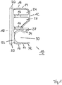
- Fig. 1 shows a perspective view of a hollow profile plug 10.
- the hollow profile plug 10 is integrally formed.
- the hollow profile plug 10 is made of plastic and is designed as a plastic injection molded part.
- the plastic is an elastic and flexible plastic, here polyamide.
- plastics such as polytetrafluoroethylene (PTFE), polyvinylidene fluoride (PVDF), polyvinyl chloride (PVC) or other suitable plastics, for example based on silicone.
- PTFE polytetrafluoroethylene
- PVDF polyvinylidene fluoride
- PVC polyvinyl chloride
- the hollow profile plug 10 has a base body 12 with outer surfaces 14.
- a latching knob 16 is formed in the outer surfaces 14 at several locations. By means of these locking knobs 16, locking in the interior of the hollow profile is achieved.
- the hollow profile plug 10 further has a cover side 18, the cover side being integrally formed on the base body 12.
- cover side 18 has a circumferential protrusion 20 which stands out clearly from the base body 12 and protrudes beyond it.
- a depression 22 is provided in the transition to the adjacent outer surface 14 of the base body 12.
- the depression 22 is circumferential in the embodiment shown.
- a plurality of recesses 24, 26 and 28 are provided in the base body 12.
- the basic body is essentially formed in its interior by walls or webs which are flexible with respect to one another due to the shape.
- the base body 12 is designed to be flexible overall.
- the base body 12 also has a rod holder 30, likewise formed by a recess.
- the rod receptacle 30 is formed by elastic fingers 32 and 34, which serve to grip around a rod inserted into the base body 12 and the rod receptacle 30. Due to the recess 28, the finger 34 is able to resiliently rest against a rod inserted into the rod holder 30.
- Fig. 2 shows a perspective view of the in Fig. 1 shown hollow profile plug 10th
- Fig. 3 and Fig. 4 show a further embodiment of a hollow profile plug 110.
- the hollow profile plug 110 has all the structural and functional features as well as the hollow profile plug 10 according to FIG Fig. 1 and Fig. 2 on.
- cover side 118 is divided into two here in the cover sides 118a and 118b.
- the cover sides 118a and 118b are set at an angle to one another and form an obtuse angle.
- the angle can be selected, for example, in the range from approximately 130 ° to 150 °.
- the circumferential depression 122 is also angled in accordance with the angling of the cover sides 118a and 118b, but is also designed to be completely circumferential.
- Fig. 5 shows a perspective view of a chassis F with hollow profiles H1, H2 and H3, which together form an N-shaped chassis F.
- the end openings of the hollow profiles H1 and H3 are closed with the hollow profile plug 10 and 110, respectively.
- a slightly modified embodiment of a hollow profile plug 210 is further shown.
- the hollow profile plug 210 also has all the structural and functional features, such as the hollow profile plug according to the exemplary embodiment Fig. 1 and Fig. 2 on.
- FIGS Fig. 6 and 7 identical features with reference numerals increased by the value 200 are shown in FIGS Fig. 6 and 7 shown.
- the rod receptacle 230 is, however, inserted into the base body 212 in the form of a tube.
- the wall section 232 forms an annular wall, so that the tubular rod receptacle 230 is formed overall.
- FIG. 8 and Fig. 9 Another embodiment of a hollow profile plug 310 is shown.
- the hollow profile insertion plug 310 essentially corresponds to that in FIG Fig. 3 and Fig. 4 Embodiment of the hollow profile plug 110 shown.
- a tubular rod holder 330 is also provided here.
- the rod receptacle 330 is also inserted into the base body 212 in the form of a tube.
- the wall section 332 also forms an annular wall here, so that the tubular rod receptacle 330 is formed overall.
Landscapes
- Engineering & Computer Science (AREA)
- Health & Medical Sciences (AREA)
- Mechanical Engineering (AREA)
- Orthopedic Medicine & Surgery (AREA)
- General Engineering & Computer Science (AREA)
- Surgery (AREA)
- Life Sciences & Earth Sciences (AREA)
- Molecular Biology (AREA)
- Veterinary Medicine (AREA)
- Medical Informatics (AREA)
- Biomedical Technology (AREA)
- Animal Behavior & Ethology (AREA)
- General Health & Medical Sciences (AREA)
- Public Health (AREA)
- Heart & Thoracic Surgery (AREA)
- Chemical & Material Sciences (AREA)
- Combustion & Propulsion (AREA)
- Transportation (AREA)
- Nuclear Medicine, Radiotherapy & Molecular Imaging (AREA)
- Portable Outdoor Equipment (AREA)
- Purses, Travelling Bags, Baskets, Or Suitcases (AREA)
- Mutual Connection Of Rods And Tubes (AREA)
Description
- Die vorliegende Erfindung betrifft ein Hohlprofileinsteckstopfen mit einem Grundkörper zum Einsatz in ein offenes Ende eines Hohlprofils und mit einer Abdeckseite zur Abdeckung des offenen Endes des Hohlprofils.
- Derartige Hohlprofileinsteckstopfen sind beispielsweise Im Zusammenhang mit Fahrgestellen oder fahrbaren Gestellen bekannt. Dabei werden die Fahrgestelle üblicherweise aus mehreren Hohlprofilen ausgebildet, die beispielsweise miteinander verschraubt oder verschweißt sind. Die offenen Enden der Hohlprofile werden sodann mit Hohlprofileinsteckstopfen verschlossen. Die Profllabschlusskappen oder Hohlprofileinsteckstopfen werden auch als Prallschutz für ineinander stapelbare bzw. ineinander schiebbare Wagen oder Fahrgestelle verwendet.
- Beispielsweise sind entsprechende Hohlprofileinsteckstopfen bereits aus den europäischen Gemeinschaftsgeschmacksmustern EU-GGM 002325613-0003, 003421403-0001, 003421403-0002, 003424043-0001 und 003424043-0002 bekannt.
- Weiterhin ist aus der
NL 1 038 737 C - Auch die deutsche Patentanmeldung
10 2007 055 868 A1 offenbart einen solchen Hohlprofileinsteckstopfen, der mit einer Abdeckseite, einem umlaufenden Überstand und einer Einsenkung versehen Ist. - Diese Hohlprofileinsteckstopfen sind jedoch aus einem vergleichsweise spröden und festen Material ausgebildet und weisen daher bei der Montage sowie in Bezug auf die Haltbarkeit Nachteile auf.
- Es ist daher die Aufgabe der vorliegenden Erfindung, einen Hohlprofileinsteckstopfen der eingangs genannten Art in vorteilhafter Weise weiterzubilden, insbesondere dahingehend, dass dieser leichter montierbar ist, eine längere Haltbarkeit aufweist und darüber hinaus Fertigungsungenauigkeiten ausgleichen kann.
- Diese Aufgabe wird erfindungsgemäß gelöst durch einen Hohlprofileinsteckstopfen mit den Merkmalen des Anspruchs 1. Danach Ist vorgesehen, dass ein Hohlprofileinsteckstopfen mit einem Grundkörper zum Einsatz In ein offenes Ende eines Hohlprofils und mit einer Abdeckseite zur Abdeckung des offenen Endes des Hohlprofils versehen ist, wobei die Abdeckseite an den Grundkörper angeformt ist und einen umlaufenden Überstand hat, wobei angrenzend an den Überstand im Übergang zur angrenzenden Außenfläche des Grundkörpers eine Einsenkung vorgesehen ist, wobei im Grundkörper eine Stangenaufnahme ausgebildet ist, und wobei die Stangenaufnahme rohrförmig in den Grundkörper eingelassen ist.
- Die Erfindung basiert auf dem Grundgedanken, dass zwischen dem Übergang von Abdeckseite zum Grundkörper keine im Wesentlichen rechtwinklige Kante vorgesehen ist, sondern dass an dieser Stelle eine Einsenkung vorgesehen ist. Durch diese Einsenkungen wird es vermieden, dass zwischen dem umlaufenden Überstand und im Übergang zur angrenzenden Außenfläche des Grundkörpers fertigungsbedingt Grate oder dergleichen entstehen können und diese entsprechend entfernt werden müssen. Durch die Einsenkung wird bereits durch die Formgebung darüber hinaus eine gewisse Flexibilität dem Hohlprofileinsteckstopfen zugewiesen, die sich Insbesondere in einer gewissen Beweglichkeit zwischen der Abdeckseite und dem Grundkörper äußert. Die Abdeckseite selbst dient der Abdeckung des offenen Endes des Hohlprofils. Die Abdeckseite ist dabei bei eingestecktem Zustand des Hohlprofileinsteckstopfens die nach außen hin ersichtliche Seite des Hohlprofileinsteckstopfens im Hohlprofil. Der Überstand selbst steht über die Außenflächen des Grundkörpers hinaus, was insbesondere in der Seitenansicht gut ersichtlich ist. Dieser Überstand dient dazu, sich auf die Kanten des Hohlprofils aufzulegen und diese entsprechend zu überdecken bzw. abzudecken.
- Darüber hinaus kann vorgesehen sein, dass die Einsenkung umlaufend ausgebildet ist. Durch eine umlaufende Einsenkung wird erreicht, dass die formbedingte Flexibilität gleichmäßig um die Abdeckseite herum gegeben ist und nach allen Seiten eine entsprechende Flexibilität gegebenenfalls bereitgestellt werden kann.
- Des Weiteren ist möglich, dass der Hohlprofileinsteckstopfen einstückig ausgebildet ist. Hierdurch wird eine einfache Fertigung erreicht.
- Insbesondere ist weiter denkbar, dass der Hohlprofileinsteckstopfen als Spritzgussteil ausgebildet ist. Hierdurch kann eine einfache und kostengünstige, gleichzeitig aber hoch qualitative Fertigung erreicht werden.
- Bei einer Fertigung als Spritzgussteil lassen sich die Einsenkungen insbesondere auch nutzen, um Fertigungsgrate zu verhindern. Insbesondere im Zusammenhang mit der Verwendung eines flexiblen Werkstoffs ist auch eine Entformung aus einer Spritzgussform unproblematisch.
- Der Hohlprofileinsteckstopfen kann zumindest teilweise aus Kunststoff ausgebildet sein. Dabei kann es sich insbesondere um ein Kunststoffspritzgussteil handeln.
- Insbesondere ist dabei denkbar, dass der Kunststoff ein elastischer und/oder flexibler Kunststoff ist. Dabei sind insbesondere Kunststoffe auf Silikonbasis, Polytetrafluorethylen (PTFE) und Polyvinylidenfluorid (PVDF) Kunststoffe denkbar. Denkbar ist auch, Polyvinylchlorid (PVC) zu benutzen. Denkbar ist auch, Polyamide zu verwenden.
- Auf wenigstens einer Außenfläche des Grundkörpers kann eine Verrastungsnoppe angeordnet sein. Mittels der Verrastungsnoppe kann erreicht werden, dass der Hohlprofileinsteckstopfen beim Einstecken in das Hohlprofil verrastet werden kann. Denkbar ist, dass auch mehrere Verrastungsnoppen auf den Außenflächen des Grundkörpers vorgesehen sind.
- Darüber hinaus ist denkbar, dass im Grundkörper eine Stangenaufnahme ausgebildet ist. Die Stangenaufnahmen kann beispielsweise benutzt werden, um Aufbauten, Stangen für Schiebegriffe oder dergleichen im Hohlprofil zu befestigen. Durch eine derartige Konstruktion wird es beispielsweise möglich, eine Stange durch entsprechende Öffnungen im Hohlprofil auch durch den Hohlprofileinsteckstopfen hindurch bzw. teilweise durch den Hohlprofileinsteckstopfen hindurchzustecken, und somit diese drei Elemente miteinander bzw. aneinander zu befestigen.
- Die Stangenaufnahme kann dabei klammerartig ausgebildet sein.
- Dabei kann die Klammer beispielsweise durch zwei Klammerfinger, die flexibel ausgebildet sind, bereitgestellt werden. Denkbar ist in diesem Zusammenhang beispielsweise, dass ein Klammerfinger sich beispielsweise an die Innenwand des Hohlprofils anlegen kann, während der zweite Klammerfinger frei beweglich im Hohlprofil angeordnet ist.
- Denkbar ist aber auch, dass die Stangenaufnahme rohrförmig in den Grundkörper eingelassen ist. In diesem Fall wird eine Stange durch den Grundkörper selbst in die Stangenaufnahme und durch die Stangenaufnahme hindurch hineingesteckt.
- Weitere Einzelheiten und Vorteile der Erfindung sollen nun anhand von in den Zeichnungen dargestellten Ausführungsbeispielen näher erläutert werden.
- Es zeigen:
- Fig. 1
- eine Draufsicht auf ein erstes Ausführungsbeispiel eines erfindungsgemäßen Hohlprofileinsteckstopfens;
- Fig. 2
- eine perspektivische Ansicht auf den Hohlprofileinsteckstopfen gemäß
Fig. 1 ; - Fig. 3
- eine Draufsicht auf ein weiteres Ausführungsbeispiel eines erfindungsgemäßen Hohlprofileinsteckstopfens;
- Fig. 4
- eine perspektivische Ansicht des Hohlprofileinsteckstopfens gemäß
Fig. 3 ; - Fig. 5
- ein Fahrgestell bestehend aus Hohlprofilen mit den Hohlprofileinsteckstopfen gem.
Fig. 1-4 ; - Fig. 6
- eine Draufsicht auf ein weiteres Ausführungsbeispiel eines erfindungsgemäßen Hohlprofileinsteckstopfens;
- Fig. 7
- eine perspektivische Ansicht auf den Hohlprofileinsteckstopfen gemäß
Fig. 6 ; - Fig. 8
- eine Draufsicht auf ein weiteres Ausführungsbeispiel eines erfindungsgemäßen Hohlprofileinsteckstopfens; und
- Fig. 9
- eine perspektivische Ansicht des Hohlprofileinsteckstopfens gemäß
Fig. 8 . -
Fig. 1 zeigt in perspektivischer Ansicht einen Hohlprofileinsteckstopfen 10. - Der Hohlprofileinsteckstopfen 10 ist dabei einstückig ausgebildet.
- Der Hohlprofileinsteckstopfen 10 besteht dabei aus Kunststoff und ist als Kunststoffspritzgussteil ausgebildet.
- Bei dem Kunststoff handelt es sich um einen elastischen und flexiblen Kunststoff, hier Polyamid.
- Denkbar ist auch, andere Kunststoffe, wie Polytetrafluorethylen (PTFE), Polyvinylidenfluorid (PVDF), Polyvinylchlorid (PVC) oder andere geeignete Kunststoffe, beispielsweise auf Silikonbasis, zu verwenden.
- Der Hohlprofileinsteckstopfen 10 weist einen Grundkörper 12 mit Außenflächen 14 auf. In den Außenflächen 14 ist an mehreren Stellen eine Verrastungsnoppe 16 ausgebildet. Mittels dieser Verrastungsnoppen 16 wird eine Verrastung im Inneren des Hohlprofils erreicht.
- Der Hohlprofileinsteckstopfen 10 weist weiter eine Abdeckseite 18 auf, wobei die Abdeckseite an den Grundkörper 12 einstückig angeformt ist.
- Darüber hinaus weist die Abdeckseite 18 einen umlaufenden Überstand 20 auf, der sich deutlich vom Grundkörper 12 abhebt und über diesen übersteht.
- Angrenzend an den Überstand 20 ist im Übergang zur angrenzenden Außenfläche 14 des Grundkörpers 12 eine Einsenkung 22 vorgesehen.
- Die Einsenkung 22 ist im gezeigten Ausführungsbeispiel umlaufend ausgebildet.
- Wie dies weiter in der Draufsicht ersichtlich ist, sind im Grundkörper 12 mehrere Ausnehmungen 24, 26 und 28 vorgesehen.
- Durch diese Ausnehmungen 24, 26 und 28 wird erreicht, dass der Grundkörper im Wesentlichen in seinem Inneren durch Wandungen bzw. Stege ausgebildet ist, die gegeneinander aufgrund der Formgebung flexibel sind. Der Grundkörper 12 wird hierdurch insgesamt flexibel ausgebildet.
- Der Grundkörper 12 weist weiter, ebenfalls durch eine Ausnehmung ausgebildet, eine Stangenaufnahme 30 auf.
- Die Stangenaufnahme 30 wird dabei durch elastische Finger 32 und 34 ausgebildet, die dazu dienen, eine in den Grundkörper 12 und die Stangenaufnahme 30 eingesteckte Stange zu umgreifen. Aufgrund der Ausnehmung 28 ist der Finger 34 in der Lage, sich federnd an eine in die Stangenaufnahme 30 eingesetzte Stange anzulegen.
-
Fig. 2 zeigt in perspektivischer Ansicht den inFig. 1 gezeigten Hohlprofileinsteckstopfen 10. -
Fig. 3 undFig. 4 zeigen ein weiteres Ausführungsbeispiel eines Hohlprofileinsteckstopfens 110. - Der Hohlprofileinsteckstopfen 110 weist dabei sämtliche strukturellen und funktionalen Merkmale wie auch der Hohlprofileinsteckstopfen 10 gemäß
Fig. 1 undFig. 2 auf. - Die entsprechenden Merkmale sind hier nur mit einem um den Wert 100 erhöhtes Bezugszeichen in den
Figuren 3 und4 kenntlich gemacht. - Ein Unterschied besteht insbesondere darin, dass die Abdeckseite 118 hier zweigeteilt ist in die Abdeckseiten 118a und 118b.
- Die Abdeckseiten 118a und 118b sind dabei winklig zueinander angestellt und bilden einen stumpfen Winkel aus.
- Der Winkel kann dabei beispielsweise im Bereich von ca. 130° bis 150° gewählt sein. Auch die umlaufende Einsenkung 122 ist dabei entsprechend der Anwinklung der Abdeckseiten 118a und 118b angewinkelt, jedoch ebenfalls vollständig umlaufend ausgebildet.
-
Fig. 5 zeigt in perspektivischer Ansicht ein Fahrgestell F mit Hohlprofilen H1, H2 und H3, die insgesamt ein N-förmiges Fahrgestell F ausbilden. - Die endseitigen Öffnungen der Hohlprofile H1 und H3 werden dabei mit den Hohlprofileinsteckstopfen 10 bzw. 110 verschlossen.
- In den
Fig. 6 undFig. 7 ist weiter ein leicht abgewandeltes Ausführungsbeispiel eines Hohlprofileinsteckstopfens 210 gezeigt. - Der Hohlprofileinsteckstopfen 210 weist dabei ebenfalls sämtliche strukturellen und funktionalen Merkmale wie der Hohlprofileinsteckstopfen gemäß dem Ausführungsbeispiel nach
Fig. 1 undFig. 2 auf. - Entsprechend sind identische Merkmale mit um den Wert 200 erhöhte Bezugszeichen in den
Fig. 6 und7 gezeigt. - Die Stangenaufnahme 230 ist hier jedoch rohrförmig in den Grundkörper 212 eingelassen.
- Der Wandabschnitt 232 bildet eine Ringwandung aus, so dass sich insgesamt die rohrförmige Stangenaufnahme 230 ausbildet.
- In den
Fig. 8 undFig. 9 ist ein weiteres Ausführungsbeispiel eines Hohlprofileinsteckstopfens 310 gezeigt. Der Hohlprofileinsteckstopfen 310 entspricht dabei im Wesentlichen dem inFig. 3 undFig. 4 gezeigten Ausführungsbeispiels des Hohlprofileinsteckstopfens 110. - Entsprechend sind auch hier die Bezugszeichen um den Wert 200 im Vergleich zu dem Ausführungsbeispiel gemäß
Fig. 3 undFig. 4 erhöht. - Analog dem in
Fig. 6 undFig. 7 gezeigten Ausführungsbeispiel ist aber auch hier eine rohrförmige Stangenaufnahme 330 vorgesehen. - Die Stangenaufnahme 330 ist hier ebenfalls rohrförmig in den Grundkörper 212 eingelassen.
- Der Wandabschnitt 332 bildet auch hier eine Ringwandung aus, so dass sich insgesamt die rohrförmige Stangenaufnahme 330 ausbildet.
-
- 10
- Hohlprofileinsteckstopfen
- 12
- Grundkörper
- 14
- Außenfläche
- 16
- Verrastungsnoppen
- 18
- Abdeckseite
- 20
- Überstand
- 22
- Einsenkung
- 24
- Ausnehmung
- 26
- Ausnehmung
- 28
- Ausnehmung
- 30
- Stangenaufnahme
- 32
- Finger
- 34
- Finger
- 110
- Hohlprofileinsteckstopfen
- 112
- Grundkörper
- 114
- Außenfläche
- 116
- Verrastungsnoppen
- 118a
- Abdeckseite
- 118b
- Abdeckseite
- 120
- Überstand
- 122
- Einsenkung
- 124
- Ausnehmung
- 126
- Ausnehmung
- 128
- Ausnehmung
- 130
- Stangenaufnahme
- 132
- Finger
- 134
- Finger
- 210
- Hohlprofileinsteckstopfen
- 212
- Grundkörper
- 214
- Außenfläche
- 216
- Verrastungsnoppen
- 218
- Abdeckseite
- 220
- Überstand
- 222
- Einsenkung
- 224
- Ausnehmung
- 226
- Ausnehmung
- 228
- Ausnehmung
- 230
- Stangenaufnahme
- 232
- Wandabschnitt
- 310
- Hohlprofileinsteckstopfen
- 312
- Grundkörper
- 314
- Außenfläche
- 316
- Verrastungsnoppen
- 318a
- Abdeckseite
- 318b
- Abdeckseite
- 320
- Überstand
- 322
- Einsenkung
- 324
- Ausnehmung
- 326
- Ausnehmung
- 328
- Ausnehmung
- 330
- Stangenaufnahme
- 332
- Wandabschnitt
- F
- Fahrgestell
- H1
- Hohlprofil
- H2
- Hohlprofil
- H3
- Hohlprofil
Claims (7)
- Hohlprofileinsteckstopfen (10; 110; 210; 310) mit einem Grundkörper (12; 112; 212; 312) zum Einsatz in ein offenes Ende eines Hohlprofils und mit einer Abdeckseite (18; 118a; 118b; 218; 318a; 318b) zur Abdeckung des offenen Endes des Hohlprofils, wobei die Abdeckseite (18; 118a; 118b; 218; 318a; 318b) an den Grundkörper (12; 112; 212; 312) angeformt Ist und einen umlaufenden Überstand (20; 120; 220; 320) hat, wobei angrenzend an den Überstand (20; 120; 220; 320) Im Übergang zur angrenzenden Außenfläche (14; 114; 214; 314) des Grundkörpers (12; 112; 212; 312) eine Einsenkung (22; 122; 222; 322) vorgesehen ist,
wobei im Grundkörper (12; 112; 212; 312) eine Stangenaufnahme (30; 130; 230; 330) ausgebildet ist,
und wobei die Stangenaufnahme (230; 330) rohrförmig in den Grundkörper (212; 312) eingelassen ist. - Hohlprofileinsteckstopfen (10; 110; 210; 310) nach Anspruch 1, dadurch gekennzeichnet, dass die Einsenkung (22; 122; 222; 322) umlaufend ausgebildet ist.
- Hohlprofileinsteckstopfen (10; 110; 210; 310) nach Anspruch 1 oder Anspruch 2, dadurch gekennzeichnet, dass der Hohlprofileinsteckstopfen (10; 110; 210; 310) einstückig ausgebildet ist.
- Hohlprofileinsteckstopfen (10; 110; 210; 310) nach einem der vorhergehenden Ansprüche, dadurch gekennzeichnet, dass der Hohlprofileinsteckstopfen (10; 110; 210; 310) als Spritzgussteil ausgebildet ist.
- Hohlprofileinsteckstopfen (10; 110; 210; 310) nach einem der vorhergehenden Ansprüche, dadurch gekennzeichnet, dass der Hohlprofileinsteckstopfen (10; 110; 210; 310) zumindest teilweise aus Kunststoff ausgebildet ist, insbesondere als Kunststoffspritzgussteil ausgebildet ist.
- Hohlprofileinsteckstopfen (10; 110; 210; 310) nach Anspruch 5, dadurch gekennzeichnet, dass der Kunststoff ein elastischer und/oder flexibler Kunststoff ist.
- Hohlprofileinsteckstopfen (10; 110; 210; 310) nach einem der vorhergehenden Ansprüche, dadurch gekennzeichnet, dass auf wenigstens einer Außenfläche (14; 114; 214; 314) des Grundkörpers (12; 112; 212; 312) eine Verrastungsnoppe (16; 116; 216; 316) angeordnet ist.
Applications Claiming Priority (1)
| Application Number | Priority Date | Filing Date | Title |
|---|---|---|---|
| DE102016125153.4A DE102016125153B3 (de) | 2016-12-21 | 2016-12-21 | Fahrgestell und Hohlprofileinsteckstopfen |
Publications (2)
| Publication Number | Publication Date |
|---|---|
| EP3339134A1 EP3339134A1 (de) | 2018-06-27 |
| EP3339134B1 true EP3339134B1 (de) | 2020-03-25 |
Family
ID=60582422
Family Applications (1)
| Application Number | Title | Priority Date | Filing Date |
|---|---|---|---|
| EP17205055.1A Active EP3339134B1 (de) | 2016-12-21 | 2017-12-04 | Hohlprofileinsteckstopfen |
Country Status (2)
| Country | Link |
|---|---|
| EP (1) | EP3339134B1 (de) |
| DE (2) | DE102016125153B3 (de) |
Families Citing this family (1)
| Publication number | Priority date | Publication date | Assignee | Title |
|---|---|---|---|---|
| CN108916638B (zh) * | 2018-08-29 | 2024-07-16 | 西安航远数字技术有限公司 | 一种圆杆卡固结构 |
Family Cites Families (7)
| Publication number | Priority date | Publication date | Assignee | Title |
|---|---|---|---|---|
| DE10138471A1 (de) | 2001-08-04 | 2003-08-21 | Hans Viesmann | Verspannungseinrichtung an gegeneinander anzuschließenden und zu verspannenden Raumschließungs-Wandbauelementen |
| DE20317367U1 (de) * | 2003-11-11 | 2004-01-22 | Slift Hebezeuge Gmbh & Co. Kg | Abdeckung für Gruben |
| DE102007033623A1 (de) | 2007-07-17 | 2009-01-29 | Wanzl Metallwarenfabrik Gmbh | Einkaufswagen |
| DE102007055868A1 (de) * | 2007-12-19 | 2009-06-25 | Hilti Aktiengesellschaft | Endkappe zur Anordnung an einem offenen Ende eines Hohlprofils |
| JP5567460B2 (ja) * | 2010-12-03 | 2014-08-06 | 三甲株式会社 | 保護部材 |
| NL1038737C2 (nl) * | 2011-04-07 | 2012-10-09 | Laspa Beheer B V | Verpakkingsblik voor laselektrodes. |
| US9284103B2 (en) * | 2013-11-05 | 2016-03-15 | Sonoco Development, Inc. | End support for wound rolls |
-
2016
- 2016-12-21 DE DE102016125153.4A patent/DE102016125153B3/de active Active
- 2016-12-21 DE DE202016008480.2U patent/DE202016008480U1/de active Active
-
2017
- 2017-12-04 EP EP17205055.1A patent/EP3339134B1/de active Active
Non-Patent Citations (1)
| Title |
|---|
| None * |
Also Published As
| Publication number | Publication date |
|---|---|
| DE202016008480U1 (de) | 2018-02-15 |
| EP3339134A1 (de) | 2018-06-27 |
| DE102016125153B3 (de) | 2018-05-24 |
Similar Documents
| Publication | Publication Date | Title |
|---|---|---|
| DE102012011599C5 (de) | Polygonartige Schiebeverpackung mit Dreh-Schub-Bewegung zum Öffnen und Verschließen | |
| DE102016005012A1 (de) | Interdentalreiniger | |
| WO2019096434A1 (de) | Interdentalreiniger | |
| DE202012000597U1 (de) | Lösbare Steckverbindung | |
| DE102009006824A1 (de) | Verschlusskörper für eine hülsenförmige, dünnwandige Verpackung | |
| DE102009032243A1 (de) | Verschlussstopfen zum Verschließen einer Öffnung | |
| EP2020352A2 (de) | Wagenheberkonsole | |
| DE102017112494A1 (de) | Greifeinheit | |
| DE102017117021A1 (de) | Einstückiges Kunststoff-Abgasrohr sowie Abgassystem | |
| EP3339134A1 (de) | Hohlprofileinsteckstopfen | |
| DE102017010559A1 (de) | Interdentalreiniger und Spritzgussvorrichtung zur Herstellung eines Interdentalreinigers | |
| DE10154692B4 (de) | Steckbolzen mit druckknopfbetätigter Axialsicherung | |
| DE102007054025A1 (de) | Steckkupplung für Rohre, Kupplungseinrichtung mit wenigstens zwei solchen Steckkupplungen | |
| WO2005079893A1 (de) | Einwegspritze | |
| DE102008016950B4 (de) | Anordnung aus einem Außenrohr und einem darin eingesetzten Innenrohr | |
| DE202013101693U1 (de) | Leiterfuß mit Rastelement | |
| EP3045617B1 (de) | Rosette und anordnung eines tür- oder fensterdrückers und einer rosette an einer aufnahmeöffnung eines türblatts, eines fensterblatts oder dergleichen | |
| DE202011110041U1 (de) | Grundkörper für einen Handgriff eines Werkzeugs, insbesondere eines Schraubendrehers | |
| DE10347928A1 (de) | Steckverbindung mit Winkelpositionierung | |
| DE102014106003B4 (de) | Staubsaugerdüse mit Schaltwelle und Betätigungselement sowie Verfahren zur Herstellung eines Betätigungselementes | |
| DE202006000463U1 (de) | Werkzeughalterung | |
| DE102017107498A1 (de) | Einstückiges Kunststoff-Abgasrohr sowie Abgassystem | |
| DE202015104781U1 (de) | Platte eines zusammenbaubaren Schranks, die für den Verbinder des zusammenbaubaren Schranks geeignet ist | |
| EP2876345B1 (de) | System zur Steckverbindung von Rohren | |
| AT8270U1 (de) | Geschirrkorb |
Legal Events
| Date | Code | Title | Description |
|---|---|---|---|
| PUAI | Public reference made under article 153(3) epc to a published international application that has entered the european phase |
Free format text: ORIGINAL CODE: 0009012 |
|
| STAA | Information on the status of an ep patent application or granted ep patent |
Free format text: STATUS: THE APPLICATION HAS BEEN PUBLISHED |
|
| AK | Designated contracting states |
Kind code of ref document: A1 Designated state(s): AL AT BE BG CH CY CZ DE DK EE ES FI FR GB GR HR HU IE IS IT LI LT LU LV MC MK MT NL NO PL PT RO RS SE SI SK SM TR |
|
| AX | Request for extension of the european patent |
Extension state: BA ME |
|
| STAA | Information on the status of an ep patent application or granted ep patent |
Free format text: STATUS: REQUEST FOR EXAMINATION WAS MADE |
|
| 17P | Request for examination filed |
Effective date: 20190102 |
|
| RBV | Designated contracting states (corrected) |
Designated state(s): AL AT BE BG CH CY CZ DE DK EE ES FI FR GB GR HR HU IE IS IT LI LT LU LV MC MK MT NL NO PL PT RO RS SE SI SK SM TR |
|
| STAA | Information on the status of an ep patent application or granted ep patent |
Free format text: STATUS: EXAMINATION IS IN PROGRESS |
|
| 17Q | First examination report despatched |
Effective date: 20190404 |
|
| GRAP | Despatch of communication of intention to grant a patent |
Free format text: ORIGINAL CODE: EPIDOSNIGR1 |
|
| STAA | Information on the status of an ep patent application or granted ep patent |
Free format text: STATUS: GRANT OF PATENT IS INTENDED |
|
| INTG | Intention to grant announced |
Effective date: 20191127 |
|
| GRAS | Grant fee paid |
Free format text: ORIGINAL CODE: EPIDOSNIGR3 |
|
| GRAA | (expected) grant |
Free format text: ORIGINAL CODE: 0009210 |
|
| STAA | Information on the status of an ep patent application or granted ep patent |
Free format text: STATUS: THE PATENT HAS BEEN GRANTED |
|
| RAP1 | Party data changed (applicant data changed or rights of an application transferred) |
Owner name: WANZL GMBH & CO. KGAA |
|
| AK | Designated contracting states |
Kind code of ref document: B1 Designated state(s): AL AT BE BG CH CY CZ DE DK EE ES FI FR GB GR HR HU IE IS IT LI LT LU LV MC MK MT NL NO PL PT RO RS SE SI SK SM TR |
|
| REG | Reference to a national code |
Ref country code: GB Ref legal event code: FG4D Free format text: NOT ENGLISH |
|
| REG | Reference to a national code |
Ref country code: AT Ref legal event code: REF Ref document number: 1248250 Country of ref document: AT Kind code of ref document: T Effective date: 20200415 Ref country code: IE Ref legal event code: FG4D Free format text: LANGUAGE OF EP DOCUMENT: GERMAN |
|
| REG | Reference to a national code |
Ref country code: DE Ref legal event code: R096 Ref document number: 502017004369 Country of ref document: DE |
|
| PG25 | Lapsed in a contracting state [announced via postgrant information from national office to epo] |
Ref country code: RS Free format text: LAPSE BECAUSE OF FAILURE TO SUBMIT A TRANSLATION OF THE DESCRIPTION OR TO PAY THE FEE WITHIN THE PRESCRIBED TIME-LIMIT Effective date: 20200325 Ref country code: FI Free format text: LAPSE BECAUSE OF FAILURE TO SUBMIT A TRANSLATION OF THE DESCRIPTION OR TO PAY THE FEE WITHIN THE PRESCRIBED TIME-LIMIT Effective date: 20200325 Ref country code: NO Free format text: LAPSE BECAUSE OF FAILURE TO SUBMIT A TRANSLATION OF THE DESCRIPTION OR TO PAY THE FEE WITHIN THE PRESCRIBED TIME-LIMIT Effective date: 20200625 |
|
| PG25 | Lapsed in a contracting state [announced via postgrant information from national office to epo] |
Ref country code: BG Free format text: LAPSE BECAUSE OF FAILURE TO SUBMIT A TRANSLATION OF THE DESCRIPTION OR TO PAY THE FEE WITHIN THE PRESCRIBED TIME-LIMIT Effective date: 20200625 Ref country code: GR Free format text: LAPSE BECAUSE OF FAILURE TO SUBMIT A TRANSLATION OF THE DESCRIPTION OR TO PAY THE FEE WITHIN THE PRESCRIBED TIME-LIMIT Effective date: 20200626 Ref country code: HR Free format text: LAPSE BECAUSE OF FAILURE TO SUBMIT A TRANSLATION OF THE DESCRIPTION OR TO PAY THE FEE WITHIN THE PRESCRIBED TIME-LIMIT Effective date: 20200325 Ref country code: SE Free format text: LAPSE BECAUSE OF FAILURE TO SUBMIT A TRANSLATION OF THE DESCRIPTION OR TO PAY THE FEE WITHIN THE PRESCRIBED TIME-LIMIT Effective date: 20200325 Ref country code: LV Free format text: LAPSE BECAUSE OF FAILURE TO SUBMIT A TRANSLATION OF THE DESCRIPTION OR TO PAY THE FEE WITHIN THE PRESCRIBED TIME-LIMIT Effective date: 20200325 |
|
| REG | Reference to a national code |
Ref country code: NL Ref legal event code: MP Effective date: 20200325 |
|
| REG | Reference to a national code |
Ref country code: LT Ref legal event code: MG4D |
|
| PG25 | Lapsed in a contracting state [announced via postgrant information from national office to epo] |
Ref country code: NL Free format text: LAPSE BECAUSE OF FAILURE TO SUBMIT A TRANSLATION OF THE DESCRIPTION OR TO PAY THE FEE WITHIN THE PRESCRIBED TIME-LIMIT Effective date: 20200325 |
|
| PG25 | Lapsed in a contracting state [announced via postgrant information from national office to epo] |
Ref country code: IS Free format text: LAPSE BECAUSE OF FAILURE TO SUBMIT A TRANSLATION OF THE DESCRIPTION OR TO PAY THE FEE WITHIN THE PRESCRIBED TIME-LIMIT Effective date: 20200725 Ref country code: SK Free format text: LAPSE BECAUSE OF FAILURE TO SUBMIT A TRANSLATION OF THE DESCRIPTION OR TO PAY THE FEE WITHIN THE PRESCRIBED TIME-LIMIT Effective date: 20200325 Ref country code: RO Free format text: LAPSE BECAUSE OF FAILURE TO SUBMIT A TRANSLATION OF THE DESCRIPTION OR TO PAY THE FEE WITHIN THE PRESCRIBED TIME-LIMIT Effective date: 20200325 Ref country code: PT Free format text: LAPSE BECAUSE OF FAILURE TO SUBMIT A TRANSLATION OF THE DESCRIPTION OR TO PAY THE FEE WITHIN THE PRESCRIBED TIME-LIMIT Effective date: 20200818 Ref country code: SM Free format text: LAPSE BECAUSE OF FAILURE TO SUBMIT A TRANSLATION OF THE DESCRIPTION OR TO PAY THE FEE WITHIN THE PRESCRIBED TIME-LIMIT Effective date: 20200325 Ref country code: LT Free format text: LAPSE BECAUSE OF FAILURE TO SUBMIT A TRANSLATION OF THE DESCRIPTION OR TO PAY THE FEE WITHIN THE PRESCRIBED TIME-LIMIT Effective date: 20200325 Ref country code: EE Free format text: LAPSE BECAUSE OF FAILURE TO SUBMIT A TRANSLATION OF THE DESCRIPTION OR TO PAY THE FEE WITHIN THE PRESCRIBED TIME-LIMIT Effective date: 20200325 |
|
| REG | Reference to a national code |
Ref country code: DE Ref legal event code: R097 Ref document number: 502017004369 Country of ref document: DE |
|
| PG25 | Lapsed in a contracting state [announced via postgrant information from national office to epo] |
Ref country code: DK Free format text: LAPSE BECAUSE OF FAILURE TO SUBMIT A TRANSLATION OF THE DESCRIPTION OR TO PAY THE FEE WITHIN THE PRESCRIBED TIME-LIMIT Effective date: 20200325 Ref country code: IT Free format text: LAPSE BECAUSE OF FAILURE TO SUBMIT A TRANSLATION OF THE DESCRIPTION OR TO PAY THE FEE WITHIN THE PRESCRIBED TIME-LIMIT Effective date: 20200325 Ref country code: ES Free format text: LAPSE BECAUSE OF FAILURE TO SUBMIT A TRANSLATION OF THE DESCRIPTION OR TO PAY THE FEE WITHIN THE PRESCRIBED TIME-LIMIT Effective date: 20200325 |
|
| PLBE | No opposition filed within time limit |
Free format text: ORIGINAL CODE: 0009261 |
|
| STAA | Information on the status of an ep patent application or granted ep patent |
Free format text: STATUS: NO OPPOSITION FILED WITHIN TIME LIMIT |
|
| PG25 | Lapsed in a contracting state [announced via postgrant information from national office to epo] |
Ref country code: PL Free format text: LAPSE BECAUSE OF FAILURE TO SUBMIT A TRANSLATION OF THE DESCRIPTION OR TO PAY THE FEE WITHIN THE PRESCRIBED TIME-LIMIT Effective date: 20200325 |
|
| 26N | No opposition filed |
Effective date: 20210112 |
|
| PG25 | Lapsed in a contracting state [announced via postgrant information from national office to epo] |
Ref country code: SI Free format text: LAPSE BECAUSE OF FAILURE TO SUBMIT A TRANSLATION OF THE DESCRIPTION OR TO PAY THE FEE WITHIN THE PRESCRIBED TIME-LIMIT Effective date: 20200325 |
|
| REG | Reference to a national code |
Ref country code: CH Ref legal event code: PL |
|
| PG25 | Lapsed in a contracting state [announced via postgrant information from national office to epo] |
Ref country code: MC Free format text: LAPSE BECAUSE OF FAILURE TO SUBMIT A TRANSLATION OF THE DESCRIPTION OR TO PAY THE FEE WITHIN THE PRESCRIBED TIME-LIMIT Effective date: 20200325 |
|
| REG | Reference to a national code |
Ref country code: BE Ref legal event code: MM Effective date: 20201231 |
|
| PG25 | Lapsed in a contracting state [announced via postgrant information from national office to epo] |
Ref country code: LU Free format text: LAPSE BECAUSE OF NON-PAYMENT OF DUE FEES Effective date: 20201204 Ref country code: FR Free format text: LAPSE BECAUSE OF NON-PAYMENT OF DUE FEES Effective date: 20201231 Ref country code: IE Free format text: LAPSE BECAUSE OF NON-PAYMENT OF DUE FEES Effective date: 20201204 |
|
| PG25 | Lapsed in a contracting state [announced via postgrant information from national office to epo] |
Ref country code: CH Free format text: LAPSE BECAUSE OF NON-PAYMENT OF DUE FEES Effective date: 20201231 Ref country code: LI Free format text: LAPSE BECAUSE OF NON-PAYMENT OF DUE FEES Effective date: 20201231 |
|
| PG25 | Lapsed in a contracting state [announced via postgrant information from national office to epo] |
Ref country code: TR Free format text: LAPSE BECAUSE OF FAILURE TO SUBMIT A TRANSLATION OF THE DESCRIPTION OR TO PAY THE FEE WITHIN THE PRESCRIBED TIME-LIMIT Effective date: 20200325 Ref country code: MT Free format text: LAPSE BECAUSE OF FAILURE TO SUBMIT A TRANSLATION OF THE DESCRIPTION OR TO PAY THE FEE WITHIN THE PRESCRIBED TIME-LIMIT Effective date: 20200325 Ref country code: CY Free format text: LAPSE BECAUSE OF FAILURE TO SUBMIT A TRANSLATION OF THE DESCRIPTION OR TO PAY THE FEE WITHIN THE PRESCRIBED TIME-LIMIT Effective date: 20200325 |
|
| PG25 | Lapsed in a contracting state [announced via postgrant information from national office to epo] |
Ref country code: MK Free format text: LAPSE BECAUSE OF FAILURE TO SUBMIT A TRANSLATION OF THE DESCRIPTION OR TO PAY THE FEE WITHIN THE PRESCRIBED TIME-LIMIT Effective date: 20200325 Ref country code: AL Free format text: LAPSE BECAUSE OF FAILURE TO SUBMIT A TRANSLATION OF THE DESCRIPTION OR TO PAY THE FEE WITHIN THE PRESCRIBED TIME-LIMIT Effective date: 20200325 |
|
| PG25 | Lapsed in a contracting state [announced via postgrant information from national office to epo] |
Ref country code: BE Free format text: LAPSE BECAUSE OF NON-PAYMENT OF DUE FEES Effective date: 20201231 |
|
| REG | Reference to a national code |
Ref country code: AT Ref legal event code: MM01 Ref document number: 1248250 Country of ref document: AT Kind code of ref document: T Effective date: 20221204 |
|
| PG25 | Lapsed in a contracting state [announced via postgrant information from national office to epo] |
Ref country code: AT Free format text: LAPSE BECAUSE OF NON-PAYMENT OF DUE FEES Effective date: 20221204 |
|
| PG25 | Lapsed in a contracting state [announced via postgrant information from national office to epo] |
Ref country code: AT Free format text: LAPSE BECAUSE OF NON-PAYMENT OF DUE FEES Effective date: 20221204 |
|
| PGFP | Annual fee paid to national office [announced via postgrant information from national office to epo] |
Ref country code: GB Payment date: 20251218 Year of fee payment: 9 |
|
| PGFP | Annual fee paid to national office [announced via postgrant information from national office to epo] |
Ref country code: CZ Payment date: 20251124 Year of fee payment: 9 |
|
| PGFP | Annual fee paid to national office [announced via postgrant information from national office to epo] |
Ref country code: DE Payment date: 20251231 Year of fee payment: 9 |
|
| PGFP | Annual fee paid to national office [announced via postgrant information from national office to epo] |
Ref country code: AT Payment date: 20260410 Year of fee payment: 5 |