EP3338071B1 - Anschlussanordnung für analytische anwendungen - Google Patents
Anschlussanordnung für analytische anwendungen Download PDFInfo
- Publication number
- EP3338071B1 EP3338071B1 EP16843330.8A EP16843330A EP3338071B1 EP 3338071 B1 EP3338071 B1 EP 3338071B1 EP 16843330 A EP16843330 A EP 16843330A EP 3338071 B1 EP3338071 B1 EP 3338071B1
- Authority
- EP
- European Patent Office
- Prior art keywords
- fitting
- tube
- nut
- channel
- fitting component
- Prior art date
- Legal status (The legal status is an assumption and is not a legal conclusion. Google has not performed a legal analysis and makes no representation as to the accuracy of the status listed.)
- Active
Links
Images


Classifications
-
- G—PHYSICS
- G01—MEASURING; TESTING
- G01M—TESTING STATIC OR DYNAMIC BALANCE OF MACHINES OR STRUCTURES; TESTING OF STRUCTURES OR APPARATUS, NOT OTHERWISE PROVIDED FOR
- G01M3/00—Investigating fluid-tightness of structures
- G01M3/02—Investigating fluid-tightness of structures by using fluid or vacuum
- G01M3/04—Investigating fluid-tightness of structures by using fluid or vacuum by detecting the presence of fluid at the leakage point
- G01M3/20—Investigating fluid-tightness of structures by using fluid or vacuum by detecting the presence of fluid at the leakage point using special tracer materials, e.g. dye, fluorescent material, radioactive material
- G01M3/22—Investigating fluid-tightness of structures by using fluid or vacuum by detecting the presence of fluid at the leakage point using special tracer materials, e.g. dye, fluorescent material, radioactive material for pipes, cables or tubes; for pipe joints or seals; for valves; for welds; for containers, e.g. radiators
- G01M3/223—Investigating fluid-tightness of structures by using fluid or vacuum by detecting the presence of fluid at the leakage point using special tracer materials, e.g. dye, fluorescent material, radioactive material for pipes, cables or tubes; for pipe joints or seals; for valves; for welds; for containers, e.g. radiators for pipe joints or seals
-
- F—MECHANICAL ENGINEERING; LIGHTING; HEATING; WEAPONS; BLASTING
- F16—ENGINEERING ELEMENTS AND UNITS; GENERAL MEASURES FOR PRODUCING AND MAINTAINING EFFECTIVE FUNCTIONING OF MACHINES OR INSTALLATIONS; THERMAL INSULATION IN GENERAL
- F16L—PIPES; JOINTS OR FITTINGS FOR PIPES; SUPPORTS FOR PIPES, CABLES OR PROTECTIVE TUBING; MEANS FOR THERMAL INSULATION IN GENERAL
- F16L19/00—Joints in which sealing surfaces are pressed together by means of a member, e.g. a swivel nut, screwed on, or into, one of the joint parts
- F16L19/08—Joints in which sealing surfaces are pressed together by means of a member, e.g. a swivel nut, screwed on, or into, one of the joint parts with metal rings which bite into the wall of the pipe
- F16L19/10—Joints in which sealing surfaces are pressed together by means of a member, e.g. a swivel nut, screwed on, or into, one of the joint parts with metal rings which bite into the wall of the pipe the profile of the ring being altered
- F16L19/103—Joints in which sealing surfaces are pressed together by means of a member, e.g. a swivel nut, screwed on, or into, one of the joint parts with metal rings which bite into the wall of the pipe the profile of the ring being altered with more than one ring per pipe end being used
-
- F—MECHANICAL ENGINEERING; LIGHTING; HEATING; WEAPONS; BLASTING
- F16—ENGINEERING ELEMENTS AND UNITS; GENERAL MEASURES FOR PRODUCING AND MAINTAINING EFFECTIVE FUNCTIONING OF MACHINES OR INSTALLATIONS; THERMAL INSULATION IN GENERAL
- F16L—PIPES; JOINTS OR FITTINGS FOR PIPES; SUPPORTS FOR PIPES, CABLES OR PROTECTIVE TUBING; MEANS FOR THERMAL INSULATION IN GENERAL
- F16L19/00—Joints in which sealing surfaces are pressed together by means of a member, e.g. a swivel nut, screwed on, or into, one of the joint parts
- F16L19/08—Joints in which sealing surfaces are pressed together by means of a member, e.g. a swivel nut, screwed on, or into, one of the joint parts with metal rings which bite into the wall of the pipe
- F16L19/10—Joints in which sealing surfaces are pressed together by means of a member, e.g. a swivel nut, screwed on, or into, one of the joint parts with metal rings which bite into the wall of the pipe the profile of the ring being altered
- F16L19/12—Joints in which sealing surfaces are pressed together by means of a member, e.g. a swivel nut, screwed on, or into, one of the joint parts with metal rings which bite into the wall of the pipe the profile of the ring being altered with additional sealing means
-
- F—MECHANICAL ENGINEERING; LIGHTING; HEATING; WEAPONS; BLASTING
- F16—ENGINEERING ELEMENTS AND UNITS; GENERAL MEASURES FOR PRODUCING AND MAINTAINING EFFECTIVE FUNCTIONING OF MACHINES OR INSTALLATIONS; THERMAL INSULATION IN GENERAL
- F16L—PIPES; JOINTS OR FITTINGS FOR PIPES; SUPPORTS FOR PIPES, CABLES OR PROTECTIVE TUBING; MEANS FOR THERMAL INSULATION IN GENERAL
- F16L2201/00—Special arrangements for pipe couplings
- F16L2201/30—Detecting leaks
Definitions
- the present invention generally relates to analytical devices, fitting component and unions, and more particularly concerns a compression fitting component adapted to receive and connect a tube and means for detecting leaks therein.
- Fitting components and unions are commonly used to sealingly connect a tube to another device, to another tube, or simply to cap the tube. When used in analytical systems, fitting components and unions are most often used to sealingly connect two tubes together, in order to allow leak-tight fluid communication between the tubes. Fitting components can also be part of analytical devices and actuating mechanism for receiving different types of tubing.
- FIGS 1 and 1A One common type of fitting assembly 10 is shown in Figures 1 and 1A (PRIOR ART).
- a double ferrule 12 formed by a front ferrule 12a and a back ferrule 12b, pinches a tube 14 near its extremity, creating a bulge 13 frontward of the ferrule 12, commonly known as a "swaging" of the tube 14. This swaging provides a good grip on the tube 14.
- Double ferrule fitting assemblies are largely used in industrial applications such as in high pressure systems and/or in applications in which there is a high level of vibration.
- the bulging extremity of the tube 14 makes it very difficult to remove the tube 14 from the fitting 16 and thus creates a safe, seal-tight connection.
- one practice consists of cutting the tube 14 just frontward of the front ferrule 12a or slightly withdrawing the tube 14 before tightening the nut 17 in order to reduce the bulging of the tube. While this practice makes it easier to remove and reinsert the tubes within the fitting, it eliminates by the same occasion the safety properties, i.e. tolerance to very high pressure and vibration caused by the swaging in the double ferrule type fitting. Even worse, this practice leads to another problem which consists of the creation of larger dead volumes.
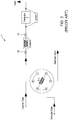
- a simple gas chromatography (GC) system 1 is shown.
- the dead volume is present on both sides of the column since there is a fitting 10 on each end of the column.
- These dead volumes become problematic when there is a low carrier flow. Indeed, this will generate chromatographic peak broadening. Problems caused by scratches and generated particles are relatively easy to detect. However, problems caused by dead volumes are much more subtle, and can sometimes be mistakenly identified as leaks. In fact, dead volumes are often referred to as virtual leaks.
- a sample gas 4 is injected on a separation column to separate the impurities and then to measure them by the integration of successive signal peaks by the detector 2, as well known in the art.
- the sample loop is swept by the sample gas 4, while the separation column and the detector 2 are swept by the carrier gas 3.
- the carrier 3 is helium
- the column has an outer diameter (OD) of 1/8"
- a molecular sieve is used
- the detector 2 is of the helium ionisation type.
- Each side of the column is provided with a double ferrule fitting 10, similar to the one illustrated in Figure 1A . After starting up the system 1, helium is circulated and the column is regenerated to purge away any contaminants.
- Figures 3 and 4 are graphs showing the level of impurities in parts per million (ppm) detected as function of the time in minutes.
- Figure 3 shows the signal of the detector of the system 1 from Figure 2 , after the system has stabilized, while
- Figure 4 shows the effect of varying the flow of the carrier on the detecting signal.
- the variation consists of decreasing the flow of the carrier and then of restoring it.
- carrier flow is decreased, the signal increases due to the presence of accumulated gas in the dead volumes, this accumulated gas diffusing back into the carrier.
- the presence of accumulated gas in the carrier increases the impurity level into the detector, thus increasing the detecting signal.
- the ferrules By retightening the fittings, the ferrules are pushed forward in the body of the fitting and the outer diameter of the tubing increases once again, thus decreasing the dead volume. By doing so, the entrapped contaminant is forced back into the carrier gas and detector.
- the signal shown illustrates the result of this action. Varying the flow or pressure to crosscheck for leaks would again generate a signal similar to the one illustrated in Figure 4 , but with less amplitude. Again, with the best intention in mind, an operator observing this would once again retighten the fittings, believing there are still leaks. The fact that there are also unions and other fittings at various locations in the system makes this problem even more difficult to track, identify and resolve. In the end, in attempting to resolve these virtual leaks, fittings will become over-tightened, and real leaks can be generated.
- US 2001/0054821 describes a double ferrule fitting which includes a body having a bore for receiving a tube end, a drive member having threaded engagement with the body, and first and second ferrules having tapered ends.
- the fitting includes a vent in the form of a hole in the drive member to relieve pressure when the drive member is at least partly loosened from the body.
- US 3,584,900 describes a fitting for a conduit having a frustoconical forwardly converging sealing surface.
- the fitting includes a coupling body, front and back ferrules, and a coupling nut.
- the ferrules Upon application of compressive force by the coupling nut, the ferrules are deformed into gripping engagement with the conduit.
- a bleed passage is provided in the coupling body to conduct high pressure fluid to atmosphere rather than into the vicinity of the ferrules where the conduit could be subject to much greater end thrust.
- FIG. 6, 6A and 6B show a single ferrule fitting assembly 100 commonly used in gas chromatography systems.
- the single ferrule 112 used in such an assembly 20 does not cause a "swaging" action, and the extremity of the tube 114 does not bulge out for holding the tube 114 in place in the body of the fitting 116.
- the front edge of the ferrule 112 will grip the tube 115, creating a first sealing area.
- Another sealing point 115 is obtained between the external surface of the ferrule 112, and the internal surface of the fitting 116.
- the torque required to screw the nut 117 and push the ferrule 112 frontward in the fitting 116 is generally smaller than the torque required in the double ferrule design.
- the single ferrule fitting minimizes the formation of a dead volume precisely because the deformation of the tube 114 is reduced or eliminated.
- its diameter In order to prevent the tube 114 from being deformed, its diameter must be small enough so that the tube 114 can be slipped and fitted just tightly enough in the inner section of the fitting.
- the end of the tube 114 must be cut orthogonally, and have a clean and neat finish, in order to create a proper sealing surface with the corresponding squared bottom of the fitting.
- Single ferrule fittings generally provide adequate results when the tubing size is smaller than 1/8"OD. As such, these fittings are sometimes referred to as "zero dead volume” fittings. However, a dead volume is still present in the fitting when in use, even if it is a small one. In particular applications, where high sensitivity systems are used, such as mass spectrometers and plasma emission detectors, the effect of small dead volumes can be observed.
- the dead volume 119a corresponds to the clearance between the outside diameter of the tube 114 and the internal surface of the aperture of the fitting 116.
- This dead volume 119a no matter how small, will eventually be filled with fluid.
- the diameter of the molecule of Helium is about 0.25nm, Helium being a carrier commonly used in analytical systems.
- US 2003/0197378 describes a compression connector for sealingly connecting a fluid line to a plumbing fitting.
- a compression ferrule and a compression nut are coaxially mounted to the tubing.
- the compression ferrule includes wedge-like edges at both leading and trailing edges. As the nut is rotated, the leading and trailing edges of the ferrule are deflected radially inward into engagement with the tubing.
- An object of the present disclosure is to provide a fitting assembly addressing at least one of the above-mentioned needs.
- a fitting assembly includes a fitting component, a tube, ferrules and a nut.
- the tube has a tube end for insertion through the nut and ferrule, and a fit-in end corresponding to a portion of the tube end extending past the ferrule.
- the tube is securable to the fitting component via the ferrule and nut.
- the fitting component includes a fitting component body having first and second extremities.
- the fitting component body includes a cavity for receiving the tube end and the ferrule.
- the cavity is defined by inner lateral walls and opens on the first extremity of the body.
- the cavity includes a fit-in receiving section for receiving the fit-in end of the tube.
- the body also includes a channel in fluid communication with the cavity.
- the channel has a diameter smaller than a diameter of the fit-in receiving section.
- a radial annular flange is located at an interface of the fit-in receiving section with the channel.
- the flange has an annular sealing lip protruding towards the cavity, the sealing lip being coated with an inert substance and being for forming a seal with a radial surface of the fit-in.
- the fitting assembly is for use in an analytical system, to secure a tube.
- the fitting assembly comprises the fitting component, a front ferrule and a rear ferrule and the nut for securing the tube to the fitting component.
- the fitting component receives an end of the tube,
- the fitting component has a fitting component body comprises inner lateral walls that define a cavity extending axially through the fitting component body.
- the cavity has a tube-receiving section open at a first end (or outer end) for receiving the end of the tube therein; and a radial annular flange at a second end (or inner end) of the cavity for abutting a rim of the end of the tube.
- the front and rear ferrules are ring-shaped with a central bore sized to receive the tube there-through.
- the nut secures the tube to the fitting component and engages with the fitting component, biasing the front and rear ferrules to deform the tube.
- the nut has a nut body with first and second ends which are preferably proximate the first and second end of the fitting component.
- the nut body comprises an inner sidewall and an outer sidewall extending between the first and second ends, the inner sidewall defining a bore opening at the first and second ends.
- the bore is sized to receive the tube therethrough.
- the nut also comprises a fitting interface at its first end for engaging with the fitting component, a tube interface at its second end for fitting around the tube, and a channel (224) extending through the nut body, between the inner sidewall and the outer sidewall, said channel providing a path for fluid between the bore and an exterior of the nut body, said channel being provided with a sealing element.
- a leak chamber is defined in a space between the tube, the fitting component and the inner sidewall of the nut body, the leak chamber being in fluid communication with the exterior of the nut body via the channel in the nut body, where the sealing element seals the channel (224) to contain leaks and allow pressure to build up in the leak chamber (226).
- the fitting assembling includes a front ferrule and a rear ferrule compressed between the nut and the fitting component.
- the front ferrule is biased so as cause a deformation of the tube between the front ferrule and the channel of the fitting component body.
- the tube, nut and fitting component together define a leak chamber adjacent an interface of the tube and the fitting component.
- a sniffing hole is provided through the nut body or through the fitting component body for allowing fluid communication between the leak chamber and an exterior of the fitting assembly for facilitating leak detection.
- a septum is provided in the sniffing hole for containing gases in the leak chamber and for allowing leaked gases to accumulate therein.
- the septum can be configured to allow insertion of a probe therethrough.
- the nut includes a nut body with inner and outer nut sidewalls extending between a fitting interface end and a tube interface end, the inner sidewalls defining a bore.
- the sniffing hole includes a sniffing channel extending through the inner and outer nut sidewalls and fluidly communicating with the cavity.
- the sniffing channel is sloped upwards away from the fitting interface end.
- the fitting assembly further comprises a sealing element between the nut and the tube for containing leaks within the leak chamber and encouraging a leak flow path through the sniffing hole.
- the sealing element is a sealing ring provided along the inner nut sidewall.
- a fitting assembly kit includes a combination of at least some of the above-described fitting component, tube, ferrule and nut.
- a fitting component includes a body with a first end and a second end. At least one of the first and second ends is configured to receive a tube, ferrule and nut, and to form a leak chamber therewith.
- a sniffing hole is provided in the fitting component body for allowing fluid communication between the leak chamber and an exterior of the fitting component.
- a nut comprising a body with a tube interface end, a fitting component interface end, and a bore extending therethrough.
- the bore is shaped to receive a tube therethrough, receive a ferrule and an end of a fitting component therein, and form therewith a leak chamber.
- a sniffing hole is provided in the nut body for allowing fluid communication between the leak chamber and an exterior of the nut.
- the nut comprises inner sidewalls defining the bore, the inner sidewalls comprises a threaded portion for interfacing with a threaded section of the fitting component, and a non-threaded section for forming the leak chamber.
- the sniffing hole comprises a channel extending through the nut body and opening on the inner sidewalls of the nut in the non-threaded section.
- a method for detecting a leak in a fitting assembly is provided.
- a tube is secured in a fitting component.
- the tube is secured via a nut, the tube extending through a central bore in the nut, and the nut engaging with the fitting component to bias an end of the tube towards the fitting component.
- fluid is passed through the tube.
- a fluid leaking is directing from an interface between the end of the tube and the fitting component into a leak chamber in an interior portion of the nut, by sealing an interface between the tube and the nut and by sealing an interface between the nut and the fitting component and by temporarily sealing the channel.
- the fluid from the leak chamber is sampled via the channel and a determination is made whether the fluid sampled from the leak chamber contains traces of the fluid passed through the tube, the presence of said traces indicating the existence of the leak in the fitting assembly.
- the fitting assembly described herein combines the analytical performance of a lip-seal fitting assembly with the mechanical robustness of a "swaging" fitting assembly. This allows for a single type of fitting to be used in both analytical and industrial applications.
- the components of the fitting assembly are shaped, sized and configured to create a leak chamber defined in a space between the tube, the fitting component and the inner sidewall of the nut body.
- the leak chamber is in fluid communication with the channel provided in the nut, and can be closed by placing a septum or other similar plug in the channel, or it can be connected to an analytical detector to detect impurities and sample molecules trapped in the leak chamber.
- the present invention is particularly adapted in analytical systems, for tube diameters varying from 1/16"OD to 1/8"OD.
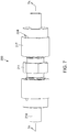
- a fitting assembly 200 is shown according to an embodiment.
- the described fitting assembly 200 is a union-type fitting, it should be understood that the features of the improved fitting assembly described herein can apply to other types of fitting assemblies or any component part of an analytical system which is adapted to receive a tube locked in place with a compression nut and a ferrule, such as a cap, a valve, a valve cap, a valve body, a sealing plate, an instrument body or frame, an analyzer, sampler or separation module, a sample panel, a fluidic control component, an actuating mechanism and the like.
- the fitting assembly 200 includes a fitting component 216, a tube 214, front and rear ferrules 212a, 212b and a nut 217.
- the tube 214 is secured to the fitting component 216 by the nut 217.
- the front and rear ferrules 212a, 212b are compressed between the fitting component 216 and the nut 217, causing a swaging 213 of the tube 214 in front of the front ferrule 212a.
- the tube 214 is deformed in front of the front ferrule 212a such that its diameter is greater than that of the aperture of the ferrules 212a, 212b through which it was inserted.
- the tube 214 is thus secured inside the fitting component 216 and is able to resist high pressure and vibration.
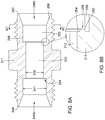
- the fitting component 216 comprises a fitting component body 211 with inner lateral walls 248 defining a fitting component cavity 246.
- the fitting component cavity 246 has a tube receiving section 250 with a tube receiving section diameter 241, the tube receiving section 250 being sized and configured to receive a tube 214 therein.
- the inner lateral walls 248 include a tapered section 258 for receiving the front ferrule 212a and biasing it towards the tube 214 as the nut 217 is tightened.
- the fitting component body 211 of the union-type fitting component 216 has first and second ends 242, 244 with a threaded connection 218 for receiving and securing a nut 217.
- the threaded connection 218 is precisely machined and is provided with a surface treatment such as silver.
- the inner lateral walls 248 define first and second cavities 246a, 246b which respectively open in the first and second ends 242, 244.
- the cavities 246a, 246b are in fluid communication via a channel 220 extending through the body 211, thus allowing for a fluid communication between tubes 214 respectively secured to the first and second ends 242, 244 of the fitting component 246.
- the channel 220 has a channel diameter 239 which is preferably smaller than the tube receiving section diameter 241.
- the fitting component body 211 comprises a radial annular flange 254 at an end of the tube receiving section 250, where the tube receiving section 250 meets the channel 220.
- the annular flange 254 has a radial thickness corresponding to the difference between the tube receiving section diameter 241 and the channel diameter 239.
- the cavities 246a and 246b have the same tube receiving section diameter 241, it should be appreciated that in other embodiments their tube receiving section diameters can differ, for example in a reducing fitting component for joining first and second tubes, the second tube having an outer diameter smaller than the outer diameter of the first tube.
- the channel 220 has a uniform channel diameter 239, in alternate embodiments, the channel diameter 239 can vary along the length of the channel 220.
- the tube 214 has tube sidewalls 235 defining an inner diameter 238 and an outer diameter 240.
- the tube 214 has a tube end 234 for insertion through the nut 217 and ferrules 212a, 212b, and a fit-in end 236 which is a portion of the tube end 234 extending past the front ferrule 212a.
- the tube end 234 is first inserted through the nut 217 and the ferrules 212a and 212b..
- the nut 217 is then tightened, causing the ferrules 212a, 212b to compress and deform the tube sidewalls 235.
- the fit-in end 236 has a radial surface 237 for interfacing with the annular flange 254 of the fitting component body 211.
- the inner diameter 238 of the tube 214 corresponds to the channel diameter 239, thus creating a uniform flow path for gas travelling through the tube 214 and channel 220, and avoiding dead volume.
- the outer diameter 240 of the tube 214 can also correspond to the tube receiving section diameter 241 to further reduce dead volume and ensure a proper seal.
- the radial annular flange 254 is provided with an annular sealing lip 256 which protrudes towards the cavity 246.
- the sealing lip 256 is for interfacing with the radial surface 237 of the tube 214 and creating a seal therewith.
- the sealing lip 256 can be coated with an inert substance 262 softer than the material from which the fitting component body 211 is made.
- the inert substance 262 is gold.
- the sealing lip 256 allows for a better seal to be created between the tube 214 and the fitting component body 211.
- the ferrules 212a and 212b are compressed and grip the tub 214.
- the radial surface 237 of the tube 214 is compressed against the annular sealing lip 256.
- the sealing lip 256 is preferably fine so that it distributes the mechanical force on a small area and increases the effective seating force.
- the tube 214 is made of a material which is softer than the material forming the fitting component body 211.
- the tube 214 can be made of annealed SS304, while the fitting component body 211 can be made of hardened SS316L.
- the sealing lip 256 penetrates the radial surface 237 of the tube 214 and creates a strong metal-to-metal seal therewith.
- the sealing lip 256 is a rounded bump, however it should be understood that in alternate embodiments, the sealing lip 256 can take different shapes to better interface with the radial surface 237 of the tube 214.
- the sealing lip 256 can comprise one or more sharp peaks or ridges, or can be textured to better grip or penetrate the radial surface 237.
- the sealing lip 256 reduces the amount of torque required to create an effective seal, which can be nearly finger tight.
- a fitting with a sealing lip and double ferrule such as the one shown in Figure 7 and described herein-above, requires significantly less force (just over 20 Ib-in) to achieve an adequate sealing force compared to a double ferrule fitting of the prior art (in excess of 50 Ib-in), such as the one shown in Figure 1 . Since less torque is required to create an effective seal, the amount of swaging or deformation of the tube can be reduced. The tube can therefore be more easily removed once the nut is loosened.
- a sealing lip in a double ferrule fitting is advantageous because the resulting fitting is suitable for a wide range of applications.
- single ferrule fittings with a sealing lip were preferred for analytical systems due to their reduction of dead volume and tight seal.
- double ferrule fittings are less desirable for such applications because they are known to suffer from dead volume issues.
- double ferrule fittings are preferred due to the robustness achieved from the "swaging" of the tube, making them resistant to vibration and high pressure.
- the improved double ferrule fitting assembly disclosed herein combines the robustness of a double ferrule fitting with the analytical performance of a single ferrule fitting. The improved fitting assembly therefore allows for a single type of fitting to be used in both analytical systems and industrial applications, making it commercially advantageous.
- the nut 217 comprises a nut body 223 with a fitting interface end 231 and a tube interface end 233, delimited by terminal faces 249.
- the nut body 223 comprises inner and outer nut sidewalls 227, 229 extending between the terminal faces 249, the inner sidewall 227 defining a bore 225 which opens at the fitting interface end 231 and the tube interface end 233.
- the fitting interface end 231 is configured to fit around the threaded connection 218 on an end 242, 244 of the fitting component body 211, while the tube interface end 233 is configured to fit around the tube sidewalls 235.
- the inner nut sidewall 227 therefore has an inner diameter in the fitting interface end 257 sized to accommodate an end 242, 244 of the fitting component body 211, and an inner diameter in the tube interface end 255 sized to accommodate the tube 214.
- the inner nut sidewall 227 also has a threaded portion 263, and may also have a non-threaded portion 264.
- the threaded portion 263 is precisely machined and is provided with a surface treatment such as silver, and thereby creates a sufficient seal when engaged with the threaded connection 218 of the fitting component body 211.
- the inner sidewall of the nut body comprise the threaded section 263 in a fitting interface end for engaging around a corresponding threaded section in the fitting component body.
- the inner diameter in the fitting interface end 257 is larger than the inner diameter in the tube interface end 255; however these diameters can vary depending on the configuration of the fitting assembly.
- the outer nut sidewall 229 has an outer diameter in the fitting interface end 252 and an outer diameter in the tube interface end 251.
- the outer diameter in the fitting interface end 252 is preferably larger than the outer diameter in the tube interface end 251.
- the outer nut sidewall 229 is also sized and shaped to interface with and be tightened by a wrench or other similar tool.
- the outer walls of the nut body comprise a profiled section in the fitting interface end for cooperating with a tightening tool, and a non-profiled section in the tube interface end.
- the channel in the nut body extends between the inner sidewalls and the non-profiled section of the outer sidewalls in the nut body.
- the tube 214 When assembled, the tube 214 passes through the bore 255 and out through the tube interface end 233.
- the fitting interface end 231 receives the ferrules 212a, 212b and the fitting 216, and attaches to the fitting component 216 via a threaded connection 218.
- the nut 217 defines together with the fitting component 216 and tube 214 a leak chamber 226.
- the leak chamber 226 will fill up with gas.
- the nut sidewalls 227 comprise a non-threaded portion 264 for helping to form the leak chamber 226.
- a sniffing hole 224 is provided to allow detection of gas building up in the leak chamber 226, and thus facilitate the detection of leaks.
- the sniffing hole 224 is configured to allow fluid communication between the leak chamber 226 and an exterior of the fitting assembly 200.
- the sniffing hole is a channel 224 which extends through the nut body 223, and provides a fluid path between the leak chamber 226 and an exterior of the nut 217.
- the channel 224 slopes along the length of the nut 217, upward from the fitting interface end 231 towards the tube interface end 233. In an alternate embodiment, however, the channel 224 can have a different orientation.
- the channel can be sloped in the opposite direction, can be vertical, or can be sloped substantially tangent to the circumference of the nut 217.
- the channel 224 is round.
- the channel can have a different shape, for example to accommodate or secure different types of measuring tools.
- the channel 224 is straight.
- the channel 224 can be curved or shaped otherwise to create a more complex path for leaking gas, or to accommodate or secure different types of measuring tools.
- the channel in the nut body open as a sniffing hole on the outer sidewalls of the nut body, the sniffing hole being positioned proximate to a junction of the fitting interface end and the tube interface end.
- the channel in the nut body extends at an oblique angle relative to the bore in the nut body.
- the channel 224 opens on one end in the bore 225 in the fitting interface end 231 of the nut body 223 and on the other end on the outer nut sidewall 229 where the fitting interface end 231 meets the tube interface end 233.
- the channel 224 can open elsewhere.
- the channel can open on the outer nut sidewall 229, exclusively in one of the fitting interface end 231 and the tube interface end 233 of the nut body 223.
- the channel can open on one of the terminal faces 249 of the nut instead of along the nut sidewall 229.
- the channel 224 opens in the bore 225 in a non-threaded portion 264 of the inner nut sidewalls 227.
- the channel 224 can open on the inner walls 227 where they are threaded 263.
- the channel 224 can further be provided with a gate or sealing element to help contain leaks, allow pressure to build up in the leak chamber 226, and/or create a seal with an input of a measuring instrument, such as a capillary tube inserted into the channel for example.
- a measuring instrument such as a capillary tube inserted into the channel for example.
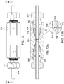
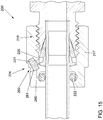
- FIG 15 an alternate embodiment of a fitting assembly 200' is shown, where the nut 217 is provided with a septum 221 along the channel 224.
- the septum 221 is preferably a disk-shaped element which is received inside a septum receiving cavity 265 along the channel 224 in the nut 217.
- the septum 221 is made of a material impermeable to gas and serves to temporarily seal the channel 224.
- the septum is pierceable for allowing a probe (or a needle, syringe, capillary tube or the like) to pass therethrough.
- the septum 221 is self-sealing so that when the probe is inserted, a seal is created around said probe.
- the septum 221 closes and seals the channel 224.
- the septum 221 can be made of a resilient material, such as rubber, and can be provided with a self-sealing central aperture.
- the septum 221 allows containing low pressure leaks inside the leak chamber 226, which can be particularly useful when dealing with toxic gases where even a small leak from the fitting assembly 200 can be a health hazard.
- the septum 221 is removably inserted in the channel 224.
- the channel 224 is provided with a widened portion 260 adjacent the cavity 265 for inserting the septum 221.
- the widened portion 260 is narrower than a diameter of the septum 221, requiring the septum to be deformed as it is inserted.
- the cavity 265 can be wider than the widened portion 260 of the channel 224, thus allowing the septum 221 to expand, and providing a lip 261 against which the septum 221 can abut.
- the septum 221 can be held in place as pressure builds up in the leak chamber 226.
- the septum 221 can be held in the channel 224 by other means.
- the channel has the widened portion 260 proximate the outer sidewall 229 of the nut body for receiving the septum 221 therein.
- the widened portion has its inner diameter greater than its inner diameter of the channel 224 proximate the inner sidewall 227 of the nut body.
- the fitting assembly comprises the septum cavity 265 positioned along the channel 224 for receiving the septum 221 therein, the inner diameter of the cavity being greater than an inner diameter of the channel, requiring the septum 221 to be deformed to be inserted or removed from the cavity 265.
- the septum is preferably pierceable and self-sealing.
- the septum is made of a resilient material, such as rubber or an elastomer, for example.
- a removable cap (not illustrated) can also be provided for closing the channel 224 when not in use.
- the cap can be made of metal, plastic, rubber, or any other suitable material, and can be press fit or screwed into the channel 224.
- the sniffing hole 524 can extend through the fitting body 511.
- the sniffing hole 524 can take a different shape, orientation, or can open on a different face of the fitting body 511.
- the fitting assembly can include a sealing element 222 for containing gas leaks in the chamber 226.
- the sealing element is a sealing ring 222 provided in the tube interface end 233 of the nut 217; the nut 217 comprises a seal chamber 253 for housing the sealing ring 222.
- the sealing ring 222 is positioned such that it creates a seal between the nut 217 and the tube sidewalls 235.
- the sealing ring 222 can be made of any suitable sealing material such as rubber or plastic.
- the sealing element 222 is provided in the tube interface end 233 of the nut 217, it should be understood that it can be located elsewhere so long as it contains leaks to the chamber 226.
- the sealing ring 222 can additionally or alternatively be provided along the sniffing hole 224.
- the leak chamber comprises a annular region 226, on which the channel 224 opens.
- the rear ferrule preferably has an annular rim facing the back wall of the nut, and a annular ring surrounding the tube.
- the annular region 226 surround the rear ferrule and is at least partly delimited by a space between the rim the rear ferrule, and the back side of the front ferrule.
- the sealing element 522 can be provided at an end of the nut 517 proximate to the chamber 526.
- the fitting assembly comprises the sealing ring in the tube interface of the nut body, for sealing the interface between the tube and the nut and to prevent fluid in the leak chamber from escaping there-through.
- the described configuration facilitates detection of leaks.
- gas leaking from the channel 220 will be contained in the leak chamber 226 by the sealing ring 222. Gas leaks will therefore be encouraged to follow a path 228 which exists through the sniffing hole 224.
- a probe 230 such as a helium detector, can be used to detect such leaks.
- a capillary tube 232 can be inserted into the sniffing hole 224 for sampling gas travelling through the leak path 228.
- a gas detector can be positioned outside the sniffing hole 224 and configured to detect gas exiting therefrom.
- the provision of the septum 221 can further facilitate the detection of leaks.
- the fitting assembly includes the septum 221 in the channel of the nut body, the septum sealing the channel to prevent fluid in the leak chamber from escaping there-through, while allowing insertion of a probe for detecting fluid in the leak chamber.
- the sealing action of the septum 221 together with the sealing action of the sealing element 222 and the threaded connection 218 allow for pressure to build up in the leak chamber 226.
- the sealing action of the septum 221 prevents outside gases from entering the leak chamber 226 through the channel 224, thereby creating an isolated atmosphere in the leak chamber 226. This allows for a probe to more easily and more effectively detect gases in the leak chamber 226 corresponding to leaks from the channel 220.
- the union-type fitting component has a first end and a second end, the cavity in the fitting component being provided in the first end thereof and comprising a channel 220 (best shown in Figure 8A ) connects the cavity in the first end to a cavity in the second end of the fitting component.
- the fitting assembly 300 shown is provided with a tube extending from the first extremity 342.
- the fitting assembly 300 can be used as an adaptor, the tube extending from the body of the fitting component being for connecting to another device.
- the fitting assembly 400 shown can be used as a cap, which is sometimes referred to as a plug.
- the first extremity 442 is closed, for capping a tube end.
- fitting components of the fitting assemblies 200, 300 and 400 of Figures 7 to 13B are shown with an elongated body and two extremities 242, 244, 342, 344, 442, 444
- other embodiments of the fitting assemblies can be provided with different shapes, such as a T-shape or an X-shape, and a fitting component can include more than two extremities, and more than two cavities.
- Fitting components according to the present invention can also be provided with a threaded joint on one side and with a soldered joint on the other side.
- the components of the fitting assembly as described above define a leak chamber that can be pressurized, to facilitate analysis of its content, to detect potential leaks.
- the leak chamber is preferably sealed at least at the proximal / front end of the tube by an annular lip, and also preferably at the distal / back end of the tube with a sealing ring provided in the rear end of the fitting, sealing ring surrounding the tube.
- a septum can be provided in the channel, such as for example to contains potential leaks when the channel is not connected to a probe at its outer end.
Landscapes
- Engineering & Computer Science (AREA)
- General Engineering & Computer Science (AREA)
- Mechanical Engineering (AREA)
- Physics & Mathematics (AREA)
- General Physics & Mathematics (AREA)
- Examining Or Testing Airtightness (AREA)
- Sampling And Sample Adjustment (AREA)
Claims (15)
- Montage-Anordnung (200) zur Verwendung in einem Analysesystem, wobei die Montage-Anordnung zur Befestigung eines Rohrs dient und umfassend:- eine Montagekomponente (216) zur Aufnahme eines Endes des Rohrs (214), wobei die Montagekomponente einen Montagekomponentenkörper (211) aufweist, umfassend:∘ innere Seitenwände (248), die einen Hohlraum (246) definieren, der sich axial durch den Körper erstreckt, wobei der Hohlraum einen Rohraufnahmeabschnitt (250) aufweist, der an einem ersten Ende (242) offen ist, um das Ende des Rohrs darin aufzunehmen; und∘ einen radialen ringförmigen Flansch (254) an einem zweiten Ende des Hohlraums zum Anlegen an einen Rand des Rohrendes; und- eine vordere Klemmhülse (212a) und eine hintere Klemmhülse (212b), wobei die vordere und die hintere Klemmhülse ringförmig sind und eine zentrale Bohrung aufweisen, die so bemessen ist, dass sie das Rohr durch sie hindurch aufnehmen können; wobei die Montageanordnung (200) dadurch gekennzeichnet ist, dass sie eine Mutter (217) zum Befestigen des Rohrs an der Montagekomponente umfasst, wobei die Mutter mit der Montagekomponente in Eingriff steht und die vordere und die hintere Klemmhülse vorspannt, um das Rohr zu verformen, wobei die Mutter einen Mutterkörper (223) mit einem ersten und einem zweiten Ende aufweist, wobei der Mutterkörper Folgendes umfasst:wobei, wenn die Mutter das Rohr an der Montagekomponente sichert, eine Leckkammer (226) in einem Raum zwischen dem Rohr, der Montagekomponente und der inneren Seitenwand des Mutterkörpers definiert ist, wobei die Leckkammer über den Kanal (224) in dem Mutterkörper in Fluidverbindung mit der Außenseite des Mutterkörpers steht, wobei ferner das Dichtungselement den Kanal (224) abdichtet, um Lecks einzudämmen und einen Druckaufbau in der Leckkammer (226) zu ermöglichen.∘ eine innere Seitenwand (227) und eine äußere Seitenwand (229), die sich zwischen dem ersten und dem zweiten Ende erstrecken, wobei die innere Seitenwand eine Bohrung (225) definiert, die sich an dem ersten und dem zweiten Ende öffnet, wobei die Bohrung so bemessen ist, dass sie das Rohr dort hindurch aufnimmt;∘ eine Anpassungsschnittstelle (231) am ersten Ende zum Eingreifen in die Anpassungskomponente;∘ eine Rohrschnittstelle (233) am zweiten Ende zum Einpassen rund um das Rohr; und∘ einen Kanal (224), der sich durch den Mutterkörper zwischen der inneren Seitenwand und der äußeren Seitenwand erstreckt, wobei der Kanal einen Weg für Fluid zwischen der Bohrung und einer Außenseite des Mutterkörpers bereitstellt, wobei der Kanal mit einem Dichtelement versehen ist;
- Montage-Anordnung nach Anspruch 1, die ferner einen Dichtungsring (222) in der Rohrschnittstelle des Mutterkörpers umfasst, um eine Schnittstelle zwischen dem Rohr und der Mutter abzudichten und zu verhindern, dass Fluid in der Leckkammer durch diese hindurch austritt.
- Montage-Anordnung nach Anspruch 1 oder 2, wobei das Dichtungselement ein Septum (221) im Kanal des Mutterkörpers umfasst, wobei das Septum den Kanal abdichtet, um zu verhindern, dass Fluid in der Leckkammer durch ihn hindurch austritt, während es das Einführen einer Sonde zum Erfassen von Fluid in der Leckkammer ermöglicht.
- Montage-Anordnung nach Anspruch 3, die ferner einen Septumhohlraum (265) umfasst, der entlang des Kanals (224) positioniert ist, um das Septum (221) darin aufzunehmen, wobei ein Innendurchmesser des Hohlraums größer ist als ein Innendurchmesser des Kanals, sodass das Septum (221) verformt werden muss, um in den Hohlraum (265) eingesetzt oder daraus entfernt zu werden.
- Montage-Anordnung nach Anspruch 3 oder 4, wobei das Septum durchstechbar und selbstdichtend ist.
- Montageanordnung nach einem der Ansprüche 1 bis 5, wobei die innere Seitenwand des Mutterkörpers einen Gewindeabschnitt (263) in einem Montageschnittstellenende zum Umgreifen eines entsprechenden Gewindeabschnitts im Montagekomponentenkörper aufweist.
- Montage-Anordnung nach Anspruch 6, wobei der Gewindeabschnitt der inneren Seitenwand mit Silber beschichtet ist.
- Montage-Anordnung nach Anspruch 6 oder 7, wobei die innere Seitenwand des Mutterkörpers ferner einen gewindelosen Abschnitt (264) im Verschraubungsschnittstellenende, angrenzend an das Rohrschnittstellenende, aufweist.
- Montage-Anordnung nach Anspruch 8, wobei sich der Kanal im Mutterkörper zwischen dem gewindelosen Abschnitt der inneren Seitenwand und der äußeren Seitenwand des Mutterkörpers erstreckt.
- Montage-Anordnung nach einem der Ansprüche 1 bis 9, wobei sich der Kanal im Mutterkörper zwischen der inneren Seitenwand im Verschraubungsanschlussende und der äußeren Seitenwand im Rohranschlussende erstreckt.
- Montage-Anordnung nach einem der Ansprüche 1 bis 10, wobei sich der Kanal im Mutterkörper als Schnüffelloch an der äußeren Seitenwand des Mutterkörpers öffnet, wobei das Schnüffelloch in der Nähe einer Verbindung zwischen dem Montageschnittstellenende und dem Rohrschnittstellenende angeordnet ist.
- Montage-Anordnung nach einem der Ansprüche 1 bis 11, wobei der Kanal im Mutterkörper in einem schrägen Winkel zur Bohrung im Mutterkörper verläuft.
- Montage-Anordnung nach einem der Ansprüche 1 bis 12, wobei die Montagekomponente eine Montagekomponente vom Union-Typ mit einem ersten Ende und einem zweiten Ende ist, wobei der Hohlraum in der Montagekomponente in deren erstem Ende vorgesehen ist und einen Kanal (220) umfasst, der den Hohlraum im ersten Ende mit einem Hohlraum im zweiten Ende der Montagekomponente verbindet.
- Montagekomponente nach Anspruch 13, wobei ein Innendurchmesser des Kanals (239) in der Montagekomponente kleiner ist als ein Innendurchmesser (241) des Rohraufnahmeabschnitts des Hohlraums in der Montagekomponente.
- Verfahren zum Erkennen eines Lecks in einer Armaturenbaugruppe (200) nach Anspruch 1, wobei das Verfahren dadurch gekennzeichnet ist, dass es die folgenden Schritte umfasst:a. Befestigen eines Rohrs (214) an einer Montagekomponente über eine Mutter, wobei sich das Rohr durch eine zentrale Bohrung in der Mutter erstreckt und die Mutter (217) mit der Montagekomponente in Eingriff steht, um ein Ende des Rohrs in Richtung der Montagekomponente vorzuspannen;b. Durchleiten von Flüssigkeit durch den Schlauch;c. Leiten von Fluid, das aus einer Grenzfläche zwischen dem Ende des Rohrs und der Montagekomponente austritt, in eine Leckkammer in einem inneren Abschnitt der Mutter, durch Abdichten einer Grenzfläche zwischen dem Rohr und der Mutter, durch Abdichten einer Grenzfläche zwischen der Mutter und der Montagekomponente und durch vorübergehendes Abdichten des Kanals (224);d. Probenahme von Fluid aus der Leckkammer über den Kanal; unde. Bestimmen, ob das aus der Leckkammer entnommene Fluid Spuren des durch das Rohr geleiteten Fluids enthält, wobei das Vorhandensein dieser Spuren auf das Vorhandensein des Lecks in der Montage-Anordnung hinweist.
Applications Claiming Priority (2)
| Application Number | Priority Date | Filing Date | Title |
|---|---|---|---|
| US201562215346P | 2015-09-08 | 2015-09-08 | |
| PCT/CA2016/051061 WO2017041175A1 (en) | 2015-09-08 | 2016-09-08 | Fitting assembly for analtical applications |
Publications (3)
| Publication Number | Publication Date |
|---|---|
| EP3338071A1 EP3338071A1 (de) | 2018-06-27 |
| EP3338071A4 EP3338071A4 (de) | 2019-10-09 |
| EP3338071B1 true EP3338071B1 (de) | 2021-03-10 |
Family
ID=58240494
Family Applications (1)
| Application Number | Title | Priority Date | Filing Date |
|---|---|---|---|
| EP16843330.8A Active EP3338071B1 (de) | 2015-09-08 | 2016-09-08 | Anschlussanordnung für analytische anwendungen |
Country Status (4)
| Country | Link |
|---|---|
| US (1) | US11067467B2 (de) |
| EP (1) | EP3338071B1 (de) |
| CN (1) | CN108700484B (de) |
| WO (1) | WO2017041175A1 (de) |
Families Citing this family (8)
| Publication number | Priority date | Publication date | Assignee | Title |
|---|---|---|---|---|
| WO2018217229A1 (en) * | 2017-05-21 | 2018-11-29 | Jms Southeast, Inc. | Process inserts, assemblies, and related methods for high velocity applications |
| US10781958B2 (en) | 2017-10-31 | 2020-09-22 | Oetiker Ny, Inc. | Low peak insertion tube end form |
| BR112023001975A2 (pt) * | 2020-08-05 | 2023-02-28 | Lps Ip Llc | Conexão de tubulação vedada, luva de tubulação, e vedações de tubulação traváveis e método de fabricação das mesmas |
| US12270492B2 (en) * | 2020-08-05 | 2025-04-08 | Lps Ip, Llc | Sealed pipeline connection and raised pipeline sleeve, and method of making same |
| US11231118B1 (en) * | 2020-11-10 | 2022-01-25 | Hanon Systems | Integrated one way valve |
| CN112879687B (zh) * | 2021-01-04 | 2022-12-06 | 华灿光电(苏州)有限公司 | 隔离挡板的检漏连接头及检漏方法 |
| CN113567109A (zh) * | 2021-07-26 | 2021-10-29 | 中国人民解放军总医院第八医学中心 | 一种安全阀检验装置 |
| CN114776901B (zh) * | 2022-06-17 | 2022-09-02 | 苏州谱测光电科技有限公司 | 一种密封性强的燃气管道接头 |
Family Cites Families (53)
| Publication number | Priority date | Publication date | Assignee | Title |
|---|---|---|---|---|
| US3134615A (en) * | 1960-10-24 | 1964-05-26 | Crawford Fitting Co | Tube fitting for large diameter tubing |
| US3069188A (en) * | 1961-01-26 | 1962-12-18 | Cullen B Crawford | Tube coupling |
| US3486775A (en) * | 1968-07-31 | 1969-12-30 | Cajon Co | Fitting |
| US3584900A (en) | 1968-09-18 | 1971-06-15 | Sno Trik Co | High-pressure sealing and gripping device |
| DE2458473A1 (de) * | 1973-12-21 | 1975-07-03 | Louis Martelli | Rohrverbindung |
| US4304422A (en) * | 1980-02-19 | 1981-12-08 | Gould Inc. | Tube coupling with frangible sleeve |
| US4422675A (en) * | 1981-07-29 | 1983-12-27 | United Technologies Corporation | Co-axial tube coupling |
| GB8603364D0 (en) * | 1986-02-11 | 1986-03-19 | Dunlop Ltd | Hose leak detectors |
| US4893846A (en) * | 1989-05-02 | 1990-01-16 | Mcgraw Doonan D | Connector fittings |
| US5217261A (en) * | 1990-04-23 | 1993-06-08 | Aeroquip Corporation | Flareless compression fitting |
| US5114190A (en) * | 1990-10-16 | 1992-05-19 | Parker Hannifin Corporation | Electrically insulated tube union |
| US5074599A (en) * | 1990-10-30 | 1991-12-24 | Crawford Fitting Co. | Tube fitting |
| US5388871A (en) * | 1992-05-22 | 1995-02-14 | Kakizaki Manufacturing Co., Ltd. | Fittings with box nuts |
| US5263312A (en) * | 1992-07-21 | 1993-11-23 | General Electric Company | Tube fitting for a gas turbine engine |
| JP2587449Y2 (ja) * | 1993-08-04 | 1998-12-16 | 日曹エンジニアリング株式会社 | 配管用継手機構 |
| US5482618A (en) * | 1994-07-19 | 1996-01-09 | Systems Chemistry, Inc. | Flow-through, in-line filter housing |
| US5735553A (en) * | 1996-03-08 | 1998-04-07 | Niemiec; Albin J. | Flared tube fitting for connecting flow conductors |
| US5904376A (en) * | 1997-01-29 | 1999-05-18 | Yuen; Po S. | Coupling assembly for a fluid purification system |
| US5882050A (en) * | 1997-04-15 | 1999-03-16 | Williams; Peter C. | Ferrule with relief to reduce galling |
| US7614668B1 (en) * | 1997-04-15 | 2009-11-10 | Swagelok Company | Ferrule with plural inner diameters |
| US6314795B1 (en) * | 1997-07-22 | 2001-11-13 | Ferret Technology Limited | Leak tracing |
| JP2001059663A (ja) * | 1999-08-20 | 2001-03-06 | Fujitsu General Ltd | 配管の接続装置 |
| US20010054821A1 (en) * | 2000-06-23 | 2001-12-27 | Volcansek Steven J. | Fitting with pressure relief vent |
| SE520508C2 (sv) * | 2001-11-15 | 2003-07-15 | Volvo Lastvagnar Ab | Kopplingsanordning för tryckmediumledningar och förfarande för framställning av sådan kopplingsanordning, innefattande läckagespår för indikering av läckage |
| US6851729B2 (en) * | 2001-12-07 | 2005-02-08 | Parker-Hannifin Corporation | Tube fitting for medium pressure applications |
| US20030197378A1 (en) * | 2002-04-18 | 2003-10-23 | Allstead Bradley E. | Sealing compression ferrule for plumbing connection fitting |
| US6889538B2 (en) * | 2003-10-02 | 2005-05-10 | Varco I/P, Inc. | Monitoring system for leak prevention and detection |
| US20080007050A1 (en) * | 2003-11-03 | 2008-01-10 | Williams Peter C | Fitting for metal pipe and tubing |
| TW200602577A (en) * | 2004-04-22 | 2006-01-16 | Swagelok Co | Fitting for tube and pipe |
| US7497483B2 (en) * | 2004-04-22 | 2009-03-03 | Swagelok Company | Fitting for tube and pipe with cartridge |
| CN2804548Y (zh) * | 2005-04-19 | 2006-08-09 | 阮浩丰 | 管接头 |
| US20070001448A1 (en) * | 2005-07-01 | 2007-01-04 | Ramon Navarro | Sanitary hose couplers |
| US8007013B2 (en) * | 2006-01-13 | 2011-08-30 | Swagelok Company | Fitting with adapted engaging surfaces |
| US7692553B2 (en) * | 2006-07-21 | 2010-04-06 | Deublin Company | Leak detecting system for rotating union |
| US8272671B2 (en) * | 2007-01-30 | 2012-09-25 | Airsept, Inc. | Fluid line connector |
| US20100320755A1 (en) * | 2007-06-26 | 2010-12-23 | Swagelok Company | Apparatus and method of zero clearance connection with optional sensing function |
| DE112008001699T5 (de) * | 2007-06-26 | 2010-06-10 | Swagelok Co., Solon | Leitungsverbindung mit Sensorfunktion |
| US20100140932A1 (en) * | 2007-07-27 | 2010-06-10 | Swagelok Company | Tapered nut for tube or pipe fitting |
| DE112008002088T5 (de) * | 2007-08-03 | 2010-09-09 | Swagelok Company, Solon | Ringzwingenanschluss mit drehmomentbasiertem Aufziehen |
| US20100194107A1 (en) * | 2007-08-09 | 2010-08-05 | Swagelok Company | Tube fitting |
| CN105065810B (zh) * | 2009-02-20 | 2018-06-12 | 斯瓦戈洛克公司 | 具有扭矩箍的导管配件以及用于拉近导管配件的方法 |
| WO2010129261A1 (en) * | 2009-04-27 | 2010-11-11 | Swagelok Company | Tapered drive nut for conduit fitting |
| US8931808B2 (en) | 2011-03-01 | 2015-01-13 | Idex Health & Science Llc | High pressure fitting with self-releasing ferrule |
| CA2770970C (en) * | 2011-03-08 | 2015-06-02 | Mecanique Analytique Inc. | Improved fitting component, ferrule and nut |
| CN202213801U (zh) * | 2011-08-29 | 2012-05-09 | 张永楼 | 一种便于检测的食品容器 |
| GB201204294D0 (en) * | 2012-03-12 | 2012-04-25 | Pioneer Lining Technology Ltd | Electrofusion fitting |
| WO2014014622A1 (en) * | 2012-07-17 | 2014-01-23 | Waters Technologies Corporation | High pressure fitting for supercritical fluid chromatography |
| BE1021364B1 (nl) * | 2013-12-17 | 2015-11-06 | Atlas Copco Airpower Naamloze Vennootschap | Koppeling voor het verbinden van buisuiteinden en overbrugging voor gebruik in een koppeling |
| EP3140580B1 (de) * | 2014-05-09 | 2020-03-25 | Swagelok Company | Leitungsverbindungsstück mit bauteilen zur leichteren montage |
| US10578503B2 (en) * | 2015-03-06 | 2020-03-03 | Swagelok Company | System and methods for strain detection in a coupling |
| WO2017165162A1 (en) * | 2016-03-23 | 2017-09-28 | Swagelok Company | Conduit fitting with stroke resisting features |
| US10520118B2 (en) * | 2017-05-11 | 2019-12-31 | Circor International | Tube fitting assembly |
| US11519529B2 (en) * | 2017-05-31 | 2022-12-06 | Hanon Systems | Metal sealing threaded (tube-o) fitting |
-
2016
- 2016-09-08 WO PCT/CA2016/051061 patent/WO2017041175A1/en not_active Ceased
- 2016-09-08 CN CN201680061857.1A patent/CN108700484B/zh active Active
- 2016-09-08 US US15/758,340 patent/US11067467B2/en active Active
- 2016-09-08 EP EP16843330.8A patent/EP3338071B1/de active Active
Non-Patent Citations (1)
| Title |
|---|
| None * |
Also Published As
| Publication number | Publication date |
|---|---|
| WO2017041175A1 (en) | 2017-03-16 |
| US11067467B2 (en) | 2021-07-20 |
| CN108700484A (zh) | 2018-10-23 |
| EP3338071A1 (de) | 2018-06-27 |
| US20180246003A1 (en) | 2018-08-30 |
| EP3338071A4 (de) | 2019-10-09 |
| CN108700484B (zh) | 2020-05-26 |
Similar Documents
| Publication | Publication Date | Title |
|---|---|---|
| EP3338071B1 (de) | Anschlussanordnung für analytische anwendungen | |
| CA2770970C (en) | Improved fitting component, ferrule and nut | |
| US8201854B2 (en) | Hybrid ferrule | |
| US5227059A (en) | Chromatography columns | |
| US6494500B1 (en) | Universal high pressure liquid connector | |
| US6162362A (en) | Direct screw-on cartridge holder with self-adjustable connection | |
| US5582723A (en) | Chromatography cartridge | |
| US20120319400A1 (en) | Fitting assembly | |
| GB2482175A (en) | Fitting element with bio-compatible sealing | |
| JP7282793B2 (ja) | ゼロ・デッドボリューム・フィッティングアッセンブリー | |
| JP2014513299A (ja) | 取付具アセンブリ | |
| US9482649B2 (en) | Fitting for elastically-biasing a capillary for a fluid-tight connection to a fluidic conduit | |
| JP2007078694A (ja) | 金属間シールを有する液体クロマトグラフィカラム | |
| US10527215B2 (en) | Adapter housing and connecting device for chromatography | |
| JP4909897B2 (ja) | 分離を実施するデバイス、方法、および装置 | |
| AU2019210710B2 (en) | Capillary fitting | |
| US10794877B2 (en) | Sorbent tube apparatus | |
| KR20140044347A (ko) | 자가 밀착식 배관 연결구 | |
| US12411114B2 (en) | Chromatography column adaptor and use for fluidic connections | |
| EP0328146A2 (de) | Säule für Hochdruck-Flüssigkeitschromatographie | |
| US20190030457A1 (en) | Packed bed |
Legal Events
| Date | Code | Title | Description |
|---|---|---|---|
| STAA | Information on the status of an ep patent application or granted ep patent |
Free format text: STATUS: THE INTERNATIONAL PUBLICATION HAS BEEN MADE |
|
| PUAI | Public reference made under article 153(3) epc to a published international application that has entered the european phase |
Free format text: ORIGINAL CODE: 0009012 |
|
| STAA | Information on the status of an ep patent application or granted ep patent |
Free format text: STATUS: REQUEST FOR EXAMINATION WAS MADE |
|
| 17P | Request for examination filed |
Effective date: 20180323 |
|
| AK | Designated contracting states |
Kind code of ref document: A1 Designated state(s): AL AT BE BG CH CY CZ DE DK EE ES FI FR GB GR HR HU IE IS IT LI LT LU LV MC MK MT NL NO PL PT RO RS SE SI SK SM TR |
|
| AX | Request for extension of the european patent |
Extension state: BA ME |
|
| DAV | Request for validation of the european patent (deleted) | ||
| DAX | Request for extension of the european patent (deleted) | ||
| R17P | Request for examination filed (corrected) |
Effective date: 20180323 |
|
| RIC1 | Information provided on ipc code assigned before grant |
Ipc: G01M 3/02 20060101AFI20190529BHEP Ipc: G01N 37/00 20060101ALI20190529BHEP Ipc: F16L 19/10 20060101ALI20190529BHEP Ipc: G01M 3/22 20060101ALI20190529BHEP Ipc: F16L 25/00 20060101ALI20190529BHEP Ipc: F16L 15/04 20060101ALI20190529BHEP |
|
| A4 | Supplementary search report drawn up and despatched |
Effective date: 20190909 |
|
| RIC1 | Information provided on ipc code assigned before grant |
Ipc: F16L 15/04 20060101ALI20190903BHEP Ipc: G01M 3/02 20060101AFI20190903BHEP Ipc: G01M 3/22 20060101ALI20190903BHEP Ipc: F16L 19/10 20060101ALI20190903BHEP Ipc: G01N 37/00 20060101ALI20190903BHEP Ipc: F16L 25/00 20060101ALI20190903BHEP |
|
| GRAP | Despatch of communication of intention to grant a patent |
Free format text: ORIGINAL CODE: EPIDOSNIGR1 |
|
| STAA | Information on the status of an ep patent application or granted ep patent |
Free format text: STATUS: GRANT OF PATENT IS INTENDED |
|
| INTG | Intention to grant announced |
Effective date: 20200423 |
|
| GRAJ | Information related to disapproval of communication of intention to grant by the applicant or resumption of examination proceedings by the epo deleted |
Free format text: ORIGINAL CODE: EPIDOSDIGR1 |
|
| STAA | Information on the status of an ep patent application or granted ep patent |
Free format text: STATUS: REQUEST FOR EXAMINATION WAS MADE |
|
| INTC | Intention to grant announced (deleted) | ||
| GRAP | Despatch of communication of intention to grant a patent |
Free format text: ORIGINAL CODE: EPIDOSNIGR1 |
|
| STAA | Information on the status of an ep patent application or granted ep patent |
Free format text: STATUS: GRANT OF PATENT IS INTENDED |
|
| INTG | Intention to grant announced |
Effective date: 20201005 |
|
| GRAS | Grant fee paid |
Free format text: ORIGINAL CODE: EPIDOSNIGR3 |
|
| GRAA | (expected) grant |
Free format text: ORIGINAL CODE: 0009210 |
|
| STAA | Information on the status of an ep patent application or granted ep patent |
Free format text: STATUS: THE PATENT HAS BEEN GRANTED |
|
| AK | Designated contracting states |
Kind code of ref document: B1 Designated state(s): AL AT BE BG CH CY CZ DE DK EE ES FI FR GB GR HR HU IE IS IT LI LT LU LV MC MK MT NL NO PL PT RO RS SE SI SK SM TR |
|
| REG | Reference to a national code |
Ref country code: GB Ref legal event code: FG4D |
|
| REG | Reference to a national code |
Ref country code: AT Ref legal event code: REF Ref document number: 1370346 Country of ref document: AT Kind code of ref document: T Effective date: 20210315 Ref country code: CH Ref legal event code: EP |
|
| REG | Reference to a national code |
Ref country code: IE Ref legal event code: FG4D |
|
| REG | Reference to a national code |
Ref country code: DE Ref legal event code: R096 Ref document number: 602016054182 Country of ref document: DE |
|
| REG | Reference to a national code |
Ref country code: LT Ref legal event code: MG9D |
|
| PG25 | Lapsed in a contracting state [announced via postgrant information from national office to epo] |
Ref country code: LT Free format text: LAPSE BECAUSE OF FAILURE TO SUBMIT A TRANSLATION OF THE DESCRIPTION OR TO PAY THE FEE WITHIN THE PRESCRIBED TIME-LIMIT Effective date: 20210310 Ref country code: BG Free format text: LAPSE BECAUSE OF FAILURE TO SUBMIT A TRANSLATION OF THE DESCRIPTION OR TO PAY THE FEE WITHIN THE PRESCRIBED TIME-LIMIT Effective date: 20210610 Ref country code: NO Free format text: LAPSE BECAUSE OF FAILURE TO SUBMIT A TRANSLATION OF THE DESCRIPTION OR TO PAY THE FEE WITHIN THE PRESCRIBED TIME-LIMIT Effective date: 20210610 Ref country code: HR Free format text: LAPSE BECAUSE OF FAILURE TO SUBMIT A TRANSLATION OF THE DESCRIPTION OR TO PAY THE FEE WITHIN THE PRESCRIBED TIME-LIMIT Effective date: 20210310 Ref country code: FI Free format text: LAPSE BECAUSE OF FAILURE TO SUBMIT A TRANSLATION OF THE DESCRIPTION OR TO PAY THE FEE WITHIN THE PRESCRIBED TIME-LIMIT Effective date: 20210310 Ref country code: GR Free format text: LAPSE BECAUSE OF FAILURE TO SUBMIT A TRANSLATION OF THE DESCRIPTION OR TO PAY THE FEE WITHIN THE PRESCRIBED TIME-LIMIT Effective date: 20210611 |
|
| REG | Reference to a national code |
Ref country code: AT Ref legal event code: MK05 Ref document number: 1370346 Country of ref document: AT Kind code of ref document: T Effective date: 20210310 |
|
| REG | Reference to a national code |
Ref country code: NL Ref legal event code: MP Effective date: 20210310 |
|
| PG25 | Lapsed in a contracting state [announced via postgrant information from national office to epo] |
Ref country code: RS Free format text: LAPSE BECAUSE OF FAILURE TO SUBMIT A TRANSLATION OF THE DESCRIPTION OR TO PAY THE FEE WITHIN THE PRESCRIBED TIME-LIMIT Effective date: 20210310 Ref country code: LV Free format text: LAPSE BECAUSE OF FAILURE TO SUBMIT A TRANSLATION OF THE DESCRIPTION OR TO PAY THE FEE WITHIN THE PRESCRIBED TIME-LIMIT Effective date: 20210310 Ref country code: SE Free format text: LAPSE BECAUSE OF FAILURE TO SUBMIT A TRANSLATION OF THE DESCRIPTION OR TO PAY THE FEE WITHIN THE PRESCRIBED TIME-LIMIT Effective date: 20210310 |
|
| PG25 | Lapsed in a contracting state [announced via postgrant information from national office to epo] |
Ref country code: NL Free format text: LAPSE BECAUSE OF FAILURE TO SUBMIT A TRANSLATION OF THE DESCRIPTION OR TO PAY THE FEE WITHIN THE PRESCRIBED TIME-LIMIT Effective date: 20210310 |
|
| PG25 | Lapsed in a contracting state [announced via postgrant information from national office to epo] |
Ref country code: CZ Free format text: LAPSE BECAUSE OF FAILURE TO SUBMIT A TRANSLATION OF THE DESCRIPTION OR TO PAY THE FEE WITHIN THE PRESCRIBED TIME-LIMIT Effective date: 20210310 Ref country code: EE Free format text: LAPSE BECAUSE OF FAILURE TO SUBMIT A TRANSLATION OF THE DESCRIPTION OR TO PAY THE FEE WITHIN THE PRESCRIBED TIME-LIMIT Effective date: 20210310 Ref country code: SM Free format text: LAPSE BECAUSE OF FAILURE TO SUBMIT A TRANSLATION OF THE DESCRIPTION OR TO PAY THE FEE WITHIN THE PRESCRIBED TIME-LIMIT Effective date: 20210310 Ref country code: AT Free format text: LAPSE BECAUSE OF FAILURE TO SUBMIT A TRANSLATION OF THE DESCRIPTION OR TO PAY THE FEE WITHIN THE PRESCRIBED TIME-LIMIT Effective date: 20210310 |
|
| PG25 | Lapsed in a contracting state [announced via postgrant information from national office to epo] |
Ref country code: SK Free format text: LAPSE BECAUSE OF FAILURE TO SUBMIT A TRANSLATION OF THE DESCRIPTION OR TO PAY THE FEE WITHIN THE PRESCRIBED TIME-LIMIT Effective date: 20210310 Ref country code: RO Free format text: LAPSE BECAUSE OF FAILURE TO SUBMIT A TRANSLATION OF THE DESCRIPTION OR TO PAY THE FEE WITHIN THE PRESCRIBED TIME-LIMIT Effective date: 20210310 Ref country code: PT Free format text: LAPSE BECAUSE OF FAILURE TO SUBMIT A TRANSLATION OF THE DESCRIPTION OR TO PAY THE FEE WITHIN THE PRESCRIBED TIME-LIMIT Effective date: 20210712 Ref country code: PL Free format text: LAPSE BECAUSE OF FAILURE TO SUBMIT A TRANSLATION OF THE DESCRIPTION OR TO PAY THE FEE WITHIN THE PRESCRIBED TIME-LIMIT Effective date: 20210310 Ref country code: IS Free format text: LAPSE BECAUSE OF FAILURE TO SUBMIT A TRANSLATION OF THE DESCRIPTION OR TO PAY THE FEE WITHIN THE PRESCRIBED TIME-LIMIT Effective date: 20210710 |
|
| REG | Reference to a national code |
Ref country code: DE Ref legal event code: R097 Ref document number: 602016054182 Country of ref document: DE |
|
| PLBE | No opposition filed within time limit |
Free format text: ORIGINAL CODE: 0009261 |
|
| STAA | Information on the status of an ep patent application or granted ep patent |
Free format text: STATUS: NO OPPOSITION FILED WITHIN TIME LIMIT |
|
| PG25 | Lapsed in a contracting state [announced via postgrant information from national office to epo] |
Ref country code: ES Free format text: LAPSE BECAUSE OF FAILURE TO SUBMIT A TRANSLATION OF THE DESCRIPTION OR TO PAY THE FEE WITHIN THE PRESCRIBED TIME-LIMIT Effective date: 20210310 Ref country code: DK Free format text: LAPSE BECAUSE OF FAILURE TO SUBMIT A TRANSLATION OF THE DESCRIPTION OR TO PAY THE FEE WITHIN THE PRESCRIBED TIME-LIMIT Effective date: 20210310 Ref country code: AL Free format text: LAPSE BECAUSE OF FAILURE TO SUBMIT A TRANSLATION OF THE DESCRIPTION OR TO PAY THE FEE WITHIN THE PRESCRIBED TIME-LIMIT Effective date: 20210310 |
|
| 26N | No opposition filed |
Effective date: 20211213 |
|
| PG25 | Lapsed in a contracting state [announced via postgrant information from national office to epo] |
Ref country code: SI Free format text: LAPSE BECAUSE OF FAILURE TO SUBMIT A TRANSLATION OF THE DESCRIPTION OR TO PAY THE FEE WITHIN THE PRESCRIBED TIME-LIMIT Effective date: 20210310 |
|
| PG25 | Lapsed in a contracting state [announced via postgrant information from national office to epo] |
Ref country code: IT Free format text: LAPSE BECAUSE OF FAILURE TO SUBMIT A TRANSLATION OF THE DESCRIPTION OR TO PAY THE FEE WITHIN THE PRESCRIBED TIME-LIMIT Effective date: 20210310 |
|
| REG | Reference to a national code |
Ref country code: CH Ref legal event code: PL |
|
| REG | Reference to a national code |
Ref country code: BE Ref legal event code: MM Effective date: 20210930 |
|
| PG25 | Lapsed in a contracting state [announced via postgrant information from national office to epo] |
Ref country code: IS Free format text: LAPSE BECAUSE OF FAILURE TO SUBMIT A TRANSLATION OF THE DESCRIPTION OR TO PAY THE FEE WITHIN THE PRESCRIBED TIME-LIMIT Effective date: 20210710 Ref country code: MC Free format text: LAPSE BECAUSE OF FAILURE TO SUBMIT A TRANSLATION OF THE DESCRIPTION OR TO PAY THE FEE WITHIN THE PRESCRIBED TIME-LIMIT Effective date: 20210310 |
|
| PG25 | Lapsed in a contracting state [announced via postgrant information from national office to epo] |
Ref country code: LU Free format text: LAPSE BECAUSE OF NON-PAYMENT OF DUE FEES Effective date: 20210908 Ref country code: IE Free format text: LAPSE BECAUSE OF NON-PAYMENT OF DUE FEES Effective date: 20210908 Ref country code: BE Free format text: LAPSE BECAUSE OF NON-PAYMENT OF DUE FEES Effective date: 20210930 |
|
| PG25 | Lapsed in a contracting state [announced via postgrant information from national office to epo] |
Ref country code: LI Free format text: LAPSE BECAUSE OF NON-PAYMENT OF DUE FEES Effective date: 20210930 Ref country code: CH Free format text: LAPSE BECAUSE OF NON-PAYMENT OF DUE FEES Effective date: 20210930 |
|
| PG25 | Lapsed in a contracting state [announced via postgrant information from national office to epo] |
Ref country code: HU Free format text: LAPSE BECAUSE OF FAILURE TO SUBMIT A TRANSLATION OF THE DESCRIPTION OR TO PAY THE FEE WITHIN THE PRESCRIBED TIME-LIMIT; INVALID AB INITIO Effective date: 20160908 |
|
| PG25 | Lapsed in a contracting state [announced via postgrant information from national office to epo] |
Ref country code: CY Free format text: LAPSE BECAUSE OF FAILURE TO SUBMIT A TRANSLATION OF THE DESCRIPTION OR TO PAY THE FEE WITHIN THE PRESCRIBED TIME-LIMIT Effective date: 20210310 |
|
| PG25 | Lapsed in a contracting state [announced via postgrant information from national office to epo] |
Ref country code: MK Free format text: LAPSE BECAUSE OF FAILURE TO SUBMIT A TRANSLATION OF THE DESCRIPTION OR TO PAY THE FEE WITHIN THE PRESCRIBED TIME-LIMIT Effective date: 20210310 |
|
| PG25 | Lapsed in a contracting state [announced via postgrant information from national office to epo] |
Ref country code: MT Free format text: LAPSE BECAUSE OF FAILURE TO SUBMIT A TRANSLATION OF THE DESCRIPTION OR TO PAY THE FEE WITHIN THE PRESCRIBED TIME-LIMIT Effective date: 20210310 |
|
| PGFP | Annual fee paid to national office [announced via postgrant information from national office to epo] |
Ref country code: DE Payment date: 20250904 Year of fee payment: 10 |
|
| PGFP | Annual fee paid to national office [announced via postgrant information from national office to epo] |
Ref country code: GB Payment date: 20250909 Year of fee payment: 10 |
|
| PGFP | Annual fee paid to national office [announced via postgrant information from national office to epo] |
Ref country code: FR Payment date: 20250903 Year of fee payment: 10 |
|
| PG25 | Lapsed in a contracting state [announced via postgrant information from national office to epo] |
Ref country code: TR Free format text: LAPSE BECAUSE OF FAILURE TO SUBMIT A TRANSLATION OF THE DESCRIPTION OR TO PAY THE FEE WITHIN THE PRESCRIBED TIME-LIMIT Effective date: 20210310 |