EP3337752B1 - Mobile crane and method for angling a main boom extension in relation to a main boom of a mobile crane - Google Patents
Mobile crane and method for angling a main boom extension in relation to a main boom of a mobile crane Download PDFInfo
- Publication number
- EP3337752B1 EP3337752B1 EP16798539.9A EP16798539A EP3337752B1 EP 3337752 B1 EP3337752 B1 EP 3337752B1 EP 16798539 A EP16798539 A EP 16798539A EP 3337752 B1 EP3337752 B1 EP 3337752B1
- Authority
- EP
- European Patent Office
- Prior art keywords
- main jib
- extension
- main boom
- angling
- mobile crane
- Prior art date
- Legal status (The legal status is an assumption and is not a legal conclusion. Google has not performed a legal analysis and makes no representation as to the accuracy of the status listed.)
- Active
Links
- 238000000034 method Methods 0.000 title claims description 7
- 230000008878 coupling Effects 0.000 claims description 32
- 238000010168 coupling process Methods 0.000 claims description 32
- 238000005859 coupling reaction Methods 0.000 claims description 32
- 238000005096 rolling process Methods 0.000 claims 1
- 238000005452 bending Methods 0.000 description 14
- 238000006073 displacement reaction Methods 0.000 description 3
- 239000010720 hydraulic oil Substances 0.000 description 3
- 238000010276 construction Methods 0.000 description 1
- 230000005484 gravity Effects 0.000 description 1
- 230000003993 interaction Effects 0.000 description 1
- 239000011435 rock Substances 0.000 description 1
Images


Classifications
-
- B—PERFORMING OPERATIONS; TRANSPORTING
- B66—HOISTING; LIFTING; HAULING
- B66C—CRANES; LOAD-ENGAGING ELEMENTS OR DEVICES FOR CRANES, CAPSTANS, WINCHES, OR TACKLES
- B66C23/00—Cranes comprising essentially a beam, boom, or triangular structure acting as a cantilever and mounted for translatory of swinging movements in vertical or horizontal planes or a combination of such movements, e.g. jib-cranes, derricks, tower cranes
- B66C23/62—Constructional features or details
- B66C23/64—Jibs
- B66C23/70—Jibs constructed of sections adapted to be assembled to form jibs or various lengths
- B66C23/701—Jibs constructed of sections adapted to be assembled to form jibs or various lengths telescopic
- B66C23/702—Jibs constructed of sections adapted to be assembled to form jibs or various lengths telescopic with a jib extension boom
-
- B—PERFORMING OPERATIONS; TRANSPORTING
- B66—HOISTING; LIFTING; HAULING
- B66C—CRANES; LOAD-ENGAGING ELEMENTS OR DEVICES FOR CRANES, CAPSTANS, WINCHES, OR TACKLES
- B66C23/00—Cranes comprising essentially a beam, boom, or triangular structure acting as a cantilever and mounted for translatory of swinging movements in vertical or horizontal planes or a combination of such movements, e.g. jib-cranes, derricks, tower cranes
- B66C23/06—Cranes comprising essentially a beam, boom, or triangular structure acting as a cantilever and mounted for translatory of swinging movements in vertical or horizontal planes or a combination of such movements, e.g. jib-cranes, derricks, tower cranes with jibs mounted for jibbing or luffing movements
-
- B—PERFORMING OPERATIONS; TRANSPORTING
- B66—HOISTING; LIFTING; HAULING
- B66C—CRANES; LOAD-ENGAGING ELEMENTS OR DEVICES FOR CRANES, CAPSTANS, WINCHES, OR TACKLES
- B66C23/00—Cranes comprising essentially a beam, boom, or triangular structure acting as a cantilever and mounted for translatory of swinging movements in vertical or horizontal planes or a combination of such movements, e.g. jib-cranes, derricks, tower cranes
- B66C23/18—Cranes comprising essentially a beam, boom, or triangular structure acting as a cantilever and mounted for translatory of swinging movements in vertical or horizontal planes or a combination of such movements, e.g. jib-cranes, derricks, tower cranes specially adapted for use in particular purposes
- B66C23/36—Cranes comprising essentially a beam, boom, or triangular structure acting as a cantilever and mounted for translatory of swinging movements in vertical or horizontal planes or a combination of such movements, e.g. jib-cranes, derricks, tower cranes specially adapted for use in particular purposes mounted on road or rail vehicles; Manually-movable jib-cranes for use in workshops; Floating cranes
- B66C23/42—Cranes comprising essentially a beam, boom, or triangular structure acting as a cantilever and mounted for translatory of swinging movements in vertical or horizontal planes or a combination of such movements, e.g. jib-cranes, derricks, tower cranes specially adapted for use in particular purposes mounted on road or rail vehicles; Manually-movable jib-cranes for use in workshops; Floating cranes with jibs of adjustable configuration, e.g. foldable
-
- B—PERFORMING OPERATIONS; TRANSPORTING
- B66—HOISTING; LIFTING; HAULING
- B66C—CRANES; LOAD-ENGAGING ELEMENTS OR DEVICES FOR CRANES, CAPSTANS, WINCHES, OR TACKLES
- B66C23/00—Cranes comprising essentially a beam, boom, or triangular structure acting as a cantilever and mounted for translatory of swinging movements in vertical or horizontal planes or a combination of such movements, e.g. jib-cranes, derricks, tower cranes
- B66C23/62—Constructional features or details
- B66C23/64—Jibs
- B66C23/68—Jibs foldable or otherwise adjustable in configuration
-
- B—PERFORMING OPERATIONS; TRANSPORTING
- B66—HOISTING; LIFTING; HAULING
- B66C—CRANES; LOAD-ENGAGING ELEMENTS OR DEVICES FOR CRANES, CAPSTANS, WINCHES, OR TACKLES
- B66C23/00—Cranes comprising essentially a beam, boom, or triangular structure acting as a cantilever and mounted for translatory of swinging movements in vertical or horizontal planes or a combination of such movements, e.g. jib-cranes, derricks, tower cranes
- B66C23/62—Constructional features or details
- B66C23/82—Luffing gear
Definitions
- the invention relates to a mobile crane with a rocker mounted thereon and erectable via a luffing jib main boom and with a detachably connected to a main boom head of the main boom on top bolts and lower bolts main boom extension, the main boom extension, starting from a normal position after loosening the upper bolt by means of a Abwinkelantriebs order a luffing axis is bendable relative to the main boom, the Abwinkelantrieb acts on a foot of the main boom extension, a provided for another task drive the mobile crane provides the kinetic energy for the Abwinkelantrieb.
- the invention relates to a method for bending a main boom extension relative to a main boom of a mobile crane, wherein the main boom is tiltably mounted on the mobile crane and erectable via a luffing cylinder, the main boom extension is releasably connected to a main boom head of the main boom via upper bolts and lower bolts, a Abwinkelantrieb attacks on a foot of the main boom extension, wherein by means of the Abwinkelantriebs, which refers to the deflection of its kinetic energy from a drive of the mobile crane, which is otherwise provided for another task of the mobile crane, the main boom extension from a basic position about a rocking axis relative to the main boom is raised, as far as the upper bolts are relieved, then the upper bolts are removed.
- the Japanese utility model JP S60 100390 U describes a telescopic main boom which is extendable via a hydraulic cylinder and to which a main boom extension is pivotally mounted.
- This main boom extension can be angled over an additional hydraulic actuator, which receives the hydraulic oil via lines from the hydraulic cylinder of the main boom.
- the patent US 4,394,941 A discloses a telescopic crane with a retractable main boom and a pivotally mounted jib.
- An additional hydraulic jack is both extreme Telescopic element of the main boom and attached to the jib over a rope.
- the lifting device receives the hydraulic oil from a tank which is attached to the uppercarriage of the telescopic crane.
- the hydraulic oil is directed via a pump and a distributor to the lifting device.
- the jib is angled to a maximum possible angle relative to the main boom from a 0 ° angular position - with fully retracted lifting device - angled.
- the main boom extension is tiltable from a home position in which the main boom extension is aligned with its longitudinal direction in extension of the longitudinal direction of the main boom in a 20 ° position and a 40 ° position.
- the main boom extension is detachably secured to the main boom head via two lower bolts located in the region of lower boom of the main boom extension and two upper bolts located in the region of upper boom of the main boom extension.
- a self-sufficient hydraulic unit is arranged at the lower end of the main boom extension.
- a hydraulic unit for example, a diesel engine or electric motor can be used in each case with an associated hydraulic pump.
- the invention has for its object to provide a mobile crane and a method for bending a main boom extension relative to a main boom of a mobile crane, with which the bending of the main boom extension is simplified.
- the main boom extension in a mobile crane with a rockable mounted thereto and erectable via a luffing jib main boom and with a detachably connected to a main boom head of the main boom via upper bolts and lower bolts main boom extension, the main boom extension, starting from a normal position after loosening the upper bolt by means of a Abwinkelantriebs about a luffing axis relative to the main boom is angled, the Abwinkelantrieb attacks on a foot of the main boom extension, a provided for another task drive the mobile crane provides the kinetic energy for the Abwinkelantrieb, a simplification achieved in that the Abwinkelantrieb is designed such that a Telescoping cylinder via a retraction and extension of the main boom provides the kinetic energy for the Abwinkelantrieb.
- the invention allows the bending of the main boom extension with standing on a flat ground mobile crane with horizontally aligned telescopic boom. For the last part of the raising of the main boom extension into a 20 ° or 40 ° position, the luffing cylinder of the main boom is used.
- the Abwinkelantrieb engages on the one hand on the main boom and on the other hand on the main boom extension in the region of the upper flange.
- the Abwinkelantrieb is designed such that the main boom extension against the gravitational force of the main boom extension to the rocking axis is pivotally raised and lowered.
- the rocking axis is formed by a lower roller head axis.
- the Abwinkelantrieb comprises a coupling rod, the coupling rod is attached to a first coupling rod end to the upper flange of the main boom extension and attached to a second coupling rod end to the main boom, the length of the coupling rod is selected so that a previously order a Ausfahrweg extended main boom is then so retractable and extendable that the main boom extension against the gravitational force of the main boom extension is pivotally raised and lowered about the rocker axis.
- the main boom extension in a method for bending a main boom extension relative to a main boom of a mobile crane, wherein the main boom is tiltably mounted on the mobile crane and erectable via a luffing cylinder, the main boom extension is releasably connected to a main boom head of the main boom via upper bolts and lower bolts, an angled drive engages a foot of the main boom extension, wherein by means of the Abwinkelantriebs, which draws its kinetic energy from a drive of the mobile crane, which is otherwise provided for another task of the mobile crane, raised the main boom extension from a basic position about a rocking axis relative to the main boom is, as far as the upper bolts are relieved, then the upper bolts are removed, a simplification achieved in that between the main boom head and a top flange of the main boom extension Abwinkellaschen e are set or are used, via which a desired bending of the main boom extension is limited to the main boom, the main boom extension is lowered by means of the Abwinkelan
- a mobile crane is understood as meaning both a mobile telescopic crane and a movable crawler crane with a lattice boom.
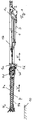
- FIG. 1 is a side view of a main boom 1 of a telescopic crane, not shown, shown.
- a base frame 2 of a superstructure is shown.
- On the base frame 2 of the main boom 1 is pivotally mounted with its main boom 1c in the usual manner about a substantially horizontal axis and a symbolically indicated by a line rocker cylinder 3, which engages the base frame and the main boom 1, in a corresponding manner set up and rocker ,
- the main boom 1 is shown in a so-called stowed position, in which the main boom 1 is aligned with its longitudinal direction substantially horizontally.
- the main boom 1 is designed as a telescopic boom with a base box 1 b and guided therein telescopic shots 1 d and has at its end remote from the base frame 2 of the superstructure end a main boom head 1 b and thus at the innermost telescopic section 1 d20.
- the telescopic boom can be extended and retracted in the usual way via a telescopic cylinder (not shown) arranged in the innermost telescopic section 1d.
- An extension of the main boom 1 in the form of a main boom extension 4 is detachably attached to the main boom head 1b.
- the main boom extension 4 can be used temporarily or permanently with the telescopic crane to achieve over the largest boom length of the main boom 1 beyond even greater overall length of the boom or to allow working behind building edges.
- This main boom extension 4 is designed as a lattice mast, which is a truss pipe construction in the usual way.
- the main boom 1 and the main boom extension 4 are located in the FIG. 1 in a 0 ° position or basic position in which the longitudinal direction H of the main boom 1 and the longitudinal direction V of the main boom extension 4 are aligned with one another or run parallel to one another.
- a so-called rocking angle a of the main boom 1 relative to the superstructure 2 is thus 0 ° in the stored position.
- the main boom extension 4 is spaced in this basic position of a bottom 10 and is thus supported by the main boom 1 via a bolt on the main boom head 1a.
- Such main boom extensions 4 are basically modular systems composed of individual main elements and can be assembled according to the requirements of its length or load capacity.
- the individual main elements have transportable dimensions and are not carried along with the telescopic crane in most cases, but are transported separately. If allow the axle loads of the telescopic crane and the size of the main boom extension 4, if necessary, the main boom extension 4 can be carried. This would then be in a transport position laterally next to and parallel to the main boom 1.
- the attachment to the main boom head 1a can be made elementary or as a preassembled unit or units.
- FIG. 2a shows a side view of an Abwinkellasche 9 in a fully extended 40 ° position.
- the sliding lug 9b is formed as an elongated flat profile with the stopper opening 9c and extends substantially parallel to the longitudinal direction V of the main boom extension 1.
- the sliding lug 9b has a bore 9j (see FIG Figure 2d ), via which the sliding tab 9b is detachably fastened in each case to a connecting bolt 9e on the main boom head 1a at one of the bolting points E and F.
- the connecting bolt 9e is aligned with its longitudinal extension parallel to the upper or lower roller head axles 12a, 12b.
- the guide plate 9d is pushed, which for this purpose has a closed rectangular cross-section with a guide opening 9f (see FIG. 2b ), in which the sliding tab 9b is inserted and slidably guided.
- the guide lug 9d per se is detachably fastened to the main boom extension 4 on one end facing the main jib head 1a via a respective further connecting bolt 9i in one of the bolting points G and H.
- the connecting pin 9i is aligned with its longitudinal extent parallel to the upper and lower roller head axles 12a, 12b.
- the terminal bolt 9i is through the stopper opening 9c of the sliding tab 9b passed.
- two stop holes 9g which are continuous and spaced apart in the longitudinal direction of the guide lug 9d, are provided (see FIG Figure 2d ) are arranged in the side parts of the guide tab 9d.
- a first of the two stop holes 9g serves to limit the angle of deflection b to 20 ° and a second to 40 °.
- the stop holes 9g for 40 ° are correspondingly closer to the main boom head 1a arranged to allow a larger displacement.
- a stop pin 9h is inserted into the respective stop hole, which then passes through the two opposite stop holes 9g and the intermediate stop opening 9c.
- the stopper pin 9h is inserted into the second of the two stopper holes 9g, which limits the angle of deflection b to 40 °.
- the stopper pin 9h is guided adjacent to the pin 9i in the stopper opening 9c.
- the bolt 9i would come into contact only with the opposing abutment surface 9a of the stopper opening 9c when no stopper bolt 9h is inserted.
- the second of the two stop holes 9g is free.
- FIG. 2b is a sectional view of FIG. 2a shown along the section line AA. It can be seen that the guide lug 9d has a rectangular cross-section with a central guide opening 9f, in which the sliding lug 9b is guided with its stop opening 9c.
- FIG. 2c a plan view of an Abwinkellasche 9 shown in a transport position.
- the Abwinkellasche 9 is not attached via the connecting bolt 9e on the main boom head 1a and the sliding tab 9b is inserted in the direction of the main boom extension 4 in the guide tab 9d.
- the connecting bolt 9e and the stopper pin 9h are inserted for storage.
- FIG. 2d shows a sectional view of Figure 2c along the section line BB in Figure 2c , In this view, the stop opening 12c and the two stop holes are clearly visible.
- FIG. 2e is a side view of an Abwinkellasche 9 shown in the Essentially the in FIG. 2a shown Abwinkellasche 9 corresponds. Unlike in the FIG. 2a the Abwinkellasche 9 is not shown in the 40 ° position, but in the 20 ° position. Correspondingly, the stopper bolt 9h is inserted in the stopper hole 9g remote from the main boom head 1a.
- FIG. 3 the main boom 1 after FIG. 1 with the main boom extension 4 in a 20 ° position, the previously described position is shown, in which the lowered tip 4a is supported on the floor 10.
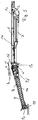
- FIG. 4 shows the main boom 1 after FIG. 3 with the main boom extension 1a in a 40 ° position, in which the lowered tip 4a is supported on the floor 10.
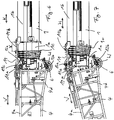
- FIG. 5 shows a detail view of FIG. 4 from the area of the coupling of the main boom extension 4 to the main boom 1 with a Abwinkellasche 9 in stop position to a desired maximum Abwinkel thoroughly.
- FIG. 6 a detail view from the field of coupling of the main boom extension 4 to the main boom 1 in the basic position.
- the kinetic energy for bending the main boom extension 4 is provided here as an alternative to the previously described embodiment via a combination of a coupling rod 11 with a telescoping cylinder telescopic main boom 1 available.
- the coupling rod 11 is aligned substantially parallel to the longitudinal direction H of the main boom 1 and to the longitudinal direction V of the main boom extension 4 and coupled to a first coupling rod end 11a in the region of the upper chord 4a of the main boom extension 4 via a horizontally extending pin.
- the opposite second coupling rod end 11 b is also mounted via a horizontally extending bolt on a base box 1 b of the main boom 1.
- the length of the coupling rod 11 is selected such that a telescopic weft 1c extended by an extension path x relative to the base box 1b is subsequently retractable and extendable in such a way that the main boom extension 4 can be lifted and lowered pivotally about the rocking axis W against the force of gravity of the main boom extension 4.
- the Coupling rod 11 are provided with a slot 11c to connect after extension of the main boom 1 to the extension x the coupling rod 11 easier with the main boom 1 and the main boom extension 4. A first slight lifting of the main boom extension 4 is required to relieve the upper bolt 6 and then remove.
- the telescopic section 1c is retracted and, viewed in relative terms, the length of the coupling rod 11 is released, which leads to angling of the main boom extension 4.
- the coupling rod 11 is removed.
- the main boom extension 4 further angled and the tip 4c of the main boom extension 4 slides through the floor 10 in the direction of the upper carriage 2.
- FIG. 7 is a view like in FIG. 6 shown in another position of the main boom extension 4. It can be seen that the main boom extension 4 is already bent so far that the tip 4 c has reached the bottom 10. The telescopic section 1c is retracted and the coupling rod 11 is relieved. When this position is reached, the next step is the removal of the coupling rod 11 and the further bending over the interaction of setting up the main boom 1 and the Abwinkellaschen. 9
- a backward angle of the main boom extension 4 takes place in the reverse order.
- main boom 1 may also be a lattice boom or a combination of telescopic boom, lattice boom and / or box boom.
- skin extension boom 4 lattice boom or box boom or combinations thereof are conceivable.
Landscapes
- Engineering & Computer Science (AREA)
- Mechanical Engineering (AREA)
- Jib Cranes (AREA)
Description
Die Erfindung betrifft einen Mobilkran mit einem wippbar hieran gelagerten und über einen Wippzylinder aufrichtbaren Hauptausleger und mit einer lösbar an einem Hauptauslegerkopf des Hauptauslegers über obere Bolzen und untere Bolzen verbundenen Hauptauslegerverlängerung, die Hauptauslegerverlängerung ausgehend von einer Grundstellung nach einem Lösen der oberen Bolzen mittels eines Abwinkelantriebs um eine Wippachse relativ zu dem Hauptausleger abwinkelbar ist, der Abwinkelantrieb an einem Fuß der Hauptauslegerverlängerung angreift, wobei ein für eine andere Aufgabe vorgesehener Antrieb des Mobilkrans die Bewegungsenergie für den Abwinkelantrieb liefert.The invention relates to a mobile crane with a rocker mounted thereon and erectable via a luffing jib main boom and with a detachably connected to a main boom head of the main boom on top bolts and lower bolts main boom extension, the main boom extension, starting from a normal position after loosening the upper bolt by means of a Abwinkelantriebs order a luffing axis is bendable relative to the main boom, the Abwinkelantrieb acts on a foot of the main boom extension, a provided for another task drive the mobile crane provides the kinetic energy for the Abwinkelantrieb.
Auch betrifft die Erfindung ein Verfahren zum Abwinkeln einer Hauptauslegerverlängerung relativ zu einem Hauptausleger eines Mobilkrans, wobei der Hauptausleger wippbar an dem Mobilkran gelagert und über einen Wippzylinder aufrichtbar ist, die Hauptauslegerverlängerung lösbar an einem Hauptauslegerkopf des Hauptauslegers über obere Bolzen und untere Bolzen verbunden ist, ein Abwinkelantrieb an einem Fuß der Hauptauslegerverlängerung angreift, wobei mittels des Abwinkelantriebs, der für das Abwinkeln seine Bewegungsenergie von einem Antrieb des Mobilkrans bezieht, der sonst für eine andere Aufgabe des Mobilkrans vorgesehen ist, die Hauptauslegerverlängerung ausgehend von einer Grundstellung um eine Wippachse relativ zu dem Hauptausleger angehoben wird, soweit bis die oberen Bolzen entlastet werden, dann die oberen Bolzen entfernt werden.Also, the invention relates to a method for bending a main boom extension relative to a main boom of a mobile crane, wherein the main boom is tiltably mounted on the mobile crane and erectable via a luffing cylinder, the main boom extension is releasably connected to a main boom head of the main boom via upper bolts and lower bolts, a Abwinkelantrieb attacks on a foot of the main boom extension, wherein by means of the Abwinkelantriebs, which refers to the deflection of its kinetic energy from a drive of the mobile crane, which is otherwise provided for another task of the mobile crane, the main boom extension from a basic position about a rocking axis relative to the main boom is raised, as far as the upper bolts are relieved, then the upper bolts are removed.
Das japanische Gebrauchsmuster
Auch das Patent
Aus dem deutschen Gebrauchsmuster
Der Erfindung liegt die Aufgabe zu Grunde, einen Mobilkran und ein Verfahren zum Abwinkeln einer Hauptauslegerverlängerung relativ zu einem Hauptausleger eines Mobilkrans zu schaffen, mit denen das Abwinkeln der Hauptauslegerverlängerung vereinfacht wird.The invention has for its object to provide a mobile crane and a method for bending a main boom extension relative to a main boom of a mobile crane, with which the bending of the main boom extension is simplified.
Diese Aufgabe wird durch einen Mobilkran mit den Merkmalen des Anspruchs 1 und durch ein Verfahren zum Abwinkeln einer Hauptauslegerverlängerung relativ zu einem Hauptausleger eines Mobilkrans mit den Merkmalen des Anspruchs 6 gelöst. Vorteilhafte Ausgestaltungen der Erfindung sind in den Unteransprüchen 2 bis 5 angegeben.This object is achieved by a mobile crane with the features of
Erfindungsgemäß wird bei einem Mobilkran mit einem wippbar hieran gelagerten und über einen Wippzylinder aufrichtbaren Hauptausleger und mit einer lösbar an einem Hauptauslegerkopf des Hauptauslegers über obere Bolzen und untere Bolzen verbundenen Hauptauslegerverlängerung, wobei die Hauptauslegerverlängerung ausgehend von einer Grundstellung nach einem Lösen der oberen Bolzen mittels eines Abwinkelantriebs um eine Wippachse relativ zu dem Hauptausleger abwinkelbar ist, der Abwinkelantrieb an einem Fuß der Hauptauslegerverlängerung angreift, wobei ein für eine andere Aufgabe vorgesehener Antrieb des Mobilkrans die Bewegungsenergie für den Abwinkelantrieb liefert, eine Vereinfachung dadurch erreicht, dass der Abwinkelantrieb derart ausgebildet ist, dass ein Teleskopierzylinder über ein Ein- und Ausfahren des Hauptauslegers die Bewegungsenergie für den Abwinkelantrieb liefert. Hierdurch wird erreicht, dass das Abwinkeln nicht über äußere Hilfsmittel oder zusätzliche Hilfszylinder erfolgt, sondern am Mobilkran vorhandene Antriebe verwendet werden, die ohnehin vorhanden sind. Das Abwinkeln erfolgt nicht über zusätzlich vorzusehende Hydraulikzylinder. Das Abwinkeln an sich erfolgt weitestgehend am Boden beziehungsweise der Ablagestellung des Hauptauslegers, so dass es nicht erforderlich ist, weit oberhalb der Oberkante des Mobilkrans zu arbeiten. Die Erfindung erlaubt das Abwinkeln der Hauptauslegerverlängerung bei auf einem ebenen Boden stehendem Mobilkran mit horizontal ausgerichtetem Teleskopausleger. Für den letzten Teil des Aufwippens der Hauptauslegerverlängerung in eine 20°- beziehungsweise 40°-Stellung wird der Wippzylinder des Hauptauslegers zu Hilfe genommen.According to the invention in a mobile crane with a rockable mounted thereto and erectable via a luffing jib main boom and with a detachably connected to a main boom head of the main boom via upper bolts and lower bolts main boom extension, the main boom extension, starting from a normal position after loosening the upper bolt by means of a Abwinkelantriebs about a luffing axis relative to the main boom is angled, the Abwinkelantrieb attacks on a foot of the main boom extension, a provided for another task drive the mobile crane provides the kinetic energy for the Abwinkelantrieb, a simplification achieved in that the Abwinkelantrieb is designed such that a Telescoping cylinder via a retraction and extension of the main boom provides the kinetic energy for the Abwinkelantrieb. This ensures that the bending is not done via external aids or additional auxiliary cylinder, but existing drives are used on the mobile crane, which are present anyway. The bending does not take place via additional hydraulic cylinder to be provided. The bending itself is largely at the bottom or the storage position of the main boom, so that it is not necessary to work well above the top of the mobile crane. The invention allows the bending of the main boom extension with standing on a flat ground mobile crane with horizontally aligned telescopic boom. For the last part of the raising of the main boom extension into a 20 ° or 40 ° position, the luffing cylinder of the main boom is used.
Hierbei ist vorgesehen, dass insbesondere der Abwinkelantrieb einerseits an dem Hauptausleger und andererseits an der Hauptauslegerverlängerung im Bereich ihres Obergurtes angreift. Außerdem ist vorteilhafterweise der Abwinkelantrieb derart ausgebildet, dass die Hauptauslegerverlängerung entgegen der Schwerkraftwirkung der Hauptauslegerverlängerung um die Wippachse schwenkend anhebbar und absenkbar ist. Hierbei ist insbesondere die Wippachse von einer unteren Rollenkopfachse gebildet.It is provided that in particular the Abwinkelantrieb engages on the one hand on the main boom and on the other hand on the main boom extension in the region of the upper flange. In addition, advantageously, the Abwinkelantrieb is designed such that the main boom extension against the gravitational force of the main boom extension to the rocking axis is pivotally raised and lowered. In this case, in particular, the rocking axis is formed by a lower roller head axis.
In einer vorteilhaften Variante ist vorgesehen, dass der Abwinkelantrieb eine Koppelstange umfasst, die Koppelstange an einem ersten Koppelstangenende an dem Obergurt der Hauptauslegerverlängerung befestigt ist und an einem zweiten Koppelstangenende an dem Hauptausleger befestigt ist, die Länge der Koppelstange so gewählt ist, dass ein zuvor um einen Ausfahrweg ausgefahrener Hauptausleger anschließend derart ein- und ausfahrbar ist, dass die Hauptauslegerverlängerung entgegen der Schwerkraftwirkung der Hauptauslegerverlängerung um die Wippachse schwenkend anhebbar und absenkbar ist.In an advantageous variant it is provided that the Abwinkelantrieb comprises a coupling rod, the coupling rod is attached to a first coupling rod end to the upper flange of the main boom extension and attached to a second coupling rod end to the main boom, the length of the coupling rod is selected so that a previously order a Ausfahrweg extended main boom is then so retractable and extendable that the main boom extension against the gravitational force of the main boom extension is pivotally raised and lowered about the rocker axis.
Erfindungsgemäß wird bei einem Verfahren zum Abwinkeln einer Hauptauslegerverlängerung relativ zu einem Hauptausleger eines Mobilkrans, wobei der Hauptausleger wippbar an dem Mobilkran gelagert und über einen Wippzylinder aufrichtbar ist, die Hauptauslegerverlängerung lösbar an einem Hauptauslegerkopf des Hauptauslegers über obere Bolzen und untere Bolzen verbunden ist, ein Abwinkelantrieb an einem Fuß der Hauptauslegerverlängerung angreift, wobei mittels des Abwinkelantriebs, der für das Abwinkeln seine Bewegungsenergie von einem Antrieb des Mobilkrans bezieht, der sonst für eine andere Aufgabe des Mobilkrans vorgesehen ist, die Hauptauslegerverlängerung ausgehend von einer Grundstellung um eine Wippachse relativ zu dem Hauptausleger angehoben wird, soweit bis die oberen Bolzen entlastet werden, dann die oberen Bolzen entfernt werden, eine Vereinfachung dadurch erreicht, dass zwischen dem Hauptauslegerkopf und einem Obergurt der Hauptauslegerverlängerung Abwinkellaschen eingesetzt werden beziehungsweise eingesetzt sind, über die eine gewünschte Abwinkelung der Hauptauslegerverlängerung zu dem Hauptausleger begrenzt ist, mittels des Abwinkelantriebs die Hauptauslegerverlängerung abgesenkt wird, solange bis die maximale Abwinkelstellung erreicht wird oder eine Spitze der Hauptauslegerverlängerung auf einem Boden zur Auflage kommt, der Antrieb des Mobilkrans von dem Abwinkelantrieb getrennt wird und wenn die maximale Abwinkelstellung noch nicht erreicht ist, mittels Aufrichten des Hauptauslegers die Hauptauslegerverlängerung bis zum Erreichen der gewünschten Abwinkelung abgewinkelt wird und zur Bereitstellung der Bewegungsenergie eine Koppelstange mit dem Hauptausleger und der Hauptauslegerverlängerung verbunden wird und über ein Ein- und Ausfahren des Hauptauslegers die Bewegungsenergie bereitgestellt wird. In Bezug auf die hiermit verbundenen Vorteile wird auf die Ausführungen zuvor für den Mobilkran verwiesen.According to the invention, in a method for bending a main boom extension relative to a main boom of a mobile crane, wherein the main boom is tiltably mounted on the mobile crane and erectable via a luffing cylinder, the main boom extension is releasably connected to a main boom head of the main boom via upper bolts and lower bolts, an angled drive engages a foot of the main boom extension, wherein by means of the Abwinkelantriebs, which draws its kinetic energy from a drive of the mobile crane, which is otherwise provided for another task of the mobile crane, raised the main boom extension from a basic position about a rocking axis relative to the main boom is, as far as the upper bolts are relieved, then the upper bolts are removed, a simplification achieved in that between the main boom head and a top flange of the main boom extension Abwinkellaschen e are set or are used, via which a desired bending of the main boom extension is limited to the main boom, the main boom extension is lowered by means of the Abwinkelantriebs until the maximum Abwinkelstellung is reached or a tip of the main boom extension on a floor for support, the drive of the mobile crane is separated from the Abwinkelantrieb and if the maximum Abwinkelstellung has not been reached by raising the main boom, the main boom extension is bent until reaching the desired angle and to provide the kinetic energy coupling rod is connected to the main boom and the main boom extension and a on and Extending the main boom the kinetic energy is provided. With regard to the advantages associated with this, the comments made previously for the Mobile crane referenced.
Im Zusammenhang mit der vorliegenden Erfindung wird unter einem Mobilkran sowohl ein verfahrbarer Teleskopkran als auch ein verfahrbarer Raupenkran mit Gittermastausleger verstanden.In the context of the present invention, a mobile crane is understood as meaning both a mobile telescopic crane and a movable crawler crane with a lattice boom.
Nachfolgend wird die Erfindung an Hand eines in einer Zeichnung dargestellten Ausführungsbeispiels näher erläutert. Es zeigen:
-
Figur 1 -
Figur 2a eine Seitenansicht einer Abwinkellasche in einer 40°-Stellung, -
Figur 2b eine Schnittansicht vonFigur 2a , -
Figur 2c eine Draufsicht einer Abwinkellasche in einer Transport-Stellung, -
Figur 2d eine Schnittansicht vonFigur 2c , -
Figur 2e eine Seitenansicht einer Abwinkellasche in einer 20°-Stellung, -
Figur 3Figur 1 -
Figur 4Figur 1 -
Figur 5 eine Detailansicht vonFigur 4 -
Figur 6 -
Figur 7 eine Ansicht wie inFigur 6
-
FIG. 1 a side view of a main boom with a main boom extension in a basic position, -
FIG. 2a a side view of a Abwinkellasche in a 40 ° position, -
FIG. 2b a sectional view ofFIG. 2a . -
Figure 2c a plan view of a Abwinkellasche in a transport position, -
Figure 2d a sectional view ofFigure 2c . -
FIG. 2e a side view of a Abwinkellasche in a 20 ° position, -
FIG. 3 after the main boomFIG. 1 with the main boom extension in a 20 ° position, -
FIG. 4 after the main boomFIG. 1 with the main boom extension in a 40 ° position, -
FIG. 5 a detailed view ofFIG. 4 with an Abwinkellasche in stop position, -
FIG. 6 a detailed view of the area of the coupling of the main boom extension to the main boom and a coupling rod for bending and -
FIG. 7 a view like inFIG. 6 in another position the Main boom extension.
In der
Derartige Hauptauslegerverlängerungen 4 sind grundsätzlich als Baukastensysteme aus einzelnen Hauptelementen aufgebaut und können je nach Erfordernis an dessen Länge beziehungsweise Tragkraft zusammengestellt werden. Die einzelnen Hauptelemente weisen transportfähige Abmessungen auf und werden in den meisten Fällen nicht mit dem Teleskopkran mitgeführt, sondern werden separat transportiert. Wenn es die Achslasten des Teleskopkrans und die Baugröße der Hauptauslegerverlängerung 4 zulassen, kann bei Bedarf die Hauptauslegerverlängerung 4 mitgeführt werden. Diese würde sich dann in einer Transportstellung seitlich neben und parallel zu dem Hauptausleger 1 befinden. Eine Verbindung der einzelnen Hauptelemente aneinander zu der gewünschten Hauptauslegerverlängerung 4 erfolgt über Bolzenverbindungen in entsprechenden Verbolzungsstellen A, B, C und D. Der Anbau an den Hauptauslegerkopf 1a kann hauptelementweise oder als vormontierte Einheit beziehungsweise Einheiten erfolgen.Such
Die
In der
Des Weiteren ist in der
Die
In der
In der
Die
Die
In der
In der
Ein Zurückwinkeln der Hauptauslegerverlängerung 4 erfolgt in umgekehrter Reihenfolge.A backward angle of the
Obwohl im Zusammenhang mit dem vorliegenden Ausführungsbeispiel der Hauptausleger 1 als Teleskopausleger und die Hautauslegerverlängerung 4 als Gittermastausleger beschrieben sind, ist die Erfindung auch auf andere Ausgestaltungen von Hauptausleger 1 und Hautauslegerverlängerung 4 anwendbar. Der Hauptausleger 1 kann auch ein Gittermastausleger oder eine Kombination von Teleskopausleger, Gittermastausleger und/oder Kastenausleger sein. Für die Hautauslegerverlängerung 4 sind Gittermastausleger oder Kastenausleger oder Kombinationen hiervon denkbar.Although in the context of the present embodiment of the
- 1 Hauptausleger1 main boom
- 1a Hauptauslegerkopf1a main boom head
- 1b Grundkasten1b basic box
- 1c Hauptauslegerfuß1c main jib foot
- 1d Teleskopschuss1d telescopic shot
- 2 Grundrahmen2 basic frames
- 3 Wippzylinder3 rocker cylinders
- 4 Hauptauslegerverlängerung4 main boom extension
- 4a Obergurt4a upper strap
- 4b Untergurt4b bottom strap
- 4c Spitze4c tip
- 4d Fuß4d foot
- 5 oberer Bolzen5 upper bolt
- 6 unterer Bolzen6 lower bolt
- 7 Zugstange7 drawbar
- 8 Verbolzungsstelle8 bolting point
- 9 Abwinkellasche9 Abwinkellasche
- 9a Anschlagfläche9a stop surface
- 9b Schiebelasche9b sliding latch
- 9c Anschlagsöffnung9c stop opening
- 9d Führungslasche9d guide strap
- 9e Anschlussbolzen9e connecting bolts
- 9f Führungsöffnung9f guide opening
- 9g Anschlagsbohrung9g stop hole
- 9h Anschlagbolzen9h stop bolt
- 9i Anschlussbolzen9i connecting bolts
- 9j Bohrung9j bore
- 10 Boden10 floor
- 11 Koppelstange11 coupling rod
- 11a erstes Koppelstangenende11a first coupling rod end
- 11b zweites Koppelstangenende11b second coupling rod end
- 11c Langloch11c long hole
- 12a obere Rollenkopfachse12a upper roller head axle
- 12b untere Rollenkopfachse12b lower roller head axle
- A VerbolzungsstelleA bolting point
- B VerbolzungsstelleB bolting point
- C VerbolzungsstelleC bolting point
- D VerbolzungsstelleD bolting point
- E VerbolzungsstelleE bolting point
- F VerbolzungsstelleF bolting point
- G VerbolzungsstelleG Verbolzungsstelle
- H VerbolzungsstelleH bolting point
- a Wippwinkela rocking angle
- b Abwinkelwinkelb angle of attack
- c Längsrichtungc longitudinal direction
- x Ausfahrwegx extension path
- H Längsrichtung des HauptauslegersH longitudinal direction of the main boom
- V Längsrichtung der HauptauslegerverlängerungV Lengthwise direction of main boom extension
- W WippachseW rocking axis
Claims (6)
- Mobile crane with a main jib (1) luffably mounted thereon and able to be raised via a luffing cylinder (3), and with a main jib extension (4) releasably connected to a main jib head (1a) of the main jib (1) via upper bolts (5) and lower bolts (6), wherein the main jib extension (4), starting from a basic position after release of the upper bolts (5), is able to be angled about a luffing axis (W) relative to the main jib (1) by means of an angling drive, the angling drive engages on a foot (4d) of the main jib extension (4), wherein a drive of the mobile crane, which is provided for another task, provides the movement energy for the angling drive, characterised in that the angling drive is designed such that the movement energy for the angling drive is provided by retracting and extending the main jib (1) by means of a telescopic cylinder of the main jib (1).
- Mobile crane as claimed in claim 1, characterised in that the angling drive engages the main jib (1) on the one hand and engages the main jib extension (4) in the region of its top chord (4a) on the other hand.
- Mobile crane as claimed in claim 1 or 2, characterised in that the angling drive is designed in such a way that the main jib extension (4) can be raised and lowered so as to pivot about the luffing axis (W) against the effect of the gravitational force of the main jib extension (4).
- Mobile crane as claimed in any one of claims 1 to 3, characterised in that the luffing axis (W) is formed by a lower rolling head spindle (12b).
- Mobile crane as claimed in any one of claims 1 to 4, characterised in that the angling drive comprises a coupling rod (11), the coupling rod (11) is fastened at a first coupling rod end (11a) to the top chord (4a) of the main jib extension (4) and is fastened at a second coupling rod end (11b) to the main jib (1), the length of the coupling rod (11) is selected such that a main jib (1) previously extended by the distance of an extension path (x) can subsequently be retracted and extended such that the main jib extension (4) can be raised and lowered so as to pivot about the luffing axis (W) against the effect of the gravitational force of the main jib extension (4).
- Method for angling a main jib extension (4) relative to a main jib (1) of a mobile crane, in particular a mobile crane as claimed in any one of claims 1 to 5, wherein the main jib (1) is luffably mounted on the mobile crane and can be raised via a luffing cylinder (3), the main jib extension (4) is releasably connected to a main jib head (1a) of the main jib (1) via upper bolts (5) and lower bolts (6), an angling drive engages on a foot (4d) of the main jib extension (4), wherein by means of the angling drive which, for the angling procedure, draws its movement energy from a drive of the mobile crane which is otherwise provided for another task of the mobile crane, the main jib extension (4), starting from a basic position, is raised about a luffing axis (W) relative to the main jib (1) until the upper bolts (5) are relieved, then the upper bolts (5) are removed, characterised in that angling plates (9) are inserted, or have been inserted, between the main jib head (1a) and a top chord (4a) of the main jib extension (4), by means of which angling plates desired angling of the main jib extension (4) with respect the main jib (1) is limited, the main jib extension (4) is lowered by means of the angling drive for as long as until the maximum angling position is reached or a tip (4c) of the main jib extension (4) comes to rest on a ground (10), the drive of the mobile crane is disconnected from the angling drive and if the maximum angling position is not yet reached, the main jib (1) is raised in order to angle the main jib extension (4) until the desired angling is achieved and in order to provide the movement energy a coupling rod (11) is connected to the main jib (1) and the main jib extension (4) and the movement energy is provided by retracting and extending the main jib (1).
Applications Claiming Priority (2)
| Application Number | Priority Date | Filing Date | Title |
|---|---|---|---|
| DE102015120350.2A DE102015120350B3 (en) | 2015-11-24 | 2015-11-24 | Mobile crane for bending a main boom extension relative to a main boom of a mobile crane |
| PCT/EP2016/078467 WO2017089356A1 (en) | 2015-11-24 | 2016-11-22 | Mobile crane and method for angling a main boom extension in relation to a main boom of a mobile crane |
Publications (2)
| Publication Number | Publication Date |
|---|---|
| EP3337752A1 EP3337752A1 (en) | 2018-06-27 |
| EP3337752B1 true EP3337752B1 (en) | 2019-05-08 |
Family
ID=57354395
Family Applications (2)
| Application Number | Title | Priority Date | Filing Date |
|---|---|---|---|
| EP16798537.3A Active EP3347300B1 (en) | 2015-11-24 | 2016-11-22 | Mobile crane for angling a main jib extension relative to a main jib of a mobile crane |
| EP16798539.9A Active EP3337752B1 (en) | 2015-11-24 | 2016-11-22 | Mobile crane and method for angling a main boom extension in relation to a main boom of a mobile crane |
Family Applications Before (1)
| Application Number | Title | Priority Date | Filing Date |
|---|---|---|---|
| EP16798537.3A Active EP3347300B1 (en) | 2015-11-24 | 2016-11-22 | Mobile crane for angling a main jib extension relative to a main jib of a mobile crane |
Country Status (5)
| Country | Link |
|---|---|
| US (2) | US10640340B2 (en) |
| EP (2) | EP3347300B1 (en) |
| CN (2) | CN108290724B (en) |
| DE (1) | DE102015120350B3 (en) |
| WO (2) | WO2017089356A1 (en) |
Families Citing this family (12)
| Publication number | Priority date | Publication date | Assignee | Title |
|---|---|---|---|---|
| JP6531448B2 (en) * | 2015-03-20 | 2019-06-19 | 株式会社タダノ | Jib connection structure |
| DE102015119379B3 (en) | 2015-11-10 | 2017-03-30 | Terex Global Gmbh | Mobile crane and method for bending a main boom extension relative to a main boom of a mobile crane |
| DE102015119381B3 (en) | 2015-11-10 | 2017-04-27 | Terex Global Gmbh | Mobile crane and method for bending a main boom extension relative to a main boom of a mobile crane |
| DE102015120350B3 (en) | 2015-11-24 | 2017-05-24 | Terex Global Gmbh | Mobile crane for bending a main boom extension relative to a main boom of a mobile crane |
| DE102016114837A1 (en) | 2016-08-10 | 2018-02-15 | Terex Global Gmbh | Telescopic boom with guy system for a mobile crane and guying system |
| DE102017101113B3 (en) | 2017-01-20 | 2018-07-12 | Terex Global Gmbh | Telescopic boom with pole tensioning system for a mobile crane and guying method |
| DE102017110412B4 (en) * | 2017-05-12 | 2020-06-10 | Liebherr-Werk Ehingen Gmbh | Telescopic boom and mobile crane |
| DE102019104142B9 (en) * | 2019-02-19 | 2020-11-19 | Liebherr-Werk Ehingen Gmbh | Foldable suspended ballast guide for a crane |
| DE102020101101B3 (en) | 2020-01-17 | 2021-05-20 | Tadano Demag Gmbh | Boom system for a vehicle crane with anchoring device as well as a method for upgrading and dismantling an anchoring device of a vehicle crane |
| CN112141912B (en) * | 2020-09-02 | 2022-01-07 | 中联重科股份有限公司 | Pull plate assembly, crane boom and crane |
| JP2022084003A (en) | 2020-11-25 | 2022-06-06 | タダノ デマグ ゲーエムベーハー | Telescopic jib system of mobile crane with basic telescopic jib and additional telescopic jib and corresponding method |
| CN113753772B (en) * | 2021-08-31 | 2023-06-20 | 湖南三一中型起重机械有限公司 | Pin inserting and pulling mechanism and crane |
Family Cites Families (40)
| Publication number | Priority date | Publication date | Assignee | Title |
|---|---|---|---|---|
| DE291531C (en) | ||||
| US3085695A (en) * | 1961-03-23 | 1963-04-16 | Carl A Miller | Hinge for crane boom |
| FR2075866A1 (en) | 1969-12-31 | 1971-10-15 | Inst Foerdertechnik | |
| GB1470488A (en) | 1975-05-21 | 1977-04-14 | Hiab Foco Ab | Crane adapted to be mounted on a vehicle |
| FR2409225A1 (en) * | 1977-11-21 | 1979-06-15 | Creusot Loire | IMPROVEMENT WITH TELESCOPIC CRANES |
| US4318488A (en) | 1980-07-28 | 1982-03-09 | Harnischfeger Corporation | Method of extending a jib of a telescopic crane |
| US4394941A (en) | 1981-08-31 | 1983-07-26 | Thomas L. Shannon, Jr. | Fluid dispenser |
| JPS60100390A (en) * | 1983-11-04 | 1985-06-04 | 株式会社デンソー | Supporting structure of ceramic heater |
| JPS60100390U (en) | 1983-12-14 | 1985-07-09 | 株式会社 多田野鉄工所 | Variable tilt device for auxiliary jib in hydraulic telescopic boom with auxiliary jib |
| US4653655A (en) * | 1985-12-23 | 1987-03-31 | Harnischfeger Corporation | Crane boom having variable angle offset capability |
| JPS6327396A (en) | 1986-07-21 | 1988-02-05 | 株式会社タダノ | Jib extended to expansion boom |
| DD291531A5 (en) * | 1990-01-08 | 1991-07-04 | Maschinenbau "Karl Marx",De | BOOMS WITH ONE DEVICE FOR ONE OR MULTIPLE TIPPABLE BOOM EXTENSIONS FOR CRANES, ESPECIALLY MOBILE CRANES |
| FR2719574B1 (en) | 1994-05-06 | 1996-07-26 | Ppm | Extension set for telescopic boom of mobile crane and mobile crane when applying. |
| FR2732000B1 (en) * | 1995-03-22 | 1997-05-30 | Potain Sa | AUTOMATED MOUNT CRANE WITH FOLDABLE BOOM ON ITSELF |
| JPH09104588A (en) | 1995-10-06 | 1997-04-22 | Komatsu Ltd | Auxiliary jib protrusion and storage device for crane |
| CA2198953C (en) * | 1996-03-04 | 2000-10-10 | Michael J. Wanek | Offsetting link assembly for folding luffing jib |
| CN2364010Y (en) | 1999-03-26 | 2000-02-16 | 郑州铁路局工务机械厂 | Hydraulic arm-folding crane |
| BE1012862A5 (en) | 1999-08-31 | 2001-04-03 | Lille Allebroer Leo Alix De | Equipment for moving loads, making use of a mobile platform |
| DE10321493B4 (en) * | 2003-05-13 | 2006-07-20 | Grove U.S. Llc | Folding pinnacle bending |
| JP2007503369A (en) * | 2003-08-22 | 2007-02-22 | テレックス−デマグ ゲーエムベーハー ウント コー.カーゲー | Mobile crane boom with self-sufficient hydraulic unit |
| US7546928B2 (en) * | 2006-10-27 | 2009-06-16 | Manitowoc Crane Companies, Inc. | Mobile lift crane with variable position counterweight |
| EP2137093B1 (en) | 2007-04-19 | 2016-09-28 | Terex Cranes Germany GmbH | Method for installing an auxiliary boom to a main boom on a mobile crane |
| DE202007012204U1 (en) * | 2007-08-29 | 2007-10-31 | Terex-Demag Gmbh & Co. Kg | Element for connecting a grid system |
| CN101628691A (en) | 2008-07-18 | 2010-01-20 | 卫华集团有限公司 | Pitch winding mechanism of crane |
| DE102009007776A1 (en) | 2009-02-04 | 2010-08-12 | Terex Demag Gmbh | Control for an adjustable boom extension of a mobile crane |
| DE102009010452A1 (en) * | 2009-02-26 | 2010-09-02 | Terex-Demag Gmbh | Method and device for mounting and dismounting an attachment on the main boom of a mobile crane |
| DE102009022262A1 (en) | 2009-05-22 | 2010-11-25 | Terex Demag Gmbh | Angular adjustment of a boom system |
| CN201458603U (en) | 2009-08-12 | 2010-05-12 | 中国船舶重工集团公司第七一三研究所 | Folding mechanism of lifting arm |
| DE102009053235A1 (en) | 2009-11-06 | 2011-05-19 | Gottwald Port Technology Gmbh | Handling system for ISO containers with a container bridge |
| DE102010007545A1 (en) | 2010-02-11 | 2011-08-11 | Gottwald Port Technology GmbH, 40597 | Crane, especially mobile harbor crane, with a hybrid propulsion system |
| DE102011053014A1 (en) | 2011-08-26 | 2013-02-28 | Demag Cranes & Components Gmbh | Control arrangement for the parallel operation of at least two hoists, in particular cranes |
| CN102602825B (en) | 2012-03-13 | 2014-07-16 | 中联重科股份有限公司 | Auxiliary arm unfolding and folding device, arm support structure and crane |
| CN103359636A (en) * | 2012-03-28 | 2013-10-23 | 江苏华澄重工有限公司 | Boom gravity center compensation device for single-boom portal crane |
| DE102012023814B4 (en) | 2012-12-05 | 2015-02-05 | Liebherr-Werk Ehingen Gmbh | Folding tip for a mobile crane and method for pivoting the folding top |
| DE102014102121A1 (en) | 2014-02-19 | 2015-08-20 | Terex Mhps Gmbh | Hafenkran |
| DE102014003831A1 (en) | 2014-03-18 | 2015-09-24 | Liebherr-Werk Ehingen Gmbh | Crane boom system with a first boom element and a second cantilever element hinged thereto and tiltable crane |
| DE102015202734A1 (en) | 2015-02-16 | 2016-08-18 | Terex Cranes Germany Gmbh | Crane and method for influencing a deformation of a boom system of such a crane |
| DE102015119379B3 (en) | 2015-11-10 | 2017-03-30 | Terex Global Gmbh | Mobile crane and method for bending a main boom extension relative to a main boom of a mobile crane |
| DE102015119381B3 (en) | 2015-11-10 | 2017-04-27 | Terex Global Gmbh | Mobile crane and method for bending a main boom extension relative to a main boom of a mobile crane |
| DE102015120350B3 (en) | 2015-11-24 | 2017-05-24 | Terex Global Gmbh | Mobile crane for bending a main boom extension relative to a main boom of a mobile crane |
-
2015
- 2015-11-24 DE DE102015120350.2A patent/DE102015120350B3/en not_active Expired - Fee Related
-
2016
- 2016-11-22 CN CN201680068460.5A patent/CN108290724B/en active Active
- 2016-11-22 CN CN201680068448.4A patent/CN108883916B/en not_active Expired - Fee Related
- 2016-11-22 EP EP16798537.3A patent/EP3347300B1/en active Active
- 2016-11-22 US US15/778,432 patent/US10640340B2/en active Active
- 2016-11-22 EP EP16798539.9A patent/EP3337752B1/en active Active
- 2016-11-22 WO PCT/EP2016/078467 patent/WO2017089356A1/en active Application Filing
- 2016-11-22 US US15/778,124 patent/US10781083B2/en active Active
- 2016-11-22 WO PCT/EP2016/078461 patent/WO2017089353A1/en active Application Filing
Non-Patent Citations (1)
| Title |
|---|
| None * |
Also Published As
| Publication number | Publication date |
|---|---|
| US10781083B2 (en) | 2020-09-22 |
| CN108883916B (en) | 2020-01-03 |
| US20180346292A1 (en) | 2018-12-06 |
| DE102015120350B3 (en) | 2017-05-24 |
| WO2017089353A1 (en) | 2017-06-01 |
| CN108290724B (en) | 2019-09-27 |
| EP3337752A1 (en) | 2018-06-27 |
| US10640340B2 (en) | 2020-05-05 |
| US20180339889A1 (en) | 2018-11-29 |
| WO2017089356A1 (en) | 2017-06-01 |
| EP3347300A1 (en) | 2018-07-18 |
| CN108883916A (en) | 2018-11-23 |
| EP3347300B1 (en) | 2019-05-08 |
| CN108290724A (en) | 2018-07-17 |
Similar Documents
| Publication | Publication Date | Title |
|---|---|---|
| EP3337752B1 (en) | Mobile crane and method for angling a main boom extension in relation to a main boom of a mobile crane | |
| EP3356281B1 (en) | Mobile crane and method for angling a main jib extension relative to a main jib of a mobile crane | |
| DE102015119379B3 (en) | Mobile crane and method for bending a main boom extension relative to a main boom of a mobile crane | |
| EP2465809B1 (en) | Telescopic system for crane boom and jib | |
| DE102011115355A1 (en) | Boom element for telescopic boom, particularly telescopic shot or telescopic boom base section for construction vehicle, particularly mobile crane, comprises bowl-shaped corner posts and lattice bars | |
| DE102007058553A1 (en) | Lateral bracing for a lattice boom of a crane | |
| DE202008006457U1 (en) | Boom element for a hoist | |
| DE102014012661B4 (en) | Method of operating a crane and crane | |
| EP2288770A2 (en) | Device for demolishing constructions | |
| DE102015006117A1 (en) | Method of operating a crane and crane | |
| DE102013011173B4 (en) | Method for assembling a crane as well as articulation, telescopic boom and crane | |
| DE102015001619B4 (en) | Boom system for a mobile crane as well as a mobile crane | |
| DE202016005419U1 (en) | Crane and counterweight for a crane | |
| DE102017000389B4 (en) | Crane boom, crane with such a crane boom and method for attaching a guy support to such a crane boom | |
| DE102013006259B4 (en) | Telescopic boom and crane | |
| DE102013011180B4 (en) | Collar storage for a telescopic boom as well as telescopic boom and crane | |
| DE69810981T2 (en) | Technique for erecting the mast for a telescopic crane | |
| DE102021130736B4 (en) | Telescopic boom system of a mobile crane with a basic telescopic boom and an additional telescopic boom and method therefor | |
| DE102020131617B4 (en) | Mobile crane comprising an upper carriage with at least one bearing point for bolting on a boom | |
| EP4083346B1 (en) | Supporting device for an automatic concrete pump | |
| DE202017000243U1 (en) | Boom adjustment device for a working device | |
| DE10226319B4 (en) | Mobile crane with retractable and extendable coupling device for a counterweight | |
| DE102022128653A1 (en) | Mobile crane with lattice boom, lattice boom and method for assembling such a crane | |
| DE2335407C3 (en) | Load carrying device, in particular on the boom of a crane or the like. hinged | |
| DE102015006115A1 (en) | Method of operating a crane and crane |
Legal Events
| Date | Code | Title | Description |
|---|---|---|---|
| STAA | Information on the status of an ep patent application or granted ep patent |
Free format text: STATUS: UNKNOWN |
|
| STAA | Information on the status of an ep patent application or granted ep patent |
Free format text: STATUS: THE INTERNATIONAL PUBLICATION HAS BEEN MADE |
|
| PUAI | Public reference made under article 153(3) epc to a published international application that has entered the european phase |
Free format text: ORIGINAL CODE: 0009012 |
|
| STAA | Information on the status of an ep patent application or granted ep patent |
Free format text: STATUS: REQUEST FOR EXAMINATION WAS MADE |
|
| 17P | Request for examination filed |
Effective date: 20180321 |
|
| AK | Designated contracting states |
Kind code of ref document: A1 Designated state(s): AL AT BE BG CH CY CZ DE DK EE ES FI FR GB GR HR HU IE IS IT LI LT LU LV MC MK MT NL NO PL PT RO RS SE SI SK SM TR |
|
| AX | Request for extension of the european patent |
Extension state: BA ME |
|
| GRAP | Despatch of communication of intention to grant a patent |
Free format text: ORIGINAL CODE: EPIDOSNIGR1 |
|
| STAA | Information on the status of an ep patent application or granted ep patent |
Free format text: STATUS: GRANT OF PATENT IS INTENDED |
|
| DAV | Request for validation of the european patent (deleted) | ||
| DAX | Request for extension of the european patent (deleted) | ||
| RIC1 | Information provided on ipc code assigned before grant |
Ipc: B66C 23/68 20060101AFI20190205BHEP Ipc: B66C 23/70 20060101ALI20190205BHEP Ipc: B66C 23/42 20060101ALI20190205BHEP |
|
| INTG | Intention to grant announced |
Effective date: 20190222 |
|
| RAP1 | Party data changed (applicant data changed or rights of an application transferred) |
Owner name: TEREX GLOBAL GMBH |
|
| GRAS | Grant fee paid |
Free format text: ORIGINAL CODE: EPIDOSNIGR3 |
|
| GRAA | (expected) grant |
Free format text: ORIGINAL CODE: 0009210 |
|
| STAA | Information on the status of an ep patent application or granted ep patent |
Free format text: STATUS: THE PATENT HAS BEEN GRANTED |
|
| AK | Designated contracting states |
Kind code of ref document: B1 Designated state(s): AL AT BE BG CH CY CZ DE DK EE ES FI FR GB GR HR HU IE IS IT LI LT LU LV MC MK MT NL NO PL PT RO RS SE SI SK SM TR |
|
| REG | Reference to a national code |
Ref country code: GB Ref legal event code: FG4D Free format text: NOT ENGLISH |
|
| REG | Reference to a national code |
Ref country code: CH Ref legal event code: EP Ref country code: AT Ref legal event code: REF Ref document number: 1129825 Country of ref document: AT Kind code of ref document: T Effective date: 20190515 |
|
| REG | Reference to a national code |
Ref country code: IE Ref legal event code: FG4D Free format text: LANGUAGE OF EP DOCUMENT: GERMAN |
|
| REG | Reference to a national code |
Ref country code: DE Ref legal event code: R096 Ref document number: 502016004644 Country of ref document: DE |
|
| REG | Reference to a national code |
Ref country code: NL Ref legal event code: MP Effective date: 20190508 |
|
| REG | Reference to a national code |
Ref country code: LT Ref legal event code: MG4D |
|
| PG25 | Lapsed in a contracting state [announced via postgrant information from national office to epo] |
Ref country code: NO Free format text: LAPSE BECAUSE OF FAILURE TO SUBMIT A TRANSLATION OF THE DESCRIPTION OR TO PAY THE FEE WITHIN THE PRESCRIBED TIME-LIMIT Effective date: 20190808 Ref country code: ES Free format text: LAPSE BECAUSE OF FAILURE TO SUBMIT A TRANSLATION OF THE DESCRIPTION OR TO PAY THE FEE WITHIN THE PRESCRIBED TIME-LIMIT Effective date: 20190508 Ref country code: LT Free format text: LAPSE BECAUSE OF FAILURE TO SUBMIT A TRANSLATION OF THE DESCRIPTION OR TO PAY THE FEE WITHIN THE PRESCRIBED TIME-LIMIT Effective date: 20190508 Ref country code: HR Free format text: LAPSE BECAUSE OF FAILURE TO SUBMIT A TRANSLATION OF THE DESCRIPTION OR TO PAY THE FEE WITHIN THE PRESCRIBED TIME-LIMIT Effective date: 20190508 Ref country code: NL Free format text: LAPSE BECAUSE OF FAILURE TO SUBMIT A TRANSLATION OF THE DESCRIPTION OR TO PAY THE FEE WITHIN THE PRESCRIBED TIME-LIMIT Effective date: 20190508 Ref country code: PT Free format text: LAPSE BECAUSE OF FAILURE TO SUBMIT A TRANSLATION OF THE DESCRIPTION OR TO PAY THE FEE WITHIN THE PRESCRIBED TIME-LIMIT Effective date: 20190908 Ref country code: SE Free format text: LAPSE BECAUSE OF FAILURE TO SUBMIT A TRANSLATION OF THE DESCRIPTION OR TO PAY THE FEE WITHIN THE PRESCRIBED TIME-LIMIT Effective date: 20190508 Ref country code: AL Free format text: LAPSE BECAUSE OF FAILURE TO SUBMIT A TRANSLATION OF THE DESCRIPTION OR TO PAY THE FEE WITHIN THE PRESCRIBED TIME-LIMIT Effective date: 20190508 Ref country code: FI Free format text: LAPSE BECAUSE OF FAILURE TO SUBMIT A TRANSLATION OF THE DESCRIPTION OR TO PAY THE FEE WITHIN THE PRESCRIBED TIME-LIMIT Effective date: 20190508 |
|
| PG25 | Lapsed in a contracting state [announced via postgrant information from national office to epo] |
Ref country code: RS Free format text: LAPSE BECAUSE OF FAILURE TO SUBMIT A TRANSLATION OF THE DESCRIPTION OR TO PAY THE FEE WITHIN THE PRESCRIBED TIME-LIMIT Effective date: 20190508 Ref country code: LV Free format text: LAPSE BECAUSE OF FAILURE TO SUBMIT A TRANSLATION OF THE DESCRIPTION OR TO PAY THE FEE WITHIN THE PRESCRIBED TIME-LIMIT Effective date: 20190508 Ref country code: GR Free format text: LAPSE BECAUSE OF FAILURE TO SUBMIT A TRANSLATION OF THE DESCRIPTION OR TO PAY THE FEE WITHIN THE PRESCRIBED TIME-LIMIT Effective date: 20190809 Ref country code: BG Free format text: LAPSE BECAUSE OF FAILURE TO SUBMIT A TRANSLATION OF THE DESCRIPTION OR TO PAY THE FEE WITHIN THE PRESCRIBED TIME-LIMIT Effective date: 20190808 |
|
| PG25 | Lapsed in a contracting state [announced via postgrant information from national office to epo] |
Ref country code: CZ Free format text: LAPSE BECAUSE OF FAILURE TO SUBMIT A TRANSLATION OF THE DESCRIPTION OR TO PAY THE FEE WITHIN THE PRESCRIBED TIME-LIMIT Effective date: 20190508 Ref country code: SK Free format text: LAPSE BECAUSE OF FAILURE TO SUBMIT A TRANSLATION OF THE DESCRIPTION OR TO PAY THE FEE WITHIN THE PRESCRIBED TIME-LIMIT Effective date: 20190508 Ref country code: EE Free format text: LAPSE BECAUSE OF FAILURE TO SUBMIT A TRANSLATION OF THE DESCRIPTION OR TO PAY THE FEE WITHIN THE PRESCRIBED TIME-LIMIT Effective date: 20190508 Ref country code: DK Free format text: LAPSE BECAUSE OF FAILURE TO SUBMIT A TRANSLATION OF THE DESCRIPTION OR TO PAY THE FEE WITHIN THE PRESCRIBED TIME-LIMIT Effective date: 20190508 Ref country code: RO Free format text: LAPSE BECAUSE OF FAILURE TO SUBMIT A TRANSLATION OF THE DESCRIPTION OR TO PAY THE FEE WITHIN THE PRESCRIBED TIME-LIMIT Effective date: 20190508 |
|
| REG | Reference to a national code |
Ref country code: DE Ref legal event code: R097 Ref document number: 502016004644 Country of ref document: DE |
|
| PG25 | Lapsed in a contracting state [announced via postgrant information from national office to epo] |
Ref country code: SM Free format text: LAPSE BECAUSE OF FAILURE TO SUBMIT A TRANSLATION OF THE DESCRIPTION OR TO PAY THE FEE WITHIN THE PRESCRIBED TIME-LIMIT Effective date: 20190508 Ref country code: IT Free format text: LAPSE BECAUSE OF FAILURE TO SUBMIT A TRANSLATION OF THE DESCRIPTION OR TO PAY THE FEE WITHIN THE PRESCRIBED TIME-LIMIT Effective date: 20190508 |
|
| PGFP | Annual fee paid to national office [announced via postgrant information from national office to epo] |
Ref country code: FR Payment date: 20191219 Year of fee payment: 5 |
|
| PLBE | No opposition filed within time limit |
Free format text: ORIGINAL CODE: 0009261 |
|
| STAA | Information on the status of an ep patent application or granted ep patent |
Free format text: STATUS: NO OPPOSITION FILED WITHIN TIME LIMIT |
|
| PG25 | Lapsed in a contracting state [announced via postgrant information from national office to epo] |
Ref country code: TR Free format text: LAPSE BECAUSE OF FAILURE TO SUBMIT A TRANSLATION OF THE DESCRIPTION OR TO PAY THE FEE WITHIN THE PRESCRIBED TIME-LIMIT Effective date: 20190508 |
|
| 26N | No opposition filed |
Effective date: 20200211 |
|
| PG25 | Lapsed in a contracting state [announced via postgrant information from national office to epo] |
Ref country code: PL Free format text: LAPSE BECAUSE OF FAILURE TO SUBMIT A TRANSLATION OF THE DESCRIPTION OR TO PAY THE FEE WITHIN THE PRESCRIBED TIME-LIMIT Effective date: 20190508 |
|
| PG25 | Lapsed in a contracting state [announced via postgrant information from national office to epo] |
Ref country code: SI Free format text: LAPSE BECAUSE OF FAILURE TO SUBMIT A TRANSLATION OF THE DESCRIPTION OR TO PAY THE FEE WITHIN THE PRESCRIBED TIME-LIMIT Effective date: 20190508 |
|
| PG25 | Lapsed in a contracting state [announced via postgrant information from national office to epo] |
Ref country code: MC Free format text: LAPSE BECAUSE OF FAILURE TO SUBMIT A TRANSLATION OF THE DESCRIPTION OR TO PAY THE FEE WITHIN THE PRESCRIBED TIME-LIMIT Effective date: 20190508 Ref country code: LU Free format text: LAPSE BECAUSE OF NON-PAYMENT OF DUE FEES Effective date: 20191122 |
|
| REG | Reference to a national code |
Ref country code: BE Ref legal event code: MM Effective date: 20191130 |
|
| PG25 | Lapsed in a contracting state [announced via postgrant information from national office to epo] |
Ref country code: IE Free format text: LAPSE BECAUSE OF NON-PAYMENT OF DUE FEES Effective date: 20191122 |
|
| PG25 | Lapsed in a contracting state [announced via postgrant information from national office to epo] |
Ref country code: BE Free format text: LAPSE BECAUSE OF NON-PAYMENT OF DUE FEES Effective date: 20191130 |
|
| PGFP | Annual fee paid to national office [announced via postgrant information from national office to epo] |
Ref country code: CH Payment date: 20201118 Year of fee payment: 5 |
|
| PG25 | Lapsed in a contracting state [announced via postgrant information from national office to epo] |
Ref country code: CY Free format text: LAPSE BECAUSE OF FAILURE TO SUBMIT A TRANSLATION OF THE DESCRIPTION OR TO PAY THE FEE WITHIN THE PRESCRIBED TIME-LIMIT Effective date: 20190508 |
|
| PG25 | Lapsed in a contracting state [announced via postgrant information from national office to epo] |
Ref country code: IS Free format text: LAPSE BECAUSE OF FAILURE TO SUBMIT A TRANSLATION OF THE DESCRIPTION OR TO PAY THE FEE WITHIN THE PRESCRIBED TIME-LIMIT Effective date: 20190908 |
|
| GBPC | Gb: european patent ceased through non-payment of renewal fee |
Effective date: 20201122 |
|
| PG25 | Lapsed in a contracting state [announced via postgrant information from national office to epo] |
Ref country code: HU Free format text: LAPSE BECAUSE OF FAILURE TO SUBMIT A TRANSLATION OF THE DESCRIPTION OR TO PAY THE FEE WITHIN THE PRESCRIBED TIME-LIMIT; INVALID AB INITIO Effective date: 20161122 Ref country code: MT Free format text: LAPSE BECAUSE OF FAILURE TO SUBMIT A TRANSLATION OF THE DESCRIPTION OR TO PAY THE FEE WITHIN THE PRESCRIBED TIME-LIMIT Effective date: 20190508 |
|
| PG25 | Lapsed in a contracting state [announced via postgrant information from national office to epo] |
Ref country code: GB Free format text: LAPSE BECAUSE OF NON-PAYMENT OF DUE FEES Effective date: 20201122 |
|
| PG25 | Lapsed in a contracting state [announced via postgrant information from national office to epo] |
Ref country code: MK Free format text: LAPSE BECAUSE OF FAILURE TO SUBMIT A TRANSLATION OF THE DESCRIPTION OR TO PAY THE FEE WITHIN THE PRESCRIBED TIME-LIMIT Effective date: 20190508 |
|
| REG | Reference to a national code |
Ref country code: CH Ref legal event code: PL |
|
| PG25 | Lapsed in a contracting state [announced via postgrant information from national office to epo] |
Ref country code: FR Free format text: LAPSE BECAUSE OF NON-PAYMENT OF DUE FEES Effective date: 20211130 |
|
| REG | Reference to a national code |
Ref country code: AT Ref legal event code: MM01 Ref document number: 1129825 Country of ref document: AT Kind code of ref document: T Effective date: 20211122 |
|
| PG25 | Lapsed in a contracting state [announced via postgrant information from national office to epo] |
Ref country code: AT Free format text: LAPSE BECAUSE OF NON-PAYMENT OF DUE FEES Effective date: 20211122 |
|
| P01 | Opt-out of the competence of the unified patent court (upc) registered |
Effective date: 20230530 |
|
| PG25 | Lapsed in a contracting state [announced via postgrant information from national office to epo] |
Ref country code: LI Free format text: LAPSE BECAUSE OF NON-PAYMENT OF DUE FEES Effective date: 20220630 Ref country code: CH Free format text: LAPSE BECAUSE OF NON-PAYMENT OF DUE FEES Effective date: 20220630 |
|
| PGFP | Annual fee paid to national office [announced via postgrant information from national office to epo] |
Ref country code: DE Payment date: 20231121 Year of fee payment: 8 |