EP3337619B1 - Reinigungsvorrichtung und produktverarbeitende anlage - Google Patents
Reinigungsvorrichtung und produktverarbeitende anlage Download PDFInfo
- Publication number
- EP3337619B1 EP3337619B1 EP16759674.1A EP16759674A EP3337619B1 EP 3337619 B1 EP3337619 B1 EP 3337619B1 EP 16759674 A EP16759674 A EP 16759674A EP 3337619 B1 EP3337619 B1 EP 3337619B1
- Authority
- EP
- European Patent Office
- Prior art keywords
- housing
- cleaning device
- nozzle head
- cleaning
- cleaning fluid
- Prior art date
- Legal status (The legal status is an assumption and is not a legal conclusion. Google has not performed a legal analysis and makes no representation as to the accuracy of the status listed.)
- Active
Links
Images


Classifications
-
- B—PERFORMING OPERATIONS; TRANSPORTING
- B05—SPRAYING OR ATOMISING IN GENERAL; APPLYING FLUENT MATERIALS TO SURFACES, IN GENERAL
- B05B—SPRAYING APPARATUS; ATOMISING APPARATUS; NOZZLES
- B05B3/00—Spraying or sprinkling apparatus with moving outlet elements or moving deflecting elements
- B05B3/02—Spraying or sprinkling apparatus with moving outlet elements or moving deflecting elements with rotating elements
- B05B3/04—Spraying or sprinkling apparatus with moving outlet elements or moving deflecting elements with rotating elements driven by the liquid or other fluent material discharged, e.g. the liquid actuating a motor before passing to the outlet
- B05B3/0417—Spraying or sprinkling apparatus with moving outlet elements or moving deflecting elements with rotating elements driven by the liquid or other fluent material discharged, e.g. the liquid actuating a motor before passing to the outlet comprising a liquid driven rotor, e.g. a turbine
- B05B3/0444—Spraying or sprinkling apparatus with moving outlet elements or moving deflecting elements with rotating elements driven by the liquid or other fluent material discharged, e.g. the liquid actuating a motor before passing to the outlet comprising a liquid driven rotor, e.g. a turbine the movement of the outlet elements being a combination of two movements, one being rotational
-
- B—PERFORMING OPERATIONS; TRANSPORTING
- B08—CLEANING
- B08B—CLEANING IN GENERAL; PREVENTION OF FOULING IN GENERAL
- B08B9/00—Cleaning hollow articles by methods or apparatus specially adapted thereto
- B08B9/08—Cleaning containers, e.g. tanks
- B08B9/093—Cleaning containers, e.g. tanks by the force of jets or sprays
- B08B9/0936—Cleaning containers, e.g. tanks by the force of jets or sprays using rotating jets
-
- B—PERFORMING OPERATIONS; TRANSPORTING
- B05—SPRAYING OR ATOMISING IN GENERAL; APPLYING FLUENT MATERIALS TO SURFACES, IN GENERAL
- B05B—SPRAYING APPARATUS; ATOMISING APPARATUS; NOZZLES
- B05B3/00—Spraying or sprinkling apparatus with moving outlet elements or moving deflecting elements
- B05B3/02—Spraying or sprinkling apparatus with moving outlet elements or moving deflecting elements with rotating elements
- B05B3/04—Spraying or sprinkling apparatus with moving outlet elements or moving deflecting elements with rotating elements driven by the liquid or other fluent material discharged, e.g. the liquid actuating a motor before passing to the outlet
- B05B3/06—Spraying or sprinkling apparatus with moving outlet elements or moving deflecting elements with rotating elements driven by the liquid or other fluent material discharged, e.g. the liquid actuating a motor before passing to the outlet by jet reaction
- B05B3/066—Spraying or sprinkling apparatus with moving outlet elements or moving deflecting elements with rotating elements driven by the liquid or other fluent material discharged, e.g. the liquid actuating a motor before passing to the outlet by jet reaction the movement of the outlet elements being a combination of two movements, one being rotational
Definitions
- the present invention relates to a cleaning device and a product processing system according to the features of the preambles of claims 1 and 17.
- the invention relates to a cleaning device for cleaning tanks or the like of an industrial, in particular product-processing, plant.
- rotating nozzle arrangements for cleaning tanks are known, in which the nozzle head is set in rotation electrically, hydraulically or pneumatically and thus the cleaning fluid is at least largely distributed over the entire circumference.
- such nozzle arrangements consist of several individual nozzles, each of which emits a full jet of cleaning fluid.
- the individual nozzles are rotated around an axis of rotation, for example by means of a drive device, in order to cover a large area.
- Improved nozzle arrangements have an additional second axis of rotation in order to enlarge the area acted upon or to increase the efficiency of the cleaning.
- DE102011078723 A1 describes a rotating nozzle arrangement in which the nozzle head rotates about a first axis of rotation and wherein an outlet opening of the axis of rotation is rotatable about a second axis of rotation which is different from the first axis of rotation.
- the combination of a rotating nozzle head with at least one rotating individual nozzle creates an effective application of the treated area.
- EP 2543441 A2 discloses a rotating nozzle arrangement with a first drive device for rotating the nozzle head about a first axis of rotation and with a second drive device for rotating the nozzle head and the first drive device about a second axis of rotation, the first and the second axis of rotation being arranged essentially perpendicular to one another.
- EP 2556896 A2 describes a tank cleaning nozzle with a shaft rotatable about a first axis of rotation and a nozzle head rotatable about a second axis of rotation, the first and second axes of rotation being arranged essentially perpendicular to one another.
- a drive unit for the shaft has a turbine wheel which is non-rotatably connected to the shaft.
- the turbine wheel and the shaft each have a continuous central bore, so that a first flow path guided over the turbine wheel and a second flow path guided over the central bores are provided within the housing of the tank cleaning nozzle.
- the speed of the turbine wheel is kept low, the torque of the turbine wheel still being sufficient to rotate both the shaft connected to the turbine wheel around the first axis of rotation and the nozzle head around the second axis of rotation.
- EP 0426431 B1 discloses spray heads for tank flushing devices, each of which has a flow area, a rotary distributor with a rotary distributor plate, the axis of rotation of which is aligned coaxially with the flow area and an active surface which lies in front of the flow area and intersects the axis of rotation. Furthermore, helical wing surfaces are arranged on the distributor which, when they come into contact with the flow of liquid, cause the distributor to rotate.
- the object of the invention is to provide an improved cleaning device, in particular a cleaning head which can also use cleaning fluid which may have coarser constituents as contamination, for example due to cyclic passage.
- the invention relates to a cleaning device, in particular a cleaning head, with which cleaning fluid is applied to surfaces to be cleaned, for example to the inner wall surfaces of tanks to be cleaned or other production containers of a product processing system, for example a system for processing chocolate and / or other confectionary products .
- the cleaning device is arranged in particular on a feed line for a cleaning fluid.
- the cleaning device can be detachably or non-detachably connected to the production container or the supply line or the like.
- the cleaning device comprises a housing which is connected to the feed line for the cleaning fluid.
- the housing is stationary and, for example, rigidly connected to a flange or the like.
- the housing also has an outlet opening for the cleaning fluid at an end region opposite the supply line.
- a nozzle head rotatable about a first axis of rotation is arranged at the outlet opening or at the end region of the housing opposite the supply line.
- the nozzle head has, in particular, formed a passage opening for the cleaning fluid.
- the cleaning device is preferably attached to the feed line in such a way that the feed line, the outlet opening of the housing and the passage opening of the nozzle head are arranged in alignment.
- a distribution device is arranged on the rotatable nozzle head and can rotate about a second axis of rotation different from the first axis of rotation.
- the distribution device has at least one paddle element or at least one pendulum element for the all-round distribution of the cleaning fluid.
- a guide element is arranged within the housing between the connection to the supply line and the opposite end region of the housing, which guide element causes the cleaning fluid to rotate.
- the guide element gives the cleaning fluid a twist or causes the cleaning fluid to form a vortex.
- the guide element absorbs the dynamic pressure of the cleaning fluid supplied, for example pumped for this purpose, and converts this into a directed movement of the cleaning fluid.
- the rotation of the cleaning fluid causes the nozzle head to rotate relative to the housing, that is, the guide element serves as a first drive element for a rotational movement of the nozzle head about a first axis of rotation.
- the guide element can be arranged loosely in the housing.
- the guide element has an outer circumference which essentially corresponds to the inner circumference of the housing.
- the guide element is forced into the intended position by the dynamic pressure of the cleaning fluid flowing in.
- the guide element can also be attached to the housing and / or be an integral part of the housing.
- the guide element comprises a plurality of guide means, for example paddles or the like, which are arranged around a longitudinal axis of the guide element and which bring about a desired rotational movement of the cleaning fluid.
- the cleaning fluid must travel a certain path through the guide means. A new direction of movement is imposed on the cleaning fluid.
- the guided passage along the guide means preferably causes the cleaning fluid to rotate.
- the guide means laterally adjoin the inner wall surfaces of the housing, so that a partially closed surface is formed or a partially closed cross-section results in the plan view.
- the longitudinal axis of the guide element is in particular coaxial or parallel to the first axis of rotation of the distribution device.
- the slope of the guide means relative to the longitudinal axis of the guide element influences the circumferential speed of the cleaning fluid and can be selected differently depending on the respective requirements of the cleaning device.
- the smaller or smaller the slope of the guide means the higher the peripheral speed of the cleaning fluid.
- the gradient of the guide means also has an effect on the intensity of the vortex formed.
- the guide element is designed as a spiral element which has at least one complete spiral turn and laterally adjoins the inner wall surfaces of the housing in such a way that a closed surface is formed or a closed cross section results in the top view.
- the spiral element brings about a targeted guidance of the cleaning fluid within the housing of the cleaning device. In doing so, the cleaning fluid is forced to pass through the spiral element completely and in particular without any abbreviations.
- the cleaning fluid is set in a rotational movement, that is, the spiral element in particular causes a vortex to form in the cleaning fluid.
- the pitch of the spiral of the spiral element influences the circumferential speed of the cleaning fluid and can be selected differently depending on the respective requirements of the cleaning device. The smaller or smaller the pitch of the spiral element, the higher the peripheral speed of the cleaning fluid. Furthermore, the gradient of the spiral also affects the intensity of the vortex formed.
- the housing in the area of the outlet opening or in the end area opposite the feed line is designed as a support surface for the nozzle head arranged thereon.
- the housing has an outwardly directed crank in the area of the outlet opening, which forms a first support surface, and the nozzle head has a correspondingly configured second support surface.
- the two bearing surfaces lie on top of one another in such a way that there is as little friction as possible between the two bearing surfaces.
- the nozzle head is arranged on the housing such that it rests on the first contact surface of the housing and is rotatable.
- the nozzle head is formed in particular from two half-shells. These are arranged at the outlet opening or at the end region of the housing and connected to one another in such a way that the second bearing surface is formed and arranged in the desired position.
- the nozzle head preferably has a fastening opening with an inner diameter that is slightly larger than but the outside diameter of the end area above the crank is smaller than the outside diameter of the crank.
- the two half-shells together form the fastening opening.
- the nozzle head can be formed from an upper and a lower half-shell, the upper half-shell having the fastening opening.
- the nozzle head including an integrated receptacle is manufactured as a connected part. This is possible, for example, through 3D printing or other suitable manufacturing processes.
- the second bearing surface of the nozzle head can preferably have radial slots so that any dirt that may have stuck to it can loosen again.
- the rotation of the nozzle head leads to the formation of centrifugal forces which act on the contaminants and lead to a movement of the contaminants away from the nozzle head.
- first support surface and, corresponding thereto, the second support surface are conical in order to center the rotatable nozzle head on the housing.
- the cleaning fluid that passes from the housing into the nozzle head has its own rotation or a vortex and causes the nozzle head to rotate about a first axis of rotation.
- the first axis of rotation is preferably formed coaxially to a longitudinal axis or central axis of the housing.
- the outlet opening of the housing, the passage opening of the nozzle head and the axis of rotation are particularly preferably arranged in a coaxially aligned manner.
- the nozzle head comprises a rotationally movable entrainment element.
- This is arranged in particular in the area of the outlet opening or in the end area of the housing opposite the supply line.
- An alternative embodiment to this comprises a rotationally movable entrainment element which is arranged at least in some areas in the area of the outlet opening or in the end area of the housing opposite the supply line and at least in areas within the nozzle head.
- Driving element according to the alternative embodiment is thus arranged to penetrate the outlet opening of the housing.
- the vortex or swirl of the cleaning fluid generated by the guide element hits the entrainment element and causes the entrainment element to rotate.
- the entrainment element and the nozzle head are preferably firmly connected to one another, so that the entrainment element and the nozzle head rotate at the same speed.
- the driver element has at least one wing.
- the at least one wing of the driver element is designed and arranged in such a way that, when the wing is fully rotated about an axis of rotation, which is preferably arranged coaxially to the above-described longitudinal axis of the housing or the first axis of rotation of the nozzle head, the wing completely covers or completely covers an inner circumference of the housing circles or strokes.
- the cleaning fluid set in rotation by the guide element sets the entrainment element in motion. It is clear to a person skilled in the art that the at least one wing of the entrainment element sweeps an inner circumference of the housing all around by a complete rotation about an axis of rotation of the entrainment element.
- the driver element is arranged in the housing without contact or with play, so that the driver element can rotate without friction on the housing.
- the axis of rotation of the driver element is designed in particular coaxially to the longitudinal axis or central axis of the housing and preferably in alignment with the outlet opening of the housing and the passage opening of the nozzle head.
- the entrainment element has four wings.
- a larger number of blades has the advantage that a more uniform movement is achieved.
- a defined distance is formed between the guide element and the driver element.
- the distance between the guide element and the entrainment element in the vertical plane is particularly decisive for how well the entrainment element is set in motion. Is the distance between the guide element and the Driving element too small, a pulsating movement occurs. Depending on the application, this can also be used as desired and advantageously. That is, the invention also includes embodiments in which the distance between the entrainment element and the guide element is intentionally designed to be so small that a pulsating movement of the cleaning fluid is generated.
- the outer edges of the side of the entrainment element facing the inlet are designed to be angled. This has the effect that any impurities in the cleaning fluid are crushed on the outer edges.
- the driver element is designed as a cross plate, with four blades offset from one another at an angle of 90 ° being arranged on a common axis of rotation.
- the cross plate has as small an end face as possible on the end face directed towards the housing.
- the passage area for the cleaning fluid is thus as large as possible. A jamming of contaminants between the driver element and the inner wall surface of the housing can thereby be largely excluded.
- edges of the entrainment element directed towards the inner wall surfaces of the housing are ground at an angle. A scraping effect can thus be generated on the inner wall surface of the housing. This effectively prevents impurities from settling between the driver element and the housing, which otherwise would lead to the driver element jamming in the housing.
- the driving element can be manufactured, for example, as a precise milled part in the form of a Greek cross with four cross arms of equal length.
- the entrainment element is designed in such a way that it is arranged with little play relative to the inner wall of the housing.
- the entrainment element is formed from two laser sheets inserted one inside the other, which preferably also form the shape of a Greek cross with four cross arms of equal length when plugged together.
- the driver element also centers the rotatable nozzle head on the housing. It is true that the nozzle head can also be centered via the contact surface on the housing, but coarse contaminants could again jam in the narrow gap, which is why the centering of the nozzle head is advantageously generated via the entrainment element.
- the nozzle head can comprise at least one holding element, on which the distributing device is rotatably mounted with blade elements or pendulum elements.
- the second axis of rotation is variable for rotating the distribution device in a plane of rotation arranged at an angle to the first axis of rotation.
- the plane of rotation is preferably designed largely perpendicular to the first axis of rotation.
- the cleaning fluid emerges from the rotatable nozzle head and strikes the distribution device, in particular the blade elements or pendulum elements of the distribution device.
- the distribution device is set in rotation and the cleaning fluid is thrown away from the cleaning device by the paddle elements or pendulum elements. Depending on the speed of the cleaning fluid impinging on the distribution device, high rotation speeds of the distribution device are generated.
- the rotatable nozzle head has a central axis which is essentially coaxial with the longitudinal axis or central axis of the housing.
- the distribution device can be attached to the holding elements of the nozzle head in such a way that the distribution device is positioned in particular on the central axis of the nozzle head.
- the distribution device can be fastened to the holding elements of the nozzle head in such a way that the distribution device is positioned, in particular, offset perpendicular to the central axis of the nozzle head.
- the inflow of cleaning fluid from the nozzle head can particularly advantageously bring about the rotation of the distribution device and thus an optimized distribution of the cleaning fluid on the surfaces to be cleaned can be achieved by the distribution device.
- the design or geometry, number and / or arrangement of the blade elements on the distribution device has different effects on the distribution of the cleaning fluid.
- the number and design of the blade elements can be selected and optimally coordinated depending on the requirements of the cleaning device.
- the distribution device can also have at least one pendulum element which is suitable for deflecting cleaning fluid from the cleaning device so that it is sprayed or hurled in the direction of the surfaces to be cleaned.
- the pendulum In a tilted end position of the pendulum, relief must be provided so that the pendulum can pivot back into a starting position or into a second end position. This could be realized by interrupting the fluid flow or by sealing off the fluid flow on the pendulum element.
- the distribution device can in particular be designed as a distribution double wheel.
- the two wheels can preferably each be designed as solid disks, between which the at least one blade element or pendulum element of the distribution device is arranged.
- the solid disks form, in particular, side edges which cause the cleaning fluid to be specifically directed to the at least one blade element or pendulum element. In embodiments of the distribution device with side edges, a concentrated ejection of cleaning fluid is ensured in particular.
- the housing is cylindrical and has a longitudinal axis. According to a further embodiment of the invention it is provided that the housing is cylindrical at least in sections and has a longitudinal axis. At least one inner diameter of the housing is tapered in the direction of the outlet opening or the end region opposite the supply line.
- the housing has a cylindrical shape with an outer diameter, it being possible to divide the housing into three sections due to its design in the interior of the housing.
- the first partial area mounted on the supply line is designed as a hollow cylinder and has a first internal cross-sectional area.
- the inner cross-sectional area tapers in the direction of the outlet opening of the housing or in the direction of the end area of the housing opposite the supply line, in particular in a conical manner.
- the housing has a second internal cross-sectional area which is smaller than the first internal cross-sectional area.
- the third partial area, which extends up to the outlet opening, is also designed as a hollow cylinder, the third inner cross-sectional area corresponding to the second inner cross-sectional area and the cross-sectional area of the outlet opening also corresponding to the third inner cross-sectional area.
- the housing is cylindrical at least in sections and has a longitudinal axis and that the housing tapers conically at least in sections in the direction of the end region.
- the housing can be divided into three subregions that are visible from the outside.
- the first partial area mounted on the supply line is designed as a hollow cylinder and has a first outer circumference and a first inner circumference.
- the second central partial area is conical and tapers in the direction of the outlet opening of the housing or in the direction of the end area of the housing opposite the supply line.
- the second part has an outer circumference and an inner circumference at the boundary with the first part, which correspond to the first outer circumference and the first inner circumference.
- the third sub-area is also designed as a hollow cylinder and has a third outer circumference and a third inner circumference.
- the second part has an outer circumference and an inner circumference at the boundary with the third part, which correspond to the third outer circumference and the third inner circumference.
- the guide element is designed to correspond to the tapering of the housing and, in particular, is arranged in the second partial area of the housing.
- a correspondingly designed guide element is loosely inserted into the funnel-shaped second partial area and forced into the intended position by the dynamic pressure of the cleaning fluid.
- the additional rotationally movable entrainment element is arranged in particular in the third sub-area of the housing.
- the invention further relates to a product processing system with at least one product tank in which at least one cleaning device is integrated in order to be able to clean it quickly and easily.
- the at least one cleaning device is arranged on at least one feed line for a cleaning fluid.
- the at least one cleaning device is located in an upper region of the product tank and is preferably arranged in the center around to be able to cover all surfaces of the product tank with cleaning fluid.
- the at least one cleaning device can also be arranged centrally on side surfaces of the product tank or even in the bottom area, so that cleaning fluid is ejected upwards.
- the cleaning conditions for example the pressure with which the cleaning fluid is introduced, etc., must be selected in such a way that the surfaces to be cleaned are completely covered by the cleaning fluid.
- a plurality of cleaning devices are arranged in the upper area and / or in different areas of the product tank in order to avoid spray shadows and thus to ensure comprehensive cleaning.
- the cleaning device comprises a housing arranged on the feed line with an outlet opening arranged opposite the feed line.
- a nozzle head rotatable about a first axis of rotation is arranged at the outlet opening.
- a distributing device with at least one blade element or at least one pendulum element rotating about a second axis of rotation different from the first axis of rotation is arranged on the rotatable nozzle head.
- the at least one cleaning device of the product-processing plant preferably has the features described above.
- a significant advantage of the cleaning device in particular the cleaning head, is that it is constructed essentially without constrictions. As a result, coarse contaminants in the cleaning fluid, for example sugar crystals or the like, can pass through the cleaning device without clogging it. This enables the cleaning fluid to be reused, in particular the cleaning fluid can be cycled several times in order to use the same cleaning fluid for several rinsing processes and thus to be able to save cleaning fluid.
- the cleaning device is preferably used for CIP cleaning, that is to say for cleaning within a production plant (cleaning in place), with contaminated cleaning fluid also preferably being able to be used several times.
- the cleaning device can be installed at different installation angles without impairing its function.
- the dynamic pressure of the cleaning fluid ensures the functions of the guide element and the entrainment element with regard to their effect on the movement of the cleaning fluid within the cleaning device.
- the positioning or rotation of the rotatable nozzle head at the free end of the housing of the cleaning device is brought about on the one hand by the vortex formation of the cleaning fluid by means of the guide element and / or by the rotary movement of the entrainment element. Furthermore, the positioning or rotation of the rotatable nozzle head is also effected by the pressure of the cleaning fluid on the distributor device arranged on the nozzle head.
- No electrically operated drive elements are required to generate the rotational movements of the rotatable nozzle head and / or the entrainment element and / or the distribution device.
- the rotation is generated by the dynamic pressure and the guided movement of the cleaning fluid.
- the cleaning fluid can flow out of this essentially without leaving any residue. In the case of unfavorable installation angles, the cleaning fluid can be easily removed from the cleaning device by blowing it out with compressed air.
- edges of the entrainment element transverse to the direction of flow of the cleaning fluid through the housing act as an additional comminuting means and in particular cause coarse impurities to be comminuted.
- Cleaning is possible in circulation mode with a sufficient amount of cleaning fluid.
- Cleaning fluid contaminated with contaminating particles for example granulated sugar or the like, can flow through the cleaning device without this having a negative effect on the function of the nozzle head.
- the multiple use of a batch Cleaning fluid for example liquid cleaning grease for confectionery applications, leads to a significant reduction in the total amount of cleaning fluid required for cleaning.
- a cleaning cycle takes around 20 minutes, for example, with the nozzle head rotating 20 to 60 times. This means that the nozzle head rotates one to three times per minute. In contrast, the distribution device rotates much faster, in particular at 50 to 5000 revolutions per minute.
- the combination of a nozzle head that rotates slowly around a first axis of rotation with a distributor device that rotates rapidly around a second, deviating axis of rotation produces particularly good cleaning results, since, as is known, the spray width and the washing effect increase with slowly rotating cleaning heads in contrast to rapidly rotating heads.
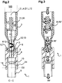
- FIG. 11 shows a cross section along the section line CC according to FIG Figure 1 .
- Figure 3 shows the flow of cleaning fluid through a cleaning device 1. Also in Figure 1 the directions in which cleaning fluid RF is distributed are also shown.
- the cleaning device 1 comprises a housing 2.
- the housing 2 can be detachably or permanently attached to a supply line 100 for a cleaning fluid RF, for example flanged or otherwise connected. Since the supply line 100 is not part of the cleaning device 1, it is only indicated by means of dashed lines.
- the cleaning fluid RF flows through the housing 2. This emerges from the housing 2 via an outlet opening 3.
- a nozzle head 4 is rotatably arranged on the housing 2.
- the nozzle head 4 forms in particular a passage opening 5 for the cleaning fluid RF flowing into the nozzle head 4 from the housing 2 via the outlet opening 3.
- a first support surface 6 is formed on the housing 2 in the area of the outlet opening 3, for example in the form of a crank 7.
- the nozzle head 4 is formed in particular from two half-shell elements which together form a second support surface 8.
- the second bearing surface 8 is designed to correspond to the first bearing surface 6 of the housing 2.
- the nozzle head 4 is arranged on the housing 2 in such a way that a contact point with as little friction as possible is formed between the first contact surface 6 and the second contact surface 8, so that the nozzle head 4 is about a longitudinal axis L2 of the housing 2 or a coaxial longitudinal axis L4 of the nozzle head 4 in the direction of rotation R4 (compare Figure 1 ) can rotate.
- the axis of rotation of the nozzle head 4 is also referred to below as the first axis of rotation D1.
- a distributing device 9 with at least one blade element 10 rotating about a second axis of rotation D2 different from the first axis of rotation D1 is also arranged on the nozzle head 4.
- the housing 2 For fastening to the supply line 100, the housing 2 has a first, cylindrically formed partial area 21. This is followed by a second conically tapering sub-area 22, which in particular merges into a third, likewise cylindrical, sub-area 23, the diameter in the third sub-area 23 being smaller than the diameter in the first sub-area 21.
- a guide element 11 in the form of a spiral element 30 is arranged in the first sub-area 21. This has at least one complete spiral turn and contacts the inner wall surfaces of the housing 2 all around, so that in plan view an entire cross section of the housing 2 in the first partial area 21 is filled by the spiral element 30.
- the housing is completely hollow-cylindrical. If necessary, it can be provided that the inner area of the housing has structures which subdivide the housing into specific functional areas. For example, it can be provided that the above-described taper is formed in the interior of the cylinder.
- the guide element 11 brings about a targeted guidance of the cleaning fluid RF within the housing 2, in particular within the first partial area 21 of the cleaning device 1.
- the cleaning fluid RF is in particular forced to pass through the guide element 11, which is designed as a spiral element 30, completely and in particular without abbreviations.
- the cleaning fluid RF is set in a rotational movement R-RF, the cleaning fluid RF preferably forming a vortex.
- a rotationally movable entrainment element 12 is also arranged.
- This entrainment element 12 has a longitudinal axis L12 coaxial to the longitudinal axis L2 of the housing 2 or coaxial to the longitudinal axis L4 of the nozzle head 4.
- This longitudinal axis L12 of the driver element 12 four vanes 13 rotating about the longitudinal axis L12 are arranged in such a way that the vanes 13 do not touch the inner wall surfaces of the housing 2 in the third sub-area 23 when the driver element 12 rotates around its longitudinal axis L12, but only slightly Game is trained.
- the entrainment element protrudes at least in regions into the nozzle head 4 and is mechanically connected to it.
- the rotation of the cleaning fluid RF causes the entrainment element 12, which is arranged downstream in the direction of movement of the cleaning fluid RF, to rotate R12 (compare in particular Figure 1 ) offset relative to the housing 2.
- the entrainment element 12 is mechanically coupled to the nozzle head 4 in such a way that the rotation R12 of the entrainment element directly causes a rotation R4 of the nozzle head 4.
- the guide element 11 thus serves as the first drive element which effects the rotation R-RF of the cleaning fluid and thus the rotation R4 of the nozzle head 4 through a rotation R12 of the entrainment element 12 generated thereby.
- the cleaning fluid RF emerging from the rotating nozzle head 4 hits the at least one vane element 10 of the distribution device 9.
- the guide element 11 is arranged in the first partial area 21 of the housing 2. But it can also be conical be arranged tapering second partial area 22. In particular, it can be provided that a correspondingly dimensioned guide element (not shown) is loosely inserted into the conically tapering funnel section of the second partial area 22, which is then forced into the correct position by the dynamic pressure of the incoming cleaning fluid RF.
- a defined distance A is formed between the guide element 11 and the entrainment element 12 so that the entrainment element 12 is set in motion, in particular in rotation R12, by the cleaning fluid RF.
- the distribution device 9 is in particular fastened directly to the nozzle head 4 via holding elements 14, so that the distribution device 9 rotates both around the first axis of rotation D1 of the nozzle head 4 and around a second axis of rotation D2, the second axis of rotation D2 being due to the rotation R4 of the nozzle head 4 is variable within a plane of rotation. While the rotation R4 of the nozzle head 4 takes place relatively slowly, the rotation R9 caused by the impact of the cleaning fluid RF on the blade elements 10 of the distribution device 9 is significantly faster. This results in a particularly good distribution of the cleaning fluid RF in all directions, it being possible in particular to avoid a so-called spray shadow, that is to say an area into which no cleaning fluid RF reaches.
- the distribution device 9 is provided with a horizontal offset V (cf. Figure 1 ) arranged to the longitudinal axis L4 of the nozzle head 4, whereby the inflow of cleaning fluid RF from the nozzle head 4 particularly advantageously causes the rotation R9 of the distribution device 9.
- Figure 4 shows a cross section through a driver element 12 and in particular the arrangement of the driver element 12 in the sub-area 23 of the housing 2.
- the driver element 12 has in particular the shape of a Greek cross with four cross arms 15 of equal length which form the wings 13 of the driver element 12. It can be clearly seen that the wings 13 of the driver element 12 each extend approximately to the inner wall surface of the housing 2 extend, but they do not touch them. The driver element 12 can thus rotate freely about its longitudinal axis L12.
- the driving element 12 has as small an end face as possible in cross section, so that the passage area DF for the cleaning fluid RF (cf. Figure 3 ) is as large as possible. A jamming of contaminants in the cleaning fluid RF between the entrainment element 12 and the inner wall surface of the housing 3 can thereby be largely avoided.
- the outer edges of the inlet 100 (cf. Figures 1 and 2 ) facing end face of the entrainment element 12 is angled and act as a comminuting means for any coarse contaminants that may be in the cleaning fluid.
- the edges of the wings 13 of the driver element 12 directed towards the inner wall surfaces of the housing 2 have a slope 16.
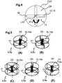
- FIGS 5A to 5H and Figures 6A to 6C show different embodiments of a distribution device 9a to 9l.
- the design or geometry, number and / or arrangement of the blade elements 10 on the distribution device 9 has different effects on the distribution of the cleaning fluid.
- There are forms of blade elements 10 which are preferably offset from the longitudinal axis L4 of the nozzle head 4 (cf. Figures 1 and 2 ) must be operated, while others can deliver the desired result without offset.
- the number and design of the blade elements 10 can be selected and optimally coordinated depending on the requirements placed on the cleaning device 1.
- the distribution devices 9a to 9h shown are each designed as a distribution double wheel, the blade elements 10 each being arranged between two disks 17.
- the two disks 17 can preferably each be designed as solid disks.
- the discs 17 form in particular side edges, which effect a targeted steering of the cleaning fluid to the blade elements 10.
- the blade elements 10a, 10b according to Figures 5A and 5B are designed as curved wings, while the blade elements 10c to 10e according to FIG Figures 5C to 5E are designed as flat or planar wings.
- the Figures 5F to 5H show further distribution devices 9f to 9h with blade elements 10f to 10h that are concave to the axis of rotation D2.
- the distribution devices 9i to 9l according to FIGS Figures 6A to 6c are designed analogously to this, with these embodiments no disks 17 (cf. Figures 5 ) are provided.
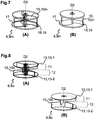
- Figures 7A and 7B as Figures 8A and 8B each show a further embodiment of a distribution device 9m, 9o.
- Figures 7A and 8A show the respective embodiment of the distribution device 9m, 9o in a representation with hidden lines and Figures 7B and 8B show the respective embodiment of the distribution device 9m, 9o in a representation without hidden lines.
- the blade elements 10m are designed as curved blades, the blades not having a uniform thickness. Instead, the wing width tapers in such a way that the wings have the smallest width approximately in the middle between the discs 17, in particular the wings have a sharp bend 18 or an edge 19 in this area, which causes a changed throwing behavior of the cleaning fluid, which under certain Conditions can be beneficial.
- the blade elements 10o are designed as plane wings 13, the wings 13 each extending only approximately halfway between the two disks 17.
- the area between the two panes 17 is divided into two sub-areas T1 and T2.
- the first sub-area T1 three vanes 13-1 extending perpendicular to the axis of rotation D2 are arranged, each of which is offset from one another by an angle of 120 degrees.
- three vanes 13-2 extending perpendicular to the axis of rotation D2 are also arranged, which are also offset from one another by an angle of 120 degrees.
- wings 13-1 in the first sub-area T1 are offset by an angle of 60 degrees to the wings 13-2 in the second sub-area T2. This The split design of the wings 13 also results in a changed throwing-off behavior of the cleaning fluid, which can be advantageous for certain applications.
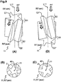
- Figures 9A through 9D show a further embodiment of a guide element 11, in particular FIG Figure 9A a side view of the guide element 11,
- Figure 9B shows a plan view of a guide element 11 according to Figure 9A from above
- Figure 9C shows a plan view of a guide element 11 according to Figure 9A from underneath.
- Figure 9D shows a guide element 11 arranged in reverse.
- the guide element 11 has a longitudinal axis L11 which, in particular, is coaxial or parallel to the first axis of rotation of the distribution device 9 (cf. Figures 1 to 3 ) is aligned.
- the guide element 11 has five paddles 40 arranged around the longitudinal axis L11 of the guide element 11.
- the guide element 11 has an inlet side RF (in) and an outlet side RF (out) for the cleaning fluid RF.
- the cleaning fluid RF enters the guide element 11 via the inlet side RF, passes through this with at least a partial change in the direction of movement and / or movement speed, exits the guide element 11 via the exit side RF and then hits the entrainment element 12 .
- the paddles 40 are positioned at an angle to the longitudinal axis L11 of the guide element 11.
- the slope of the paddles 40 relative to the longitudinal axis L11 of the guide element 11 influences the peripheral speed of the cleaning fluid RF.
- the lower the slope of the paddles 40 the higher the peripheral speed of the cleaning fluid RF on the exit side RF (out).
- the slope of the paddles 40 also has an effect on the intensity of the vortex of cleaning fluid RF that is formed.
- the paddles 40 of the guide element 11 laterally adjoin the inner wall surfaces of the housing 2, so that due to the angular position of the paddles 40 to the longitudinal axis L11 of the guide element 11 in the Top view from the entry side RF (a) forms a partially closed surface, or a partially closed cross section results.
- the width of the paddles 40 in cross-sectional planes perpendicular to the longitudinal axis L11 of the guide element 11 increases from the entry side RF (in) in the direction of the exit side RF (out). Due to a first width B1, there is in particular a first cross section Q1 on the entry side RF (in), which is smaller than a second cross section Q2 on the exit side RF (out) resulting from an increased width B2.
- the different widths B1 and B2 result in a guide element 11 that can be used in different ways.
- Figure 9D shows the arrangement of an inverted guide element 11 in the housing 2 (not shown).
- the width of the paddles 40 decreases in cross-sectional planes perpendicular to the longitudinal axis L11 of the guide element 11 from the entry side RF (in) towards the exit side RF (out) . Due to the first width B1, there is now a cross section Q2 * on the exit side RF (out) which is smaller than a cross section Q1 * on the entry side RF (in) resulting from the increased width B2.
Landscapes
- Engineering & Computer Science (AREA)
- Mechanical Engineering (AREA)
- Nozzles (AREA)
- Cleaning By Liquid Or Steam (AREA)
Priority Applications (1)
| Application Number | Priority Date | Filing Date | Title |
|---|---|---|---|
| PL16759674T PL3337619T3 (pl) | 2015-08-17 | 2016-07-29 | Urządzenie czyszczące i instalacja do przetwarzania produktu |
Applications Claiming Priority (3)
| Application Number | Priority Date | Filing Date | Title |
|---|---|---|---|
| DE102015113559 | 2015-08-17 | ||
| DE102016102727.8A DE102016102727A1 (de) | 2015-08-17 | 2016-02-17 | Reinigungsvorrichtung und produktverarbeitende Anlage |
| PCT/DE2016/000297 WO2017028831A1 (de) | 2015-08-17 | 2016-07-29 | Reinigungsvorrichtung und produktverarbeitende anlage |
Publications (2)
| Publication Number | Publication Date |
|---|---|
| EP3337619A1 EP3337619A1 (de) | 2018-06-27 |
| EP3337619B1 true EP3337619B1 (de) | 2020-10-14 |
Family
ID=57961140
Family Applications (1)
| Application Number | Title | Priority Date | Filing Date |
|---|---|---|---|
| EP16759674.1A Active EP3337619B1 (de) | 2015-08-17 | 2016-07-29 | Reinigungsvorrichtung und produktverarbeitende anlage |
Country Status (8)
| Country | Link |
|---|---|
| US (1) | US11141745B2 (pl) |
| EP (1) | EP3337619B1 (pl) |
| CN (1) | CN107921450B (pl) |
| BR (1) | BR112018001570B1 (pl) |
| DE (1) | DE102016102727A1 (pl) |
| ES (1) | ES2842176T3 (pl) |
| PL (1) | PL3337619T3 (pl) |
| WO (1) | WO2017028831A1 (pl) |
Families Citing this family (5)
| Publication number | Priority date | Publication date | Assignee | Title |
|---|---|---|---|---|
| DE102018215122A1 (de) * | 2018-09-06 | 2020-03-12 | Meiko Maschinenbau Gmbh & Co. Kg | Reinigungsvorrichtung zur Reinigung von Reinigungsgut und Verfahren zur Herstellung einer Reinigungsvorrichtung |
| DE102019107727A1 (de) * | 2019-03-26 | 2020-10-01 | Miele & Cie. Kg | Verteilerscheibe für eine Reinigungsflüssigkeit, Verteilersystem, Gargerät mit einem Garraum und Verfahren zu dessen Reinigung |
| CN110280527A (zh) * | 2019-07-25 | 2019-09-27 | 万静 | 一种新型高速摩擦清洗机 |
| DE102019005831A1 (de) | 2019-08-20 | 2021-02-25 | Gea Tuchenhagen Gmbh | Tankreinigungsvorrichtung und Verfahren |
| DE102020108023A1 (de) | 2020-03-24 | 2021-09-30 | Miele & Cie. Kg | Verteilerscheibe für eine Reinigungsflüssigkeit, Verteilersystem, Gargerät mit einem Garraum und Verfahren zu dessen Reinigung |
Family Cites Families (10)
| Publication number | Priority date | Publication date | Assignee | Title |
|---|---|---|---|---|
| US1352423A (en) * | 1919-04-21 | 1920-09-14 | Arbon Paul | Casing-head |
| DE3617783A1 (de) * | 1986-05-26 | 1987-12-03 | Helmut Becker | Reinigungsvorrichtung fuer behaelter und dergleichen |
| GB8924475D0 (en) | 1989-10-31 | 1989-12-20 | Jeffrey William A | Spray heads |
| DE10126178A1 (de) * | 2001-05-30 | 2002-12-05 | Ralph Kerstner | Einrichtung zur Reinigung des isolierten Innenraumes in Kühltransport-Fahrzeugen |
| US8627838B2 (en) * | 2009-10-02 | 2014-01-14 | Alfa Laval Tank Equipment, Inc. | Rotary impingement cleaning apparatus for sanitary environments |
| DE102011078725A1 (de) | 2011-07-06 | 2013-01-10 | Lechler Gmbh | Rotierende Düsenanordnung |
| DE102011078723A1 (de) | 2011-07-06 | 2013-01-10 | Lechler Gmbh | Rotierende Düsenanordnung |
| DE102011078857A1 (de) * | 2011-07-08 | 2013-01-10 | Lechler Gmbh | Sprühdüse und Verfahren zum Erzeugen wenigstens eines rotierenden Sprühstrahls |
| DE102011080879A1 (de) | 2011-08-12 | 2013-02-14 | Lechler Gmbh | Tankreinigungsdüse |
| WO2013046156A1 (en) * | 2011-09-28 | 2013-04-04 | Sensile Pat Ag | Fluid dispensing system |
-
2016
- 2016-02-17 DE DE102016102727.8A patent/DE102016102727A1/de not_active Withdrawn
- 2016-07-29 US US15/751,810 patent/US11141745B2/en active Active
- 2016-07-29 CN CN201680047544.0A patent/CN107921450B/zh active Active
- 2016-07-29 BR BR112018001570-9A patent/BR112018001570B1/pt active IP Right Grant
- 2016-07-29 WO PCT/DE2016/000297 patent/WO2017028831A1/de not_active Ceased
- 2016-07-29 PL PL16759674T patent/PL3337619T3/pl unknown
- 2016-07-29 ES ES16759674T patent/ES2842176T3/es active Active
- 2016-07-29 EP EP16759674.1A patent/EP3337619B1/de active Active
Non-Patent Citations (1)
| Title |
|---|
| None * |
Also Published As
| Publication number | Publication date |
|---|---|
| BR112018001570A2 (pt) | 2018-09-18 |
| DE102016102727A1 (de) | 2017-02-23 |
| US20180236467A1 (en) | 2018-08-23 |
| ES2842176T3 (es) | 2021-07-13 |
| WO2017028831A1 (de) | 2017-02-23 |
| BR112018001570B1 (pt) | 2021-09-08 |
| CN107921450A (zh) | 2018-04-17 |
| US11141745B2 (en) | 2021-10-12 |
| CN107921450B (zh) | 2019-11-01 |
| PL3337619T3 (pl) | 2021-05-17 |
| EP3337619A1 (de) | 2018-06-27 |
Similar Documents
| Publication | Publication Date | Title |
|---|---|---|
| EP3337619B1 (de) | Reinigungsvorrichtung und produktverarbeitende anlage | |
| EP3370875B1 (de) | Zerkleinerungsvorrichtung und verfahren zum zerkleinern von rohstoffen | |
| EP2978534B1 (de) | Granulatkonditionierer | |
| EP0157250B1 (de) | Vorrichtung zum Beizen von Saatgut | |
| EP0346278A1 (de) | Vorrichtung zum Benetzen von Saatgut | |
| DE661846C (de) | Vorrichtung zum Mischen, Ruehren, Aufloesen, Eindicken, Kneten, Verreiben, Zerkleinern oder Versalben von fliessfaehigen oder bereits pulverfoermigen Massen, vorzugsweise zum Bearbeiten von Kakao- oder Schokolademassen | |
| DE2801460C2 (pl) | ||
| EP2620226B1 (de) | Behälterreinigungsvorrichtung | |
| DE102008057295A1 (de) | Ringspaltdüse | |
| DE1101918B (de) | Einrichtung zum Mischen und/oder Zerkleinern von pulverfoermigem und/oder fluessigem Gut | |
| DE3415719A1 (de) | Verfahren zur freilegung von sojabohnenkernen | |
| DE4232948C2 (de) | Gegenstrom-Fadensichter und Verfahren zur Reinigung von Granulat mittels dieses Fadensichters | |
| DE3209309C2 (pl) | ||
| DE830604C (de) | Prallmuehle, insbesondere zum Mahlen von Weizen und anderem Getreide | |
| DE423433C (de) | Vorrichtung zum Zerstaeuben von Fluessigkeiten, zum Konzentrieren von Loesungen, zum Homogenisieren von Suspensionen bzw. zur Durchfuehrung chemischer Reaktionen innerhalb zerstaeubter Stoffe | |
| CH304025A (de) | Misch- und Dispergiervorrichtung. | |
| DE1454753A1 (de) | Granuliereinrichtung | |
| WO2002075228A1 (de) | Mit einer zerstäubungseinrichtung für flüssigkeiten versehene schneekanone | |
| EP3300793B1 (de) | Vorrichtung zum mischen eines pulverförmigen guts mit einer flüssigkeit | |
| DE441194C (de) | Vorrichtung zum Zerstaeuben von Fluessigkeiten | |
| EP3106228B1 (de) | Vorrichtung und mahlwerkzeug zum zerkleinern von aufgabegut | |
| DE19943670A1 (de) | Verfahren zur Fließbettstrahlmahlung, Vorrichtung zur Durchführung dieses Verfahrens und Anlage mit einer solchen Vorrichtung zur Durchführung dieses Verfahrens | |
| DE102009006443B3 (de) | Vorrichtung zur Zugabe von Flüssigkeit in eine Mischvorrichtung | |
| EP0403794B1 (de) | Spritzvorrichtung für Flaschenreinigungsmaschinen | |
| DE1963264C3 (de) | Vorrichtung zum Zerkleinern eines Materials |
Legal Events
| Date | Code | Title | Description |
|---|---|---|---|
| STAA | Information on the status of an ep patent application or granted ep patent |
Free format text: STATUS: THE INTERNATIONAL PUBLICATION HAS BEEN MADE |
|
| PUAI | Public reference made under article 153(3) epc to a published international application that has entered the european phase |
Free format text: ORIGINAL CODE: 0009012 |
|
| STAA | Information on the status of an ep patent application or granted ep patent |
Free format text: STATUS: REQUEST FOR EXAMINATION WAS MADE |
|
| 17P | Request for examination filed |
Effective date: 20180122 |
|
| AK | Designated contracting states |
Kind code of ref document: A1 Designated state(s): AL AT BE BG CH CY CZ DE DK EE ES FI FR GB GR HR HU IE IS IT LI LT LU LV MC MK MT NL NO PL PT RO RS SE SI SK SM TR |
|
| AX | Request for extension of the european patent |
Extension state: BA ME |
|
| DAV | Request for validation of the european patent (deleted) | ||
| DAX | Request for extension of the european patent (deleted) | ||
| GRAP | Despatch of communication of intention to grant a patent |
Free format text: ORIGINAL CODE: EPIDOSNIGR1 |
|
| STAA | Information on the status of an ep patent application or granted ep patent |
Free format text: STATUS: GRANT OF PATENT IS INTENDED |
|
| INTG | Intention to grant announced |
Effective date: 20200622 |
|
| GRAS | Grant fee paid |
Free format text: ORIGINAL CODE: EPIDOSNIGR3 |
|
| GRAA | (expected) grant |
Free format text: ORIGINAL CODE: 0009210 |
|
| STAA | Information on the status of an ep patent application or granted ep patent |
Free format text: STATUS: THE PATENT HAS BEEN GRANTED |
|
| AK | Designated contracting states |
Kind code of ref document: B1 Designated state(s): AL AT BE BG CH CY CZ DE DK EE ES FI FR GB GR HR HU IE IS IT LI LT LU LV MC MK MT NL NO PL PT RO RS SE SI SK SM TR |
|
| REG | Reference to a national code |
Ref country code: GB Ref legal event code: FG4D Free format text: NOT ENGLISH |
|
| REG | Reference to a national code |
Ref country code: AT Ref legal event code: REF Ref document number: 1323056 Country of ref document: AT Kind code of ref document: T Effective date: 20201015 Ref country code: CH Ref legal event code: EP |
|
| REG | Reference to a national code |
Ref country code: DE Ref legal event code: R096 Ref document number: 502016011455 Country of ref document: DE |
|
| REG | Reference to a national code |
Ref country code: IE Ref legal event code: FG4D Free format text: LANGUAGE OF EP DOCUMENT: GERMAN |
|
| REG | Reference to a national code |
Ref country code: NL Ref legal event code: FP |
|
| PG25 | Lapsed in a contracting state [announced via postgrant information from national office to epo] |
Ref country code: FI Free format text: LAPSE BECAUSE OF FAILURE TO SUBMIT A TRANSLATION OF THE DESCRIPTION OR TO PAY THE FEE WITHIN THE PRESCRIBED TIME-LIMIT Effective date: 20201014 Ref country code: GR Free format text: LAPSE BECAUSE OF FAILURE TO SUBMIT A TRANSLATION OF THE DESCRIPTION OR TO PAY THE FEE WITHIN THE PRESCRIBED TIME-LIMIT Effective date: 20210115 Ref country code: NO Free format text: LAPSE BECAUSE OF FAILURE TO SUBMIT A TRANSLATION OF THE DESCRIPTION OR TO PAY THE FEE WITHIN THE PRESCRIBED TIME-LIMIT Effective date: 20210114 Ref country code: PT Free format text: LAPSE BECAUSE OF FAILURE TO SUBMIT A TRANSLATION OF THE DESCRIPTION OR TO PAY THE FEE WITHIN THE PRESCRIBED TIME-LIMIT Effective date: 20210215 Ref country code: RS Free format text: LAPSE BECAUSE OF FAILURE TO SUBMIT A TRANSLATION OF THE DESCRIPTION OR TO PAY THE FEE WITHIN THE PRESCRIBED TIME-LIMIT Effective date: 20201014 |
|
| REG | Reference to a national code |
Ref country code: LT Ref legal event code: MG4D |
|
| PG25 | Lapsed in a contracting state [announced via postgrant information from national office to epo] |
Ref country code: IS Free format text: LAPSE BECAUSE OF FAILURE TO SUBMIT A TRANSLATION OF THE DESCRIPTION OR TO PAY THE FEE WITHIN THE PRESCRIBED TIME-LIMIT Effective date: 20210214 Ref country code: LV Free format text: LAPSE BECAUSE OF FAILURE TO SUBMIT A TRANSLATION OF THE DESCRIPTION OR TO PAY THE FEE WITHIN THE PRESCRIBED TIME-LIMIT Effective date: 20201014 Ref country code: BG Free format text: LAPSE BECAUSE OF FAILURE TO SUBMIT A TRANSLATION OF THE DESCRIPTION OR TO PAY THE FEE WITHIN THE PRESCRIBED TIME-LIMIT Effective date: 20210114 Ref country code: SE Free format text: LAPSE BECAUSE OF FAILURE TO SUBMIT A TRANSLATION OF THE DESCRIPTION OR TO PAY THE FEE WITHIN THE PRESCRIBED TIME-LIMIT Effective date: 20201014 |
|
| PG25 | Lapsed in a contracting state [announced via postgrant information from national office to epo] |
Ref country code: HR Free format text: LAPSE BECAUSE OF FAILURE TO SUBMIT A TRANSLATION OF THE DESCRIPTION OR TO PAY THE FEE WITHIN THE PRESCRIBED TIME-LIMIT Effective date: 20201014 |
|
| REG | Reference to a national code |
Ref country code: ES Ref legal event code: FG2A Ref document number: 2842176 Country of ref document: ES Kind code of ref document: T3 Effective date: 20210713 |
|
| REG | Reference to a national code |
Ref country code: DE Ref legal event code: R097 Ref document number: 502016011455 Country of ref document: DE |
|
| PG25 | Lapsed in a contracting state [announced via postgrant information from national office to epo] |
Ref country code: SK Free format text: LAPSE BECAUSE OF FAILURE TO SUBMIT A TRANSLATION OF THE DESCRIPTION OR TO PAY THE FEE WITHIN THE PRESCRIBED TIME-LIMIT Effective date: 20201014 Ref country code: RO Free format text: LAPSE BECAUSE OF FAILURE TO SUBMIT A TRANSLATION OF THE DESCRIPTION OR TO PAY THE FEE WITHIN THE PRESCRIBED TIME-LIMIT Effective date: 20201014 Ref country code: CZ Free format text: LAPSE BECAUSE OF FAILURE TO SUBMIT A TRANSLATION OF THE DESCRIPTION OR TO PAY THE FEE WITHIN THE PRESCRIBED TIME-LIMIT Effective date: 20201014 Ref country code: EE Free format text: LAPSE BECAUSE OF FAILURE TO SUBMIT A TRANSLATION OF THE DESCRIPTION OR TO PAY THE FEE WITHIN THE PRESCRIBED TIME-LIMIT Effective date: 20201014 Ref country code: SM Free format text: LAPSE BECAUSE OF FAILURE TO SUBMIT A TRANSLATION OF THE DESCRIPTION OR TO PAY THE FEE WITHIN THE PRESCRIBED TIME-LIMIT Effective date: 20201014 Ref country code: LT Free format text: LAPSE BECAUSE OF FAILURE TO SUBMIT A TRANSLATION OF THE DESCRIPTION OR TO PAY THE FEE WITHIN THE PRESCRIBED TIME-LIMIT Effective date: 20201014 |
|
| PLBE | No opposition filed within time limit |
Free format text: ORIGINAL CODE: 0009261 |
|
| STAA | Information on the status of an ep patent application or granted ep patent |
Free format text: STATUS: NO OPPOSITION FILED WITHIN TIME LIMIT |
|
| PG25 | Lapsed in a contracting state [announced via postgrant information from national office to epo] |
Ref country code: DK Free format text: LAPSE BECAUSE OF FAILURE TO SUBMIT A TRANSLATION OF THE DESCRIPTION OR TO PAY THE FEE WITHIN THE PRESCRIBED TIME-LIMIT Effective date: 20201014 |
|
| 26N | No opposition filed |
Effective date: 20210715 |
|
| PG25 | Lapsed in a contracting state [announced via postgrant information from national office to epo] |
Ref country code: AL Free format text: LAPSE BECAUSE OF FAILURE TO SUBMIT A TRANSLATION OF THE DESCRIPTION OR TO PAY THE FEE WITHIN THE PRESCRIBED TIME-LIMIT Effective date: 20201014 |
|
| PG25 | Lapsed in a contracting state [announced via postgrant information from national office to epo] |
Ref country code: SI Free format text: LAPSE BECAUSE OF FAILURE TO SUBMIT A TRANSLATION OF THE DESCRIPTION OR TO PAY THE FEE WITHIN THE PRESCRIBED TIME-LIMIT Effective date: 20201014 |
|
| GBPC | Gb: european patent ceased through non-payment of renewal fee |
Effective date: 20210729 |
|
| PG25 | Lapsed in a contracting state [announced via postgrant information from national office to epo] |
Ref country code: MC Free format text: LAPSE BECAUSE OF FAILURE TO SUBMIT A TRANSLATION OF THE DESCRIPTION OR TO PAY THE FEE WITHIN THE PRESCRIBED TIME-LIMIT Effective date: 20201014 |
|
| PG25 | Lapsed in a contracting state [announced via postgrant information from national office to epo] |
Ref country code: GB Free format text: LAPSE BECAUSE OF NON-PAYMENT OF DUE FEES Effective date: 20210729 |
|
| PG25 | Lapsed in a contracting state [announced via postgrant information from national office to epo] |
Ref country code: IS Free format text: LAPSE BECAUSE OF FAILURE TO SUBMIT A TRANSLATION OF THE DESCRIPTION OR TO PAY THE FEE WITHIN THE PRESCRIBED TIME-LIMIT Effective date: 20210214 Ref country code: LU Free format text: LAPSE BECAUSE OF NON-PAYMENT OF DUE FEES Effective date: 20210729 |
|
| PG25 | Lapsed in a contracting state [announced via postgrant information from national office to epo] |
Ref country code: IE Free format text: LAPSE BECAUSE OF NON-PAYMENT OF DUE FEES Effective date: 20210729 |
|
| REG | Reference to a national code |
Ref country code: AT Ref legal event code: MM01 Ref document number: 1323056 Country of ref document: AT Kind code of ref document: T Effective date: 20210729 |
|
| PG25 | Lapsed in a contracting state [announced via postgrant information from national office to epo] |
Ref country code: AT Free format text: LAPSE BECAUSE OF NON-PAYMENT OF DUE FEES Effective date: 20210729 |
|
| PG25 | Lapsed in a contracting state [announced via postgrant information from national office to epo] |
Ref country code: HU Free format text: LAPSE BECAUSE OF FAILURE TO SUBMIT A TRANSLATION OF THE DESCRIPTION OR TO PAY THE FEE WITHIN THE PRESCRIBED TIME-LIMIT; INVALID AB INITIO Effective date: 20160729 |
|
| PG25 | Lapsed in a contracting state [announced via postgrant information from national office to epo] |
Ref country code: CY Free format text: LAPSE BECAUSE OF FAILURE TO SUBMIT A TRANSLATION OF THE DESCRIPTION OR TO PAY THE FEE WITHIN THE PRESCRIBED TIME-LIMIT Effective date: 20201014 |
|
| PG25 | Lapsed in a contracting state [announced via postgrant information from national office to epo] |
Ref country code: MK Free format text: LAPSE BECAUSE OF FAILURE TO SUBMIT A TRANSLATION OF THE DESCRIPTION OR TO PAY THE FEE WITHIN THE PRESCRIBED TIME-LIMIT Effective date: 20201014 |
|
| PG25 | Lapsed in a contracting state [announced via postgrant information from national office to epo] |
Ref country code: MT Free format text: LAPSE BECAUSE OF FAILURE TO SUBMIT A TRANSLATION OF THE DESCRIPTION OR TO PAY THE FEE WITHIN THE PRESCRIBED TIME-LIMIT Effective date: 20201014 |
|
| PGFP | Annual fee paid to national office [announced via postgrant information from national office to epo] |
Ref country code: PL Payment date: 20250630 Year of fee payment: 10 |
|
| PGFP | Annual fee paid to national office [announced via postgrant information from national office to epo] |
Ref country code: NL Payment date: 20250724 Year of fee payment: 10 |
|
| PGFP | Annual fee paid to national office [announced via postgrant information from national office to epo] |
Ref country code: ES Payment date: 20250801 Year of fee payment: 10 |
|
| PGFP | Annual fee paid to national office [announced via postgrant information from national office to epo] |
Ref country code: DE Payment date: 20250730 Year of fee payment: 10 |
|
| PGFP | Annual fee paid to national office [announced via postgrant information from national office to epo] |
Ref country code: IT Payment date: 20250729 Year of fee payment: 10 |
|
| PGFP | Annual fee paid to national office [announced via postgrant information from national office to epo] |
Ref country code: BE Payment date: 20250723 Year of fee payment: 10 |
|
| PGFP | Annual fee paid to national office [announced via postgrant information from national office to epo] |
Ref country code: FR Payment date: 20250729 Year of fee payment: 10 |
|
| PGFP | Annual fee paid to national office [announced via postgrant information from national office to epo] |
Ref country code: CH Payment date: 20250801 Year of fee payment: 10 |
|
| PG25 | Lapsed in a contracting state [announced via postgrant information from national office to epo] |
Ref country code: TR Free format text: LAPSE BECAUSE OF FAILURE TO SUBMIT A TRANSLATION OF THE DESCRIPTION OR TO PAY THE FEE WITHIN THE PRESCRIBED TIME-LIMIT Effective date: 20201014 |