EP3336986B1 - Device for guiding at least two lines, as well as a connecting material comprising such a device - Google Patents
Device for guiding at least two lines, as well as a connecting material comprising such a device Download PDFInfo
- Publication number
- EP3336986B1 EP3336986B1 EP17204341.6A EP17204341A EP3336986B1 EP 3336986 B1 EP3336986 B1 EP 3336986B1 EP 17204341 A EP17204341 A EP 17204341A EP 3336986 B1 EP3336986 B1 EP 3336986B1
- Authority
- EP
- European Patent Office
- Prior art keywords
- lines
- basic body
- section
- slide
- material according
- Prior art date
- Legal status (The legal status is an assumption and is not a legal conclusion. Google has not performed a legal analysis and makes no representation as to the accuracy of the status listed.)
- Active
Links
- 239000000463 material Substances 0.000 title claims description 30
- 239000004020 conductor Substances 0.000 claims description 10
- 239000011810 insulating material Substances 0.000 claims description 8
- 239000004800 polyvinyl chloride Substances 0.000 claims description 7
- 229920000915 polyvinyl chloride Polymers 0.000 claims description 6
- 229920003023 plastic Polymers 0.000 claims description 4
- 239000004033 plastic Substances 0.000 claims description 4
- 230000005540 biological transmission Effects 0.000 description 4
- 230000001681 protective effect Effects 0.000 description 4
- 239000002390 adhesive tape Substances 0.000 description 3
- 238000010276 construction Methods 0.000 description 2
- 239000013013 elastic material Substances 0.000 description 2
- 208000027418 Wounds and injury Diseases 0.000 description 1
- 230000008878 coupling Effects 0.000 description 1
- 238000010168 coupling process Methods 0.000 description 1
- 238000005859 coupling reaction Methods 0.000 description 1
- 230000006378 damage Effects 0.000 description 1
- 230000007423 decrease Effects 0.000 description 1
- 238000011161 development Methods 0.000 description 1
- 230000018109 developmental process Effects 0.000 description 1
- 230000000694 effects Effects 0.000 description 1
- 208000014674 injury Diseases 0.000 description 1
- 238000009434 installation Methods 0.000 description 1
- 238000009413 insulation Methods 0.000 description 1
- 230000007935 neutral effect Effects 0.000 description 1
- 239000012811 non-conductive material Substances 0.000 description 1
- 230000008054 signal transmission Effects 0.000 description 1
- 239000007787 solid Substances 0.000 description 1
Images


Classifications
-
- H—ELECTRICITY
- H02—GENERATION; CONVERSION OR DISTRIBUTION OF ELECTRIC POWER
- H02G—INSTALLATION OF ELECTRIC CABLES OR LINES, OR OF COMBINED OPTICAL AND ELECTRIC CABLES OR LINES
- H02G1/00—Methods or apparatus specially adapted for installing, maintaining, repairing or dismantling electric cables or lines
- H02G1/06—Methods or apparatus specially adapted for installing, maintaining, repairing or dismantling electric cables or lines for laying cables, e.g. laying apparatus on vehicle
- H02G1/08—Methods or apparatus specially adapted for installing, maintaining, repairing or dismantling electric cables or lines for laying cables, e.g. laying apparatus on vehicle through tubing or conduit, e.g. rod or draw wire for pushing or pulling
- H02G1/085—Methods or apparatus specially adapted for installing, maintaining, repairing or dismantling electric cables or lines for laying cables, e.g. laying apparatus on vehicle through tubing or conduit, e.g. rod or draw wire for pushing or pulling using portable tools
-
- H—ELECTRICITY
- H02—GENERATION; CONVERSION OR DISTRIBUTION OF ELECTRIC POWER
- H02G—INSTALLATION OF ELECTRIC CABLES OR LINES, OR OF COMBINED OPTICAL AND ELECTRIC CABLES OR LINES
- H02G3/00—Installations of electric cables or lines or protective tubing therefor in or on buildings, equivalent structures or vehicles
- H02G3/02—Details
- H02G3/04—Protective tubing or conduits, e.g. cable ladders or cable troughs
- H02G3/0462—Tubings, i.e. having a closed section
- H02G3/0481—Tubings, i.e. having a closed section with a circular cross-section
Definitions
- the present invention relates to a connection material for transmitting a broadband powerline signal via a power supply network.
- an energy supply network is used to exchange communication signals between the participants in the system.
- the signals or data to be transmitted are modulated in the higher frequency range on one or more lines of the power supply network, for example on one phase relative to the neutral conductor or between two phases.
- BPL Powerline Communication - broadband powerline
- the lines of the connection material that is used to couple a BPL signal in or out of an electrical system it is necessary to route them in as exact an alignment as possible. This is problematic insofar as, in particular, the section of the connection material that is coupled to an electrical system, for example a street distributor, is present as individually routed, separate lines. Since the lines in this section do not run in a defined position to one another, the wave impedance of the lines increases, which sometimes leads to strong attenuation of the BPL signal.
- the US 2007/0277995 A1 shows a double cable for headphones, a first cable being surrounded by slotted insulation.
- a second cable can be introduced into the slot with the aid of a slider and removed from it.
- the CH 384 355 A , WO 02/052686 A2 and DE 10 2007 038 327 A1 also describe devices for guiding a cable. Furthermore, the documents concern WO 2005/074214 A1 and EP 2 437 074 A2 the transmission of a broadband powerline signal.
- the present invention is based on the object of specifying a connection material in which the lines can be guided at a defined distance from one another using structurally simple means.
- the disclosure further relates to a device for guiding at least two lines, in particular for data transmission, specified, comprising a base body for receiving the lines, the base body having at least in some areas a slot extending in the longitudinal direction, a slide being arranged on the base body, wherein the slide can be moved along the longitudinal direction of the base body and wherein at least one of the lines can be introduced into the base body and / or removed from the base body by means of the slide through the slot.
- the arrangement of a base body accommodating the lines allows the lines to be guided in a simple manner in a defined position to one another. Furthermore, the base body has a slot running in the longitudinal direction of the base body, through which at least one of the lines can be introduced into the base body or removed from it.
- a slide is provided for this purpose, which can be moved along the longitudinal direction of the base body and via which at least one of the lines is pushed into and / or pulled out of the base body through the slot, depending on the direction in which the slide is moved.
- the device is very easy to handle even in a confined space and with protective gloves.
- lines can be led extremely easily to one another in a defined position and also removed from one another or detached again, so that the device can be used extremely flexibly and multiple use is also possible.
- Another advantage is that the line in contact with the slide is at least slightly secured by the slide against further withdrawal and / or introduction into the base body.
- the base body is advantageously designed in one piece.
- the base body consists of several individual parts. It is essential that the lines located in the main body are guided to one another in a defined position and that at least one of the lines can be introduced through the slot into the main body or a cavity formed in the main body and can be removed from it.
- a slot is to be understood as an opening which is sufficiently large to allow a line to pass through.
- the edges of the slot can be at least slightly pretensioned so that they are essentially against one another when the line has passed the slot. It is thereby achieved that the opening made by the slot is at least substantially closed and the line is securely received in the base body.
- a line is to be understood as an electrical conductor for transmitting a signal, in particular a BPL signal, which has an insulating sheath.
- a single-core cable comprises only a single conductor.
- One multi-core cable is formed by at least two mutually insulated, combined conductors.
- the lines advantageously run essentially parallel to one another within the base body. This ensures that the wave impedance of the lines is minimized, so that the attenuation of the signal to be transmitted is reduced. In particular, it is advantageous if the lines run with the smallest possible spacing from one another.
- the base body has an elongated shape.
- the base body can, for example, be designed to be essentially straight.
- the geometry of the base body is adapted to the installation situation, the base body is designed, for example, curved. It is essential that the lines within the base body run in a defined orientation - preferably parallel - to one another.
- the base body is designed as a tube, the tube not necessarily having to have a round cross section.
- the pipe can for example consist of a non-conductive material, in particular polyvinyl chloride (PVC).
- PVC polyvinyl chloride
- the lines can be introduced into the pipe through the slot extending in the longitudinal direction, at least one of the lines being able to be introduced into the pipe and / or out of the pipe by means of the slide which can be moved along the pipe.
- two slots are formed on the base body.
- the slots can be implemented, for example, on opposite sides of the base body, so that the electrical lines can each be introduced into and removed from the base body through their own, separate slot. It is conceivable that two cavities which are separate from one another run in the base body, one of the slots in each case realizing a passage to one of the cavities. As a result, the conductors can be received in separate cavities in the base body.
- the term cavity is to be understood in the broadest sense in relation to the device according to the invention, namely it is only necessary that one or more lines can be arranged within the base body.
- the base body can consist of an elastic material and be essentially solid or filled with an elastic material, so that the required cavity is created by the introduction of the line.
- the slide can at least partially enclose the base body - in the circumferential direction.
- the slide is securely arranged on the base body and can be moved along the longitudinal direction of the base body.
- the slide can be a ring that is pushed over the base body.
- the line can be pushed into or pulled out of the base body by moving the ring.
- the slide partially encloses the base body in the circumferential direction, so that the slide is connected to the base body in a fixed manner and movable in the longitudinal direction. Any form-fitting and / or non-positive connection between the base body and slide is conceivable, which enables the slide to be moved in the longitudinal direction of the base body.
- the slide can be fixed at least in a defined position on the base body, for example it can be clamped or latched, so that a movement in the longitudinal direction is prevented.
- the position is defined in which it penetrates the base body or exits it.
- the slide has at least one passage through which the line is passed.
- the line is pulled out of or inserted into the base body, depending on the direction of movement of the slide.
- the slide has several passages, corresponding to the number of electrical lines, so that each of the lines can be passed through a separate passage.
- several lines can be passed through a single passage.
- the slide is made of a non-conductive or poorly conductive material.
- This can be a plastic, for example polyvinyl chloride.
- the base body is at least partially filled with an insulating material, in particular polyvinyl chloride.
- the lines are insulated again by the insulating material and it is also possible to route the lines more precisely, namely due to the reduced cavity within the base body.
- a slot extending in the longitudinal direction of the base body is formed in the insulating material at least in some areas. A line can be passed through the slot and thus introduced into the base body.
- connection material for the transmission of a broadband powerline signal via a power supply network with a first section consisting of a multi-core, in particular three-core, line and a second section consisting of two separate, in particular single-core, lines, the first section and the second Section are connected to each other, wherein a connection element for connecting to a broadband powerline modem is formed at a free end of the multi-core line of the first section, and at least at a free end of the lines of the second section a connection element for connecting to a connection means electrical system is formed, characterized in that a base body is arranged for receiving at least one area of the lines of the second section, that the base body has at least in some areas a slot extending in the longitudinal direction of the base body, that a Slide is arranged on the base body, that the slide can be moved along the longitudinal direction of the base body and has at least one passage for at least one line, that at least one of the lines can be introduced into the base body and
- a connecting element for connecting to an electrical device is formed at the free end of the multi-core line of the first section.
- This can be, for example, a plug connector that is designed to be connected to a broadband powerline modem.
- the Fig. 1 and 2 show a schematic representation of a first exemplary embodiment of part of a connection material according to the invention.
- This has a base body 1 for receiving at least two lines 2, 2 '.
- a slide 3, which can be displaced along the longitudinal direction of the base body 1, is arranged on the base body 1.
- the base body 1 has a slot 4, which likewise extends in the longitudinal direction of the base body 1.
- the line 2 can be introduced into the cavity 5 of the base body 1 through the slot 4.
- the slide 2 has a passage 6 through which the line 2 is passed.
- the line 2 - depending on the direction of movement - is pressed or inserted into the base body 1 or pulled out of the base body 1 or brought out.
- the slide 2 can also be very easily operate when the fitter is wearing protective gloves and there is little space available for handling the device.
- a second cavity 5 ' is formed, which is used to receive the second line 2'.
- the cavities 5, 5 ' are separated from one another by an insulating material 7, for example PVC.
- the base body 1 is designed in one piece.
- the insulating material 7 also has a slot running in the longitudinal direction in order to introduce the second line 2 'through the slot into the cavity 5'.
- a further slot can be formed on the base body 1, through which the second line 2 'can be introduced into the cavity 5' or removed from it.
- the line 2 ' is essentially fixedly arranged in the cavity 5' and only the line 2 can be removed from the cavity 5 and thus from the base body 1 and can be reintroduced.
- edges 8 of the slot 4 almost touch each other, so that the cavity 5 is essentially closed when the line 2 is brought in or out.
- the edges 8 can be pretensioned in such a way that they touch each other when the line 2 is inserted or removed.
- Fig. 3 and 4th is the slide 3 of the in the Fig. 1 and 2 shown embodiment.
- the slide 3 has a radially inwardly extending projection 9 with which it engages in the slot 4 of the base body 1.
- the projection 9 prevents the slide 3 from rotating relative to the base body 2.
- the projection 9 spreads the edges 8 apart so that the line 1 can be brought in or out more easily.
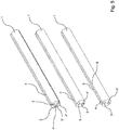
- Fig. 5 several configurations of the base body 1 are shown. This can accommodate, for example, two or three lines 2, 2 ', 2 ". Depending on how many cavities 5, 5', 5" have a slot 4, the slide 3 is to be adapted accordingly, namely according to the figure shown in FIG Fig. 2 and 3 illustrated embodiment.
- FIG. 6 to 9 a further embodiment of a part of a connection material according to the invention is shown.
- This comprises a base body 1 for receiving two lines 2, 2 '.
- the line 2 can be introduced into and removed from the base body 1 through a slider 3 through the slot 4.
- the slide 3 surrounds the base body 1 and has a projection 9 with which it engages in the slot 4.
- the slide 3 can be made from a bent wire.
- the slide 3 is made of a plastic.
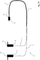
- Fig. 10 shows a schematic representation of part of a connection material according to the invention.
- the connection material has a first section 10, which consists of a three-wire line 11.
- the first section 10 is connected to the second section 12.
- the second section 12 consists of two separate, single-core lines 2, 2 '.
- a plug connector 14 for coupling to a broadband powerline modem is formed.
- the free ends 15 of the lines 2, 2 'of the second section each have a connection element 16 for connecting to a connection means of an electrical system, in particular a low-voltage high-performance load strip.
- the lines 2, 2' are arranged or guided at least in some areas in a device according to the invention. It is thereby achieved that the conductors 2, 2 'are guided at a defined, small distance from one another, the distance at most varying slightly over the length of the lines 2, 2'. With such an arrangement, the wave impedance of the conductors is minimized, which leads to an improvement in the signal transmission.
Description
Die vorliegende Erfindung betrifft ein Anschlussmaterial zur Übertragung eines Breitband-Powerline-Signals über eine Energieversorgungsnetzwerk.The present invention relates to a connection material for transmitting a broadband powerline signal via a power supply network.
Aus der Praxis ist es bekannt, elektrische Leitungen durch unterschiedliche Verbindungselemente wie zum Beispiel Kabelbinder, Klebeband etc. miteinander zu verbinden, um die Leitungen geordnet zu führen. Dazu werden die elektrischen Leitungen mit den Verbindungselementen in mehr oder weniger regelmäßigen Abständen miteinander verbunden. Des Weiteren sind Kabelkanäle - bspw. an Büromöbeln - bekannt, welche zum Führen der elektrischen Leitungen dienen.It is known from practice to connect electrical lines to one another using different connecting elements such as cable ties, adhesive tape, etc., in order to guide the lines in an orderly manner. For this purpose, the electrical lines are connected to one another with the connecting elements at more or less regular intervals. Furthermore, cable ducts - for example on office furniture - are known which are used to guide the electrical lines.
Insbesondere bei elektrischen Leitungen von Powerline Communication-Systemen gelten besondere Anforderungen bezüglich der Führung von elektrischen Leitungen. Bei Powerline Communication-Systemen wird ein Energieversorgungsnetzwerk zum Austausch von Kommunikationssignalen zwischen den Teilnehmern des Systems genutzt. Die zu übertragenden Signale bzw. Daten werden im höherfrequenten Bereich auf eine oder mehrere Leitungen des Energieversorgungsnetzwerks moduliert, beispielsweise auf eine Phase relativ zum Neutralleiter oder zwischen zwei Phasen. Bei der Breitbandvariante von Powerline Communication - Breitband-Powerline (BPL) - werden beispielsweise häufig Signalanteile im Frequenzbereich zwischen 1 und 30 MHz verwendet.Particularly in the case of electrical lines of powerline communication systems, special requirements apply with regard to the routing of electrical lines. In powerline communication systems, an energy supply network is used to exchange communication signals between the participants in the system. The signals or data to be transmitted are modulated in the higher frequency range on one or more lines of the power supply network, for example on one phase relative to the neutral conductor or between two phases. In the broadband variant of Powerline Communication - broadband powerline (BPL) - for example, signal components in the frequency range between 1 and 30 MHz are often used.
Bei den Leitungen des Anschlussmaterials, das zum Ein- bzw. Auskoppeln eines BPL-Signals von einer elektrischen Anlage dient, ist es notwendig, diese in einer möglichst exakten Ausrichtung zueinander zu führen. Dies ist insofern problematisch, da insbesondere der Abschnitt des Anschlussmaterials, der mit einer elektrischen Anlage, beispielsweise einem Straßenverteiler, gekoppelt wird, als einzeln geführte, separate Leitungen vorliegt. Da die Leitungen dieses Abschnitts nicht in einer definierten Position zueinander verlaufen, nimmt die Wellenimpedanz der Leitungen zu, was zu einer mitunter starken Dämpfung des BPL-Signals führt.In the case of the lines of the connection material that is used to couple a BPL signal in or out of an electrical system, it is necessary to route them in as exact an alignment as possible. This is problematic insofar as, in particular, the section of the connection material that is coupled to an electrical system, for example a street distributor, is present as individually routed, separate lines. Since the lines in this section do not run in a defined position to one another, the wave impedance of the lines increases, which sometimes leads to strong attenuation of the BPL signal.
Das Zusammenführen der einzeln geführten Leitungen mittels Kabelbinder, Klebeband etc. ist problematisch, da die elektrische Anlage regelmäßig unter Spannung steht, wenn der Monteur die Leitungen mit der Anlage verbindet. Dabei werden von dem Monteur Schutzhandschuhe getragen und ist der zur Verfügung stehende Raum sehr beengt, so dass die Arbeit mit Klebeband, Kabelbindern etc. äußerst schwierig ist.Bringing the individually routed lines together using cable ties, adhesive tape, etc. is problematic because the electrical system is regularly under voltage when the fitter connects the lines to the system. The fitter wears protective gloves and is available Standing space is very cramped, so that working with adhesive tape, cable ties, etc. is extremely difficult.
Des Weiteren ist es aufgrund der voranstehend beschriebenen Arbeitsbedingungen nur schwer möglich, diese Verbindungselemente wieder zu öffnen, um die miteinander verbundenen Leitungen voneinander zu trennen, zumal für den Monteur aufgrund der anliegenden Spannung ein erhebliches Verletzungsrisiko besteht. Ein weiterer Nachteil besteht darin, dass die Leitungen lediglich im Bereich der Verbindungselemente einen definierten Abstand zueinander aufweisen. Somit schwankt der Abstand der Leitungen über die Länge hinweg, was sich negativ auf die Wellenimpedanz und somit die Dämpfung des BPL-Signals auswirkt.Furthermore, due to the working conditions described above, it is only possible with difficulty to open these connecting elements again in order to separate the interconnected lines from one another, especially since there is a considerable risk of injury for the fitter due to the applied voltage. Another disadvantage is that the lines have a defined distance from one another only in the area of the connecting elements. The distance between the lines thus fluctuates over the length, which has a negative effect on the wave impedance and thus the attenuation of the BPL signal.
Die
Die
Der vorliegenden Erfindung liegt die Aufgabe zugrunde, ein Anschlussmaterial anzugeben, bei dem mit konstruktiv einfachen Mittel eine Führung der Leitungen in einem definierten Abstand zueinander möglich ist.The present invention is based on the object of specifying a connection material in which the lines can be guided at a defined distance from one another using structurally simple means.
Die Offenbarung betrifft des Weiteren eine Vorrichtung zum Führen von mindestens zwei Leitungen, insbesondere zur Datenübertragung, angegeben, umfassend einen Grundkörper zur Aufnahme der Leitungen, wobei der Grundkörper zumindest bereichsweise einen sich in Längsrichtung erstreckenden Schlitz aufweist, wobei ein Schieber an dem Grundkörper angeordnet ist, wobei der Schieber entlang der Längsrichtung des Grundkörpers bewegbar ist und wobei zumindest eine der Leitungen mittels des Schiebers durch den Schlitz in den Grundkörper einbringbar und/oder aus dem Grundkörper ausbringbar ist.The disclosure further relates to a device for guiding at least two lines, in particular for data transmission, specified, comprising a base body for receiving the lines, the base body having at least in some areas a slot extending in the longitudinal direction, a slide being arranged on the base body, wherein the slide can be moved along the longitudinal direction of the base body and wherein at least one of the lines can be introduced into the base body and / or removed from the base body by means of the slide through the slot.
Dabei ist zunächst erkannt worden, dass durch die Anordnung eines die Leitungen aufnehmenden Grundkörpers, die Leitungen auf einfache Weise in einer definierten Position zueinander geführt werden können. Des Weiteren weist der Grundkörper einen in Längsrichtung des Grundkörpers verlaufenden Schlitz auf, durch den zumindest eine der Leitungen in den Grundkörper einbringbar bzw. aus diesem ausbringbar ist. In raffinierter Weise ist hierzu ein Schieber vorgesehen, der entlang der Längsrichtung des Grundkörpers bewegbar ist und über den zumindest eine der Leitungen durch den Schlitz in den Grundkörper hineingedrückt und/oder aus diesem herausgezogen wird, je nachdem, in welche Richtung der Schieber bewegt wird. Durch diese konstruktive Maßnahme ist die Vorrichtung auch in einem beengten Raum und mit Schutzhandschuhen sehr leicht handhabbar. Somit lassen sich Leitungen äußerst einfach in einer definierten Position zueinander führen und auch wieder voneinander entfernen bzw. lösen, so dass die Vorrichtung äußerst flexibel einsetzbar ist und auch ein mehrfacher Gebrauch möglich ist. Ein weiterer Vorteil besteht darin, dass die mit dem Schieber in Kontakt stehende Leitung durch den Schieber zumindest geringfügig gegen ein weiteres Herausziehen und/oder Einbringen in den Grundkörper gesichert ist.It was first recognized that the arrangement of a base body accommodating the lines allows the lines to be guided in a simple manner in a defined position to one another. Furthermore, the base body has a slot running in the longitudinal direction of the base body, through which at least one of the lines can be introduced into the base body or removed from it. In a clever way, a slide is provided for this purpose, which can be moved along the longitudinal direction of the base body and via which at least one of the lines is pushed into and / or pulled out of the base body through the slot, depending on the direction in which the slide is moved. As a result of this constructive measure, the device is very easy to handle even in a confined space and with protective gloves. Thus, lines can be led extremely easily to one another in a defined position and also removed from one another or detached again, so that the device can be used extremely flexibly and multiple use is also possible. Another advantage is that the line in contact with the slide is at least slightly secured by the slide against further withdrawal and / or introduction into the base body.
Es wird darauf hingewiesen, dass der Grundkörper in vorteilhafter Weise einteilig ausgebildet ist. Jedoch ist es denkbar, dass der Grundkörper aus mehreren Einzelteilen besteht. Wesentlich ist, dass die in dem Grundkörper befindlichen Leitungen in einer definierten Position zueinander geführt sind und dass zumindest eine der Leitungen durch den Schlitz in den Grundkörper bzw. einem in den Grundkörper ausgebildeten Hohlraum einbringbar und aus diesem ausbringbar ist.It should be noted that the base body is advantageously designed in one piece. However, it is conceivable that the base body consists of several individual parts. It is essential that the lines located in the main body are guided to one another in a defined position and that at least one of the lines can be introduced through the slot into the main body or a cavity formed in the main body and can be removed from it.
Unter einem Schlitz ist eine Öffnung zu verstehen, die ausreichend groß ist, um eine Leitung hindurchführen. In vorteilhafter Weise können die Ränder des Schlitzes zumindest geringfügig unter Vorspannung stehen, so dass diese im Wesentlichen aneinander liegen, wenn die Leitung den Schlitz passiert hat. Dadurch wird erreicht, dass die durch den Schlitz realisierte Öffnung zumindest im Wesentlichen geschlossen ist und die Leitung sicher in dem Grundkörper aufgenommen ist.A slot is to be understood as an opening which is sufficiently large to allow a line to pass through. In an advantageous manner, the edges of the slot can be at least slightly pretensioned so that they are essentially against one another when the line has passed the slot. It is thereby achieved that the opening made by the slot is at least substantially closed and the line is securely received in the base body.
Unter einer Leitung ist ein elektrischer Leiter zur Übertragung eines Signals, insbesondere eines BPL-Signals, zu verstehen, der eine isolierende Umhüllung aufweist. Eine einadrige Leitung umfasst dabei lediglich einen einzigen Leiter. Eine mehradrige Leitung ist durch mindestens zwei gegeneinander isolierte, zusammengefasste Leiter gebildet.A line is to be understood as an electrical conductor for transmitting a signal, in particular a BPL signal, which has an insulating sheath. A single-core cable comprises only a single conductor. One multi-core cable is formed by at least two mutually insulated, combined conductors.
In vorteilhafter Weise verlaufen die Leitungen innerhalb des Grundkörpers im Wesentlichen parallel zueinander. Dadurch wird erreicht, dass die Wellenimpedanz der Leitungen minimiert wird, so dass sich die Dämpfung des zu übertragenden Signals verringert. Insbesondere ist es von Vorteil, wenn die Leitungen mit möglichst geringem Abstand zueinander verlaufen.The lines advantageously run essentially parallel to one another within the base body. This ensures that the wave impedance of the lines is minimized, so that the attenuation of the signal to be transmitted is reduced. In particular, it is advantageous if the lines run with the smallest possible spacing from one another.
In weiter vorteilhafter Weise weist der Grundkörper eine längliche Form auf. Der Grundkörper kann beispielsweise im Wesentlichen gerade ausgebildet sein. Des Weiteren ist denkbar, dass die Geometrie des Grundkörpers an die Einbausituation angepasst ist, der Grundkörper beispielsweise gebogen ausgebildet ist. Wesentlich ist dabei, dass die Leitungen innerhalb des Grundkörpers in einer definierten Ausrichtung - vorzugsweise parallel - zueinander verlaufen.In a further advantageous manner, the base body has an elongated shape. The base body can, for example, be designed to be essentially straight. Furthermore, it is conceivable that the geometry of the base body is adapted to the installation situation, the base body is designed, for example, curved. It is essential that the lines within the base body run in a defined orientation - preferably parallel - to one another.
Zur Realisierung einer besonders einfachen Konstruktion ist es denkbar, dass der Grundkörper als Rohr ausgebildet ist, wobei das Rohr nicht zwangsweise einen runden Querschnitt aufweisen muss. Das Rohr kann beispielsweise aus einem nichtleitendem Material, insbesondere Polyvinylchlorid (PVC) bestehen. Durch den sich in Längsrichtung erstreckenden Schlitz sind die Leitungen in das Rohr einbringbar, wobei zumindest eine der Leitungen durch den entlang des Rohrs bewegbaren Schieber in das Rohr einbringbar und/oder aus dem Rohr ausbringbar ist.To implement a particularly simple construction, it is conceivable that the base body is designed as a tube, the tube not necessarily having to have a round cross section. The pipe can for example consist of a non-conductive material, in particular polyvinyl chloride (PVC). The lines can be introduced into the pipe through the slot extending in the longitudinal direction, at least one of the lines being able to be introduced into the pipe and / or out of the pipe by means of the slide which can be moved along the pipe.
In besonders vorteilhafter Weise sind an dem Grundkörper zwei Schlitze ausgebildet. Die Schlitze können beispielsweise an gegenüberliegenden Seiten des Grundkörpers realisiert sein, so dass die elektrischen Leitungen jeweils durch einen eigenen, separaten Schlitz in den Grundkörper einbringbar und aus diesem entnehmbar sind. Dabei ist denkbar, dass in dem Grundkörper zwei voneinander getrennte Hohlräume verlaufen, wobei jeweils einer der Schlitze einen Durchgang zu einem der Hohlräume realisiert. Dadurch können die Leiter in voreinander getrennten Hohlräumen des Grundkörpers aufgenommen werden.In a particularly advantageous manner, two slots are formed on the base body. The slots can be implemented, for example, on opposite sides of the base body, so that the electrical lines can each be introduced into and removed from the base body through their own, separate slot. It is conceivable that two cavities which are separate from one another run in the base body, one of the slots in each case realizing a passage to one of the cavities. As a result, the conductors can be received in separate cavities in the base body.
An dieser Stelle sei darauf hingewiesen, dass der Begriff Hohlraum in Bezug auf die erfindungsgemäße Vorrichtung im weitesten Sinne zu verstehen ist, nämlich lediglich erforderlich ist, dass ein bzw. mehrere Leitungen innerhalb des Grundkörpers anordenbar sind. Insbesondere kann der Grundkörper kann aus einem elastischen Material bestehend und im Wesentlichen massiv ausgebildet sein bzw. mit einem elastischen Material gefüllt sein, so dass der benötigte Hohlraum durch das Einbringen der Leitung geschaffen wird.At this point it should be pointed out that the term cavity is to be understood in the broadest sense in relation to the device according to the invention, namely it is only necessary that one or more lines can be arranged within the base body. In particular, the base body can consist of an elastic material and be essentially solid or filled with an elastic material, so that the required cavity is created by the introduction of the line.
Zur Realisierung einer möglichst einfachen Konstruktion des Schiebers kann dieser den Grundkörper zumindest teilweise - in Umfangsrichtung - umschließen. Dadurch ist der Schieber sicher an dem Grundkörper angeordnet und entlang der Längsrichtung des Grundkörpers bewegbar. In einer besonders einfachen Ausführungsform kann es sich bei dem Schieber um einen Ring handeln, der über den Grundkörper geschoben ist. Je nachdem, von welcher Seite der Ring gegenüber der Leitung angeordnet ist, kann durch ein Verschieben des Rings die Leitung in den Grundkörper hineingedrängt oder aus diesem herausgezogen werden. Durch die Anordnung von zwei Ringen als Schieber kann die Leitung mittels des einen Rings in den Grundkörper eingebracht und Mittels des zweiten Rings aus dem Grundkörper ausgebracht werden. An dieser Stelle sei darauf hingewiesen, dass der Schieber nicht zwangsweise als geschlossener Ring ausgebildet sein muss. Es ist ausreichend, wenn der Schieber den Grundkörper in Umfangsrichtung teilweise umschließt, so dass der Schieber fest und in Längsrichtung bewegbar mit dem Grundkörper verbunden ist. Jegliche form- und/oder kraftschlüssige Verbindung zwischen Grundkörper und Schieber ist denkbar, die ein verschieben des Schiebers in Längsrichtung des Grundkörpers ermöglicht.To implement the simplest possible construction of the slide, it can at least partially enclose the base body - in the circumferential direction. As a result, the slide is securely arranged on the base body and can be moved along the longitudinal direction of the base body. In a particularly simple embodiment, the slide can be a ring that is pushed over the base body. Depending on the side from which the ring is arranged opposite the line, the line can be pushed into or pulled out of the base body by moving the ring. By arranging two rings as a slide, the line can be introduced into the base body by means of one ring and removed from the base body by means of the second ring. At this point it should be pointed out that the slide does not necessarily have to be designed as a closed ring. It is sufficient if the slide partially encloses the base body in the circumferential direction, so that the slide is connected to the base body in a fixed manner and movable in the longitudinal direction. Any form-fitting and / or non-positive connection between the base body and slide is conceivable, which enables the slide to be moved in the longitudinal direction of the base body.
In besonders vorteilhafter Weise ist denkbar, dass der Schieber zumindest in einer definierten Position an dem Grundkörper fixierbar ist, beispielsweise festklemmbar oder verrastbar, so dass eine Bewegung in Längsrichtung verhindert wird. Somit ist für zumindest eine der Leitungen die Position definiert, in der sie in den Grundkörper eindringt bzw. aus diesem austritt.In a particularly advantageous manner, it is conceivable that the slide can be fixed at least in a defined position on the base body, for example it can be clamped or latched, so that a movement in the longitudinal direction is prevented. Thus, for at least one of the lines, the position is defined in which it penetrates the base body or exits it.
In erfindungsgemäßer Weise weist der Schieber zumindest einen Durchgang auf, durch den die Leitung hindurchgeführt wird. Dadurch wird die Leitung bei einer Bewegung des Schiebers aus dem Grundkörper herausgezogen bzw. in diesen eingebracht, je nach Bewegungsrichtung des Schiebers. Des Weiteren ist denkbar, dass der Schieber mehrere Durchgänge, entsprechend der Anzahl der elektrischen Leitungen aufweist, so dass jede der Leitungen durch einen separaten Durchgang hindurchführbar ist. Gemäß einer weiteren Ausführungsform können mehrere Leitungen durch einen einzigen Durchgang hindurchgeführt sein.According to the invention, the slide has at least one passage through which the line is passed. As a result, when the slide is moved, the line is pulled out of or inserted into the base body, depending on the direction of movement of the slide. Furthermore, it is conceivable that the slide has several passages, corresponding to the number of electrical lines, so that each of the lines can be passed through a separate passage. According to a further embodiment, several lines can be passed through a single passage.
Als weitere Schutzmaßnahme zur Vermeidung von Unfällen ist es denkbar, dass der Schieber aus einem nichtleitenden bzw. schlechtleitenden Werkstoff hergestellt ist. Hierbei kann es sich um einen Kunststoff, beispielsweise Polyvinylchlorid handeln. Alternativ oder zusätzlich ist denkbar, dass der Grundkörper zumindest teilweise mit einem isolierenden Material gefüllt ist, insbesondere Polyvinylchlorid. Durch das isolierende Material sind die Leitungen nochmals isoliert und ist es des Weiteren möglich, die Leitungen exakter zu führen, nämlich aufgrund des verringerten Hohlraums innerhalb des Grundkörpers. Dabei ist des Weiteren denkbar, dass in dem isolierenden Material zumindest Bereichsweise ein sich in Längsrichtung des Grundkörpers erstreckender Schlitz ausgebildet ist. Durch den Schlitz ist eine Leitung durchführbar und somit in den Grundkörper einbringbar.As a further protective measure to avoid accidents, it is conceivable that the slide is made of a non-conductive or poorly conductive material. This can be a plastic, for example polyvinyl chloride. Alternatively or additionally, it is conceivable that the base body is at least partially filled with an insulating material, in particular polyvinyl chloride. The lines are insulated again by the insulating material and it is also possible to route the lines more precisely, namely due to the reduced cavity within the base body. It is furthermore conceivable that a slot extending in the longitudinal direction of the base body is formed in the insulating material at least in some areas. A line can be passed through the slot and thus introduced into the base body.
Die zugrundeliegende Aufgabe wird durch Anspruch 1 gelöst. Danach ist ein Anschlussmaterial zur Übertragung eines Breitband-Powerline-Signals über ein Energieversorgungsnetzwerk, mit einem ersten Abschnitt bestehend aus einer mehradrigen, insbesondere dreiadrigen, Leitung und einem zweiten Abschnitt bestehend aus zwei separaten, insbesondere einadrigen, Leitungen, wobei der erste Abschnitt und der zweite Abschnitt miteinander verbunden sind, wobei an einem freien Ende der mehradrigen Leitung des ersten Abschnitts ein Verbindungselement zum Verbinden mit einem Breitband-Powerline-Modem ausgebildet ist, und wobei zumindest an einem freien Ende der Leitungen des zweiten Abschnitts ein Anschlusselement zum Verbinden mit einem Anschlussmittel einer elektrischen Anlage ausgebildet ist, dadurch gekennzeichnet, dass ein Grundkörper zur Aufnahme zumindest eines Bereichs der Leitungen des zweiten Abschnitts angeordnet ist, dass der Grundkörper zumindest bereichsweise einen sich in Längsrichtung des Grundkörpers erstreckenden Schlitz aufweist, dass ein Schieber an dem Grundkörper angeordnet ist, dass der Schieber entlang der Längsrichtung des Grundkörpers bewegbar ist und zumindest einen Durchgang für zumindest eine Leitung aufweist, dass zumindest eine der Leitungen mittels des Schiebers durch den Schlitz in den Grundkörper einbringbar und/oder aus dem Grundkörper ausbringbar ist und dass der Schieber einen radial nach Innen verlaufenden Vorsprung aufweist.The underlying problem is solved by
In erfindungsgemäßer Weise ist erkannt worden, dass durch eine solche Anordnung bei einem Anschlussmaterial zur Datenübertragung die Dämpfung des zu übertragenden Signals erheblich minimiert werden kann. Dies wird durch die Führung der elektrischen Leitungen in einem definierten, insbesondere geringen, Abstand zueinander erzielt, wodurch die Wellenimpedanz der Leitungen sinkt. Ein weiterer Vorteil besteht darin, dass die Unfallgefahr für den Anwender des Anschlussmaterials erheblich minimiert wird.According to the invention, it has been recognized that such an arrangement can considerably minimize the attenuation of the signal to be transmitted in the case of a connection material for data transmission. This is achieved by routing the electrical lines at a defined, in particular small, distance from one another, as a result of which the wave impedance of the lines decreases. Another advantage is that the risk of accidents for the user of the connection material is significantly minimized.
In erfindungsgemäßer Weise ist an dem freien Ende der mehradrigen Leitung des ersten Abschnitts ein Verbindungselement zum Verbinden mit einem elektrischen Gerät ausgebildet. Hierbei kann es sich beispielsweise um einen Steckverbinder handeln, der zum Verbinden mit einem Breitband-Powerline-Modem ausgebildet ist. Weiterhin ist an zumindest einem der freien Enden der Leitungen des zweiten Abschnitts ein Anschlusselement zum Verbinden mit einem Anschlussmittel einer elektrischen Anlage, insbesondere einer Niederspannungshochleistungslastleiste, ausgebildet.In a manner according to the invention, a connecting element for connecting to an electrical device is formed at the free end of the multi-core line of the first section. This can be, for example, a plug connector that is designed to be connected to a broadband powerline modem. Furthermore, a connection element for connecting to a connection means of an electrical system, in particular a low-voltage high-performance load strip, is formed on at least one of the free ends of the lines of the second section.
Es gibt nun verschiedene Möglichkeiten, die Lehre der vorliegenden Erfindung in vorteilhafter Weise auszugestalten und weiterzubilden. Dazu ist einerseits auf die dem Anspruch 1 nachgeordneten Ansprüche und andererseits auf die nachfolgende Erläuterung bevorzugter Ausführungsbeispiele der Erfindung anhand der Zeichnung zu verweisen. In Verbindung mit der Erläuterung der bevorzugten Ausführungsbeispiele der Erfindung anhand der Zeichnung werden auch im Allgemeinen bevorzugte Ausgestaltungen und Weiterbildungen der Lehre erläutert. In der Zeichnung zeigen
- Fig. 1
- in einer schematischen Darstellung ein Ausführungsbeispiel eines Teils eines erfindungsgemäßen Anschlussmaterials,
- Fig. 2
- in einer weiteren Ansicht das Ausführungsbeispiel gemäß
Fig. 1 , - Fig. 3
- in einer schematischen Darstellung den Schieber gemäß
Fig. 1 , - Fig. 4
- in einer weiteren Ansicht den Schieber aus
Fig. 3 , - Fig. 5
- in einer schematischen Darstellung drei Ausführungsbeispiele eines Grundkörpers eines erfindungsgemäßen Anschlussmaterials,
- Fig. 6
- in einer schematischen Darstellung ein weiteres Ausführungsbeispiel eines Teils eines erfindungsgemäßen Anschlussmaterials,
- Fig. 7
- in einer weiteren Ansicht das Ausführungsbeispiel gemäß
Fig. 6 , - Fig. 8
- in einer schematischen Darstellung den Schieber gemäß
Fig. 6 , - Fig. 9
- in einer weiteren Ansicht den Schieber gemäß
Fig. 8 .
- Fig. 1
- in a schematic representation an embodiment of a part of a connection material according to the invention,
- Fig. 2
- in a further view the embodiment according to
Fig. 1 , - Fig. 3
- in a schematic representation of the slide according to
Fig. 1 , - Fig. 4
- in another view the slider
Fig. 3 , - Fig. 5
- in a schematic representation three embodiments of a base body of a connection material according to the invention,
- Fig. 6
- in a schematic representation a further embodiment of a part of a connection material according to the invention,
- Fig. 7
- in a further view the embodiment according to
Fig. 6 , - Fig. 8
- in a schematic representation of the slide according to
Fig. 6 , - Fig. 9
- in a further view the slide according to
Fig. 8 .
Die
Dazu weist der Schieber 2 einen Durchgang 6 auf, durch den die Leitung 2 hindurchgeführt ist. Bei einer Bewegung des Schiebers 2 entlang der Längsrichtung des Grundkörpers 1 wird die Leitung 2 - je nach Bewegungsrichtung - in den Grundkörper 1 hineingedrückt bzw. eingebracht oder aus dem Grundkörper 1 herausgezogen bzw. ausgebracht. Der Schieber 2 lässt sich auch sehr einfach bedienen, wenn der Monteur Schutzhandschuhe trägt und nur wenig Raum zur Handhabung der Vorrichtung zur Verfügung steht.For this purpose, the
In dem Grundkörper 1 ist ein zweiter Hohlraum 5' ausgebildet, der zur Aufnahme der zweiten Leitung 2' dient. Die Hohlräume 5, 5' sind durch ein isolierendes Material 7, beispielsweise PVC, voneinander getrennt. In dem hier dargestellten Ausführungsbeispiel ist der Grundkörper 1 einteilig ausgebildet.In the
Dabei ist denkbar, dass das isolierende Material 7 ebenfalls einen in Längsrichtung verlaufenden Schlitz aufweist, um die zweite Leitung 2' durch den Schlitz in den Hohlraum 5' einzubringen. Alternativ oder zusätzlich kann an dem Grundkörper 1 ein weiterer Schlitz ausgebildet sein, durch den die zweite Leitung 2' in den Hohlraum 5' einbringbar bzw. aus diesem entfernbar ist. In dem hier dargestellten Ausführungsbeispiel ist die Leitung 2' im Wesentlichen fest in dem Hohlraum 5' angeordnet ist und lediglich die Leitung 2 aus dem Hohlraum 5 und somit dem Grundkörper 1 entnehmbar und wieder einbringbar ist.It is conceivable that the insulating
Aus den
In den
In
In den
Um die Dämpfung der Signale in den Leitungen 2, 2' zu verringern, werden die Leitungen 2, 2' zumindest bereichsweise in einer erfindungsgemäßen Vorrichtung angeordnet bzw. geführt. Dadurch wird erreicht, dass die Leiter 2, 2' in einem definierten, geringen Abstand zueinander geführt sind, wobei der Abstand allenfalls geringfügig über die Länge der Leitungen 2, 2' hinweg variiert. Bei einer solchen Anordnung wird die Wellenimpedanz der Leiter minimiert, was zu einer Verbesserung der Signalübertragung führt.In order to reduce the attenuation of the signals in the
Hinsichtlich weiterer vorteilhafter Ausgestaltungen der erfindungsgemäßen Vorrichtung sowie des erfindungsgemäßen Anschlussmaterials wird zur Vermeidung von Wiederholungen auf den allgemeinen Teil der Beschreibung sowie auf die beigefügten Ansprüche verwiesen.With regard to further advantageous configurations of the device according to the invention and the connection material according to the invention, reference is made to the general part of the description and to the appended claims in order to avoid repetition.
Schließlich sei ausdrücklich darauf hingewiesen, dass die voranstehend beschriebenen Ausführungsbeispiele der erfindungsgemäßen Vorrichtung sowie des erfindungsgemäßen Anschlussmaterials lediglich zur Erörterung der beanspruchten Lehre dienen, diese jedoch nicht auf die Ausführungsbeispiele einschränken.Finally, it should be expressly pointed out that the above-described exemplary embodiments of the device according to the invention and of the connection material according to the invention serve only to explain the teaching claimed, but do not restrict it to the exemplary embodiments.
- 11
- GrundkörperBase body
- 2,2'2.2 '
- Leitungmanagement
- 33
- SchieberSlider
- 44th
- Schlitzslot
- 5,5'5.5 '
- Hohlraumcavity
- 66th
- DurchgangPassage
- 77th
- isolierende Materialinsulating material
- 88th
- RänderMargins
- 99
- Vorsprunghead Start
- 1010
- erster Abschnittfirst section
- 1111
- dreiadrige Leitungthree-wire cable
- 1212th
- zweiter Abschnittsecond part
- 1313th
- freies Endefree end
- 1414th
- SteckverbinderConnectors
- 1515th
- freie Endenfree ends
- 1616
- AnschlusselementConnection element
Claims (12)
- A connection material for transmitting a broadband powerline signal across an energy supply network, with a first section (10) consisting of a multicore, in particular three-core line (11) and a second section (12) consisting of two separate, in particular single-core lines (2, 2'), wherein the first section (10) and the second section (12) are connected with each other, wherein a connecting element is formed at a free end (14) of the multicore line (11) of the first section (10) for connecting to a broadband powerline modem, and wherein a connection element (16) is formed at least at one free end (15) of the lines of the second section (12) for connecting to a connection means of an electrical system,
wherein a basic body (1) is arranged for receiving at least one group of the lines (2, 2') of the second section (12), wherein the basic body (1), at least section-wise, has a slot (4) extending in longitudinal direction of the basic body (1), wherein a slide (3) is arranged on the basic body (1), the slide (3) being movable along the longitudinal direction of the basic body (1) and having a passageway (6) for at least one line (2, 2'), wherein at least one of the lines (2, 2') can be inserted into and/or removed from the basic body (1) through the slot (4) by means of the slide (3) and wherein the slide has a projection (9) extending radially inwards, with which it engages in the slot (4) of the basic body (1). - The connection material according to claim 1, wherein a plug-in connector (14) is arranged at the free end (14) of the multicore line (11) of the first section (10) for connecting to a broadband powerline modem.
- The connection material according to claim 1 or 2, wherein at least at one of the free ends (15) of the lines of the second section (12) a connection element (16) is formed for connecting to a connection means of an electrical system, namely a low voltage heavy duty load rail.
- The connection material according to one of claims 1 to 3, wherein the lines (2, 2') within the basic body (1) extend essentially in parallel to each other.
- The connection material according to one of claims 1 to 4, wherein the basic body (1) comprises an elongate shape.
- The connection material according to one of claims 1 to 5, wherein the basic body (1) is formed as a pipe, in particular from a non-conducting material such as from polyvinylchloride.
- The connection material according to one of claims 1 to 6, wherein two slots (4) are formed on the basic body (1), preferably on opposite sides of the basic body (1).
- The connection material according to one of claims 1 to 7, wherein the slide (3) encloses the basic body (1) at least partially.
- The connection material according to one of claims 1 to 8, wherein two passageways (6) are formed on the slide (3).
- The connection material according to one of claims 1 to 9, wherein the slide (3) is manufactured from a non-conducting material, in particular a plastic, preferably polyvinylchloride.
- The connection material according to one of claims 1 to 10, wherein the basic body (1) is partially filled with an insulating material (7), in particular a plastic such as polyvinylchloride.
- The connection material according to claim 11, wherein a slot extending, at least section-wise, in longitudinal direction of the basic body (1) is formed in the insulating material (7).
Applications Claiming Priority (2)
| Application Number | Priority Date | Filing Date | Title |
|---|---|---|---|
| DE102016225322 | 2016-12-16 | ||
| DE102017204245.1A DE102017204245A1 (en) | 2016-12-16 | 2017-03-14 | Device for guiding at least two lines and a connection material comprising such a device |
Publications (2)
| Publication Number | Publication Date |
|---|---|
| EP3336986A1 EP3336986A1 (en) | 2018-06-20 |
| EP3336986B1 true EP3336986B1 (en) | 2021-10-20 |
Family
ID=60515191
Family Applications (1)
| Application Number | Title | Priority Date | Filing Date |
|---|---|---|---|
| EP17204341.6A Active EP3336986B1 (en) | 2016-12-16 | 2017-11-29 | Device for guiding at least two lines, as well as a connecting material comprising such a device |
Country Status (1)
| Country | Link |
|---|---|
| EP (1) | EP3336986B1 (en) |
Families Citing this family (1)
| Publication number | Priority date | Publication date | Assignee | Title |
|---|---|---|---|---|
| DE102022105851A1 (en) * | 2022-03-14 | 2023-09-14 | Lisa Dräxlmaier GmbH | DEVICE AND METHOD FOR COVERING A CABLE WITH A SELF-CLOSING PROTECTIVE HOSE |
Citations (3)
| Publication number | Priority date | Publication date | Assignee | Title |
|---|---|---|---|---|
| WO2005074214A1 (en) * | 2004-01-30 | 2005-08-11 | Skynetglobal Limited | Broadband powerline access gateway |
| DE102007038327A1 (en) * | 2007-05-29 | 2008-12-04 | Sdk Company Ltd. | Electrical cable for portable audio device, has three longitudinal cable bodies, where cable bodies have conductors and insulators made up from flexible plastic material, which covers conductors |
| EP2437074A2 (en) * | 2010-10-01 | 2012-04-04 | Broadcom Corporation | Powerline modem device |
Family Cites Families (3)
| Publication number | Priority date | Publication date | Assignee | Title |
|---|---|---|---|---|
| CH384355A (en) * | 1960-06-25 | 1964-11-15 | Vockenhuber Karl | Carrying straps for electrical devices |
| WO2002052686A2 (en) * | 2000-12-22 | 2002-07-04 | Perez Delgado Maria De Los Ang | Flexible aerial conduit for cables in general |
| JP2007323847A (en) * | 2006-05-30 | 2007-12-13 | Sdk Kk | Wiring cord and portable audio device using the same |
-
2017
- 2017-11-29 EP EP17204341.6A patent/EP3336986B1/en active Active
Patent Citations (3)
| Publication number | Priority date | Publication date | Assignee | Title |
|---|---|---|---|---|
| WO2005074214A1 (en) * | 2004-01-30 | 2005-08-11 | Skynetglobal Limited | Broadband powerline access gateway |
| DE102007038327A1 (en) * | 2007-05-29 | 2008-12-04 | Sdk Company Ltd. | Electrical cable for portable audio device, has three longitudinal cable bodies, where cable bodies have conductors and insulators made up from flexible plastic material, which covers conductors |
| EP2437074A2 (en) * | 2010-10-01 | 2012-04-04 | Broadcom Corporation | Powerline modem device |
Also Published As
| Publication number | Publication date |
|---|---|
| EP3336986A1 (en) | 2018-06-20 |
Similar Documents
| Publication | Publication Date | Title |
|---|---|---|
| DE1911315C3 (en) | Electric power distribution system | |
| EP3152809B1 (en) | Eletrical equipment | |
| EP2577804B1 (en) | Electric distributor device | |
| DE102010017265B4 (en) | A cable termination device and method for connecting a cable to a cable termination device | |
| DE4402837A1 (en) | Flat cable | |
| EP2684253B1 (en) | Device and process for connecting high frequenzy digital signals | |
| EP2286489B1 (en) | Plug of a plug-type connector | |
| EP3336986B1 (en) | Device for guiding at least two lines, as well as a connecting material comprising such a device | |
| DE19604564C1 (en) | Socket entrance for screened data network cable esp wall-mounted socket | |
| EP1158610A2 (en) | Plug-in cable connector | |
| EP2367251A2 (en) | Holder for electrical installations | |
| DE102017204245A1 (en) | Device for guiding at least two lines and a connection material comprising such a device | |
| DE10022547C2 (en) | Cable connection or connection device | |
| DE2712723A1 (en) | ELECTRIC DISTRIBUTOR | |
| DE3210223C2 (en) | Knee-shaped, pluggable cable set | |
| DE102009010326A1 (en) | Device for receiving a cable | |
| WO2015140240A1 (en) | Interference-immune plug connector | |
| WO2018046576A1 (en) | Electrical connecting element and transverse bridge device for electrical terminals | |
| DE102017131062B3 (en) | socket | |
| EP1131859A1 (en) | Branching device for cables | |
| DE102012009405B4 (en) | Device for electrically connecting main conductors of a power supply cable, each having at least one branch conductor | |
| EP0896409A2 (en) | Branching joint for power cable | |
| WO2016058689A1 (en) | Electric installation unit and method for connecting at least one electric installation unit to a cable, in particular a round cable, ribbon cable, or webbed house wire | |
| DE102011004873B4 (en) | Ribbon cable sheath for AS-Interface systems | |
| EP2804267B1 (en) | Strain relief for connector |
Legal Events
| Date | Code | Title | Description |
|---|---|---|---|
| PUAI | Public reference made under article 153(3) epc to a published international application that has entered the european phase |
Free format text: ORIGINAL CODE: 0009012 |
|
| STAA | Information on the status of an ep patent application or granted ep patent |
Free format text: STATUS: THE APPLICATION HAS BEEN PUBLISHED |
|
| AK | Designated contracting states |
Kind code of ref document: A1 Designated state(s): AL AT BE BG CH CY CZ DE DK EE ES FI FR GB GR HR HU IE IS IT LI LT LU LV MC MK MT NL NO PL PT RO RS SE SI SK SM TR |
|
| AX | Request for extension of the european patent |
Extension state: BA ME |
|
| STAA | Information on the status of an ep patent application or granted ep patent |
Free format text: STATUS: REQUEST FOR EXAMINATION WAS MADE |
|
| 17P | Request for examination filed |
Effective date: 20181018 |
|
| RBV | Designated contracting states (corrected) |
Designated state(s): AL AT BE BG CH CY CZ DE DK EE ES FI FR GB GR HR HU IE IS IT LI LT LU LV MC MK MT NL NO PL PT RO RS SE SI SK SM TR |
|
| STAA | Information on the status of an ep patent application or granted ep patent |
Free format text: STATUS: EXAMINATION IS IN PROGRESS |
|
| 17Q | First examination report despatched |
Effective date: 20191002 |
|
| STAA | Information on the status of an ep patent application or granted ep patent |
Free format text: STATUS: EXAMINATION IS IN PROGRESS |
|
| GRAP | Despatch of communication of intention to grant a patent |
Free format text: ORIGINAL CODE: EPIDOSNIGR1 |
|
| STAA | Information on the status of an ep patent application or granted ep patent |
Free format text: STATUS: GRANT OF PATENT IS INTENDED |
|
| INTG | Intention to grant announced |
Effective date: 20210506 |
|
| GRAS | Grant fee paid |
Free format text: ORIGINAL CODE: EPIDOSNIGR3 |
|
| GRAA | (expected) grant |
Free format text: ORIGINAL CODE: 0009210 |
|
| STAA | Information on the status of an ep patent application or granted ep patent |
Free format text: STATUS: THE PATENT HAS BEEN GRANTED |
|
| AK | Designated contracting states |
Kind code of ref document: B1 Designated state(s): AL AT BE BG CH CY CZ DE DK EE ES FI FR GB GR HR HU IE IS IT LI LT LU LV MC MK MT NL NO PL PT RO RS SE SI SK SM TR |
|
| REG | Reference to a national code |
Ref country code: GB Ref legal event code: FG4D Free format text: NOT ENGLISH |
|
| REG | Reference to a national code |
Ref country code: CH Ref legal event code: EP |
|
| REG | Reference to a national code |
Ref country code: IE Ref legal event code: FG4D Free format text: LANGUAGE OF EP DOCUMENT: GERMAN |
|
| REG | Reference to a national code |
Ref country code: DE Ref legal event code: R096 Ref document number: 502017011768 Country of ref document: DE |
|
| REG | Reference to a national code |
Ref country code: AT Ref legal event code: REF Ref document number: 1440707 Country of ref document: AT Kind code of ref document: T Effective date: 20211115 |
|
| REG | Reference to a national code |
Ref country code: LT Ref legal event code: MG9D |
|
| REG | Reference to a national code |
Ref country code: NL Ref legal event code: MP Effective date: 20211020 |
|
| PG25 | Lapsed in a contracting state [announced via postgrant information from national office to epo] |
Ref country code: RS Free format text: LAPSE BECAUSE OF FAILURE TO SUBMIT A TRANSLATION OF THE DESCRIPTION OR TO PAY THE FEE WITHIN THE PRESCRIBED TIME-LIMIT Effective date: 20211020 Ref country code: LT Free format text: LAPSE BECAUSE OF FAILURE TO SUBMIT A TRANSLATION OF THE DESCRIPTION OR TO PAY THE FEE WITHIN THE PRESCRIBED TIME-LIMIT Effective date: 20211020 Ref country code: FI Free format text: LAPSE BECAUSE OF FAILURE TO SUBMIT A TRANSLATION OF THE DESCRIPTION OR TO PAY THE FEE WITHIN THE PRESCRIBED TIME-LIMIT Effective date: 20211020 Ref country code: BG Free format text: LAPSE BECAUSE OF FAILURE TO SUBMIT A TRANSLATION OF THE DESCRIPTION OR TO PAY THE FEE WITHIN THE PRESCRIBED TIME-LIMIT Effective date: 20220120 |
|
| PG25 | Lapsed in a contracting state [announced via postgrant information from national office to epo] |
Ref country code: IS Free format text: LAPSE BECAUSE OF FAILURE TO SUBMIT A TRANSLATION OF THE DESCRIPTION OR TO PAY THE FEE WITHIN THE PRESCRIBED TIME-LIMIT Effective date: 20220220 Ref country code: SE Free format text: LAPSE BECAUSE OF FAILURE TO SUBMIT A TRANSLATION OF THE DESCRIPTION OR TO PAY THE FEE WITHIN THE PRESCRIBED TIME-LIMIT Effective date: 20211020 Ref country code: PT Free format text: LAPSE BECAUSE OF FAILURE TO SUBMIT A TRANSLATION OF THE DESCRIPTION OR TO PAY THE FEE WITHIN THE PRESCRIBED TIME-LIMIT Effective date: 20220221 Ref country code: PL Free format text: LAPSE BECAUSE OF FAILURE TO SUBMIT A TRANSLATION OF THE DESCRIPTION OR TO PAY THE FEE WITHIN THE PRESCRIBED TIME-LIMIT Effective date: 20211020 Ref country code: NO Free format text: LAPSE BECAUSE OF FAILURE TO SUBMIT A TRANSLATION OF THE DESCRIPTION OR TO PAY THE FEE WITHIN THE PRESCRIBED TIME-LIMIT Effective date: 20220120 Ref country code: NL Free format text: LAPSE BECAUSE OF FAILURE TO SUBMIT A TRANSLATION OF THE DESCRIPTION OR TO PAY THE FEE WITHIN THE PRESCRIBED TIME-LIMIT Effective date: 20211020 Ref country code: LV Free format text: LAPSE BECAUSE OF FAILURE TO SUBMIT A TRANSLATION OF THE DESCRIPTION OR TO PAY THE FEE WITHIN THE PRESCRIBED TIME-LIMIT Effective date: 20211020 Ref country code: HR Free format text: LAPSE BECAUSE OF FAILURE TO SUBMIT A TRANSLATION OF THE DESCRIPTION OR TO PAY THE FEE WITHIN THE PRESCRIBED TIME-LIMIT Effective date: 20211020 Ref country code: GR Free format text: LAPSE BECAUSE OF FAILURE TO SUBMIT A TRANSLATION OF THE DESCRIPTION OR TO PAY THE FEE WITHIN THE PRESCRIBED TIME-LIMIT Effective date: 20220121 Ref country code: ES Free format text: LAPSE BECAUSE OF FAILURE TO SUBMIT A TRANSLATION OF THE DESCRIPTION OR TO PAY THE FEE WITHIN THE PRESCRIBED TIME-LIMIT Effective date: 20211020 |
|
| REG | Reference to a national code |
Ref country code: CH Ref legal event code: PL |
|
| REG | Reference to a national code |
Ref country code: DE Ref legal event code: R097 Ref document number: 502017011768 Country of ref document: DE |
|
| PG25 | Lapsed in a contracting state [announced via postgrant information from national office to epo] |
Ref country code: SM Free format text: LAPSE BECAUSE OF FAILURE TO SUBMIT A TRANSLATION OF THE DESCRIPTION OR TO PAY THE FEE WITHIN THE PRESCRIBED TIME-LIMIT Effective date: 20211020 Ref country code: SK Free format text: LAPSE BECAUSE OF FAILURE TO SUBMIT A TRANSLATION OF THE DESCRIPTION OR TO PAY THE FEE WITHIN THE PRESCRIBED TIME-LIMIT Effective date: 20211020 Ref country code: RO Free format text: LAPSE BECAUSE OF FAILURE TO SUBMIT A TRANSLATION OF THE DESCRIPTION OR TO PAY THE FEE WITHIN THE PRESCRIBED TIME-LIMIT Effective date: 20211020 Ref country code: MC Free format text: LAPSE BECAUSE OF FAILURE TO SUBMIT A TRANSLATION OF THE DESCRIPTION OR TO PAY THE FEE WITHIN THE PRESCRIBED TIME-LIMIT Effective date: 20211020 Ref country code: LU Free format text: LAPSE BECAUSE OF NON-PAYMENT OF DUE FEES Effective date: 20211129 Ref country code: EE Free format text: LAPSE BECAUSE OF FAILURE TO SUBMIT A TRANSLATION OF THE DESCRIPTION OR TO PAY THE FEE WITHIN THE PRESCRIBED TIME-LIMIT Effective date: 20211020 Ref country code: DK Free format text: LAPSE BECAUSE OF FAILURE TO SUBMIT A TRANSLATION OF THE DESCRIPTION OR TO PAY THE FEE WITHIN THE PRESCRIBED TIME-LIMIT Effective date: 20211020 Ref country code: CZ Free format text: LAPSE BECAUSE OF FAILURE TO SUBMIT A TRANSLATION OF THE DESCRIPTION OR TO PAY THE FEE WITHIN THE PRESCRIBED TIME-LIMIT Effective date: 20211020 Ref country code: BE Free format text: LAPSE BECAUSE OF NON-PAYMENT OF DUE FEES Effective date: 20211130 |
|
| REG | Reference to a national code |
Ref country code: BE Ref legal event code: MM Effective date: 20211130 |
|
| PLBE | No opposition filed within time limit |
Free format text: ORIGINAL CODE: 0009261 |
|
| STAA | Information on the status of an ep patent application or granted ep patent |
Free format text: STATUS: NO OPPOSITION FILED WITHIN TIME LIMIT |
|
| 26N | No opposition filed |
Effective date: 20220721 |
|
| GBPC | Gb: european patent ceased through non-payment of renewal fee |
Effective date: 20220120 |
|
| PG25 | Lapsed in a contracting state [announced via postgrant information from national office to epo] |
Ref country code: IE Free format text: LAPSE BECAUSE OF NON-PAYMENT OF DUE FEES Effective date: 20211129 Ref country code: GB Free format text: LAPSE BECAUSE OF NON-PAYMENT OF DUE FEES Effective date: 20220120 Ref country code: AL Free format text: LAPSE BECAUSE OF FAILURE TO SUBMIT A TRANSLATION OF THE DESCRIPTION OR TO PAY THE FEE WITHIN THE PRESCRIBED TIME-LIMIT Effective date: 20211020 |
|
| PG25 | Lapsed in a contracting state [announced via postgrant information from national office to epo] |
Ref country code: SI Free format text: LAPSE BECAUSE OF FAILURE TO SUBMIT A TRANSLATION OF THE DESCRIPTION OR TO PAY THE FEE WITHIN THE PRESCRIBED TIME-LIMIT Effective date: 20211020 Ref country code: FR Free format text: LAPSE BECAUSE OF NON-PAYMENT OF DUE FEES Effective date: 20211220 |
|
| PG25 | Lapsed in a contracting state [announced via postgrant information from national office to epo] |
Ref country code: IT Free format text: LAPSE BECAUSE OF FAILURE TO SUBMIT A TRANSLATION OF THE DESCRIPTION OR TO PAY THE FEE WITHIN THE PRESCRIBED TIME-LIMIT Effective date: 20211020 Ref country code: HU Free format text: LAPSE BECAUSE OF FAILURE TO SUBMIT A TRANSLATION OF THE DESCRIPTION OR TO PAY THE FEE WITHIN THE PRESCRIBED TIME-LIMIT; INVALID AB INITIO Effective date: 20171129 |
|
| PG25 | Lapsed in a contracting state [announced via postgrant information from national office to epo] |
Ref country code: CY Free format text: LAPSE BECAUSE OF FAILURE TO SUBMIT A TRANSLATION OF THE DESCRIPTION OR TO PAY THE FEE WITHIN THE PRESCRIBED TIME-LIMIT Effective date: 20211020 |
|
| PG25 | Lapsed in a contracting state [announced via postgrant information from national office to epo] |
Ref country code: LI Free format text: LAPSE BECAUSE OF NON-PAYMENT OF DUE FEES Effective date: 20220630 Ref country code: CH Free format text: LAPSE BECAUSE OF NON-PAYMENT OF DUE FEES Effective date: 20220630 |
|
| REG | Reference to a national code |
Ref country code: AT Ref legal event code: MM01 Ref document number: 1440707 Country of ref document: AT Kind code of ref document: T Effective date: 20221129 |
|
| PG25 | Lapsed in a contracting state [announced via postgrant information from national office to epo] |
Ref country code: AT Free format text: LAPSE BECAUSE OF NON-PAYMENT OF DUE FEES Effective date: 20221129 |
|
| PGFP | Annual fee paid to national office [announced via postgrant information from national office to epo] |
Ref country code: DE Payment date: 20231120 Year of fee payment: 7 |
|
| PG25 | Lapsed in a contracting state [announced via postgrant information from national office to epo] |
Ref country code: MK Free format text: LAPSE BECAUSE OF FAILURE TO SUBMIT A TRANSLATION OF THE DESCRIPTION OR TO PAY THE FEE WITHIN THE PRESCRIBED TIME-LIMIT Effective date: 20211020 |