EP0896409A2 - Branching joint for power cable - Google Patents
Branching joint for power cable Download PDFInfo
- Publication number
- EP0896409A2 EP0896409A2 EP98401776A EP98401776A EP0896409A2 EP 0896409 A2 EP0896409 A2 EP 0896409A2 EP 98401776 A EP98401776 A EP 98401776A EP 98401776 A EP98401776 A EP 98401776A EP 0896409 A2 EP0896409 A2 EP 0896409A2
- Authority
- EP
- European Patent Office
- Prior art keywords
- branch
- cable
- sleeve
- main cable
- sleeve body
- Prior art date
- Legal status (The legal status is an assumption and is not a legal conclusion. Google has not performed a legal analysis and makes no representation as to the accuracy of the status listed.)
- Withdrawn
Links
Images
Classifications
-
- H—ELECTRICITY
- H01—ELECTRIC ELEMENTS
- H01R—ELECTRICALLY-CONDUCTIVE CONNECTIONS; STRUCTURAL ASSOCIATIONS OF A PLURALITY OF MUTUALLY-INSULATED ELECTRICAL CONNECTING ELEMENTS; COUPLING DEVICES; CURRENT COLLECTORS
- H01R13/00—Details of coupling devices of the kinds covered by groups H01R12/70 or H01R24/00 - H01R33/00
- H01R13/46—Bases; Cases
- H01R13/53—Bases or cases for heavy duty; Bases or cases for high voltage with means for preventing corona or arcing
-
- H—ELECTRICITY
- H02—GENERATION; CONVERSION OR DISTRIBUTION OF ELECTRIC POWER
- H02G—INSTALLATION OF ELECTRIC CABLES OR LINES, OR OF COMBINED OPTICAL AND ELECTRIC CABLES OR LINES
- H02G15/00—Cable fittings
- H02G15/08—Cable junctions
- H02G15/18—Cable junctions protected by sleeves, e.g. for communication cable
- H02G15/184—Cable junctions protected by sleeves, e.g. for communication cable with devices for relieving electrical stress
Definitions
- the invention relates to a branch sleeve for power cables according to the preamble of Claim 1.
- branch sleeves are known for power cables, which are made by means of a branch part an electrical connection between an electrical conductor of a main cable and produce an electrical conductor of a branch cable.
- Such branch sleeves will be usually only installed in low-voltage networks.
- Branches of plastic-insulated medium or high voltage cables are in so-called Switchgear made. For this it is necessary to remove the main cable from the cable route to the switchgear, there the branch, for example to a transformer or another electrical device and the main cable from the switchgear back to the cable route.
- the invention is therefore based on the problem of a branch sleeve for power cables create that is also suitable for plastic insulated medium or high voltage cables and enables a branch to be produced simply and inexpensively.
- the advantages that can be achieved by the invention consist in particular in that Help of the branch sleeve also with plastic insulated medium or high voltage cables a branch from an electrical conductor in a simple and inexpensive manner a main cable to an electrical conductor of a branch cable.
- the branch sleeve can also be quickly and easily installed on the branch part. this applies especially when a prefabricated sleeve body is used.
- the branch sleeve according to the invention makes it possible, for example, a branch cable from the Branch sleeve arranged in the cable route of a main cable from directly to one Transformer or other electrical device without additional Switchgear or other additional device for the production of the branch are necessary.
- there is a shorter cable length for the production of the branch needed This way, when installing a medium voltage or High-voltage network costs significantly reduced.
- Branch sleeve For a particularly space-saving design of the branch sleeve and one if possible small amount of earthwork required, it is advantageous if the branch cable is led out of the sleeve body parallel to the main cable.
- Such a form of Branch sleeve is also referred to as a pant shape or parallel shape.
- the sleeve body as a prefabricated slide-on part made of an elastic Material is formed.
- the sleeve body as Cold shrink part is formed.
- a sleeve body designed as a cold shrink part use for a wide range of cable cross sections of different sizes.
- a cold shrink part enables a particularly tight seal of the branch sleeve outside with a gap-free enclosure of the ends of the branch cable and the Main cable.
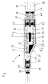
- the branch sleeve 1 shown as an example in the figure has an approximately T-shaped one Branch part 3, which is designed, for example, with three as a socket Plug devices 5 and 6 is provided.
- the two plug devices 5 are in this Embodiment in a line along the branch sleeve 1.
- the third connector 6 is parallel and offset to the two connectors 5 in an angled Area 7 of the branch part 3 is formed.
- the branch sleeve 1 shown here the especially suitable for single-line plastic or medium voltage cables, serves to establish an electrical connection between an electrical conductor 9 a main cable 11 and an electrical conductor 13 of a branch cable 15.
- the end of the electrical conductor 13 of the branch cable 15 is for example by means of a Figure shown insoluble pressing or by means of a screw with a provided electrical connector 17, the z. B. in the angled area 7 of the Branch part 3 provided connector 6 and inserted by means of a Branch part 3 arranged locking connection in its position opposite the branch part is set.
- the electrical contact between connector 17 and branch part 3 is e.g. B. by means of known contact elements arranged in the plug device 6 ensured.
- the main cable 11 is severed in the illustrated embodiment.
- E.g. likewise by means of an insoluble pressing shown in the figure or by means of a Screw connection is a plug connector 19 at each of the two ends of the main cable 11 or 21 mounted.
- the two connectors 19 and 21 are, for example, in one Line connectors 5 of the branch part 3 are inserted and are in their position fixed for example by means of a latching connection provided in the branch part.
- the Fixing the connectors 17, 19 and 21 ensures a safe electrical Contact to branch part 3 and via this between main cable 11 and branch cable 15.
- the branch part 3 is enclosed by a sleeve body 25 which extends over the Branch part 3 and the sections of the ends of the Main cable 11 and the branch cable 15 extends away.
- the sleeve body 25 is, for. B. designed as a prefabricated slide-on part made of an elastic material such as silicone, so that the sleeve body due to its high elasticity and diameter tolerances Diameter changes of main cable 11 and branch cable 15 due to load changes can easily record. But it is also possible to the sleeve body 25 as Form cold shrink part.
- the Socket body 25 of the exemplary embodiment includes a branch part 3, electrically conductive field control element 27 integrated.
- the sleeve body 25 also has three cable bushings 29 for passing the two ends of the main cable 11 and the end of the branch cable 15. In order to break down too strong Enabling field strength concentrations in the area of these cable ends are in the area the cable bushings 29 with the respective shield of the main cable 11 or Branch cable 15 connected, electrically conductive field control elements 33 intended.
- the field control elements 27 and 33 are also elastic and in the Socket body 25 firmly cast.
- a braided hose 37, the z. B. is made of copper, connects the electrical Screen 39 of the two ends of the main cable 11 with each other and with the electrical Shield 41 of the branch cable 15.
- the braided hose 37 z. B. by means of a Press connector 43 with the shield wires of the shield 39 of the main cable 11 and Shield wires of the shield 41 of the branch cable 15 connected.
- a screw connector instead of the press connector 43.
- On the other side of the branch sleeve 1 is the single end of the main cable 11 z. B. means a contact roll spring 45 connected to the braided hose 37.
- a sealing clip is arranged on both cable ends. But it is also possible at this point a so-called two-finger split shrink cap use.
Abstract
Description
Die Erfindung betrifft eine Abzweigmuffe für Energiekabel nach dem Oberbegriff des Patentanspruchs 1.The invention relates to a branch sleeve for power cables according to the preamble of Claim 1.
Für Energiekabel sind verschiedene Abzweigmuffen bekannt, die mittels eines Abzweigteils eine elektrische Verbindung zwischen einem elektrischen Leiter eines Hauptkabels und einem elektrischen Leiter eines Abzweigkabels herstellen. Solche Abzweigmuffen werden in der Regel aber nur in Niederspannungsnetzen montiert. Abzweige von kunststoffisolierten Mittel- oder Hochspannungskabeln werden dagegen in sogenannten Schaltanlagen vorgenommen. Dazu ist es erforderlich, das Hauptkabel von der Kabeltrasse zur Schaltanlage zu führen, dort den Abzweig beispielsweise zu einem Transformator oder einem anderen elektrischen Gerät herzustellen und von der Schaltanlage aus das Hauptkabel zur Kabeltrasse zurückzuführen.Various branch sleeves are known for power cables, which are made by means of a branch part an electrical connection between an electrical conductor of a main cable and produce an electrical conductor of a branch cable. Such branch sleeves will be usually only installed in low-voltage networks. Branches of plastic-insulated medium or high voltage cables, however, are in so-called Switchgear made. For this it is necessary to remove the main cable from the cable route to the switchgear, there the branch, for example to a transformer or another electrical device and the main cable from the switchgear back to the cable route.
Der Erfindung liegt daher das Problem zugrunde, eine Abzweigmuffe für Energiekabel zu schaffen, die sich auch für kunststoffisolierte Mittel- oder Hochspannungskabel eignet und die einfache und kostengünstige Herstellung eines Abzweiges ermöglicht.The invention is therefore based on the problem of a branch sleeve for power cables create that is also suitable for plastic insulated medium or high voltage cables and enables a branch to be produced simply and inexpensively.
Dieses Problem wird gemäß der Erfindung dadurch gelöst, daß der elektrische Leiter des Abzweigkabels mit einem Steckverbinder versehen und mittels einer Steckverbindung mit dem Abzweigteil verbunden ist.This problem is solved according to the invention in that the electrical conductor of the Provide the branch cable with a connector and with a plug connection the branch part is connected.
Die durch die Erfindung erzielbaren Vorteile bestehen insbesondere darin, daß sich mit Hilfe der Abzweigmuffe auch bei kunststoffisolierten Mittel- oder Hochspannungskabeln auf einfache und kostengünstige Art und Weise ein Abzweig von einem elektrischen Leiter eines Hauptkabels zu einem elektrischen Leiter eines Abzweigkabels herstellen läßt. Durch die Verwendung einer Steckverbindung für den elektrischen Anschluß des Abzweigkabels an das Abzweigteil ist die Abzweigmuffe zudem schnell und einfach montierbar. Dies gilt in besonderem Maße, wenn ein vorgefertigter Muffenkörper verwendet wird. Die erfindungsgemäße Abzweigmuffe ermöglicht es beispielsweise, ein Abzweigkabel von der in der Kabeltrasse eines Hauptkabels angeordneten Abzweigmuffe aus unmittelbar zu einem Transformator oder einem anderen elektrischen Gerät zu führen, ohne daß eine zusätzliche Schaltanlage oder eine andere zusätzliche Vorrichtung zur Herstellung des Abzweiges notwendig sind. Zudem wird eine geringere Kabellänge zur Herstellung des Abzweiges benötigt. Auf diese Weise werden die bei der Installation eines Mittelspannungs- oder Hochspannungsnetzes anfallenden Kosten deutlich reduziert.The advantages that can be achieved by the invention consist in particular in that Help of the branch sleeve also with plastic insulated medium or high voltage cables a branch from an electrical conductor in a simple and inexpensive manner a main cable to an electrical conductor of a branch cable. By the use of a plug connection for the electrical connection of the branch cable The branch sleeve can also be quickly and easily installed on the branch part. this applies especially when a prefabricated sleeve body is used. The branch sleeve according to the invention makes it possible, for example, a branch cable from the Branch sleeve arranged in the cable route of a main cable from directly to one Transformer or other electrical device without additional Switchgear or other additional device for the production of the branch are necessary. In addition, there is a shorter cable length for the production of the branch needed. This way, when installing a medium voltage or High-voltage network costs significantly reduced.
Durch die in den Unteransprüchen aufgeführten Merkmale sind vorteilhafte Weiterbildungen und Verbesserungen der Erfindung möglich.The features listed in the subclaims are advantageous Further developments and improvements of the invention are possible.
Von Vorteil ist es, wenn das Hauptkabel durchtrennt, die beiden Enden seines elektrischen Leiters jeweils mit einem Steckverbinder versehen und mittels einer Steckverbindung mit dem Abzweigteil verbunden sind, so daß die Abzweigmuffe besonders einfach, schnell und kostengünstig montiert werden kann.It is advantageous if the main cable cuts through the two ends of its electrical Each conductor provided with a connector and with a connector are connected to the branch part, so that the branch sleeve is particularly simple, fast and can be assembled inexpensively.
Für eine besonders platzsparende Ausbildung der Abzweigmuffe und einen möglichst geringen Umfang an erforderlichen Erdarbeiten ist es von Vorteil, wenn das Abzweigkabel parallel zu dem Hauptkabel aus dem Muffenkörper herausgeführt ist. Eine solche Form der Abzweigmuffe wird auch als Hosenform oder Parallelform bezeichnet.For a particularly space-saving design of the branch sleeve and one if possible small amount of earthwork required, it is advantageous if the branch cable is led out of the sleeve body parallel to the main cable. Such a form of Branch sleeve is also referred to as a pant shape or parallel shape.
Um zu verhindern, daß die Steckverbinder des Abzweigkabels und des Hauptkabels sich gegenüber dem Abzweigteil verschieben und im Extremfall aus dem Abzweigteil herausrutschen können und kein ausreichender elektrischer Kontakt zwischen den beiden Enden des Hauptkabels und dem Abzweigkabel sichergestellt ist, ist es von Vorteil, wenn die Steckverbinder in dem Abzweigteil in ihrer Lage fixiert sind.To prevent the connectors of the branch cable and the main cable move relative to the branch part and in extreme cases out of the branch part can slip out and there is insufficient electrical contact between the two Ends of the main cable and the branch cable is secured, it is advantageous if the connectors are fixed in their position in the branch part.
Für eine einfache und schnelle Montage des Muffenkörpers über dem Abzweigteil sowie ein dichtes und spaltfreies Anliegen des Muffenkörpers an den umschlossenen Flächen ist es von Vorteil, wenn der Muffenkörper als vorgefertigtes Aufschiebeteil aus einem elastischen Werkstoff ausgebildet ist. For simple and quick assembly of the socket body over the branch part as well as a it is tight and gap-free contact of the socket body on the enclosed surfaces of advantage if the sleeve body as a prefabricated slide-on part made of an elastic Material is formed.
Aus den gleichen Gründen ist es ebenfalls von Vorteil, wenn der Muffenkörper als Kaltschrumpfteil ausgebildet ist. Ein als Kaltschrumpfteil ausgebildeter Muffenkörper läßt sich für einen weiten Bereich verschieden großer Kabelquerschnitte verwenden. Zudem ermöglicht ein Kaltschrumpfteil einen besonders dichten Abschluß der Abzweigmuffe nach außen mit einer spaltfreien Umschließung der Enden des Abzweigkabels und des Hauptkabels.For the same reasons, it is also advantageous if the sleeve body as Cold shrink part is formed. A sleeve body designed as a cold shrink part use for a wide range of cable cross sections of different sizes. In addition A cold shrink part enables a particularly tight seal of the branch sleeve outside with a gap-free enclosure of the ends of the branch cable and the Main cable.
Um eine zu starke Konzentration der Feldstärke im Bereich der Enden des Hauptkabels und des Abzweigkabels sowie im Bereich des Abzweigteils zu vermeiden, ist es von Vorteil, wenn in dem Muffenkörper elektrisch leitfähige Feldsteuerelemente angeordnet sind. Dabei ist es besonders vorteilhaft, wenn das Abzweigteil von einem solchen elektrisch leitfähigen Feldsteuerelement umschlossen ist. Für einen einfachen Aufbau der Abzweigmuffe ist es von Vorteil, wenn die elektrisch leitfähigen Feldsteuerelemente in dem Muffenkörper integriert sind.To a too strong concentration of the field strength in the area of the ends of the main cable and of the branch cable and in the area of the branch part, it is advantageous to if electrically conductive field control elements are arranged in the sleeve body. Here it is particularly advantageous if the branch part of such an electrically conductive Field control is enclosed. It is for a simple structure of the branch sleeve advantageous if the electrically conductive field control elements in the sleeve body are integrated.
Um einen feuchtigkeitsdichten Abschluß der Abzweigmuffe zu gewährleisten, ist es vorteilhaft, wenn über dem Muffenkörper ein die Enden des Hauptkabels und des Abzweigkabels umschließender Schrumpfschlauch angeordnet ist.In order to ensure a moisture-tight closure of the branch sleeve, it is advantageous if the ends of the main cable and the Branch cable enclosing shrink tube is arranged.
Ein Ausführungsbeispiel der Erfindung ist in der Zeichnung vereinfacht dargestellt und in der nachfolgenden Beschreibung näher erläutert.An embodiment of the invention is shown in simplified form in the drawing and in the following description explained.
Die in der Figur beispielhaft dargestellte Abzweigmuffe 1 weist ein etwa T-förmiges
Abzweigteil 3 auf, das beispielsweise mit drei als Steckbuchse ausgebildeten
Steckvorrichtungen 5 und 6 versehen ist. Die beiden Steckvorrichtungen 5 liegen bei diesem
Ausführungsbeispiel in einer Linie längs der Abzweigmuffe 1. Die dritte Steckvorrichtung 6
ist parallel und dabei versetzt zu den beiden Steckvorrichtungen 5 in einem abgewinkelten
Bereich 7 des Abzweigteils 3 ausgebildet. Die hier dargestellte Abzweigmuffe 1, die sich
insbesondere für einadnge kunststoffisolierte Mittel- oder Hochspannungskabel eignet,
dient zur Herstellung einer elektrischen Verbindung zwischen einem elektrischen Leiter 9
eines Hauptkabels 11 und einem elektrischen Leiter 13 eines Abzweigkabels 15. Das Ende
des elektrischen Leiters 13 des Abzweigkabels 15 ist beispielsweise mittels einer in der
Figur dargestellten unlösbaren Verpressung oder mittels einer Verschraubung mit einem
elektrischen Steckverbinder 17 versehen, der z. B. in die im abgewinkelten Bereich 7 des
Abzweigteils 3 vorgesehene Steckvorrichtung 6 gesteckt und mittels einer in dem
Abzweigteil 3 angeordneten Rastverbindung in seiner Lage gegenüber dem Abzweigteil
festgelegt ist. Der elektrische Kontakt zwischen Steckverbinder 17 und Abzweigteil 3 wird
z. B. mittels in der Steckvorrichtung 6 angeordneter bekannter Kontaktelemente
sichergestellt.The branch sleeve 1 shown as an example in the figure has an approximately T-shaped one
Branch part 3, which is designed, for example, with three as a
Das Hauptkabel 11 ist bei dem dargestellten Ausführungsbeispiel durchtrennt. Z. B.
ebenfalls mittels einer in der Figur dargestellten unlösbaren Verpressung oder mittels einer
Verschraubung ist an jedem der beiden Enden des Hauptkabels 11 ein Steckverbinder 19
bzw. 21 montiert. Die beiden Steckverbinder 19 und 21 sind beispielsweise in die in einer
Linie liegenden Steckvorrichtungen 5 des Abzweigteils 3 gesteckt und werden in ihrer Lage
beispielsweise mittels einer in dem Abzweigteil vorgesehenen Rastverbindung fixiert. Die
Fixierung der Steckverbinder 17, 19 und 21 gewährleistet einen sicheren elektrischen
Kontakt zu dem Abzweigteil 3 und über dieses zwischen Hauptkabel 11 und Abzweigkabel
15. In den Steckvorrichtungen 5 sind z. B. ebenfalls bekannte Kontaktelemente angeordnet,
die einen sicheren elektrischen Kontakt zwischen den beiden Steckverbindern 19 und 21
und dem Abzweigteil 3 gewährleisten.The
Das Abzweigteil 3 ist von einem Muffenkörper 25 umschlossen, der sich über das
Abzweigteil 3 und die bis auf die Isolierung abgesetzten Abschnitte der Enden des
Hauptkabels 11 und des Abzweigkabels 15 hinweg erstreckt. Der Muffenkörper 25 ist z. B.
als vorgefertigtes Aufschiebeteil aus einem elastischen Werkstoff wie Silikon ausgebildet,
so daß der Muffenkörper durch seine hohe Elastizität Durchmessertoleranzen und durch
Lastwechsel bedingte Durchmesseränderungen von Hauptkabel 11 und Abzweigkabel 15
problemlos aufnehmen kann. Es ist aber ebenfalls möglich, den Muffenkörper 25 als
Kaltschrumpfteil auszubilden. Zur Feldsteuerung im Bereich des Abzweigteils 3 ist in dem
Muffenkörper 25 des Ausfükrungsbeispiels ein das Abzweigteil 3 umschließendes,
elektrisch leitfähiges Feldsteuerelement 27 integriert. Der Muffenkörper 25 weist zudem
drei Kabeldurchführungen 29 zum Hindurchführen der beiden Enden des Hauptkabels 11
und des Endes des Abzweigkabels 15 auf. Um auch den Abbau von zu starken
Feldstärkekonzentrationen im Bereich dieser Kabelenden zu ermöglichen, sind im Bereich
der Kabeldurchführungen 29 mit dem jeweiligen Schirm des Hauptkabels 11 bzw.
Abzweigkabels 15 in Verbindung stehende, elektrisch leitfähige Feldsteuerelemente 33
vorgesehen. Die Feldsteuerelemente 27 und 33 sind ebenfalls elastisch und in dem
Muffenkörper 25 fest eingegossen. The branch part 3 is enclosed by a sleeve body 25 which extends over the
Branch part 3 and the sections of the ends of the
Ein Geflechtschlauch 37, der z. B. aus Kupfer ausgebildet ist, verbindet den elektrischen
Schirm 39 der beiden Enden des Hauptkabels 11 miteinander sowie mit dem elektrischen
Schirm 41 des Abzweigkabels 15. An dem Ende der Abzweigmuffe 1, an dem das eine Ende
des Hauptkabels 11 und das Ende des Abzweigkabels 15 parallel zueinander aus dem
Muffenkörper 25 herausgeführt werden, ist der Geflechtschlauch 37 z. B. mittels eines
Preßverbinders 43 mit den Schirmdrähten des Schirms 39 des Hauptkabels 11 und den
Schirmdrähten des Schirms 41 des Abzweigkabels 15 verbunden. Es ist aber ebenfalls
möglich, anstelle des Preßverbinders 43 einen Schraubverbinder zu verwenden. Auf der
anderen Seite der Abzweigmuffe 1 ist das einzelne Ende des Hauptkabels 11 z. B. mittels
einer Kontaktrollfeder 45 mit dem Geflechtschlauch 37 verbunden.A
Über dem Geflechtschlauch 37 ist ein Schrumpfschlauch 49 auf die Abzweigmuffe 1 z. B.
durch Warmschrumpfen aufgeschrumpft und überdeckt den Geflechtschlauch 37 sowie die
Enden des Hauptkabels 11 und des Abzweigkabels 15. Durch das Aufschrumpfen schafft
der Schrumpfschlauch 49 einen feuchtigkeitsdichten Abschluß der Abzweigmuffe 1, so daß
der Eintritt von Feuchtigkeit in das Innere der Abzweigmuffe 1 verhindert wird. An dem
Ende der Abzweigmuffe 1, an dem sowohl ein Ende des Hauptkabels 11 als auch das Ende
des Abzweigkabels 15 aus der Abzweigmuffe 1 herausgeführt werden, ist zwischen den
beiden Kabelenden beispielsweise eine Dichtklammer angeordnet. Es ist aber ebenfalls
möglich, an dieser Stelle eine sogenannte Zwei-Finger-Aufteilungsschrumpfkappe zu
verwenden.About the
Claims (10)
Applications Claiming Priority (2)
| Application Number | Priority Date | Filing Date | Title |
|---|---|---|---|
| DE19733853 | 1997-08-05 | ||
| DE19733853A DE19733853A1 (en) | 1997-08-05 | 1997-08-05 | Branch sleeve for electrical cables |
Publications (2)
| Publication Number | Publication Date |
|---|---|
| EP0896409A2 true EP0896409A2 (en) | 1999-02-10 |
| EP0896409A3 EP0896409A3 (en) | 1999-12-15 |
Family
ID=7838056
Family Applications (1)
| Application Number | Title | Priority Date | Filing Date |
|---|---|---|---|
| EP98401776A Withdrawn EP0896409A3 (en) | 1997-08-05 | 1998-07-13 | Branching joint for power cable |
Country Status (2)
| Country | Link |
|---|---|
| EP (1) | EP0896409A3 (en) |
| DE (1) | DE19733853A1 (en) |
Cited By (3)
| Publication number | Priority date | Publication date | Assignee | Title |
|---|---|---|---|---|
| WO2014070851A1 (en) | 2012-10-31 | 2014-05-08 | Delphi Technologies, Inc. | Device and method for splicing shielded wire cables |
| US10756529B2 (en) | 2016-10-14 | 2020-08-25 | Supergrid Institute | Underwater electrical connection system |
| EP4049898A1 (en) * | 2021-02-25 | 2022-08-31 | LEONI Bordnetz-Systeme GmbH | Cable set and method for configuring a cable set |
Families Citing this family (2)
| Publication number | Priority date | Publication date | Assignee | Title |
|---|---|---|---|---|
| DE102013011874A1 (en) | 2013-07-17 | 2015-01-22 | Leoni Bordnetz-Systeme Gmbh | Electric power distributor for an electric or hybrid vehicle and distributor housing for such a power distributor |
| DE102014008536A1 (en) * | 2014-06-16 | 2015-12-17 | Rwe Deutschland Ag | Electric house connection line |
Citations (8)
| Publication number | Priority date | Publication date | Assignee | Title |
|---|---|---|---|---|
| DE3508329A1 (en) * | 1985-03-06 | 1986-09-11 | Siemens AG, 1000 Berlin und 8000 München | Plug-in cable fitting |
| WO1990013933A1 (en) * | 1989-05-03 | 1990-11-15 | Nkf Kabel B.V. | Plug-in connection for high-voltage plastic cables |
| JPH05219638A (en) * | 1992-02-05 | 1993-08-27 | Reiji Nakamura | Branch joint for high voltage wire |
| JPH05244715A (en) * | 1992-02-26 | 1993-09-21 | Showa Electric Wire & Cable Co Ltd | Cable branch joint |
| WO1994016485A1 (en) * | 1993-01-15 | 1994-07-21 | Raychem Gmbh | Cable joint |
| JPH06327133A (en) * | 1993-05-14 | 1994-11-25 | Showa Electric Wire & Cable Co Ltd | Branch joint |
| JPH07153319A (en) * | 1993-11-29 | 1995-06-16 | Hitachi Cable Ltd | Branch part-attached cable |
| JPH0865874A (en) * | 1994-08-15 | 1996-03-08 | Hitachi Cable Ltd | High-voltage fire-resistant cable connection part |
Family Cites Families (4)
| Publication number | Priority date | Publication date | Assignee | Title |
|---|---|---|---|---|
| DE3308225A1 (en) * | 1983-03-04 | 1984-09-06 | Siemens AG, 1000 Berlin und 8000 München | Prefabricated connecting sleeve with a conductor plug connection |
| DE8804221U1 (en) * | 1988-03-29 | 1988-05-11 | Felten & Guilleaume Energietechnik Ag, 5000 Koeln, De | |
| DE9217344U1 (en) * | 1992-12-18 | 1993-02-18 | Mannesmann Kienzle Gmbh, 7730 Villingen-Schwenningen, De | |
| DE9300775U1 (en) * | 1993-01-21 | 1993-04-22 | August Rich. Dietz U. Sohn Draht- Und Hanfseilwerk Gmbh & Co. Kg, 8632 Neustadt, De |
-
1997
- 1997-08-05 DE DE19733853A patent/DE19733853A1/en not_active Withdrawn
-
1998
- 1998-07-13 EP EP98401776A patent/EP0896409A3/en not_active Withdrawn
Patent Citations (8)
| Publication number | Priority date | Publication date | Assignee | Title |
|---|---|---|---|---|
| DE3508329A1 (en) * | 1985-03-06 | 1986-09-11 | Siemens AG, 1000 Berlin und 8000 München | Plug-in cable fitting |
| WO1990013933A1 (en) * | 1989-05-03 | 1990-11-15 | Nkf Kabel B.V. | Plug-in connection for high-voltage plastic cables |
| JPH05219638A (en) * | 1992-02-05 | 1993-08-27 | Reiji Nakamura | Branch joint for high voltage wire |
| JPH05244715A (en) * | 1992-02-26 | 1993-09-21 | Showa Electric Wire & Cable Co Ltd | Cable branch joint |
| WO1994016485A1 (en) * | 1993-01-15 | 1994-07-21 | Raychem Gmbh | Cable joint |
| JPH06327133A (en) * | 1993-05-14 | 1994-11-25 | Showa Electric Wire & Cable Co Ltd | Branch joint |
| JPH07153319A (en) * | 1993-11-29 | 1995-06-16 | Hitachi Cable Ltd | Branch part-attached cable |
| JPH0865874A (en) * | 1994-08-15 | 1996-03-08 | Hitachi Cable Ltd | High-voltage fire-resistant cable connection part |
Non-Patent Citations (5)
| Title |
|---|
| PATENT ABSTRACTS OF JAPAN vol. 17, no. 668 (E-1473), 9. Dezember 1993 (1993-12-09) & JP 05 219638 A (REIJI NAKAMURA), 27. August 1993 (1993-08-27) * |
| PATENT ABSTRACTS OF JAPAN vol. 18, no. 3 (E-1485), 6. Januar 1994 (1994-01-06) & JP 05 244715 A (SHOWA ELECTRIC WIRE & CABLE), 21. September 1993 (1993-09-21) * |
| PATENT ABSTRACTS OF JAPAN vol. 95, no. 2, 31. März 1995 (1995-03-31) & JP 06 327133 A (SHOWA ELECTRIC WIRE & CABLE), 25. November 1994 (1994-11-25) * |
| PATENT ABSTRACTS OF JAPAN vol. 95, no. 9, 31. Oktober 1995 (1995-10-31) & JP 07 153319 A (HITACHI CABLE), 16. Juni 1995 (1995-06-16) * |
| PATENT ABSTRACTS OF JAPAN vol. 96, no. 7, 31. Juli 1996 (1996-07-31) & JP 08 065874 A (HITACHI CABLE), 8. März 1996 (1996-03-08) * |
Cited By (5)
| Publication number | Priority date | Publication date | Assignee | Title |
|---|---|---|---|---|
| WO2014070851A1 (en) | 2012-10-31 | 2014-05-08 | Delphi Technologies, Inc. | Device and method for splicing shielded wire cables |
| EP2915171A4 (en) * | 2012-10-31 | 2016-07-13 | Delphi Tech Inc | Device and method for splicing shielded wire cables |
| US9917434B2 (en) | 2012-10-31 | 2018-03-13 | Delphi Technologies, Inc. | Device and method for splicing shielded wire cables |
| US10756529B2 (en) | 2016-10-14 | 2020-08-25 | Supergrid Institute | Underwater electrical connection system |
| EP4049898A1 (en) * | 2021-02-25 | 2022-08-31 | LEONI Bordnetz-Systeme GmbH | Cable set and method for configuring a cable set |
Also Published As
| Publication number | Publication date |
|---|---|
| DE19733853A1 (en) | 1999-02-11 |
| EP0896409A3 (en) | 1999-12-15 |
Similar Documents
| Publication | Publication Date | Title |
|---|---|---|
| EP3454427A1 (en) | Connection kit, installation kit and electric installation | |
| DE2119804C2 (en) | Method of establishing a cable connection | |
| DE2132418C2 (en) | Cable connector for high voltage cables | |
| EP3685471B1 (en) | High-current connector comprising an insulating bush | |
| EP0691721B1 (en) | Connector termination | |
| DE3301362A1 (en) | CABLE DISTRIBUTOR, OR - TAP | |
| DE1765120A1 (en) | Connection piece for electrical conductors | |
| DE19539184C2 (en) | Contact element for generating an electrical contact between the main conductor and branch conductor, and a connecting terminal with this contact element | |
| DE102013016099B4 (en) | Multiple connection cable for connecting high-voltage devices of a motor vehicle and motor vehicle | |
| EP0896409A2 (en) | Branching joint for power cable | |
| DE102007013332B4 (en) | Device for forming a sheath, in particular for a connection point between two shielded cables and cable arrangement with such cables | |
| DE3042595C2 (en) | Slide-on connection sleeve with split insulating body for plastic-insulated medium-voltage cables | |
| DE19945148A1 (en) | End closure unit for high-voltage electric cables comprises a socket which in the insulator body is at least partially embedded in a solid insulating element and has an opening for entry of the cable plug | |
| DE4108901C2 (en) | Device for connecting and connecting an electrical line | |
| EP0773601A2 (en) | Pluggable security connection | |
| DE10022547C2 (en) | Cable connection or connection device | |
| DE4403571C1 (en) | Coupling for plastic insulated high voltage cables has screw terminal block within housing that has inner and outer sections of that shrouds connection. | |
| DE19845006C1 (en) | Overhead cable connector for MV electrical network cables has corresponding cable wire ends enclosed by common connector and field control body contained within outer insulator | |
| DE3914978A1 (en) | Optical waveguide coupler and multiphase electric connector interface - incorporates pilot plug and socket with light-guides on axis of symmetry of standard electric connector parts | |
| DE3210223C2 (en) | Knee-shaped, pluggable cable set | |
| DE3247482A1 (en) | Connecting device | |
| DE3301361A1 (en) | CABLE DISTRIBUTOR, OR - TAP | |
| DE3304145C2 (en) | Cable termination or connection | |
| EP0285079A2 (en) | Clamping device to realize a tapping on a tension cable conductor and manufacture of such a tapping | |
| DE19539060A1 (en) | High-voltage, high-performance fuse for an electrical connection line |
Legal Events
| Date | Code | Title | Description |
|---|---|---|---|
| PUAI | Public reference made under article 153(3) epc to a published international application that has entered the european phase |
Free format text: ORIGINAL CODE: 0009012 |
|
| AK | Designated contracting states |
Kind code of ref document: A2 Designated state(s): AT BE CH DE ES FR GB IT LI NL SE |
|
| AX | Request for extension of the european patent |
Free format text: AL;LT;LV;MK;RO;SI |
|
| PUAL | Search report despatched |
Free format text: ORIGINAL CODE: 0009013 |
|
| AK | Designated contracting states |
Kind code of ref document: A3 Designated state(s): AT BE CH CY DE DK ES FI FR GB GR IE IT LI LU MC NL PT SE |
|
| AX | Request for extension of the european patent |
Free format text: AL;LT;LV;MK;RO;SI |
|
| 17P | Request for examination filed |
Effective date: 19991113 |
|
| 17Q | First examination report despatched |
Effective date: 20000313 |
|
| AKX | Designation fees paid | ||
| REG | Reference to a national code |
Ref country code: DE Ref legal event code: 8566 |
|
| RBV | Designated contracting states (corrected) |
Designated state(s): AT BE CH DE ES FR GB IT LI NL SE |
|
| RAP1 | Party data changed (applicant data changed or rights of an application transferred) |
Owner name: NEXANS |
|
| STAA | Information on the status of an ep patent application or granted ep patent |
Free format text: STATUS: THE APPLICATION IS DEEMED TO BE WITHDRAWN |
|
| 18D | Application deemed to be withdrawn |
Effective date: 20010717 |