EP3336675B1 - Dispositifs électroniques et procédé d'entrée de dispositif électronique - Google Patents
Dispositifs électroniques et procédé d'entrée de dispositif électronique Download PDFInfo
- Publication number
- EP3336675B1 EP3336675B1 EP16835461.1A EP16835461A EP3336675B1 EP 3336675 B1 EP3336675 B1 EP 3336675B1 EP 16835461 A EP16835461 A EP 16835461A EP 3336675 B1 EP3336675 B1 EP 3336675B1
- Authority
- EP
- European Patent Office
- Prior art keywords
- area
- brush
- electronic device
- processor
- touch
- Prior art date
- Legal status (The legal status is an assumption and is not a legal conclusion. Google has not performed a legal analysis and makes no representation as to the accuracy of the status listed.)
- Active
Links
Images


Classifications
-
- G—PHYSICS
- G06—COMPUTING; CALCULATING OR COUNTING
- G06F—ELECTRIC DIGITAL DATA PROCESSING
- G06F3/00—Input arrangements for transferring data to be processed into a form capable of being handled by the computer; Output arrangements for transferring data from processing unit to output unit, e.g. interface arrangements
- G06F3/01—Input arrangements or combined input and output arrangements for interaction between user and computer
- G06F3/03—Arrangements for converting the position or the displacement of a member into a coded form
- G06F3/041—Digitisers, e.g. for touch screens or touch pads, characterised by the transducing means
- G06F3/0416—Control or interface arrangements specially adapted for digitisers
-
- G—PHYSICS
- G06—COMPUTING; CALCULATING OR COUNTING
- G06F—ELECTRIC DIGITAL DATA PROCESSING
- G06F3/00—Input arrangements for transferring data to be processed into a form capable of being handled by the computer; Output arrangements for transferring data from processing unit to output unit, e.g. interface arrangements
- G06F3/01—Input arrangements or combined input and output arrangements for interaction between user and computer
- G06F3/017—Gesture based interaction, e.g. based on a set of recognized hand gestures
-
- G—PHYSICS
- G06—COMPUTING; CALCULATING OR COUNTING
- G06F—ELECTRIC DIGITAL DATA PROCESSING
- G06F3/00—Input arrangements for transferring data to be processed into a form capable of being handled by the computer; Output arrangements for transferring data from processing unit to output unit, e.g. interface arrangements
- G06F3/01—Input arrangements or combined input and output arrangements for interaction between user and computer
- G06F3/03—Arrangements for converting the position or the displacement of a member into a coded form
- G06F3/033—Pointing devices displaced or positioned by the user, e.g. mice, trackballs, pens or joysticks; Accessories therefor
- G06F3/0354—Pointing devices displaced or positioned by the user, e.g. mice, trackballs, pens or joysticks; Accessories therefor with detection of 2D relative movements between the device, or an operating part thereof, and a plane or surface, e.g. 2D mice, trackballs, pens or pucks
- G06F3/03545—Pens or stylus
-
- G—PHYSICS
- G06—COMPUTING; CALCULATING OR COUNTING
- G06F—ELECTRIC DIGITAL DATA PROCESSING
- G06F3/00—Input arrangements for transferring data to be processed into a form capable of being handled by the computer; Output arrangements for transferring data from processing unit to output unit, e.g. interface arrangements
- G06F3/01—Input arrangements or combined input and output arrangements for interaction between user and computer
- G06F3/03—Arrangements for converting the position or the displacement of a member into a coded form
- G06F3/041—Digitisers, e.g. for touch screens or touch pads, characterised by the transducing means
- G06F3/0412—Digitisers structurally integrated in a display
-
- G—PHYSICS
- G06—COMPUTING; CALCULATING OR COUNTING
- G06F—ELECTRIC DIGITAL DATA PROCESSING
- G06F3/00—Input arrangements for transferring data to be processed into a form capable of being handled by the computer; Output arrangements for transferring data from processing unit to output unit, e.g. interface arrangements
- G06F3/01—Input arrangements or combined input and output arrangements for interaction between user and computer
- G06F3/048—Interaction techniques based on graphical user interfaces [GUI]
- G06F3/0487—Interaction techniques based on graphical user interfaces [GUI] using specific features provided by the input device, e.g. functions controlled by the rotation of a mouse with dual sensing arrangements, or of the nature of the input device, e.g. tap gestures based on pressure sensed by a digitiser
- G06F3/0488—Interaction techniques based on graphical user interfaces [GUI] using specific features provided by the input device, e.g. functions controlled by the rotation of a mouse with dual sensing arrangements, or of the nature of the input device, e.g. tap gestures based on pressure sensed by a digitiser using a touch-screen or digitiser, e.g. input of commands through traced gestures
- G06F3/04883—Interaction techniques based on graphical user interfaces [GUI] using specific features provided by the input device, e.g. functions controlled by the rotation of a mouse with dual sensing arrangements, or of the nature of the input device, e.g. tap gestures based on pressure sensed by a digitiser using a touch-screen or digitiser, e.g. input of commands through traced gestures for inputting data by handwriting, e.g. gesture or text
Definitions
- Various embodiments relate to an electronic device and an input method of an electronic device.
- a user input interface such as a touch panel
- a user input interface enables users to provide intuitive input to electronic devices as if writing on a notebook.
- a stylus pen which is currently used, may be employed to provide various drawing input to an electronic device, in which the electronic device may output a drawing display on a display panel corresponding to a drawing input.
- the method of US 2014/362046 A1 detects a hand-placing region on a basis of strengths of capacitance signals, each strength being indicative of a change in capacitance and replaces values of capacitance signals corresponding to respective capacitors provided in the detected hand-placing region with a nil value indicative of a state where not touch input is made.
- WO 2013/013225 A1 discloses determining a magnitude of a detected input of a touch-screen portion of the touch-screen device, and an area of the detected input of the touch-screen portion; and modifying a graphical representation of the detected input based on the area and magnitude of the detected input.
- US 2013/120281 A1 discloses determining whether the stylus and/or the user touches the tablet input device, and if so, collecting touch position and/or pressure data from the tablet input device for the stylus and/or the user touch during the gesture.
- KR 2006 0084945 A discloses determining the thickness, shape, and concentration of a brush according to an object movement trajectory, and generating and displaying a brush-touch image corresponding to the determined thickness, shape, and concentration.
- An electronic device may be provided with a stylus pen or a stylus brush as an input device of the electronic device by the manufacturer of the electronic device. Since the stylus brush has the same apparent shape as a general brush, using the stylus brush as an input device of an electronic device enables a user to feel as if she/he were performing drawing input into the electronic device using an actual brush. However, the stylus brush resembles a general brush only from the aspects of shape and appearance, and performs input operation in the same manner as a stylus pen.
- an input device such as the stylus brush
- an input device such as the stylus brush
- Various embodiments of the present disclosure may provide an electronic device and an input method of an electronic device capable of providing drawing output corresponding to an input device, which is similar to that from an actual writing material, depending on the type of the input device that touches or approaches the electronic device.
- An electronic device and an input method of an electronic device may provide a drawing output corresponding to an input device, which is similar to that from an actual writing material, depending on the type of the input device that touches or approaches the electronic device, thereby providing user convenience.
- the expression “have”, “may have”, “include”, or “may include” refers to the existence of a corresponding feature (e.g., numeral, function, operation, or constituent element such as component), and does not exclude one or more additional features.
- the expression “A or B”, “at least one of A or/and B”, or “one or more of A or/and B” may include all possible combinations of the items listed.
- the expression “A or B”, “at least one of A and B”, or “at least one of A or B” refers to all of (1) including at least one A, (2) including at least one B, or (3) including all of at least one A and at least one B.
- a first”, “a second”, “the first”, or “the second” used in various embodiments of the present disclosure may modify various components regardless of the order and/or the importance but does not limit the corresponding components.
- a first user device and a second user device indicate different user devices although both of them are user devices.
- a first element may be termed a second element, and similarly, a second element may be termed a first element without departing from the scope of the present disclosure.
- first element when an element (e.g., first element) is referred to as being (operatively or communicatively) "connected,” or “coupled,” to another element (e.g., second element), it may be directly connected or coupled directly to the other element or any other element (e.g., third element) may be interposer between them.
- first element when an element (e.g., first element) is referred to as being “directly connected,” or “directly coupled” to another element (second element), there are no element (e.g., third element) interposed between them.
- processor adapted (or configured) to perform A, B, and C may mean a dedicated processor (e.g., embedded processor) only for performing the corresponding operations or a generic-purpose processor (e.g., Central Processing Unit (CPU) or Application Processor (AP)) that can perform the corresponding operations by executing one or more software programs stored in a memory device.
- processor e.g., embedded processor
- generic-purpose processor e.g., Central Processing Unit (CPU) or Application Processor (AP)
- An electronic device may include at least one of, for example, a smart phone, a tablet Personal Computer (PC), a mobile phone, a video phone, an electronic book reader (e-book reader), a desktop PC, a laptop PC, a netbook computer, a workstation, a server, a Personal Digital Assistant (PDA), a Portable Multimedia Player (PMP), a MPEG-1 audio layer-3 (MP3) player, a mobile medical device, a camera, and a wearable device.
- a smart phone a tablet Personal Computer (PC), a mobile phone, a video phone, an electronic book reader (e-book reader), a desktop PC, a laptop PC, a netbook computer, a workstation, a server, a Personal Digital Assistant (PDA), a Portable Multimedia Player (PMP), a MPEG-1 audio layer-3 (MP3) player, a mobile medical device, a camera, and a wearable device.
- PC Personal Computer
- PMP Portable Multimedia Player
- MP3 MPEG-1 audio layer-3
- the wearable device may include at least one of an accessory type (e.g., a watch, a ring, a bracelet, an anklet, a necklace, a glasses, a contact lens, or a Head-Mounted Device (HMD)), a fabric or clothing integrated type (e.g., an electronic clothing), a body-mounted type (e.g., a skin pad, or tattoo), and a bio-implantable type (e.g., an implantable circuit).
- an accessory type e.g., a watch, a ring, a bracelet, an anklet, a necklace, a glasses, a contact lens, or a Head-Mounted Device (HMD)
- a fabric or clothing integrated type e.g., an electronic clothing
- a body-mounted type e.g., a skin pad, or tattoo
- a bio-implantable type e.g., an implantable circuit
- the electronic device may be a home appliance.
- the home appliance may include at least one of, for example, a television, a Digital Video Disk (DVD) player, an audio, a refrigerator, an air conditioner, a vacuum cleaner, an oven, a microwave oven, a washing machine, an air cleaner, a set-top box, a home automation control panel, a security control panel, a TV box (e.g., Samsung HomeSyncTM, Apple TVTM, or Google TVTM), a game console (e.g., XboxTM and PlayStationTM), an electronic dictionary, an electronic key, a camcorder, and an electronic photo frame.
- DVD Digital Video Disk
- the electronic device may include at least one of various medical devices (e.g., various portable medical measuring devices (a blood glucose monitoring device, a heart rate monitoring device, a blood pressure measuring device, a body temperature measuring device, etc.), a Magnetic Resonance Angiography (MRA), a Magnetic Resonance Imaging (MRI), a Computed Tomography (CT) machine, and an ultrasonic machine), a navigation device, a Global Positioning System (GPS) receiver, an Event Data Recorder (EDR), a Flight Data Recorder (FDR), a Vehicle Infotainment Devices, an electronic devices for a ship (e.g., a navigation device for a ship, and a gyro-compass), avionics, security devices, an automotive head unit, a robot for home or industry, an Automatic Teller's Machine (ATM) in banks, Point Of Sales (POS) in a shop, or internet device of things (e.g., a light bulb, various sensors, electric or gas meter, or a light bulb
- the electronic device may include at least one of a part of furniture or a building/structure, an electronic board, an electronic signature receiving device, a projector, and various kinds of measuring instruments (e.g., a water meter, an electric meter, a gas meter, and a radio wave meter).
- the electronic device may be a combination of one or more of the aforementioned various devices.
- the electronic device may also be a flexible device.
- the electronic device according to an embodiment of the present disclosure is not limited to the aforementioned devices, and may include a new electronic device according to the development of technology.
- the term "user” may indicate a person using an electronic device or a device (e.g., an artificial intelligence electronic device) using an electronic device.
- FIG. 1 illustrates an electronic device 101 in a network environment 100 according to various embodiments.
- the electronic device 101 may include a bus 110, a processor 120, a memory 130, an input/output interface 150, a display 160, and a communication interface 170.
- at least one of the components may be omitted, or additional components may be further included in the electronic device 101.
- the bus 110 may include, for example, a circuit that connects the components 110 to 170 to each other and delivers communications (for example, control messages and/or data) between the components.
- the processor 120 may include one or more of a Central Processing Unit (CPU), an Application Processor (AP), and a Communication Processor (CP).
- the processor 120 may control, for example, at least one different component of the electronic device 101, and/or may perform an operation relating to communication or data processing.
- the memory 130 may include a volatile and/or nonvolatile memory.
- the memory 130 may store, for example, a command or data related to at least one different component of the electronic device 101.
- the memory 130 may store software and/or a program 140.
- the program 140 may include, for example, a kernel 141, middleware 143, an Application Programming Interface (API) 145, and/or an application program (or "application”) 147.
- At least part of the kernel 141, the middleware 143, and the API 145 may be designated as an Operating System (OS).
- OS Operating System
- the kernel 141 may control or manage system resources (for example, the bus 110, the processor 120, the memory 130, or the like) used to perform an operation or function implemented in other programs (for example, the middleware 143, the API 145, or the application 147). Further, the kernel 141 may provide an interface that allows the middleware 143, the API 145, or the application 147 to access individual components of the electronic device 101 to thereby control or manage system resources.
- system resources for example, the bus 110, the processor 120, the memory 130, or the like
- the kernel 141 may provide an interface that allows the middleware 143, the API 145, or the application 147 to access individual components of the electronic device 101 to thereby control or manage system resources.
- the middleware 143 may serve as a relay so that, for example, the API 145 or the application 147 communicates with the kernel 141 to exchange data.
- the middleware 143 may process one or more requests for operations received from the application 147 according to the priority thereof. For example, the middleware 143 may assign at least one application 147 a priority for using a system resource (for example, the bus 110, the processor 120, the memory 130, or the like) of the electronic device 101. For example, the middleware 143 may process the one or more requests for operations according to the priority assigned to the at least one application, thereby performing scheduling or load balancing for the one or more requests for operations.
- a system resource for example, the bus 110, the processor 120, the memory 130, or the like
- the API 145 is, for example, an interface for the application 147 to control a function provided from the kernel 141 or the middleware 143, and may include, for example, at least one interface or function (for example, a command) for file control, window control, image processing, or text control.
- the input/output interface 150 may serve as an interface that delivers a command or data, which is input from, for example, a user or a different external device, to a different component(s) of the electronic device 101. Further, the input/output interface 150 may output a command or data, which is received from a different component(s) of the electronic device 101, to the user or to the different external device.
- the display 160 may include, for example, a Liquid Crystal Display (LCD), a Light-Emitting Diode (LED) display, an Organic Light-Emitting Diode (OLED) display, a Micro-Electro-Mechanical Systems (MEMS) display, or an electronic paper display.
- the display 160 may display, for example, various types of content (for example, text, an image, a video, an icon, a symbol, or the like) for the user.
- the display 160 may include a touch screen and may receive touch, gesture, proximity, or hovering input using, for example, an electronic pen or a body part of a user.
- the communication interface 170 may establish communication, for example, between the electronic device 101 and an external device (for example, a first external electronic device 102, a second external electronic device 104, or a server 106).
- the communication interface 170 may be connected to a network 162 via wireless communication or wire-based communication to communicate with the external device (for example, the second external electronic device 104 or the server 106).
- the wireless communication may use, for example, a cellular communication protocol, which may be, for example, at least one of Long-Term Evolution (LTE), LTE-Advanced (LTE-A), Code Division Multiple Access (CDMA), Wideband CDMA (WCDMA), Universal Mobile Telecommunications System (UMTS), Wireless Broadband (WiBro), and Global System for Mobile Communications (GSM).
- LTE Long-Term Evolution
- LTE-A Long-Term Evolution
- CDMA Code Division Multiple Access
- WCDMA Wideband CDMA
- UMTS Universal Mobile Telecommunications System
- WiBro Wireless Broadband
- GSM Global System for Mobile Communications
- the wireless communication may include, for example, short-range communication 164.
- the short-range communication 164 may include, for example, at least one of Wireless Fidelity (Wi-Fi), Bluetooth, Near-Field Communication (NFC), and Global Navigation Satellite System (GNSS).
- Wi-Fi Wireless Fidelity
- NFC Near-Field Communication
- GNSS Global Navigation Satellite System
- the GNSS may include, for example, at least one of a Global Positioning System (GPS), a Global Navigation Satellite System (GLONASS), a BeiDou Navigation Satellite System (hereinafter, "BeiDou”), and Galileo, which is the European global satellite-based navigation system, depending on a use area or bandwidth.
- GPS Global Positioning System
- GLONASS Global Navigation Satellite System
- BeiDou BeiDou Navigation Satellite System
- Galileo Galileo
- the wire-based communication may include, for example, at least one of Universal Serial Bus (USB), High-Definition Multimedia Interface (HDMI), Recommended Standard 232 (RS-232), and Plain Old Telephone Service (POTS).
- the network 162 may include a telecommunications network, which may be, for example, at least one of a computer network (for example, a Local Area Network (LAN) or Wide Area Network (WAN)), the Internet, and a telephone network.
- LAN Local Area Network
- WAN Wide Area Network
- POTS Plain Old Telephone Service
- the first and second external electronic devices 102 and 104 may each be a device of a type that is the same as, or different from, that of the electronic device 101.
- the server 106 may include a group of one or more servers.
- all or some of the operations performed in the electronic device 101 may be performed in another electronic device or a plurality of electronic devices (for example, the electronic devices 102 and 104 or the server 106).
- the electronic device 101 may request another electronic device (for example, the electronic device 102 or 104, or the server 106) to perform at least some functions related to the function or service, instead of, or in addition to, autonomously performing the function or service.
- the other electronic device may perform the requested functions or additional functions and may transmit the result thereof to the electronic device 101.
- the electronic device 101 may provide the requested function or service using the same received result or by additionally processing the result.
- cloud-computing, distributed-computing, or client-server-computing technologies may be used.
- FIG. 2 is a block diagram of an electronic device 201 according to various embodiments.
- the electronic device 201 may include, for example, all or part of the electronic device 101 illustrated in FIG. 1 .
- the electronic device 201 may include one or more processors (for example, Application Processors (APs)) 210, a communication module 220, a Subscriber Identification Module (SIM) 224, a memory 230, a sensor module 240, an input device 250, a display 260, an interface 270, an audio module 280, a camera module 291, a power management module 295, a battery 296, an indicator 297, and a motor 298.
- APs Application Processors
- SIM Subscriber Identification Module
- the processors 210 may run, for example, an operating system or an application to control a plurality of hardware or software components that are connected to the processors 210, and may perform various kinds of data processing and operations.
- the processors 210 may be configured, for example, as a System on Chip (SoC).
- SoC System on Chip
- the processors 210 may further include a Graphic Processing Unit (GPU) and/or an image signal processor.
- the processors 210 may include at least part (for example, a cellular module 221) of the components illustrated in FIG. 2 .
- the processors 210 may load a command or data received from at least one of other components (for example, nonvolatile memory) into volatile memory to process the command or data, and may store various types of data in the nonvolatile memory.
- the communication module 220 may have a configuration that is the same as, or similar to, that of the communication interface 170 in FIG. 1 .
- the communication module 220 may include, for example, a cellular module 221, a Wi-Fi module 223, a Bluetooth module 225, a global navigation satellite system (GNSS) module 227 (for example, a global positioning system (GPS) module, a GLONASS module, a BeiDou module, or a Galileo module), a Near-Field Communication (NFC) module 228, and a radio frequency (RF) module 229.
- GNSS global navigation satellite system
- GPS global positioning system
- GLONASS GLONASS
- BeiDou BeiDou
- Galileo Galileo
- NFC Near-Field Communication
- RF radio frequency
- the cellular module 221 may provide, for example, a voice call, a video call, a text messaging service, or an Internet service through a communication network. According to one embodiment, the cellular module 221 may perform identification and authentication of the electronic device 201 in a communication network using a Subscriber Identity Module (SIM, for example, a SIM card) 224. According to one embodiment, the cellular module 221 may perform at least some of the functions provided by the processors 210. According to one embodiment, the cellular module 221 may include a Communication Processor (CP).
- CP Communication Processor
- the Wi-Fi module 223, the Bluetooth module 225, the GNSS module 227, and the NFC module 228 may each include a processor to process data transmitted and received via the respective modules. According to one embodiment, at least some (for example, two or more) of the cellular module 221, the Wi-Fi module 223, the Bluetooth module 225, the GNSS module 227, and the NFC module 228 may be included in one Integrated Chip (IC) or IC package.
- IC Integrated Chip
- the RF module 229 may transmit and receive, for example, a communication signal (for example, an RF signal).
- the RF module 229 may include, for example, a transceiver, a Power Amplifier (amp) Module (PAM), a frequency filter, a Low-Noise Amplifier (LNA), an antenna, or the like.
- PAM Power Amplifier
- LNA Low-Noise Amplifier
- at least one of the cellular module 221, the Wi-Fi module 223, the Bluetooth module 225, the GNSS module 227, and the NFC module 228 may transmit and receive an RF signal through a separate RF module.
- the SIM 224 may include, for example, a card including a SIM and/or an embedded SIM, and may include unique identification information (for example, an Integrated Circuit Card Identifier (ICCID)) or subscriber information (for example, an International Mobile Subscriber Identity (IMSI)).
- ICCID Integrated Circuit Card Identifier
- IMSI International Mobile Subscriber Identity
- the memory 230 may include, for example, an internal memory 232 or an external memory 234.
- the internal memory 232 may include, for example, at least one of a volatile memory (for example, a Dynamic Random-Access Memory (DRAM), a Static RAM (SRAM), a Synchronous Dynamic RAM (SDRAM), or the like) and a nonvolatile memory (for example, a One-Time Programmable Read-Only Memory (OTPROM), a Programmable ROM (PROM), an Erasable And Programmable ROM (EPROM), an Electrically Erasable and a Programmable ROM (EEPROM), a mask ROM, a flash ROM, a flash memory (for example, an NAND flash, an NOR flash, or the like), a hard drive, or a Solid-State Drive (SSD)).
- DRAM Dynamic Random-Access Memory
- SRAM Static RAM
- SDRAM Synchronous Dynamic RAM
- EEPROM Electrically Erasable and a Programmable ROM
- the external memory 234 may further include a flash drive, for example, a Compact Flash (CF), a Secure Digital (SD), a micro Secure Digital (micro-SD), a mini Secure Digital (mini-SD), an extreme digital (xD), a Multi-Media Card (MMC), a memory stick, or the like.
- CF Compact Flash
- SD Secure Digital
- micro-SD micro Secure Digital
- mini-SD mini Secure Digital
- xD extreme digital
- MMC Multi-Media Card
- the external memory 234 may be functionally and/or physically connected to the electronic device 201 through various interfaces.
- the sensor module 240 may measure, for example, physical quantities, or may detect the state of operation of the electronic device 201 and convert measured or detected information into an electrical signal.
- the sensor module 240 may include, for example, at least one of a gesture sensor 240A, a gyro sensor 240B, a barometric pressure sensor 240C, a magnetic sensor 240D, an accelerometer 240E, a grip sensor 240F, a proximity sensor 240G, a color sensor 240H (for example, a red, green, and blue (RGB) sensor), a biometric sensor 2401, a temperature/humidity sensor 240J, an illumination sensor 240K, and an ultraviolet (UV) sensor 240M.
- the sensor module 240 may include, for example, an E-nose sensor, an electromyography (EMG) sensor, an electroencephalogram (EEG) sensor, an electrocardiogram (ECG) sensor, an infrared (IR) sensor, an iris sensor, and/or a fingerprint sensor.
- the sensor module 240 may further include a control circuit to control at least one or more sensors belonging thereto.
- the electronic device 201 may further include a processor configured, as a part of the processors 210 or separately from the processors 210, to control the sensor module 240, thereby controlling the sensor module 240 while the processors 210 are in a sleep state.
- the input device 250 may include, for example, a touch panel 252, a (digital) pen sensor 254, a key 256, or an ultrasonic input device 258.
- the touch panel 252 may be, for example, at least one of an electrostatic type, a pressure-sensitive type, an infrared type, and an ultrasonic type. Further, the touch panel 252 may further include a control circuit.
- the touch panel 252 may further include a tactile layer to provide a user with a tactile response.
- the (digital) pen sensor 254 may, for example, be part of the touch panel or may include a separate recognition sheet.
- the key 256 may include, for example, a physical button, an optical key, or a keypad.
- the ultrasonic input device 258 may detect ultrasonic waves generated in an input tool through a microphone (for example, a microphone 288) and may identify data corresponding to the detected ultrasonic waves.
- the display 260 may include a panel 262, a hologram device 264, or a projector 266.
- the panel 262 may include a configuration that is the same as, or similar to, that of the display 160 of FIG. 1 .
- the panel 262 may be configured, for example, to be flexible, transparent, or wearable.
- the panel 262 may be formed with the touch panel 252 in a single module.
- the hologram device 264 may display a three-dimensional image in the air using light interference.
- the projector 266 may project light onto a screen to display an image.
- the screen may be disposed, for example, inside or outside the electronic device 201.
- the display 260 may further include a control circuit to control the panel 262, the hologram device 264, or the projector 266.
- the interface 270 may include, for example, a high-definition multimedia interface (HDMI) 272, a universal serial bus (USB) 274, an optical interface 276, or a D-subminiature (D-sub) 278.
- the interface 270 may be included, for example, in the communication interface 170 illustrated in FIG. 1 .
- the interface 270 may include, for example, a Mobile High-Definition Link (MHL) interface, a Secure Digital (SD) card/Multi-Media Card (MMC) interface, or an Infrared Data Association (IrDA) interface.
- MHL Mobile High-Definition Link
- SD Secure Digital
- MMC Multi-Media Card
- IrDA Infrared Data Association
- the audio module 280 may bidirectionally convert, for example, a sound and an electrical signal. At least some components of the audio module 280 may be included, for example, in the input/output interface 145 illustrated in FIG. 1 .
- the audio module 280 may process sound information input or output, for example, through a speaker 282, a receiver 284, earphones 286, or the microphone 288.
- the camera module 291 is a device that takes, for example, a still image and a video.
- the camera module 291 may include one or more image sensors (for example, a front sensor or a rear sensor), a lens, an Image Signal Processor (ISP), or a flash (for example, an LED, a xenon lamp, or the like).
- image sensors for example, a front sensor or a rear sensor
- lens for example, a lens
- ISP Image Signal Processor
- flash for example, an LED, a xenon lamp, or the like.
- the power management module 295 may manage, for example, the power of the electronic device 201.
- the power management module 295 may include a Power Management Integrated Circuit (PMIC), a charger Integrated Circuit (IC), or a battery or fuel gauge.
- PMIC Power Management Integrated Circuit
- IC charger Integrated Circuit
- the PMIC may have wire-based and/or wireless charging methods.
- the wireless charging methods may include, for example, a magnetic resonance method, a magnetic induction method, or an electromagnetic wave method, and may further include an additional circuit for wireless charging, such as a coil loop, a resonance circuit, or a rectifier.
- the battery gauge may measure, for example, the remaining battery charge, the charging voltage, the current, or temperature of the battery 296.
- the battery 296 may include, for example, a rechargeable battery and/or a solar battery.
- the indicator 297 may display the specific state of the electronic device 201 or a component thereof (for example, the processors 210), which may be, for example, a booting state, a message state, or a charging state.
- the motor 298 may convert an electrical signal into mechanical vibrations, and may generate vibrations or a haptic effect.
- the electronic device 201 may include a processing device for supporting a mobile TV (for example, a GPU).
- the processing device for supporting the mobile TV may process media data in accordance with Digital Multimedia Broadcasting (DMB), Digital Video Broadcasting (DVB), or mediaFloTM standards.
- DMB Digital Multimedia Broadcasting
- DVD Digital Video Broadcasting
- mediaFloTM mediaFloTM
- Each element mentioned in the present document may include one or more components, and may be designated by different terms depending on the type of the electronic device.
- an electronic device may be configured such that at least one of the elements mentioned in the present document is included, some elements are omitted, or additional elements are further included. Further, some of the elements of an electronic device according to various embodiments may be combined into one entity and may perform the same functions as those of the corresponding elements before the combination thereof.
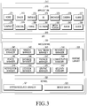
- FIG. 3 is a block diagram of a program module according to various embodiments.
- the program module 310 may include an Operating System (OS) that controls resources related to an electronic device (for example, the electronic device 101) and/or various applications (for example, the application 147) that run on the OS.
- the OS may be, for example, Android, iOS, Windows, Symbian, Tizen, Bada, or the like.
- the program module 310 may include a kernel 320, middleware 330, an API 360, and/or an application 370. At least part of the program module 310 may be preloaded onto the electronic device, or may be downloaded from an external electronic device (for example, the electronic device 102 or 104, the server 106, or the like).
- the kernel 320 may include, for example, a system resource manager 321 and/or a device driver 323.
- the system resource manager 321 may perform control, allocation, or recovery of system resources.
- the system resource manager 321 may include a process manager, a memory manager, or a file system manager.
- the device driver 323 may include, for example, a display driver, a camera driver, a Bluetooth driver, a shared memory driver, a USB driver, a keypad driver, a Wi-Fi driver, an audio driver, or an Inter-Process Communication (IPC) driver.
- IPC Inter-Process Communication
- the middleware 330 may provide, for example, functions commonly needed for applications 370, or may provide the applications 370 with various functions through the API 360 so that the applications 370 may efficiently use the limited systems resources in the electronic device.
- the middleware 330 (for example, the middleware 143) may include at least one of a runtime library 335, an application manager 341, a window manager 342, a multimedia manager 343, a resource manager 344, a power manager 345, a database manager 346, a package manager 347, a connectivity manager 348, a notification manager 349, a location manager 350, a graphic manager 351, and a security manager 352.
- the runtime library 355 may include, for example, a library module used by a complier to add a new function through a programming language while the application 370 is running.
- the runtime library 355 may perform functions for input/output management, memory management, or mathematical calculations.
- the application manager 341 may manage, for example, the life cycle of at least one application among the applications 370.
- the window manager 342 may manage graphic user interface (GUI) resources used for a screen.
- GUI graphic user interface
- the multimedia manager 343 may identify formats that are necessary to play various media files, and may encode or decode a media file using a codec suitable for a corresponding format.
- the resource manager 344 may manage resources, such as a source code, a memory, or a storage space, for at least one application among the applications 370.
- the power manager 345 may operate with, for example, a basic input/output system (BIOS) to manage a battery or power supply and may provide information on power necessary for operation of the electronic device.
- the database manager 346 may generate, retrieve, or change a database to be used for at least one application among the applications 370.
- the package manager 347 may install or update an application distributed in the form of a package file.
- the connectivity manager 348 may manage wireless connectivity, for example, via Wi-Fi or Bluetooth.
- the notification manager 349 may display or report an incoming message, an appointment, and an event including a proximity notification in a manner that does not disturb a user.
- the location manager 350 may manage location information on the electronic device.
- the graphic manager 351 may manage a graphic effect to be provided for the user or a user interface related to the graphic effect.
- the security manager 352 may provide overall security functions necessary for system security or user authentication. According to one embodiment, when the electronic device (for example, the electronic device 101) has phone features, the middleware 330 may further include a telephony manager to manage a voice or video call function of the electronic device.
- the middleware 330 may include a middleware module that forms combinations of various functions of the foregoing components.
- the middleware 330 may provide a specialized module for each type of OS in order to provide differentiated functions. Further, the middleware 330 may dynamically delete some of the existing components or add new components.
- the API 360 (for example, the API 145) is, for example, a set of API programming functions, and may be provided with a different configuration depending on the OS.
- one API set for each platform may be provided in the case of Android or iOS, while two or more API sets for each platform may be provided in the case of Tizen.
- the application 370 may include one or more applications that are capable of performing functions of, for example, a home screen 371, a dialer 372, SMS/MMS 373, instant messaging (IM) 374, a browser 375, a camera 376, an alarm 377, an address book 378, a voice dialer 379, email 380, a calendar 381, a media player 382, an album 383, a clock 384, or health care (for example, for measuring exercising or blood sugar), an environmental data application (for example, for providing atmospheric pressure, humidity, or temperature data), or the like.
- IM instant messaging
- the application 370 may include an application (hereinafter, "information exchange application” for convenience of description) that supports information exchange between the electronic device (for example, the electronic device 101) and an external electronic device (for example, the electronic device 102 or 104).
- the information exchange application may include, for example, a notification relay application for relaying specific information to the external electronic device or a device management application for managing the external electronic device.
- the notification relay application may include a function of relaying notification information, which is generated in another application (for example, the SMS/MMS application, the email application, the health care application, the environmental data application, or the like) of the electronic device, to the external electronic device (for example, the electronic device 102 or 104). Additionally, the notification relay application may receive notification information, for example, from the external electronic device and may provide the notification information to the user.
- another application for example, the SMS/MMS application, the email application, the health care application, the environmental data application, or the like
- the notification relay application may receive notification information, for example, from the external electronic device and may provide the notification information to the user.
- the device management application may manage (for example, install, delete, or update), for example, at least one function (for example, a function of turning on/turning off the external electronic device itself (or some components) or adjusting the brightness (or resolution) of a display) of the external electronic device (for example, the electronic device 102 or 104) communicating with the electronic device, an application operating in the external electronic device, or a service (for example, a call service or message service) provided by the external electronic device.
- at least one function for example, a function of turning on/turning off the external electronic device itself (or some components) or adjusting the brightness (or resolution) of a display
- the external electronic device for example, the electronic device 102 or 104
- a service for example, a call service or message service
- the application 370 may include an application (for example, a health care application of a mobile medical device) assigned according to the attributes of the external electronic device (for example, the electronic device 102 or 104).
- the application 370 may include an application received from the external electronic device (for example, the server 106 or the electronic device 102 or 104).
- the application 370 may include a third-party application that may be downloaded from a preloaded application or the server.
- the illustrated components of the program module 310, according to the embodiments, may be termed differently depending on the OS.
- At least part of the program module 310 may be implemented in software, firmware, hardware, or combinations of at least two or more. At least part of the program module 310 may be implemented (for example, run) by, for example, a processor (for example, the processor 210). At least part of the program module 310 may include, for example, a module, a program, a routine, sets of instructions, or a process to perform one or more functions.
- module as used herein may, for example, mean a unit including one of hardware, software, and firmware or a combination of two or more of them.
- the “module” may be interchangeably used with, for example, the term “unit”, “logic”, “logical block”, “component”, or “circuit”.
- the “module” may be a minimum unit of an integrated component element or a part thereof.
- the “module” may be a minimum unit for performing one or more functions or a part thereof.
- the “module” may be mechanically or electronically implemented.
- the "module” may include at least one of an Application-Specific Integrated Circuit (ASIC) chip, a Field-Programmable Gate Arrays (FPGA), and a programmable-logic device for performing operations which has been known or are to be developed hereinafter.
- ASIC Application-Specific Integrated Circuit
- FPGA Field-Programmable Gate Arrays
- programmable-logic device for performing operations which has been known or are to be developed hereinafter.
- At least some of the devices (for example, modules or functions thereof) or the method (for example, operations) according to the present disclosure may be implemented by a command stored in a computer-readable storage medium in a programming module form.
- the instruction when executed by a processor (e.g., the processor 120), may cause the one or more processors to execute the function corresponding to the instruction.
- the computer-readable storage medium may be, for example, the memory 130.
- the computer readable recoding medium may include a hard disk, a floppy disk, magnetic media (e.g., a magnetic tape), optical media (e.g., a Compact Disc Read Only Memory (CD-ROM) and a Digital Versatile Disc (DVD)), magneto-optical media (e.g., a floptical disk), a hardware device (e.g., a Read Only Memory (ROM), a Random Access Memory (RAM), a flash memory), and the like.
- the program instructions may include high class language codes, which can be executed in a computer by using an interpreter, as well as machine codes made by a compiler.
- the aforementioned hardware device may be configured to operate as one or more software modules in order to perform the operation of the present disclosure, and vice versa.
- the programming module may include one or more of the aforementioned components or may further include other additional components, or some of the aforementioned components may be omitted.
- Operations executed by a module, a programming module, or other component elements according to various embodiments of the present disclosure may be executed sequentially, in parallel, repeatedly, or in a heuristic manner. Furthermore, some operations may be executed in a different order or may be omitted, or other operations may be added.
- Various embodiments disclosed herein are provided merely to easily describe technical details of the present disclosure and to help the understanding of the present disclosure, and are not intended to limit the scope of the present disclosure. Accordingly, the scope of the present disclosure should be construed as including all modifications or various other embodiments based on the technical idea of the present disclosure.
- a storage medium stores instructions, wherein the instructions are configured for at least one processor to perform at least one operation when executed by the at least one processor, the at least one operation recording a program to perform: receiving, by an electronic device, data about touch or proximity of a stylus brush on or to a touch screen display from a touch panel of the display; determining an area detected due to the touch or proximity relative to the touch panel at least partially on the basis of the data; determining at least a portion having a relatively high signal strength in the area; determining at least another portion having a relatively low signal strength in the area; and displaying an image or a change in an image on the display on the basis of the positions and/or sizes of the determined areas.
- FIG. 4 is a block diagram 400 illustrating an electronic device according to various embodiments.
- the electronic device 401 may be, for example, the electronic device 101 illustrated in FIG. 1 .
- the electronic device 401 may include a display 410, a processor 420, and a memory 430.
- the display 410 may be, for example, the display 160 illustrated in FIG. 1 .
- the display 410 may be a touch screen display, and the touch screen display may include a touch panel capable of recognizing a touch operation using an external object, such as an input device or a body part of a user.
- the input device may include a stylus brush
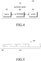
- FIG. 5 shows an illustrative configuration of a stylus brush.
- the stylus brush 500 includes a contact portion 510 and a body portion 520, the contact portion 510 including a plurality of elastic fibers and having unique conductivity.
- the contact portion 510 induces an electromagnetic field when coming in contact with or approaching the touch panel, and may include a conductive material other than carbon fiber.
- the touch panel is an electronic device capable of touch recognition
- FIG. 6 shows the illustrative configuration of the touch panel.
- the touch panel has a two-dimensional plane defined by an X profile and a Y profile, and employs a sensing mode using capacitance coupling with an AC voltage applied, in which user input using the input device or the body part of the user may be detected using a change in capacitance by detecting a touched area of a certain size or greater.
- the display 410 may detect data about the input (touch or proximity) with the input device of the body part of the user and may provide the detected data to the processor 420.
- the touch panel of the display 410 may detect the signal strength, the size (width and height), and the coordinates of an area in which the input with the stylus brush occurs and may provide the detected signal strength, size, and coordinates to the processor 420.
- the operation of detecting the data (signal strength, size, and coordinates) about the input with the input device is described below with reference to FIG. 7 .
- FIG. 7 illustrates the detection of data about input with an input device in a display of an electronic device according to various embodiments.
- the touch panel may obtain raw data by identifying sensor information at intersections A, B, C, and D of Tx and Rx, may detect a signal strength and a size (width and height) relating to the input (touch or proximity) with the input device by combing the obtained raw data, and may provide the signal strength and size (width and height) to the processor 420.
- the processor 420 may be the processor 120 illustrated in FIG 1 .
- the processor 410 may include, for example, one of hardware, software, and firmware, or a combination of at least two thereof.
- the processor 420 may determine the type of the input device using data about the input (touch or proximity) through the input device, which performs input into (touches or approaches) the display 410.
- the processor 420 may detect the type of the input device from the memory 430 using at least one of a signal strength value and a size (width and height) value received from the display 410. Information on the type of input device based on signal strength and size is predefined and stored in the memory 430. The processor 420 may determine that the input device is a stylus brush using the signal strength and size received from the display 410 based on the information previously stored in the memory 430.
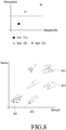
- FIG. 8 illustrates an operation of detecting the type of the input device using material characteristics of the input device in an electronic device according to various embodiments.
- the input device has unique signal strength and a different contact size depending on the type thereof, and can be distinguished by the contact size and the signal strength.
- a stylus pen has a size of 1 ⁇ and a signal strength of 74.5.
- an area on a two-dimensional plane may be distinguished by a size (radius) and strength, an input device that satisfies both signal strength and a size in each area is defined in advance, and information on the type of input device defined in each area may be stored in the memory 430.
- the input device predefined in each area may include a stylus pen input 801, an input 802 based on the type of a stylus brush, a user finger-touch input 803, and a palm-touch input 804.
- the processor 420 may detect the types of input devices having similar patterns by identifying the form, size, and travelling path of an input device, which are recognized during the use of the input device.
- the processor 420 may detect the form and travelling path of the input device using at least one of the coordinates, the signal strength, and the size (width and height) received from the display 410 during the use of the input device.
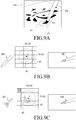
- FIGS. 9A to 9C illustrates an operation of detecting the form of an input device in an electronic device according to various embodiments.
- the form, size, and end portion of a contact portion 911 of the brush may be identified based on the signal strength and the size of the contact portion 911 of the stylus brush 910 that is in contact with the display 410.
- a center point a1 of the contact portion 911 of the brush has a large contact size and high signal strength and an end point b1 has a small contact size and low signal strength.
- the processor 420 may determine the type of the stylus brush based on the form of the stylus brush. As illustrated in FIG.
- the processor 420 may determine that a first stylus brush 920 has been brought into contact with the display 410. As illustrated in FIG. 9C , when a center point a3 and a plurality of end points b3 are detected based on the coordinates, signal strength, and size received from the display 410, the processor 420 may determine that a second stylus brush 930 has been brought into contact with the display 410.
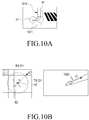
- FIGS. 10A to 10D illustrate an operation of detecting the travelling direction of an input device in an electronic device according to various embodiments.
- the travelling direction of the brush 1010 may be predicted based on the signal strength, the size, and the distribution form of a contact portion 10111 of the stylus brush 1010 that is in contact with the display 410.
- the travelling direction of the brush 1010 may be predicted based on the positions of a center point a1 and an end point b1 of the contact portion 1011 of the brush 1010 and the travelling positions thereof.
- the processor 420 may detect a center point a2 and an end point b2 of a contact portion of a brush 1020 based on the coordinates, signal strength, and size received from the display 410, may detect the positions of the detected center point a2 and end point b2, and may predict a direction starting from the end point b2 to the center point a2 as the travelling direction d1 of the brush 1020. As illustrated in FIG. 10B , the processor 420 may detect a center point a2 and an end point b2 of a contact portion of a brush 1020 based on the coordinates, signal strength, and size received from the display 410, may detect the positions of the detected center point a2 and end point b2, and may predict a direction starting from the end point b2 to the center point a2 as the travelling direction d1 of the brush 1020. As illustrated in FIG.
- the processor 420 may detect a center point and an end point of a contact portion of a brush 1030 based on the coordinates, signal strength, and size received from the display 410, and may detect the travelling position of any one of the center point and the end point, for example, the center point a3.
- the processor 420 may detect a similar pattern corresponding to the detected travelling position of the center point a3 from the memory 430, and may predict the travelling direction d1 of the brush 1030.
- the processor 420 may detect a center point a4 and a plurality of end points d4 of a contact portion of a brush 1040 based on the coordinates, signal strength, and size received from the display 410.
- the processor 420 may predict the travelling direction d1 of the brush 1040 based on the distribution of the plurality of end points d4 disposed around the center point a4. Alternatively, the processor 420 may predict the travelling direction based on variation in the distribution of the plurality of end points d4 while drawing with the brush 1040. For example, when the user draws with the brush 420 in the horizontal direction and then changes the travelling direction of the brush 420 to the vertical direction, the distribution of the plurality of end points d4 is changed, and thus the travelling direction may be predicted based on variation in the distribution of the plurality of end points d4. In addition, the processor 420 may predict the travelling direction of the brush based only on the form of a contact portion of a stylus brush.
- FIG. 11 illustrates an operation of detecting the type of input device while using the input device in an electronic device.
- the processor 420 may predict the form and the travelling direction of the stylus brush 1110, thus determining that an input device that performs input to the display 410 is the stylus brush 1110.
- the processor 420 may determine the type of the input device using the signal strength, among the coordinates, the signal strength, and the size received from the display 410. When the signal strength is less than or equal to a first threshold value, the processor 420 may determine that the input device is a stylus pen and may select a first routine. When the signal strength is greater than or equal to a second threshold value, which is greater than the first threshold value, the processor 420 may determine that the input device is a body part of the user, and may select a second routine. When the signal strength is between the first threshold value and the second threshold value, the processor 420 may determine that the input device is a stylus brush, and may select a third routine.
- the processor 420 may provide a menu for selecting an input device, and may determine the type of input device selected by the user from the menu.
- FIG. 12 illustrates an operation of selecting an input device in an electronic device according to various embodiments. As illustrated in FIG. 12 , the processor 420 may determine the type of input device selected by the user from a menu including types of input devices.
- the processor 420 may determine the type of input device through a sensor of the electronic device.
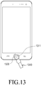
- FIG. 13 illustrates an operation of detecting an input device in an electronic device according to various embodiments.
- the processor 420 may detect the form and size of the input device based on sensor information received through the sensor unit 1320, and may determine that the input device is a stylus brush 1310 based on the detected form and size.
- the processor 420 may calibrate a start point.
- the drawing starts from the end portion of the brush.
- a center point of the brush is recognized as a start point, so that the user may experience a sense of displacement.
- the processor 420 may determine an end portion of a contact portion of the brush based on the contact size, the strength, and the distribution form ( FIGS. 9 and 10 ) of the contact portion of the stylus brush, and may perform calibration such that a drawing starts from the end portion of the contact portion of the brush.
- the processor 420 may predict the drawing direction of the moving brush ( FIGS.
- the processor 420 may calibrate a drawing based on dispersed positions.
- FIGS. 14A to 15B illustrate an operation of calibrating a brush drawing in an electronic device according to various embodiments.
- a drawing is executed using a stylus brush
- calibration may be performed such that the start point is changed from the center point a1 to an end point b1, as illustrated in FIG. 14B , and thus the drawing starts from the end point b1.
- the travelling direction d1 of the brush may be predicted as illustrated in FIG.
- the processor 420 may provide various drawing effects using at least one of strength, speed, phase, and the type of the brush (the form of a contact portion of the brush) resulting from the stylus brush that is input to (touches or approaches) the display 410.
- the processor 420 may detect a center point and an end point using coordinates, signal strength, and a size received from the display 410, and may then provide realistic drawing effects based on the movements of the center point and the end point.
- FIGS. 16A and 16B illustrate a drawing effect based on the trajectory change of a center point and an end point of an input device in an electronic device according to various embodiments.
- the processor 420 may detect a center point a1 and an end point b1 using coordinates, signal strength and a size received from the display 410, and may provide drawing effects based on the trajectory change a2 of the center point a1 and the trajectory change b2 of the end point b1.
- the processor 420 may detect a center point and an end point using coordinates, signal strength, and a size received from the display 410, and may then provide various drawing effects, for example, gradation, airbrush, and density variation effects, based on a speed difference, a phase difference therebetween, and strength between the center point and the end point.
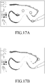
- FIGS. 17A and 17B illustrate a drawing effect based on the adjustment of a center point and an end point of an input device in an electronic device according to various embodiments. As illustrated in FIG. 17A and 17B , while the stylus brush is in contact with the display, various drawing effects may be provided by adjusting the speed difference, the phase difference, and the strength between the center point and the end point.
- the processor 420 may detect a center point and an end point using coordinates, signal strength, and a size received from the display 410, and may then provide various dry brush effects based on a speed difference, a phase difference, and strength between the center point and the end point, for example, a dry brush calligraphy effect when the speed difference is a threshold value or greater and a dry brush drawing effect when the speed difference is less than the threshold value.
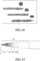
- FIG. 18 illustrates a dry brush effect based on the adjustment of a center point and an end point of an input device in an electronic device according to various embodiments. As illustrated in FIG. 18 , while the stylus brush is in contact with the display, various dry brush effects may be provided by adjusting the speed difference, the phase difference, and the strength between the center point and the end point.
- the processor 420 may determine the type of the brush (the form of a contact portion of the brush) based on coordinates, signal strength, and a size received from the display 410.
- the processor 420 may execute a drawing with a color predefined for the type of the brush, or may apply a drawing effect predefined for the type of the brush.
- the processor 420 may detect a center point and an end point using coordinates, signal strength, and a size received from the display 410, and may then execute a drawing with a plurality of colors predefined for respective intervals from the center point to the end point.
- FIG. 19 illustrates a drawing of various colors based on the contact of a contact portion of an input device in an electronic device according to various embodiments. Referring to FIG. 19 , different colors may be predefined for respective intervals c1 to c4 from an end point b1 to a center point a1 of the contact portion 1911 of the stylus brush.
- FIG. 20 illustrates a function performed corresponding to the contact form of a stylus brush in an electronic device according to various embodiments.
- a function corresponding to the circular form for example, an eraser function
- the eraser function may be performed to erase a drawing.
- the processor 420 may detect a center point and an end point using coordinates, signal strength, and a size received from the display 410, and may then provide a scratch effect based on the distance and strength between the center point and the end point.
- FIG. 21 illustrates a scratch effect using a stylus brush in an electronic device according to various embodiments. As illustrated in FIG. 21 , the depth of a scratch may be adjusted according to the distance h and strength between a center point b1 and an end point a1 of the stylus brush, and the width of the scratch effect may be adjusted according to the contact angle of the stylus brush.
- the processor 420 may implement various drawing effects depending on the attributes of an end portion (tip) of a stylus brush. Various drawing effects may be implemented depending on the strength of the end portion (tip) of the stylus brush, for example, when the end portion (tip) of the stylus brush holds a large amount of water or when the end portion (tip) of the stylus brush easily evaporates water.
- the processor 420 may implement a predefined drawing effect depending on at least one of the speed, time difference, length, and attributes of the end portion (tip) of the stylus brush.
- the processor 420 may provide various drawing effects using proximity input with a stylus brush.
- a touch sensor provided in the display 410 or a sensor of the electronic device receives hovering of the brush or distinguishes hovering from contact using a specified threshold value
- the processor may provide various drawing effects according to hovering of the brush.
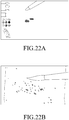
- FIGS. 22A and 22B illustrate a drawing effect according to hovering of an input device in an electronic device according to various embodiments. As illustrated in FIG. 22A , when hovering of a stylus brush is recognized and the brush remains stationary at the same position for a certain period of time or longer, the processor 420 may provide a water-dripping drawing effect.
- the water-dripping drawing effect may provide various water drop-spreading effects according to the height of the hovering brush, the type and properties of the brush. As illustrated in FIG. 22B , when hovering of a stylus brush is recognized and then the position, height, or angle of the brush sharply changes (for example, a brush-shaking motion is made), the processor 420 may provide a water-spraying drawing effect.
- the water-spraying drawing effect may provide a wider water-spraying drawing effect as the brush has a greater positional change and a greater height, and a water-spraying direction may be determined depending on the angle of the brush.
- the processor 420 may provide various forms of drawing effects depending on at least one of the speed, time difference, length, and attributes of the end portion (tip) of the stylus brush.
- the processor 420 may store frequently used drawing patterns and may prioritize the stored drawing patterns according to the frequency of use. For example, when curves are frequently drawn by a user, dry brushing for curve drawing may be preferentially set and applied.
- the processor 420 may distinguish a portion that the brush touches from a portion where hovering of the brush is detected by combining a change in a state of hovering resulting from the proximity of the stylus brush to the display 410 and a touch signal resulting from the touch of the stylus brush, thereby providing a more detailed drawing effect for the portion that the brush touches.
- the processor 420 may perform a function designated based on the type of a gesture occurring by touch input, rather than input using the stylus brush.
- the processor 420 may perform a function designated based on the shape, size, and strength of an area generated by touch input, rather than input using the brush, for example, screen zoom-in/zoom-out or attributes (color, thickness, type, or the like) of the brush.
- FIG. 23 illustrates an operation of performing a zoom-in/zoom-out function using input with a stylus brush in an electronic device according to various embodiments.
- the processor 420 may perform a screen zoom-in function.
- the processor 420 may perform a screen zoom-out function.
- FIG. 24 illustrates an operation of providing a function of changing the attribute of a stylus brush using input with the stylus brush in an electronic device according to various embodiments.
- the processor 420 may adjust the thickness of the brush corresponding to the traveling distance of the user's finger 2420. Further, when a gesture of left-to-right input or right-to-left input with the user's finger 2420 is generated with input using the stylus brush 2410, the processor 420 may change the color of the brush corresponding to the traveling distance of the user's finger 2420.
- the processor 420 may switch to a function implementation mode based on the attributes of a stylus brush, such as strength based on input and the distance between the center point and the end point.
- the processor 420 may provide different operations depending on the attributes of the brush in the function implementation mode. For example, when the strength of the brush is low and the distance between the center point and the end point is a certain length or less, which is defined as the function implementation mode, the processor 420 may provide an operation different from general brush input.
- FIG. 25 illustrates an operation of performing a particular function using a stylus brush in an electronic device according to various embodiments. As illustrated in FIG.
- the plurality of icons when a plurality of icons respectively corresponding to a plurality of applications exists in a particular folder in the function implementation mode switched according to the attributes of input with the stylus brush, the plurality of icons may be rotated by the input with the brush, for example, drawing input in a particular direction, thereby identifying the types of the icons provided in the folder. Further, when a particular icon is selected by the brush among the plurality of icons, an application corresponding to the selected icon may be executed.
- the processor 420 may execute a drawing application, and the drawing application may reflect the content of drawing based on input using the brush. For example, when the user performs input to the display 410 using the stylus brush during the execution of a particular application, the processor 420 may make content input using the brush into a background in an LCD buffer and may immediately execute the drawing application, thus reflecting and displaying the content of the drawing input using the brush.
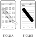
- FIGS. 26A and 26B illustrate an application execution operation using a stylus brush in an electronic device according to various embodiments. When input with the stylus brush is recognized while a home screen including a plurality of icons is displayed, as illustrated in FIG. 26A , a memo application is automatically executed, as shown in FIG. 26B , and a drawing corresponding to the input with the brush entered onto the home screen may be reflected and displayed as it is on a screen displaying the executed memo application.
- the processor 420 may provide the same drawing effect as that of a stylus brush using input with a stylus pen.
- the processor 420 may provide the same effect as that of a stylus brush depending on the material and form of the stylus pen.
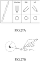
- FIGS. 27A and 27B illustrate an operation of providing a drawing effect of a stylus brush using input with a stylus pen in an electronic device according to various embodiments. As illustrated in FIG. 27A , when an end portion (tip) of a contact portion of the stylus pen is a hard type, the contact curvature of the pen changes depending on the input angle of the pen, making it possible to predict the travelling direction of the pen.
- the processor 420 may provide the same drawing effect as that of the stylus brush between the start position of the pen and the position to which the same is moved.
- the end portion (tip) of the contact portion of the stylus pen is made of an elastic material
- the form of the elastic body may change depending on the input angle and the input strength of the pen to corresponding to input with the stylus brush.
- Output corresponding to the stylus brush may be displayed on the screen using the measured angle, strength, and contact size corresponding to the input with the pen.
- the processor 420 may change the output attributes of a stylus brush or a stylus pen using buttons provided on the stylus brush or stylus pen.
- the processor 420 may provide an attribute change, such as a mode change, a color change, and an eraser function, through input via a button provided on the stylus brush or the stylus pen.
- FIGS. 28A to 28C illustrate an operation of performing a particular function using a button of a stylus pen in an electronic device according to various embodiments.
- the processor 420 may start recording when the button 2811 provided in the stylus pen 2810 is pressed as illustrated in FIG.
- FIG. 28A may terminate recording when an object t1 drawn with the pen 2810 is output and the button 2811 of the stylus pen 2810 is pressed again as illustrated in FIG. 28B ; and may automatically generate and display the same object t2 as the drawn object t1 as illustrated in FIG. 28C .
- the memory 430 may be the memory 130 illustrated in FIG 1 . According to one embodiment, the memory 430 may store the type of input device and signal strength and a size corresponding to the type of the input device in a corresponding manner. According to one embodiment, the memory 430 may store instructions for the processor 420 to perform operations according to various embodiments of the present disclosure.
- the processor 420 may detect a center point or an end point based on coordinates, signal strength, and a size received from the display 410, and may select an object based on the position of one of the center point and the end point.
- the processor 420 may select the object and may perform a function corresponding to the selected object.
- the processor 420 may select the object and may perform a function corresponding to the selected object.
- the processor 420 may select the object and may perform a function corresponding to the selected object.
- the processor 420 may select the object and may perform a function corresponding to the selected object.
- a touch screen display 410 may include a touch panel, a processor 420 may be electrically connected to the display, and a memory 430 may be electrically connected to the processor.
- the memory 430 may be configured to store instructions that, when executed, enable the processor 420 to: receive, from the touch panel, data about touch or proximity of an external object on or to the touch screen display; select one of a first routine, a second routine, and a third routine at least partially on the basis of the data; process the data using the selected one routine; and display an image or a change in an image on the display based on the processed data.
- the instructions may be configured to enable the processor 420 to: select the first routine when the external object is a stylus pen; select the second routine when the external object is a body part of a user; and select the third routine when the external object is a stylus brush.
- the instructions may be configured to enable the processor 420 to determine the type of the brush on the basis of the data when the third routine is selected.
- the instructions may be configured to enable the processor 420 to display an image or a change in an image on the display at least partially on the basis of the determined type of the brush.
- the instructions may be configured to enable the processor 420 to display an effect corresponding to the type of the brush on the display at least partially on the basis of the data after the first routine or the second routine is selected.
- the data about the touch or proximity may include at least one of coordinates, a size, and a signal strength detected due to the touch or proximity relative to the touch panel.
- the instructions may be configured to enable the processor 420 to select one of the first routine, the second routine, and the third routine at least partially on the basis of the level of the signal strength.
- the instructions may be configured to enable the processor 420 to: select the first routine when the level of the signal strength is less than or equal to a first threshold value; select the second routine when the level of the signal strength is greater than or equal to a second threshold value, which is greater than the first threshold value; and select the third routine when the level of the signal strength is between the first threshold value and the second threshold value.
- the instructions may be configured to enable the processor 420 to determine the type of the brush at least partially on the basis of the detected size after the third routine is selected.
- the instructions may be configured to enable the processor 420 to: determine an area detected due to the touch or proximity relative to the touch panel at least partially on the basis of the data; determine a first sub-area having relatively high signal strength in the area; and display an image or a change in an image on the display on the basis of the position and/or size of the determined sub-area.
- a touch screen display 410 may include a touch panel, a processor 420 may be electrically connected to the display 410, and a memory 430 may be electrically connected to the processor 420.
- the memory 430 may be configured to store instructions that, when executed, enable the processor 420 to: receive, from the touch panel, data about touch or proximity of a stylus brush on or to the touch screen display; determine an area detected due to the touch or proximity relative to the touch panel at least partially on the basis of the data; determine at least a portion having relatively high signal strength in the area; determine at least another portion having relatively low signal strength in the area; and display an image or a change in an image on the display on the basis of positions and/or sizes of the determined areas.
- the data about the touch or proximity may include at least one of a coordinate, a size, and signal strength detected due to the touch or proximity relative to the touch panel.
- the instructions may be configured to enable the processor 420 to determine at least one of the type of the brush and the drawing direction of the brush on the basis of the positions and/or sizes of the determined areas.
- the instructions may be configured to enable the processor 420 to display an image or a change in an image on the display at least partially on the basis of the determined type of the brush and the determined drawing direction of the brush.
- the instructions may be configured to enable the processor 420 to execute a drawing with different colors at least partially on the basis of the determined type of the brush and the determined drawing direction of the brush.
- the instructions may be configured to enable the processor 420 to display a start of a drawing from the at least another portion at least partially on the basis of the determined type of the brush and the determined drawing direction of the brush.
- the instructions may be configured to enable the processor 420 to display different drawing effects on the display using at least one of a speed difference, a phase difference, and a signal strength difference between the determined areas.
- the instructions may be configured to enable the processor 420 to display different drawing effects on the display on the basis of the proximity distance between the brush and the touch screen display.
- a touch screen display 410 may include a touch panel, a processor 420 may be electrically connected to the display 410, and a memory 430 may be electrically connected to the processor 420.
- the memory 430 may be configured to store instructions that, when executed, enable the processor 420 to: receive, from the touch panel, data about touch or proximity of a stylus brush on or to the touch screen display; determine an area detected due to the touch or proximity relative to the touch panel at least partially on the basis of the data; determine at least a portion having relatively high signal strength in the area; determine at least another portion having relatively low signal strength in the area; and select an object on the basis of the position of any one of the at least a portion and the at least another portion.
- the instructions may be configured to enable the processor 420 to select the object on the basis of the position of the at least another portion when the at least a portion is not determined.
- the instructions may be configured to enable the processor 420 to perform a function corresponding to the object when the at least another portion is located in the area of the object and the at least a portion is located outside the area of the object or in at least a portion of the area of the object.
- FIG. 29 is a flowchart illustrating an input method of an electronic device.
- FIG. 29 illustrates an example in which the processor 420 of the electronic device 401 of FIG. 4 performs the input method 2900 of the electronic device according to various embodiments.
- the processor 420 may receive input via the input device based on data (for example, coordinates, signal strength, and size) about the input with the input device received from the display 410.
- the processor 420 may determine the type of the input device based on the data (for example, coordinates, signal strength, and size) received from the display 410.
- the processor 420 may determine that the input device is a stylus brush based on the data (for example, coordinates, signal strength, and size) received from the display 410.
- the processor 420 may determine the type of the stylus brush (the form of a contact portion of the stylus brush) based on the data (for example, coordinates, signal strength, and size) received from the display 410. In operation 2909, the processor 420 may provide a drawing corresponding to the type of the stylus brush and may display an image or a change in an image on the display 410 while receiving the input with the stylus brush.
- the processor 420 may determine that the input device is a stylus pen based on the data (for example, coordinates, signal strength, and size) received from the display 410.
- the processor 420 may provide a drawing corresponding to the stylus pen and may display an image or a change in an image on the display 410 while receiving the input with the stylus pen.
- the processor 420 may determine that the input device is a body part of a user, for example, a finger, based on the data (for example, coordinates, signal strength, and size) received from the display 410.
- the processor 420 may provide a drawing corresponding to the finger of the user, and may display an image or a change in an image on the display 410 while receiving the input made with the finger of the user.
- An input method of an electronic device may include: receiving, from a touch panel, data about touch or proximity of an external object on or to a touch screen display; selecting one of a first routine, a second routine, and a third routine at least partially on the basis of the data; processing the data using the selected one routine; and displaying an image or a change in an image on the display on the basis of the processed data.
- the selecting may include: selecting the first routine when the external object is a stylus pen; selecting the second routine when the external object is a body part of a user; and selecting the third routine when the external object is a stylus brush.
- the method may further include determining the type of the brush on the basis of the data when the third routine is selected.
- the method may further include displaying an image or a change in an image on the display at least partially on the basis of the determined type of the brush.
- the method may further include displaying an effect corresponding to the type of the brush on the display at least partially on the basis of the data after the first routine or the second routine is selected.
- the data about the touch or proximity may include at least one of coordinates, a size, and a signal strength detected due to the touch or proximity relative to the touch panel.
- the method may further include selecting one of the first routine, the second routine, and the third routine at least partially on the basis of the level of the signal strength.
- the selecting of one of the first routine, the second routine, and the third routine may include: selecting the first routine when the level of the signal strength is less than or equal to a first threshold value; selecting the second routine when the level of the signal strength is greater than or equal to a second threshold value, which is greater than the first threshold value; and selecting the third routine when the level of the signal strength is between the first threshold value and the second threshold value.
- the method may further include determining the type of the brush at least partially on the basis of the detected size after the third routine is selected.
- the method may further include: determining an area detected due to the touch or proximity relative to the touch panel at least partially on the basis of the data; determining a first sub-area having relatively high signal strength in the area; and displaying an image or a change in an image on the display on the basis of the position and/or size of the determined sub-area.
- an input method of an electronic device may include: receiving, by an electronic device, data about touch or proximity of a stylus brush on or to a touch screen display from the touch panel; determining an area detected due to the touch or proximity relative to the touch panel at least partially on the basis of the data; determining at least a portion having relatively high signal strength in the area; determining at least another portion having relatively low signal strength in the area; and displaying an image or a change in an image on the display on the basis of positions and/or sizes of the determined areas.
- the data about the touch or proximity may include at least one of coordinates, a size, and a signal strength detected due to the touch or proximity relative to the touch panel.
- the method may further include determining at least one of the type of the brush and the drawing direction of the brush on the basis of the positions and/or sizes of the determined areas.
- the method may further include displaying an image or a change in an image on the display at least partially on the basis of the determined type of the brush and the determined drawing direction of the brush.
- the method may further include executing a drawing with different colors at least partially on the basis of the determined type of the brush and the determined drawing direction of the brush.
- the method may further including a calibration operation of displaying a start of a drawing from the at least another portion at least partially on the basis of the determined type of the brush and the determined drawing direction of the brush.
- the method may further include displaying different drawing effects on the display using at least one of a speed difference, a phase difference, and a signal strength difference between the determined areas.
- the method may further include displaying different drawing effects on the display on the basis of the proximity distance between the brush and the touch screen display.
Claims (15)
- Dispositif électronique (401) comprenant :une unité d'affichage à écran tactile (410) configurée pour comprendre un panneau tactile ;un processeur (420) configuré pour être connecté électriquement à l'unité d'affichage à écran tactile ; etune mémoire (430) configurée pour être connectée électriquement au processeur,où la mémoire est configurée pour stocker des instructions qui, lorsqu'elles sont exécutées, permettent au processeur de :recevoir, à partir du panneau tactile, des données sur le contact ou la proximité d'un stylet à brosse sur ou à l'unité d'affichage à écran tactile ;identifier une première zone du panneau tactile associée au contact ou à la proximité du stylet à brosse par rapport au panneau tactile en fonction au moins partiellement des données ;identifier une deuxième zone correspondant à une intensité de signal relativement élevée dans la première zone ;identifier une troisième zone correspondant à une intensité de signal relativement faible dans la première zone ; etafficher au moins une image sur l'unité d'affichage à écran tactile en fonction de positions et/ou de dimensions de la première zone, la deuxième zone et la troisième zone.
- Dispositif électronique selon la revendication 1, où les instructions sont configurées pour permettre au processeur de : afficher de différents effets de dessin sur l'unité d'affichage à écran tactile en fonction d'une distance de proximité entre le stylet à brosse et l'unité d'affichage à écran tactile, et
les données sur le contact ou la proximité comprennent au moins une parmi des coordonnées, une dimension et une intensité de signal détectées en raison du contact ou de la proximité du stylet à brosse par rapport au panneau tactile. - Dispositif électronique selon la revendication 1, où les instructions sont configurées pour permettre au processeur d'identifier au moins un parmi un type du stylet à brosse et une direction de dessin du stylet à brosse en fonction des positions et/ou des dimensions de la première zone, la deuxième zone et la troisième zone.
- Dispositif électronique selon la revendication 3, où les instructions sont configurées pour permettre au processeur d'afficher l'au moins une image sur l'unité d'affichage à écran tactile en fonction au moins partiellement du type identifié du stylet à brosse et de la direction de dessin identifiée du stylet à brosse.
- Dispositif électronique selon la revendication 3, où les instructions sont configurées pour permettre au processeur d'exécuter un dessin avec de différentes couleurs en fonction au moins partiellement du type identifié du stylet à brosse et de la direction de dessin identifiée du stylet à brosse.
- Dispositif électronique selon la revendication 3, où les instructions sont configurées pour permettre au processeur d'afficher un début d'un dessin à partir de la troisième zone en fonction au moins partiellement du type identifié du stylet à brosse et de la direction de dessin identifiée du stylet à brosse.
- Dispositif électronique selon la revendication 1, où les instructions sont configurées pour permettre au processeur d'afficher de différents effets de dessin sur l'unité d'affichage à écran tactile en utilisant au moins une parmi une différence de vitesse, une différence de phase et une différence d'intensité de signal entre la première zone, la deuxième zone et la troisième zone.
- Procédé d'entrée d'un dispositif électronique (401), le procédé comprenant :la réception (2901), par un dispositif électronique, de données sur le contact ou la proximité d'un stylet à brosse sur ou à une unité d'affichage à écran tactile (410) par rapport à un panneau tactile de l'unité d'affichage à écran tactile ;l'identification d'une première zone du panneau tactile associée au contact ou à la proximité du stylet à brosse par rapport au panneau tactile en fonction au moins partiellement des données ;l'identification d'une deuxième zone correspondant à une intensité de signal relativement élevée (a1) dans la première zone ;l'identification d'une troisième zone correspondant à une intensité de signal relativement faible (b1) dans la première zone ; etl'affichage d'au moins une image sur l'unité d'affichage à écran tactile en fonction de positions et/ou dimensions de la première zone, la deuxième zone et la troisième zone.
- Procédé selon la revendication 8, comprenant en outre :l'affichage de différents effets de dessin sur l'unité d'affichage à écran tactile en utilisant au moins une parmi une différence de vitesse, une différence de phase et une différence d'intensité de signal entre la première zone, la deuxième zone et la troisième zone,où les données sur le contact ou la proximité comprennent au moins une parmi des coordonnées, une dimension et une intensité de signal détectées en raison du contact ou de la proximité du stylet à brosse par rapport au panneau tactile.
- Procédé selon la revendication 8, comprenant en outre :
l'identification d'au moins un parmi un type du stylet à brosse et une direction de dessin du stylet à brosse sur la base des positions et/ou des dimensions de la première zone, de la deuxième zone et de la troisième zone. - Procédé selon la revendication 10, comprenant en outre :
l'affichage de l'au moins une image sur l'unité d'affichage à écran tactile en fonction au moins partiellement du type identifié du stylet à brosse et de la direction de dessin identifiée du stylet à brosse. - Procédé selon la revendication 10, comprenant en outre :
l'exécution d'un dessin avec de différentes couleurs en fonction au moins partiellement du type identifié du stylet à brosse et de la direction de dessin identifiée du stylet à brosse. - Procédé selon la revendication 10, comprenant en outre :
l'affichage d'un début d'un dessin à partir de l'au moins une autre partie en fonction au moins partiellement du type identifié du stylet à brosse et de la direction de dessin identifiée du stylet à brosse. - Dispositif électronique comprenant :une unité d'affichage à écran tactile configurée pour comprendre un panneau tactile ;un processeur configuré pour être électriquement connecté à l'unité d'affichage à écran tactile ; etune mémoire configurée pour être connectée électriquement au processeur,où la mémoire est configurée pour stocker des instructions qui, lorsqu'elles sont exécutées, permettent au processeur de :recevoir, à partir du panneau tactile, des données sur le contact ou sur la proximité d'un stylet à brosse sur ou à l'unité d'affichage à écran tactile ;identifier une première zone du panneau tactile associée au contact ou à la proximité du stylet à brosse par rapport au panneau tactile en fonction au moins partiellement des données ;identifier une deuxième zone correspondant à une intensité de signal relativement élevée dans la première zone ;identifier une troisième zone correspondant à une intensité de signal relativement faible dans la première zone ; etsélectionner un objet sur l'écran tactile en fonction d'une position de l'une quelconque de la deuxième zone et la troisième zone.
- Dispositif électronique selon la revendication 14, où les instructions sont configurées pour permettre au processeur de : effectuer une fonction correspondant à l'objet lorsque la troisième zone est située dans une zone de l'objet et que la deuxième zone est située en dehors de la zone de l'objet ou dans au moins une partie de la zone de l'objet.
Applications Claiming Priority (2)
| Application Number | Priority Date | Filing Date | Title |
|---|---|---|---|
| KR1020150114340A KR102388590B1 (ko) | 2015-08-13 | 2015-08-13 | 전자 장치 및 전자 장치의 입력 방법 |
| PCT/KR2016/008853 WO2017026821A1 (fr) | 2015-08-13 | 2016-08-11 | Dispositif électronique et procédé d'entrée de dispositif électronique |
Publications (3)
| Publication Number | Publication Date |
|---|---|
| EP3336675A1 EP3336675A1 (fr) | 2018-06-20 |
| EP3336675A4 EP3336675A4 (fr) | 2018-08-01 |
| EP3336675B1 true EP3336675B1 (fr) | 2019-12-04 |
Family
ID=57984349
Family Applications (1)
| Application Number | Title | Priority Date | Filing Date |
|---|---|---|---|
| EP16835461.1A Active EP3336675B1 (fr) | 2015-08-13 | 2016-08-11 | Dispositifs électroniques et procédé d'entrée de dispositif électronique |
Country Status (5)
| Country | Link |
|---|---|
| US (1) | US10564751B2 (fr) |
| EP (1) | EP3336675B1 (fr) |
| KR (1) | KR102388590B1 (fr) |
| CN (1) | CN107924286B (fr) |
| WO (1) | WO2017026821A1 (fr) |
Families Citing this family (6)
| Publication number | Priority date | Publication date | Assignee | Title |
|---|---|---|---|---|
| JP6087468B1 (ja) * | 2016-09-21 | 2017-03-01 | 京セラ株式会社 | 電子機器 |
| SE1830086A1 (en) | 2018-03-16 | 2019-09-17 | Flatfrog Lab Ab | A touch-sensitive apparatus |
| CN108827146A (zh) * | 2018-06-14 | 2018-11-16 | 苏州富莱智能科技有限公司 | Twain标准显微测量系统及测量方法 |
| KR102536263B1 (ko) | 2018-08-02 | 2023-05-25 | 삼성전자주식회사 | 스타일러스 펜의 입력을 표시하기 위한 방법 및 그 전자 장치 |
| EP4104042A1 (fr) | 2020-02-10 | 2022-12-21 | FlatFrog Laboratories AB | Appareil de détection tactile amélioré |
| KR102529821B1 (ko) * | 2023-01-05 | 2023-05-08 | (주) 아하 | 융합 터치스크린 패널에서 필압 감지 및 필압을 처리하는 방법 및 이를 위한 전자칠판 |
Family Cites Families (20)
| Publication number | Priority date | Publication date | Assignee | Title |
|---|---|---|---|---|
| US5488204A (en) * | 1992-06-08 | 1996-01-30 | Synaptics, Incorporated | Paintbrush stylus for capacitive touch sensor pad |
| JP3432149B2 (ja) | 1998-07-13 | 2003-08-04 | 株式会社島精機製作所 | 画像処理方法とその装置 |
| KR20060084945A (ko) * | 2005-01-21 | 2006-07-26 | 엘지전자 주식회사 | 터치 패드 기반의 붓 효과 생성방법 |
| CN101833390B (zh) * | 2009-03-10 | 2014-07-02 | 阿尔派株式会社 | 电子设备及其输入处理方法 |
| US20100245286A1 (en) * | 2009-03-25 | 2010-09-30 | Parker Tabitha | Touch screen finger tracking algorithm |
| US8610744B2 (en) * | 2009-07-10 | 2013-12-17 | Adobe Systems Incorporated | Methods and apparatus for natural media painting using proximity-based tablet stylus gestures |
| US9372579B2 (en) * | 2009-10-27 | 2016-06-21 | Atmel Corporation | Touchscreen electrode arrangement |
| CN102096518B (zh) * | 2009-12-14 | 2013-12-25 | 联想(北京)有限公司 | 电子设备及输入方法 |
| US8797280B2 (en) | 2010-05-26 | 2014-08-05 | Atmel Corporation | Systems and methods for improved touch screen response |
| WO2013013225A1 (fr) * | 2011-07-21 | 2013-01-24 | Pengo Creative Inc. | Procédé et appareil pour la reconnaissance et l'affichage d'entrée de pinceau pour dispositifs à écran tactile |
| JPWO2013057862A1 (ja) * | 2011-10-20 | 2015-04-02 | シャープ株式会社 | 情報入力ペン |
| US8963885B2 (en) * | 2011-11-30 | 2015-02-24 | Google Technology Holdings LLC | Mobile device for interacting with an active stylus |
| JP5296185B2 (ja) * | 2011-12-21 | 2013-09-25 | シャープ株式会社 | タッチセンサシステム |
| US9182860B2 (en) * | 2012-02-08 | 2015-11-10 | Sony Corporation | Method for detecting a contact |
| JP2014063225A (ja) | 2012-09-19 | 2014-04-10 | Sharp Corp | 線描画装置、タッチパネルシステム、線描画方法、線描画プログラム、および線描画プログラムを記録した記録媒体 |
| KR101454534B1 (ko) * | 2013-02-20 | 2014-11-03 | 김지원 | 스마트 단말 상의 가상펜을 이용한 드로잉 장치 및 방법 |
| US20140267078A1 (en) | 2013-03-15 | 2014-09-18 | Adobe Systems Incorporated | Input Differentiation for Touch Computing Devices |
| US9798397B2 (en) * | 2013-04-25 | 2017-10-24 | Sharp Kabushiki Kaisha | Touch panel system and electronic device |
| KR20150050288A (ko) * | 2013-10-30 | 2015-05-08 | 삼성에스디에스 주식회사 | 터치 스크린을 포함하는 전자 장치, 그 사용자 인터페이스 방법, 상기 사용자 인터페이스 방법을 수행하는 프로그램을 기록한 컴퓨터로 읽을 수 있는 기록 매체, 및 사용자 인터페이스 시스템 |
| KR20150068802A (ko) * | 2013-12-12 | 2015-06-22 | 삼성전자주식회사 | 터치 센서 컨트롤러 및 이의 구동 방법 |
-
2015
- 2015-08-13 KR KR1020150114340A patent/KR102388590B1/ko active IP Right Grant
-
2016
- 2016-08-11 WO PCT/KR2016/008853 patent/WO2017026821A1/fr active Application Filing
- 2016-08-11 EP EP16835461.1A patent/EP3336675B1/fr active Active
- 2016-08-11 US US15/748,883 patent/US10564751B2/en not_active Expired - Fee Related
- 2016-08-11 CN CN201680046812.7A patent/CN107924286B/zh not_active Expired - Fee Related
Non-Patent Citations (1)
| Title |
|---|
| None * |
Also Published As
| Publication number | Publication date |
|---|---|
| EP3336675A4 (fr) | 2018-08-01 |
| EP3336675A1 (fr) | 2018-06-20 |
| US10564751B2 (en) | 2020-02-18 |
| KR102388590B1 (ko) | 2022-04-21 |
| US20190012027A1 (en) | 2019-01-10 |
| CN107924286A (zh) | 2018-04-17 |
| CN107924286B (zh) | 2021-02-26 |
| KR20170019879A (ko) | 2017-02-22 |
| WO2017026821A1 (fr) | 2017-02-16 |
Similar Documents
| Publication | Publication Date | Title |
|---|---|---|
| EP3086217B1 (fr) | Dispositif électronique pour écran d'affichage et son procédé de commande | |
| CN110476189B (zh) | 用于在电子装置中提供增强现实功能的方法和设备 | |
| KR102264808B1 (ko) | 지문 처리 방법 및 그 전자 장치 | |
| KR102183212B1 (ko) | 화면 제어 방법 및 그 방법을 처리하는 전자 장치 | |
| US10268364B2 (en) | Electronic device and method for inputting adaptive touch using display of electronic device | |
| EP3336675B1 (fr) | Dispositifs électroniques et procédé d'entrée de dispositif électronique | |
| EP3141982B1 (fr) | Dispositif électronique de détection d'une pression d'entrée et procédé de fonctionnement du dispositif électronique | |
| US10545662B2 (en) | Method for controlling touch sensing module of electronic device, electronic device, method for operating touch sensing module provided in electronic device, and touch sensing module | |
| KR102386480B1 (ko) | 전자 기기의 입력 식별 방법 및 장치 | |
| US10296203B2 (en) | Electronic device and object control method therefor | |
| US20170046123A1 (en) | Device for providing sound user interface and method thereof | |
| US20180341400A1 (en) | Electronic device for selecting external device and controlling the same and operating method thereof | |
| KR20170116883A (ko) | 플렉서블 디바이스 및 그 동작 방법 | |
| EP3523716B1 (fr) | Dispositif électronique et son procédé de commande d'affichage | |
| EP3023861B1 (fr) | Appareil électronique et procédé pour afficher un écran d'appareil électronique | |
| KR102468120B1 (ko) | 뷰 계층(뷰 레이어)들을 이용하여 입력을 처리하는 방법 및 전자장치 | |
| KR20160124536A (ko) | 사용자 인터페이스를 제공하는 방법 및 전자장치 | |
| KR20160034135A (ko) | 터치 입력을 처리하는 전자 장치 및 방법 | |
| US10528248B2 (en) | Method for providing user interface and electronic device therefor | |
| US20160162058A1 (en) | Electronic device and method for processing touch input | |
| EP3131000B1 (fr) | Procédé et dispositif électronique de traitement d'entrée d'utilisateur | |
| EP3410283B1 (fr) | Procédé de sélection de contenu et dispositif électronique correspondant |
Legal Events
| Date | Code | Title | Description |
|---|---|---|---|
| STAA | Information on the status of an ep patent application or granted ep patent |
Free format text: STATUS: THE INTERNATIONAL PUBLICATION HAS BEEN MADE |
|
| PUAI | Public reference made under article 153(3) epc to a published international application that has entered the european phase |
Free format text: ORIGINAL CODE: 0009012 |
|
| STAA | Information on the status of an ep patent application or granted ep patent |
Free format text: STATUS: REQUEST FOR EXAMINATION WAS MADE |
|
| 17P | Request for examination filed |
Effective date: 20180309 |
|
| AK | Designated contracting states |
Kind code of ref document: A1 Designated state(s): AL AT BE BG CH CY CZ DE DK EE ES FI FR GB GR HR HU IE IS IT LI LT LU LV MC MK MT NL NO PL PT RO RS SE SI SK SM TR |
|
| AX | Request for extension of the european patent |
Extension state: BA ME |
|
| RIC1 | Information provided on ipc code assigned before grant |
Ipc: G06F 3/0488 20130101AFI20180621BHEP Ipc: G06F 3/048 20130101ALI20180621BHEP Ipc: G06F 3/0354 20130101ALI20180621BHEP Ipc: G06F 3/041 20060101ALI20180621BHEP |
|
| A4 | Supplementary search report drawn up and despatched |
Effective date: 20180629 |
|
| DAV | Request for validation of the european patent (deleted) | ||
| DAX | Request for extension of the european patent (deleted) | ||
| GRAP | Despatch of communication of intention to grant a patent |
Free format text: ORIGINAL CODE: EPIDOSNIGR1 |
|
| STAA | Information on the status of an ep patent application or granted ep patent |
Free format text: STATUS: GRANT OF PATENT IS INTENDED |
|
| RIC1 | Information provided on ipc code assigned before grant |
Ipc: G06F 3/0488 20130101AFI20190605BHEP Ipc: G06F 3/048 20130101ALI20190605BHEP Ipc: G06F 3/041 20060101ALI20190605BHEP Ipc: G06F 3/0354 20130101ALI20190605BHEP |
|
| INTG | Intention to grant announced |
Effective date: 20190626 |
|
| GRAS | Grant fee paid |
Free format text: ORIGINAL CODE: EPIDOSNIGR3 |
|
| GRAA | (expected) grant |
Free format text: ORIGINAL CODE: 0009210 |
|
| STAA | Information on the status of an ep patent application or granted ep patent |
Free format text: STATUS: THE PATENT HAS BEEN GRANTED |
|
| AK | Designated contracting states |
Kind code of ref document: B1 Designated state(s): AL AT BE BG CH CY CZ DE DK EE ES FI FR GB GR HR HU IE IS IT LI LT LU LV MC MK MT NL NO PL PT RO RS SE SI SK SM TR |
|
| REG | Reference to a national code |
Ref country code: GB Ref legal event code: FG4D |
|
| REG | Reference to a national code |
Ref country code: CH Ref legal event code: EP |
|
| REG | Reference to a national code |
Ref country code: AT Ref legal event code: REF Ref document number: 1210224 Country of ref document: AT Kind code of ref document: T Effective date: 20191215 |
|
| REG | Reference to a national code |
Ref country code: DE Ref legal event code: R096 Ref document number: 602016025796 Country of ref document: DE |
|
| REG | Reference to a national code |
Ref country code: IE Ref legal event code: FG4D |
|
| REG | Reference to a national code |
Ref country code: NL Ref legal event code: MP Effective date: 20191204 |
|
| REG | Reference to a national code |
Ref country code: LT Ref legal event code: MG4D |
|
| PG25 | Lapsed in a contracting state [announced via postgrant information from national office to epo] |
Ref country code: LT Free format text: LAPSE BECAUSE OF FAILURE TO SUBMIT A TRANSLATION OF THE DESCRIPTION OR TO PAY THE FEE WITHIN THE PRESCRIBED TIME-LIMIT Effective date: 20191204 Ref country code: GR Free format text: LAPSE BECAUSE OF FAILURE TO SUBMIT A TRANSLATION OF THE DESCRIPTION OR TO PAY THE FEE WITHIN THE PRESCRIBED TIME-LIMIT Effective date: 20200305 Ref country code: BG Free format text: LAPSE BECAUSE OF FAILURE TO SUBMIT A TRANSLATION OF THE DESCRIPTION OR TO PAY THE FEE WITHIN THE PRESCRIBED TIME-LIMIT Effective date: 20200304 Ref country code: NO Free format text: LAPSE BECAUSE OF FAILURE TO SUBMIT A TRANSLATION OF THE DESCRIPTION OR TO PAY THE FEE WITHIN THE PRESCRIBED TIME-LIMIT Effective date: 20200304 Ref country code: FI Free format text: LAPSE BECAUSE OF FAILURE TO SUBMIT A TRANSLATION OF THE DESCRIPTION OR TO PAY THE FEE WITHIN THE PRESCRIBED TIME-LIMIT Effective date: 20191204 Ref country code: SE Free format text: LAPSE BECAUSE OF FAILURE TO SUBMIT A TRANSLATION OF THE DESCRIPTION OR TO PAY THE FEE WITHIN THE PRESCRIBED TIME-LIMIT Effective date: 20191204 Ref country code: LV Free format text: LAPSE BECAUSE OF FAILURE TO SUBMIT A TRANSLATION OF THE DESCRIPTION OR TO PAY THE FEE WITHIN THE PRESCRIBED TIME-LIMIT Effective date: 20191204 |
|
| PG25 | Lapsed in a contracting state [announced via postgrant information from national office to epo] |
Ref country code: RS Free format text: LAPSE BECAUSE OF FAILURE TO SUBMIT A TRANSLATION OF THE DESCRIPTION OR TO PAY THE FEE WITHIN THE PRESCRIBED TIME-LIMIT Effective date: 20191204 Ref country code: HR Free format text: LAPSE BECAUSE OF FAILURE TO SUBMIT A TRANSLATION OF THE DESCRIPTION OR TO PAY THE FEE WITHIN THE PRESCRIBED TIME-LIMIT Effective date: 20191204 |
|
| PG25 | Lapsed in a contracting state [announced via postgrant information from national office to epo] |
Ref country code: AL Free format text: LAPSE BECAUSE OF FAILURE TO SUBMIT A TRANSLATION OF THE DESCRIPTION OR TO PAY THE FEE WITHIN THE PRESCRIBED TIME-LIMIT Effective date: 20191204 |
|
| PG25 | Lapsed in a contracting state [announced via postgrant information from national office to epo] |
Ref country code: NL Free format text: LAPSE BECAUSE OF FAILURE TO SUBMIT A TRANSLATION OF THE DESCRIPTION OR TO PAY THE FEE WITHIN THE PRESCRIBED TIME-LIMIT Effective date: 20191204 Ref country code: ES Free format text: LAPSE BECAUSE OF FAILURE TO SUBMIT A TRANSLATION OF THE DESCRIPTION OR TO PAY THE FEE WITHIN THE PRESCRIBED TIME-LIMIT Effective date: 20191204 Ref country code: PT Free format text: LAPSE BECAUSE OF FAILURE TO SUBMIT A TRANSLATION OF THE DESCRIPTION OR TO PAY THE FEE WITHIN THE PRESCRIBED TIME-LIMIT Effective date: 20200429 Ref country code: RO Free format text: LAPSE BECAUSE OF FAILURE TO SUBMIT A TRANSLATION OF THE DESCRIPTION OR TO PAY THE FEE WITHIN THE PRESCRIBED TIME-LIMIT Effective date: 20191204 Ref country code: CZ Free format text: LAPSE BECAUSE OF FAILURE TO SUBMIT A TRANSLATION OF THE DESCRIPTION OR TO PAY THE FEE WITHIN THE PRESCRIBED TIME-LIMIT Effective date: 20191204 Ref country code: EE Free format text: LAPSE BECAUSE OF FAILURE TO SUBMIT A TRANSLATION OF THE DESCRIPTION OR TO PAY THE FEE WITHIN THE PRESCRIBED TIME-LIMIT Effective date: 20191204 |
|
| PG25 | Lapsed in a contracting state [announced via postgrant information from national office to epo] |
Ref country code: IS Free format text: LAPSE BECAUSE OF FAILURE TO SUBMIT A TRANSLATION OF THE DESCRIPTION OR TO PAY THE FEE WITHIN THE PRESCRIBED TIME-LIMIT Effective date: 20200404 Ref country code: SK Free format text: LAPSE BECAUSE OF FAILURE TO SUBMIT A TRANSLATION OF THE DESCRIPTION OR TO PAY THE FEE WITHIN THE PRESCRIBED TIME-LIMIT Effective date: 20191204 Ref country code: SM Free format text: LAPSE BECAUSE OF FAILURE TO SUBMIT A TRANSLATION OF THE DESCRIPTION OR TO PAY THE FEE WITHIN THE PRESCRIBED TIME-LIMIT Effective date: 20191204 |
|
| REG | Reference to a national code |
Ref country code: DE Ref legal event code: R097 Ref document number: 602016025796 Country of ref document: DE |
|
| REG | Reference to a national code |
Ref country code: AT Ref legal event code: MK05 Ref document number: 1210224 Country of ref document: AT Kind code of ref document: T Effective date: 20191204 |
|
| PLBE | No opposition filed within time limit |
Free format text: ORIGINAL CODE: 0009261 |
|
| STAA | Information on the status of an ep patent application or granted ep patent |
Free format text: STATUS: NO OPPOSITION FILED WITHIN TIME LIMIT |
|
| PG25 | Lapsed in a contracting state [announced via postgrant information from national office to epo] |
Ref country code: DK Free format text: LAPSE BECAUSE OF FAILURE TO SUBMIT A TRANSLATION OF THE DESCRIPTION OR TO PAY THE FEE WITHIN THE PRESCRIBED TIME-LIMIT Effective date: 20191204 |
|
| PGFP | Annual fee paid to national office [announced via postgrant information from national office to epo] |
Ref country code: FR Payment date: 20200722 Year of fee payment: 5 Ref country code: GB Payment date: 20200722 Year of fee payment: 5 Ref country code: DE Payment date: 20200721 Year of fee payment: 5 |
|
| 26N | No opposition filed |
Effective date: 20200907 |
|
| PG25 | Lapsed in a contracting state [announced via postgrant information from national office to epo] |
Ref country code: PL Free format text: LAPSE BECAUSE OF FAILURE TO SUBMIT A TRANSLATION OF THE DESCRIPTION OR TO PAY THE FEE WITHIN THE PRESCRIBED TIME-LIMIT Effective date: 20191204 Ref country code: SI Free format text: LAPSE BECAUSE OF FAILURE TO SUBMIT A TRANSLATION OF THE DESCRIPTION OR TO PAY THE FEE WITHIN THE PRESCRIBED TIME-LIMIT Effective date: 20191204 Ref country code: AT Free format text: LAPSE BECAUSE OF FAILURE TO SUBMIT A TRANSLATION OF THE DESCRIPTION OR TO PAY THE FEE WITHIN THE PRESCRIBED TIME-LIMIT Effective date: 20191204 |
|
| PG25 | Lapsed in a contracting state [announced via postgrant information from national office to epo] |
Ref country code: IT Free format text: LAPSE BECAUSE OF FAILURE TO SUBMIT A TRANSLATION OF THE DESCRIPTION OR TO PAY THE FEE WITHIN THE PRESCRIBED TIME-LIMIT Effective date: 20191204 |
|
| PG25 | Lapsed in a contracting state [announced via postgrant information from national office to epo] |
Ref country code: MC Free format text: LAPSE BECAUSE OF FAILURE TO SUBMIT A TRANSLATION OF THE DESCRIPTION OR TO PAY THE FEE WITHIN THE PRESCRIBED TIME-LIMIT Effective date: 20191204 |
|
| REG | Reference to a national code |
Ref country code: CH Ref legal event code: PL |
|
| PG25 | Lapsed in a contracting state [announced via postgrant information from national office to epo] |
Ref country code: CH Free format text: LAPSE BECAUSE OF NON-PAYMENT OF DUE FEES Effective date: 20200831 Ref country code: LU Free format text: LAPSE BECAUSE OF NON-PAYMENT OF DUE FEES Effective date: 20200811 Ref country code: LI Free format text: LAPSE BECAUSE OF NON-PAYMENT OF DUE FEES Effective date: 20200831 |
|
| REG | Reference to a national code |
Ref country code: BE Ref legal event code: MM Effective date: 20200831 |
|
| PG25 | Lapsed in a contracting state [announced via postgrant information from national office to epo] |
Ref country code: BE Free format text: LAPSE BECAUSE OF NON-PAYMENT OF DUE FEES Effective date: 20200831 Ref country code: IE Free format text: LAPSE BECAUSE OF NON-PAYMENT OF DUE FEES Effective date: 20200811 |
|
| REG | Reference to a national code |
Ref country code: DE Ref legal event code: R119 Ref document number: 602016025796 Country of ref document: DE |
|
| GBPC | Gb: european patent ceased through non-payment of renewal fee |
Effective date: 20210811 |
|
| PG25 | Lapsed in a contracting state [announced via postgrant information from national office to epo] |
Ref country code: TR Free format text: LAPSE BECAUSE OF FAILURE TO SUBMIT A TRANSLATION OF THE DESCRIPTION OR TO PAY THE FEE WITHIN THE PRESCRIBED TIME-LIMIT Effective date: 20191204 Ref country code: MT Free format text: LAPSE BECAUSE OF FAILURE TO SUBMIT A TRANSLATION OF THE DESCRIPTION OR TO PAY THE FEE WITHIN THE PRESCRIBED TIME-LIMIT Effective date: 20191204 Ref country code: CY Free format text: LAPSE BECAUSE OF FAILURE TO SUBMIT A TRANSLATION OF THE DESCRIPTION OR TO PAY THE FEE WITHIN THE PRESCRIBED TIME-LIMIT Effective date: 20191204 |
|
| PG25 | Lapsed in a contracting state [announced via postgrant information from national office to epo] |
Ref country code: MK Free format text: LAPSE BECAUSE OF FAILURE TO SUBMIT A TRANSLATION OF THE DESCRIPTION OR TO PAY THE FEE WITHIN THE PRESCRIBED TIME-LIMIT Effective date: 20191204 |
|
| PG25 | Lapsed in a contracting state [announced via postgrant information from national office to epo] |
Ref country code: GB Free format text: LAPSE BECAUSE OF NON-PAYMENT OF DUE FEES Effective date: 20210811 Ref country code: FR Free format text: LAPSE BECAUSE OF NON-PAYMENT OF DUE FEES Effective date: 20210831 Ref country code: DE Free format text: LAPSE BECAUSE OF NON-PAYMENT OF DUE FEES Effective date: 20220301 |