EP3335912A2 - Reifen mit magnetischer laufflächenerkennung - Google Patents
Reifen mit magnetischer laufflächenerkennung Download PDFInfo
- Publication number
- EP3335912A2 EP3335912A2 EP17207273.8A EP17207273A EP3335912A2 EP 3335912 A2 EP3335912 A2 EP 3335912A2 EP 17207273 A EP17207273 A EP 17207273A EP 3335912 A2 EP3335912 A2 EP 3335912A2
- Authority
- EP
- European Patent Office
- Prior art keywords
- tire
- tread
- magnetic particles
- package
- magnetic
- Prior art date
- Legal status (The legal status is an assumption and is not a legal conclusion. Google has not performed a legal analysis and makes no representation as to the accuracy of the status listed.)
- Granted
Links
- 230000005291 magnetic effect Effects 0.000 title claims description 50
- 238000001514 detection method Methods 0.000 title 1
- 239000006249 magnetic particle Substances 0.000 claims abstract description 44
- 238000000034 method Methods 0.000 claims description 21
- 238000005259 measurement Methods 0.000 claims description 13
- 229910002402 SrFe12O19 Inorganic materials 0.000 claims description 2
- 239000011324 bead Substances 0.000 description 14
- 230000003068 static effect Effects 0.000 description 6
- 238000010146 3D printing Methods 0.000 description 2
- 239000000853 adhesive Substances 0.000 description 2
- 230000001070 adhesive effect Effects 0.000 description 2
- 150000001875 compounds Chemical class 0.000 description 2
- 238000010276 construction Methods 0.000 description 2
- 230000002596 correlated effect Effects 0.000 description 2
- 239000007788 liquid Substances 0.000 description 2
- 238000004519 manufacturing process Methods 0.000 description 2
- 230000003014 reinforcing effect Effects 0.000 description 2
- 230000035945 sensitivity Effects 0.000 description 2
- 238000012360 testing method Methods 0.000 description 2
- 229910000851 Alloy steel Inorganic materials 0.000 description 1
- 229910000975 Carbon steel Inorganic materials 0.000 description 1
- 229910000831 Steel Inorganic materials 0.000 description 1
- 239000010962 carbon steel Substances 0.000 description 1
- 238000001816 cooling Methods 0.000 description 1
- 230000000875 corresponding effect Effects 0.000 description 1
- 239000004744 fabric Substances 0.000 description 1
- 230000005294 ferromagnetic effect Effects 0.000 description 1
- 238000012423 maintenance Methods 0.000 description 1
- 239000000463 material Substances 0.000 description 1
- 238000005065 mining Methods 0.000 description 1
- 238000012986 modification Methods 0.000 description 1
- 230000004048 modification Effects 0.000 description 1
- 230000001012 protector Effects 0.000 description 1
- 238000000275 quality assurance Methods 0.000 description 1
- 238000007789 sealing Methods 0.000 description 1
- 239000010959 steel Substances 0.000 description 1
- 239000004575 stone Substances 0.000 description 1
- 230000000007 visual effect Effects 0.000 description 1
- 238000004073 vulcanization Methods 0.000 description 1
Images


Classifications
-
- B—PERFORMING OPERATIONS; TRANSPORTING
- B60—VEHICLES IN GENERAL
- B60C—VEHICLE TYRES; TYRE INFLATION; TYRE CHANGING; CONNECTING VALVES TO INFLATABLE ELASTIC BODIES IN GENERAL; DEVICES OR ARRANGEMENTS RELATED TO TYRES
- B60C11/00—Tyre tread bands; Tread patterns; Anti-skid inserts
- B60C11/24—Wear-indicating arrangements
-
- B—PERFORMING OPERATIONS; TRANSPORTING
- B60—VEHICLES IN GENERAL
- B60C—VEHICLE TYRES; TYRE INFLATION; TYRE CHANGING; CONNECTING VALVES TO INFLATABLE ELASTIC BODIES IN GENERAL; DEVICES OR ARRANGEMENTS RELATED TO TYRES
- B60C11/00—Tyre tread bands; Tread patterns; Anti-skid inserts
- B60C11/03—Tread patterns
-
- B—PERFORMING OPERATIONS; TRANSPORTING
- B60—VEHICLES IN GENERAL
- B60C—VEHICLE TYRES; TYRE INFLATION; TYRE CHANGING; CONNECTING VALVES TO INFLATABLE ELASTIC BODIES IN GENERAL; DEVICES OR ARRANGEMENTS RELATED TO TYRES
- B60C11/00—Tyre tread bands; Tread patterns; Anti-skid inserts
- B60C11/24—Wear-indicating arrangements
- B60C11/243—Tread wear sensors, e.g. electronic sensors
-
- B—PERFORMING OPERATIONS; TRANSPORTING
- B60—VEHICLES IN GENERAL
- B60C—VEHICLE TYRES; TYRE INFLATION; TYRE CHANGING; CONNECTING VALVES TO INFLATABLE ELASTIC BODIES IN GENERAL; DEVICES OR ARRANGEMENTS RELATED TO TYRES
- B60C11/00—Tyre tread bands; Tread patterns; Anti-skid inserts
- B60C11/24—Wear-indicating arrangements
- B60C11/246—Tread wear monitoring systems
-
- B—PERFORMING OPERATIONS; TRANSPORTING
- B60—VEHICLES IN GENERAL
- B60C—VEHICLE TYRES; TYRE INFLATION; TYRE CHANGING; CONNECTING VALVES TO INFLATABLE ELASTIC BODIES IN GENERAL; DEVICES OR ARRANGEMENTS RELATED TO TYRES
- B60C23/00—Devices for measuring, signalling, controlling, or distributing tyre pressure or temperature, specially adapted for mounting on vehicles; Arrangement of tyre inflating devices on vehicles, e.g. of pumps or of tanks; Tyre cooling arrangements
- B60C23/02—Signalling devices actuated by tyre pressure
- B60C23/04—Signalling devices actuated by tyre pressure mounted on the wheel or tyre
- B60C23/0491—Constructional details of means for attaching the control device
- B60C23/0493—Constructional details of means for attaching the control device for attachment on the tyre
-
- B—PERFORMING OPERATIONS; TRANSPORTING
- B60—VEHICLES IN GENERAL
- B60C—VEHICLE TYRES; TYRE INFLATION; TYRE CHANGING; CONNECTING VALVES TO INFLATABLE ELASTIC BODIES IN GENERAL; DEVICES OR ARRANGEMENTS RELATED TO TYRES
- B60C19/00—Tyre parts or constructions not otherwise provided for
- B60C2019/005—Magnets integrated within the tyre structure
Definitions
- This disclosure relates to structures and methods used to notify a driver, passenger, or other observer that a tire tread has worn to a predetermined limit. More particularly, the disclosure relates to tires including at least one belt having magnetic properties, tires including at least one package having magnetic particles and an erodible medium, and methods for detecting tread wear that pertain to tires including at least one belt having magnetic properties or tires including at least one package having magnetic particles and an erodible medium.
- tread wear indicators provide a visual indication that a tire tread has worn to a predetermined limit, and the "penny test" (i.e., inserting a penny into a groove to measure the height of a tread element relative to a feature of the coin) and direct measurements have been used to ascertain tread depth.
- penny test i.e., inserting a penny into a groove to measure the height of a tread element relative to a feature of the coin
- direct measurements have been used to ascertain tread depth.
- a tire in one embodiment, includes at least one annular structure configured to interface with a wheel.
- the tire also includes a circumferential tread disposed in a crown region of the tire and a package having magnetic particles and an erodible medium, disposed within the circumferential tread. The magnetic particles are distributed along a gradient of increasing concentration.
- a tire in another embodiment, includes a first annular bead, a second annular bead, and a body ply extending between the first annular bead and the second annular bead.
- the tire further includes an annular belt package.
- the annular belt package has a first annular belt, disposed radially upward of the body ply and extending axially across a portion of the body ply, and a second annular belt, disposed radially upward of the first annular belt and extending axially across a portion of the body ply.
- the tire also includes a circumferential tread disposed radially upward of the first and second annular belts and extending axially across a portion of the body ply.
- the tire also has a first sidewall extending between the first annular bead and a first shoulder, and a second sidewall extending between the second annular bead and a second shoulder.
- the first shoulder and the second shoulder are each associated with the circumferential tread.
- One of the first annular belt and the second annular belt produces a magnetic field of 4.0-16.0 mT when measured from an outer surface of the circumferential tread.
- a method for detecting tread wear includes providing a tire with a magnetic component and providing a sensor within a measurable distance from the tire. The method also includes sensing a magnetic field generated by the magnetic component, and inferring a tread depth according to the sensed magnetic field.
- Figure 1 is a peel-away cross-sectional perspective view of an embodiment of a pneumatic tire 100 including a belt having magnetic properties.
- tire 100 includes a first annular bead 105 and a second annular bead 110.
- the annular beads in part, secure the tire to a wheel.
- the tire comprises four or more beads.
- Tire 100 further includes a body ply 115 extending between first annular bead 105 and second annular bead 110.
- Body ply 115 forms an annulus and imparts shape to the tire.
- body ply 115 may contain reinforcing cords (not labeled) or fabric (not shown). In alternative embodiments (not shown), various turn-up and turn-down configurations, or multiple body plies, are used.
- Tire 100 further includes an annular belt package which comprises a first annular belt 120 and a second annular belt 125.
- First annular belt 120 is disposed radially upward of body ply 115 and extends axially across a portion of body ply 115.
- Second annular belt 125 is disposed radially upward of first annular belt 120 and extends axially across a portion of body ply 115.
- the annular belts may contain steel cords and reinforcing cords (both not shown).
- the belt package includes a third annular belt.
- tire 100 As circumferential tread 140 (discussed further below) wears due to use, at least one of the annular belts will become closer to the tread surface. As the belt (or belts) moves relatively closer to the tread surface, the magnetic field produced by the belt will appear stronger to a magnetometer placed at the tread surface, thus indicating that the tire is worn.
- the tire is driven over a surface that contains a magnetometer.
- the magnetometer is mounted on a car (such as in a wheel well).
- At least one of the annular belts in the annular belt package produces a magnetic field.
- a single annular belt having magnetic properties produces a static magnetic field of 4.0-16.0 mT when measured from the tread surface.
- a single annular belt having magnetic properties produces a static magnetic field of 4.0-16.0 mT when measured from the tread surface.
- two or more annular belts produce a static magnetic field.
- the annular belts produce a static magnetic field due, in part, to their ferromagnetic properties.
- Exemplary suitable materials include cords made of carbon steel or alloy steel.
- all of the metallic cords in an annular belt are magnetic.
- a fraction of the metallic cords in an annular belt are magnetic.
- tire 100 further comprises a first cap ply 130 and a second cap ply 135.
- First cap ply 130 is disposed radially above first annular belt 120 and second annular belt 125, and extends axially across a portion of body ply 115.
- Second cap ply 135 is disposed radially above first cap ply 130, and extends axially across a portion of body ply 115.
- a sealing gel layer is provided in the cap ply region.
- Tire 100 further comprises a circumferential tread 140.
- Circumferential tread 140 is disposed radially upward of second cap ply 135 (and the belt package) and extends axially across a portion of body ply 115.
- the width of the circumferential tread 135 is known as the tread width.
- four circumferential grooves divide circumferential tread 140 into five ribs.
- a circumferential tread may contain additional elements such as, without limitation, axial grooves, sacrificial ribs, sipes, stone ejectors, and tie bars.
- the circumferential tread is affixed to the tire ( e.g., by vulcanization) when the tire is new.
- the circumferential tread is affixed as a retread.
- Tire 100 further comprises a first sidewall 145 and a second sidewall 150.
- First sidewall 145 extends between the first annular bead 105 and a first shoulder 155, which is proximately associated with an edge of circumferential tread 140.
- Second sidewall 150 extends between the second annular bead 110 and a second shoulder 160, which is proximately associated with an opposite edge of circumferential tread 140.
- the sidewall includes one or more sidewall protector(s), electronic device(s), and/or cooling fin(s).
- the tire further comprises an RFID chip configured to record data associated with a tread-depth measurement.
- Figure 2a is a peel-away cross-sectional perspective view of an embodiment of a pneumatic tire 200a including at least one package comprising magnetic particles and an erodible medium.
- the Figure 2a embodiment is substantially similar to the Figure 1 embodiment, except for the differences discussed below.
- Like numerals are used to indicate like components.
- Tire 200a in contrast to tire 100, includes an annular belt package that produces a static magnetic field less than 600 ⁇ T.
- the annular belt package produces a static magnetic field less than 400 ⁇ T.
- tire 200a further includes packages 205a, 205b, and 205c, which comprise magnetic particles and an erodible medium. As shown in Figure 2a , packages 205a, 205b, and 205c are disposed radially above second cap ply 135, on a common axial line. In an alternative embodiment (not shown), the packages are distributed about the tire circumference. In another alternative embodiment, only one package is disposed within the circumferential tread.
- the packages contain magnetic particles which are distributed along a gradient of increasing concentration.
- the higher concentration portion of the package is disposed closer to the tread surface.
- a lower concentration portion of the package is disposed closer to the tread surface.
- FIG. 2b is a front cross-sectional view of tire 200a as shown in Figure 2a .
- packages 205b and 205c are disposed within circumferential tread 140.
- circumferential tread 140 further includes a tread cap 210 and a tread base 215.
- Tread base 215 is disposed radially upward of the second cap ply and the belt package (both not shown) and extends axially across a portion of body ply (also not shown).
- Tread cap 210 is disposed radially upward of tread base 215 and extends axially across a portion of body ply.
- Tread cap 210 may be formulated to possess particular performance attributes that are desirable when the tire is new.
- the tread cap and tread base are normally made of different compounds. In alternative embodiment, the tread is made of one compound.
- packages 205b and 205c are disposed in the tread base 215 and extend into tread cap 210.
- at least one package extends to the tread surface when the tire is new.
- at least one package extends across 50-100% of a rib width.
- Figure 2c is a front cross-sectional view of alternative embodiment of a tire 200c including at least one package comprising magnetic particles and an erodible medium as shown in Figure 2b .
- the Figure 2c embodiment is substantially the same as the Figure 2b embodiment, except for the differences discussed below.
- Like reference numerals are used to indicate like components.
- packages 205b and 205c are disposed in the outer third of tire 200b. In alternative embodiments, additional packages are disposed at different axial locations across the tire. As one of ordinary skill will understand, the packages may be used in a variety of tire constructions.
- Figure 3 is a perspective view of an embodiment of a package 300 comprising magnetic particles and an erodible medium.
- the package 300 is substantially similar to the packages shown in Figures 2a-2c , except for the differences discussed below.
- package 300 contains a first tier 305, a second tier 310, and a third tier 315.
- First tier 305 includes magnetic particles that produce a magnetic field of 12-16 mT
- second tier 310 includes magnetic particles that produce a magnetic field of 8-12 mT
- a third tier 315 includes magnetic particles that produce a magnetic field of 4-8 mT.
- the first tier includes magnetic particles at a concentration of 5-6 g/cm 3
- the second tier includes magnetic particles at a concentration of 4-5 g/cm 3
- the third tier includes magnetic particles at a concentration of 3-4 g/cm 3 .
- the magnetic particles may be made of the group consisting of SrFe 12 O 19 , amorphous Fe 73.5 Cu 1 Nb 3 Si 13.5 B 9 or Sm 2 Fe 14 B and La 2 Fe 14 B.
- the magnetic particles may have a density between 3.5 and 5.1 g/cm 3 .
- the magnetic particles have a diameter between 0.5 and 1.0 ⁇ m.
- the magnetic field is monitored with a magnetometer, which is placed against the surface of the tread.
- the tire is driven over a surface that contains a magnetometer.
- the magnetometer is mounted on a car (such as in a wheel well).
- Figure 4a is a side cross-sectional view of a tire 400 including a magnetic belt 415.
- tire 400 is a non-pneumatic tire, with wheel 405, spokes 410, and tread 420 shown for context.
- Magnetic belt 415 is disposed radially between spokes 410 and tread 420. As tread 420 wears due to use, magnetic belt 415 will become closer to the tread surface. As the magnetic belt is closer to the tread surface, the magnetic field will appear stronger to a magnetometer placed at the tread surface, thus indicating that the tire is worn.
- Figure 4b is a side cross-sectional view of an alternative embodiment of a tire including a band 425.
- the Figure 4b embodiment is substantially the same as the Figure 4a embodiment, except for the differences discussed below.
- Like reference numerals are used to indicate like components.
- packages 300a, 300b, and 300c extend from band 425 into tread 420.
- the packages are disposed within one quadrant of the tire.
- the packages extend from the tread surface into the tread.
- the packages are distributed in disparate quadrants.
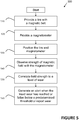
- Figure 5 is a flowchart describing one embodiment of a method 500 of detecting tread wear in a tire including at least one belt having magnetic properties.
- method 500 starts with providing a tire with a magnetic belt 510 and separately providing a magnetometer 520.
- Providing step 510 and providing step 520 may be performed concurrently or independently.
- a tire is mounted on a wheel, a vehicle having a mounted tire is provided, or a tire mounted on a wheel is presented for measurement.
- a magnetometer is presented (e.g., as a handheld sensor) to take a measurement, a magnetometer is mounted on a vehicle, or a magnetometer is provided on a floor surface.
- the magnetometer has a sensitivity of at least 0.01 mT. In another embodiment, the magnetometer has a sensitivity of at least 0.001 mT.
- a user or machine positions the tire and magnetometer 530 within proximity of each other.
- the tire is positioned by driving it over a surface that contains the magnetometer.
- the magnetometer is positioned by placing it in contact with the tire.
- the magnetometer is mounted on a car (such as in a wheel well).
- the strength of the magnetic field is measured 540 using the magnetometer.
- the measurement is displayed on the magnetometer.
- the measurement is transmitted to a digital device.
- the measurement is recorded on an RFID chip.
- the measurement is correlated 550 to a level of wear.
- the strength of the magnetic field is used to estimate the tread depth.
- Table 1, below, is an exemplary lookup table used to calculate tread wear: Magnetic Field (mT) Tread Depth (mm) 4.0 9 4.5 8 5.5 6 6.5 5 8.0 3
- the measurement from the magnetometer is compared to an initial measured value corresponding to an initial (unworn) state of the tread.
- the measurement is then processed along with the initial measured value in an algorithm, which is used to calculate the worn tread depth.
- the correlation may be used in generating 560 an alert when the tread wear has reached a predetermined threshold.
- the generating step 560 may be performed concurrently or independently of positioning step 530, measuring step 540, and correlating step 550.
- the strength of the magnetic field is compared against a predetermined threshold. If the strength of the magnetic field has reached the threshold, then an alert relating to the worn state is generated.
- a wear alert (or report) is generated at regular intervals for maintenance purposes. The alerts (or reports) can include a predication of how much longer the tread can be used.
- a wear alert (or report) is generated at regular intervals for quality assurance and performance tracking purposes.
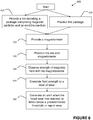
- Figure 6 is a flowchart describing one embodiment of a method for detecting tread wear in a tire including at least one package comprising magnetic particles and an erodible medium.
- the Figure 6 embodiment is substantially similar to the Figure 5 embodiment, except for the differences discussed below.
- method 600 starts with providing 610 a tire including at least one package comprising magnetic particles and an erodible medium.
- at least one package comprising magnetic particles and an erodible medium is provided within a tire tread.
- the package is provided by being placed within, or forcibly propelled into, a slot in the tread.
- the slot may be created using, without limitation, a needle, cannula, blade, pin, nail, drill, or tire mold.
- the diameter of the slot is between 80 and 120% of the diameter of the package.
- a slot may be created using 3D printing or subtractive manufacturing.
- adhesives or liquid rubber may be used to fix the package within the slot.
- the package is provided by being placed within, or forcibly propelled into, a hole.
- a hole may be created using, without limitation, a needle, cannula, blade, pin, nail, drill, tire mold, 3D printing, or subtractive manufacturing.
- the diameter of the hole is between 120 and 200% of the diameter of the package.
- adhesives or liquid rubber may be used in conjunction with providing the package within the hole.
- Method 600 then continues with positioning 620 the at least one package comprising magnetic particles and an erodible medium.
- positioning step 620 it is determined where the package(s) is/are disposed about the tread.
- the packages may be disposed according to the descriptions provided with regard to Figures 1-4 above.
- method 600 continues with providing step 520, positioning step 520, and measuring step 540.
- Method 600 then continues with correlating step 630.
- the measurement is correlated 630 to a level of wear.
- the strength of the magnetic field is used to estimate the tread depth.
- Table 2, below, is an exemplary lookup table used to calculate tread wear when magnetic particles are utilized: Magnetic Field (mT) Tread Depth (mm) 8.0 9 6.5 8 5.5 6 4.5 5 4.0 3
- Method 600 then concludes with generating step 560.
- tire embodiments described in this disclosure may be configured for use on a vehicle selected from the group consisting of motorcycles, tractors, agricultural vehicles, lawnmowers, golf carts, scooters, airplanes, military vehicles, passenger vehicles, hybrid vehicles, high-performance vehicles, sport-utility vehicles, light trucks, heavy trucks, heavy-duty vehicles, and buses.
- tread patterns including, without limitation, symmetrical, asymmetrical, directional, studded, and stud-less tread patterns.
- large tires include, but are not limited to, agricultural tires, mining tires, forestry tires, skid steer tires, construction tires, monster-truck tires, and other heavy-duty vehicle tires.
Landscapes
- Engineering & Computer Science (AREA)
- Mechanical Engineering (AREA)
- Tires In General (AREA)
- Investigating Or Analyzing Materials By The Use Of Magnetic Means (AREA)
Applications Claiming Priority (1)
| Application Number | Priority Date | Filing Date | Title |
|---|---|---|---|
| US201662434777P | 2016-12-15 | 2016-12-15 |
Publications (3)
| Publication Number | Publication Date |
|---|---|
| EP3335912A2 true EP3335912A2 (de) | 2018-06-20 |
| EP3335912A3 EP3335912A3 (de) | 2018-07-18 |
| EP3335912B1 EP3335912B1 (de) | 2019-10-30 |
Family
ID=60673557
Family Applications (1)
| Application Number | Title | Priority Date | Filing Date |
|---|---|---|---|
| EP17207273.8A Not-in-force EP3335912B1 (de) | 2016-12-15 | 2017-12-14 | Reifen mit magnetischer laufflächenerkennung |
Country Status (2)
| Country | Link |
|---|---|
| US (1) | US20180170118A1 (de) |
| EP (1) | EP3335912B1 (de) |
Cited By (3)
| Publication number | Priority date | Publication date | Assignee | Title |
|---|---|---|---|---|
| CN110871651A (zh) * | 2018-08-31 | 2020-03-10 | 点晶科技股份有限公司 | 胎纹侦测模块以及胎纹侦测装置 |
| CN111002609A (zh) * | 2018-10-05 | 2020-04-14 | 住友橡胶工业株式会社 | 充气轮胎的制造方法 |
| EP4101660A1 (de) | 2021-06-09 | 2022-12-14 | The Goodyear Tire & Rubber Company | Reifen mit magnetischem laufflächenabnutzungssensor und laufflächenabnutzungsüberwachungsverfahren |
Families Citing this family (8)
| Publication number | Priority date | Publication date | Assignee | Title |
|---|---|---|---|---|
| JP6677347B2 (ja) * | 2017-11-28 | 2020-04-08 | 横浜ゴム株式会社 | 空気入りタイヤ、タイヤ摩耗情報取得システム、及び空気入りタイヤの摩耗情報取得方法 |
| JP2019203831A (ja) * | 2018-05-25 | 2019-11-28 | 住友ゴム工業株式会社 | 空気入りタイヤ、タイヤ摩耗測定方法およびタイヤ摩耗測定システムならびにセンサモジュール |
| WO2020145012A1 (ja) * | 2019-01-09 | 2020-07-16 | アルプスアルパイン株式会社 | タイヤの摩耗測定装置 |
| WO2020154145A1 (en) * | 2019-01-22 | 2020-07-30 | Tyrata, Inc. | Tire structures including magnets and/or magnetically conductive material and related tire assemblies and tread monitoring systems |
| DE102019219669A1 (de) * | 2019-12-16 | 2021-06-17 | Continental Reifen Deutschland Gmbh | 3D-Druck von Reifenformelementen |
| US11772416B2 (en) * | 2020-10-06 | 2023-10-03 | The Goodyear Tire & Rubber Company | System for detection of non-pneumatic tire loading |
| JP7387023B2 (ja) * | 2020-10-22 | 2023-11-27 | アルプスアルパイン株式会社 | タイヤ摩耗測定装置、空気入りタイヤおよびタイヤ摩耗測定方法 |
| CN116604747B (zh) * | 2023-07-20 | 2023-09-29 | 山东豪迈机械科技股份有限公司 | 一种基于增材制造技术的模具制造方法及轮胎 |
Family Cites Families (13)
| Publication number | Priority date | Publication date | Assignee | Title |
|---|---|---|---|---|
| US20010021729A1 (en) * | 2001-02-16 | 2001-09-13 | Papp Frank P. | Incorporating high levels of magnetic particulate into the rubber matrix of rubber compounds |
| FR2816887B1 (fr) * | 2000-11-20 | 2003-03-14 | Dufournier Technologies | Procede et dispositif detecteur d'usure des pneumatiques ou bandes de roulement et surfaces ou zones d'usure analogues |
| WO2003099592A1 (en) * | 2002-05-24 | 2003-12-04 | Bridgestone Corporation | Magnetized tire |
| US7601095B2 (en) * | 2005-07-20 | 2009-10-13 | Kanzaki Kokyukoki Mfg. Co., Ltd. | Vehicle |
| US8041463B2 (en) * | 2006-05-09 | 2011-10-18 | Advanced Liquid Logic, Inc. | Modular droplet actuator drive |
| JP4877513B2 (ja) * | 2007-03-14 | 2012-02-15 | 戸田工業株式会社 | ボンド磁石用フェライト粒子粉末、ボンド磁石用樹脂組成物ならびにそれらを用いた成型体 |
| DE102008028967A1 (de) * | 2007-07-27 | 2009-02-19 | Continental Teves Ag & Co. Ohg | Verfahren zur Ermittlung der Profiltiefe eines Reifens und/oder einer Reifeneigenschaft sowie Reifen |
| US7762129B2 (en) * | 2007-09-25 | 2010-07-27 | Infineon Technologies Ag | Tire tread detection and measurement of physical variables of a tire on a moving vehicle |
| US20090114322A1 (en) * | 2007-11-06 | 2009-05-07 | O'brien Pat | Tread marker, tire with integral tread markers, and methods for producing both |
| FR3021587B1 (fr) * | 2014-05-27 | 2016-06-10 | Michelin & Cie | Pneumatique dont la zone sommet est pourvue d'une sous-couche comportant un elastomere thermoplastique et une charge magnetique |
| JP6475340B2 (ja) * | 2014-12-31 | 2019-02-27 | ブリヂストン アメリカズ タイヤ オペレーションズ、 エルエルシー | タイヤ用途のためのrfid摩耗検知 |
| DE102015207381A1 (de) * | 2015-04-22 | 2016-10-27 | Continental Reifen Deutschland Gmbh | Fahrzeugreifen mit einem Reifenmodul |
| WO2016200507A1 (en) * | 2015-06-11 | 2016-12-15 | Bridgestone Americas Tire Operations, Llc | Belt assemblies coated with a magnetic rubber composition and tires including the same |
-
2017
- 2017-12-14 EP EP17207273.8A patent/EP3335912B1/de not_active Not-in-force
- 2017-12-14 US US15/841,818 patent/US20180170118A1/en not_active Abandoned
Non-Patent Citations (1)
| Title |
|---|
| BRYAN A. GARNER, A DICTIONARY OF MODERN LEGAL USAGE, vol. 624, 1995 |
Cited By (3)
| Publication number | Priority date | Publication date | Assignee | Title |
|---|---|---|---|---|
| CN110871651A (zh) * | 2018-08-31 | 2020-03-10 | 点晶科技股份有限公司 | 胎纹侦测模块以及胎纹侦测装置 |
| CN111002609A (zh) * | 2018-10-05 | 2020-04-14 | 住友橡胶工业株式会社 | 充气轮胎的制造方法 |
| EP4101660A1 (de) | 2021-06-09 | 2022-12-14 | The Goodyear Tire & Rubber Company | Reifen mit magnetischem laufflächenabnutzungssensor und laufflächenabnutzungsüberwachungsverfahren |
Also Published As
| Publication number | Publication date |
|---|---|
| US20180170118A1 (en) | 2018-06-21 |
| EP3335912B1 (de) | 2019-10-30 |
| EP3335912A3 (de) | 2018-07-18 |
Similar Documents
| Publication | Publication Date | Title |
|---|---|---|
| EP3335912B1 (de) | Reifen mit magnetischer laufflächenerkennung | |
| US10513153B2 (en) | RFID wear sensing for tire applications | |
| US8403012B2 (en) | Tread wear indicator | |
| US11541695B2 (en) | Pneumatic tire, tire wear information acquisition system, and method for acquiring wear information of pneumatic tire | |
| US11090984B2 (en) | Sensor system for monitoring tire wear | |
| EP3240704B1 (de) | Radarverschleissmessung für reifenanwendungen | |
| US11774301B2 (en) | Tire load estimation system and method | |
| US20190193480A1 (en) | Sensor system for monitoring tire wear | |
| CN115335676B (zh) | 轮胎信息感测装置 | |
| RU2657626C1 (ru) | Пневматическая шина | |
| JP7460379B2 (ja) | 摩耗状態検知装置 | |
| JP6557996B2 (ja) | 空気入りタイヤ | |
| JP6721134B2 (ja) | タイヤ組み立て体及びタイヤ変形状態判定システム | |
| JPS5911903A (ja) | タイヤ | |
| CN115003526B (zh) | 磨耗状态感测装置 | |
| CN108025602B (zh) | 充气轮胎以及防滑钉 | |
| JP2003226120A (ja) | 空気入りタイヤ及びタイヤ変形検出方法 | |
| JP2016529479A (ja) | タイヤ用のゴム層の厚さを測定するシステム | |
| JP2024076454A (ja) | タイヤ | |
| US20080073010A1 (en) | Alerting structure for an abrasion of tire | |
| EP1902868A1 (de) | Reifenlauffläche mit farbigen Einsätzen zur Erkennung des Abriebs | |
| US20160039250A1 (en) | Tire tread depth indicator |
Legal Events
| Date | Code | Title | Description |
|---|---|---|---|
| PUAI | Public reference made under article 153(3) epc to a published international application that has entered the european phase |
Free format text: ORIGINAL CODE: 0009012 |
|
| STAA | Information on the status of an ep patent application or granted ep patent |
Free format text: STATUS: REQUEST FOR EXAMINATION WAS MADE |
|
| PUAL | Search report despatched |
Free format text: ORIGINAL CODE: 0009013 |
|
| 17P | Request for examination filed |
Effective date: 20171214 |
|
| AK | Designated contracting states |
Kind code of ref document: A2 Designated state(s): AL AT BE BG CH CY CZ DE DK EE ES FI FR GB GR HR HU IE IS IT LI LT LU LV MC MK MT NL NO PL PT RO RS SE SI SK SM TR |
|
| AX | Request for extension of the european patent |
Extension state: BA ME |
|
| AK | Designated contracting states |
Kind code of ref document: A3 Designated state(s): AL AT BE BG CH CY CZ DE DK EE ES FI FR GB GR HR HU IE IS IT LI LT LU LV MC MK MT NL NO PL PT RO RS SE SI SK SM TR |
|
| AX | Request for extension of the european patent |
Extension state: BA ME |
|
| RIC1 | Information provided on ipc code assigned before grant |
Ipc: B60C 11/24 20060101AFI20180608BHEP |
|
| RAP1 | Party data changed (applicant data changed or rights of an application transferred) |
Owner name: BRIDGESTONE AMERICAS TIRE OPERATIONS, LLC |
|
| RIC1 | Information provided on ipc code assigned before grant |
Ipc: B60C 11/24 20060101AFI20190418BHEP |
|
| GRAP | Despatch of communication of intention to grant a patent |
Free format text: ORIGINAL CODE: EPIDOSNIGR1 |
|
| STAA | Information on the status of an ep patent application or granted ep patent |
Free format text: STATUS: GRANT OF PATENT IS INTENDED |
|
| INTG | Intention to grant announced |
Effective date: 20190531 |
|
| GRAS | Grant fee paid |
Free format text: ORIGINAL CODE: EPIDOSNIGR3 |
|
| GRAA | (expected) grant |
Free format text: ORIGINAL CODE: 0009210 |
|
| STAA | Information on the status of an ep patent application or granted ep patent |
Free format text: STATUS: THE PATENT HAS BEEN GRANTED |
|
| AK | Designated contracting states |
Kind code of ref document: B1 Designated state(s): AL AT BE BG CH CY CZ DE DK EE ES FI FR GB GR HR HU IE IS IT LI LT LU LV MC MK MT NL NO PL PT RO RS SE SI SK SM TR |
|
| REG | Reference to a national code |
Ref country code: GB Ref legal event code: FG4D |
|
| REG | Reference to a national code |
Ref country code: CH Ref legal event code: EP |
|
| REG | Reference to a national code |
Ref country code: AT Ref legal event code: REF Ref document number: 1195730 Country of ref document: AT Kind code of ref document: T Effective date: 20191115 |
|
| REG | Reference to a national code |
Ref country code: DE Ref legal event code: R096 Ref document number: 602017008217 Country of ref document: DE |
|
| REG | Reference to a national code |
Ref country code: IE Ref legal event code: FG4D |
|
| PGFP | Annual fee paid to national office [announced via postgrant information from national office to epo] |
Ref country code: DE Payment date: 20191114 Year of fee payment: 3 |
|
| PGFP | Annual fee paid to national office [announced via postgrant information from national office to epo] |
Ref country code: FR Payment date: 20191122 Year of fee payment: 3 |
|
| REG | Reference to a national code |
Ref country code: LT Ref legal event code: MG4D |
|
| PG25 | Lapsed in a contracting state [announced via postgrant information from national office to epo] |
Ref country code: SE Free format text: LAPSE BECAUSE OF FAILURE TO SUBMIT A TRANSLATION OF THE DESCRIPTION OR TO PAY THE FEE WITHIN THE PRESCRIBED TIME-LIMIT Effective date: 20191030 Ref country code: LV Free format text: LAPSE BECAUSE OF FAILURE TO SUBMIT A TRANSLATION OF THE DESCRIPTION OR TO PAY THE FEE WITHIN THE PRESCRIBED TIME-LIMIT Effective date: 20191030 Ref country code: NL Free format text: LAPSE BECAUSE OF FAILURE TO SUBMIT A TRANSLATION OF THE DESCRIPTION OR TO PAY THE FEE WITHIN THE PRESCRIBED TIME-LIMIT Effective date: 20191030 Ref country code: PL Free format text: LAPSE BECAUSE OF FAILURE TO SUBMIT A TRANSLATION OF THE DESCRIPTION OR TO PAY THE FEE WITHIN THE PRESCRIBED TIME-LIMIT Effective date: 20191030 Ref country code: LT Free format text: LAPSE BECAUSE OF FAILURE TO SUBMIT A TRANSLATION OF THE DESCRIPTION OR TO PAY THE FEE WITHIN THE PRESCRIBED TIME-LIMIT Effective date: 20191030 Ref country code: FI Free format text: LAPSE BECAUSE OF FAILURE TO SUBMIT A TRANSLATION OF THE DESCRIPTION OR TO PAY THE FEE WITHIN THE PRESCRIBED TIME-LIMIT Effective date: 20191030 Ref country code: GR Free format text: LAPSE BECAUSE OF FAILURE TO SUBMIT A TRANSLATION OF THE DESCRIPTION OR TO PAY THE FEE WITHIN THE PRESCRIBED TIME-LIMIT Effective date: 20200131 Ref country code: NO Free format text: LAPSE BECAUSE OF FAILURE TO SUBMIT A TRANSLATION OF THE DESCRIPTION OR TO PAY THE FEE WITHIN THE PRESCRIBED TIME-LIMIT Effective date: 20200130 Ref country code: PT Free format text: LAPSE BECAUSE OF FAILURE TO SUBMIT A TRANSLATION OF THE DESCRIPTION OR TO PAY THE FEE WITHIN THE PRESCRIBED TIME-LIMIT Effective date: 20200302 Ref country code: BG Free format text: LAPSE BECAUSE OF FAILURE TO SUBMIT A TRANSLATION OF THE DESCRIPTION OR TO PAY THE FEE WITHIN THE PRESCRIBED TIME-LIMIT Effective date: 20200130 |
|
| REG | Reference to a national code |
Ref country code: NL Ref legal event code: MP Effective date: 20191030 |
|
| PG25 | Lapsed in a contracting state [announced via postgrant information from national office to epo] |
Ref country code: RS Free format text: LAPSE BECAUSE OF FAILURE TO SUBMIT A TRANSLATION OF THE DESCRIPTION OR TO PAY THE FEE WITHIN THE PRESCRIBED TIME-LIMIT Effective date: 20191030 Ref country code: IS Free format text: LAPSE BECAUSE OF FAILURE TO SUBMIT A TRANSLATION OF THE DESCRIPTION OR TO PAY THE FEE WITHIN THE PRESCRIBED TIME-LIMIT Effective date: 20200229 Ref country code: HR Free format text: LAPSE BECAUSE OF FAILURE TO SUBMIT A TRANSLATION OF THE DESCRIPTION OR TO PAY THE FEE WITHIN THE PRESCRIBED TIME-LIMIT Effective date: 20191030 |
|
| PG25 | Lapsed in a contracting state [announced via postgrant information from national office to epo] |
Ref country code: AL Free format text: LAPSE BECAUSE OF FAILURE TO SUBMIT A TRANSLATION OF THE DESCRIPTION OR TO PAY THE FEE WITHIN THE PRESCRIBED TIME-LIMIT Effective date: 20191030 |
|
| PG25 | Lapsed in a contracting state [announced via postgrant information from national office to epo] |
Ref country code: ES Free format text: LAPSE BECAUSE OF FAILURE TO SUBMIT A TRANSLATION OF THE DESCRIPTION OR TO PAY THE FEE WITHIN THE PRESCRIBED TIME-LIMIT Effective date: 20191030 Ref country code: DK Free format text: LAPSE BECAUSE OF FAILURE TO SUBMIT A TRANSLATION OF THE DESCRIPTION OR TO PAY THE FEE WITHIN THE PRESCRIBED TIME-LIMIT Effective date: 20191030 Ref country code: EE Free format text: LAPSE BECAUSE OF FAILURE TO SUBMIT A TRANSLATION OF THE DESCRIPTION OR TO PAY THE FEE WITHIN THE PRESCRIBED TIME-LIMIT Effective date: 20191030 Ref country code: CZ Free format text: LAPSE BECAUSE OF FAILURE TO SUBMIT A TRANSLATION OF THE DESCRIPTION OR TO PAY THE FEE WITHIN THE PRESCRIBED TIME-LIMIT Effective date: 20191030 Ref country code: RO Free format text: LAPSE BECAUSE OF FAILURE TO SUBMIT A TRANSLATION OF THE DESCRIPTION OR TO PAY THE FEE WITHIN THE PRESCRIBED TIME-LIMIT Effective date: 20191030 |
|
| REG | Reference to a national code |
Ref country code: DE Ref legal event code: R097 Ref document number: 602017008217 Country of ref document: DE |
|
| REG | Reference to a national code |
Ref country code: AT Ref legal event code: MK05 Ref document number: 1195730 Country of ref document: AT Kind code of ref document: T Effective date: 20191030 |
|
| REG | Reference to a national code |
Ref country code: BE Ref legal event code: MM Effective date: 20191231 |
|
| PG25 | Lapsed in a contracting state [announced via postgrant information from national office to epo] |
Ref country code: SM Free format text: LAPSE BECAUSE OF FAILURE TO SUBMIT A TRANSLATION OF THE DESCRIPTION OR TO PAY THE FEE WITHIN THE PRESCRIBED TIME-LIMIT Effective date: 20191030 Ref country code: IT Free format text: LAPSE BECAUSE OF FAILURE TO SUBMIT A TRANSLATION OF THE DESCRIPTION OR TO PAY THE FEE WITHIN THE PRESCRIBED TIME-LIMIT Effective date: 20191030 Ref country code: SK Free format text: LAPSE BECAUSE OF FAILURE TO SUBMIT A TRANSLATION OF THE DESCRIPTION OR TO PAY THE FEE WITHIN THE PRESCRIBED TIME-LIMIT Effective date: 20191030 Ref country code: MC Free format text: LAPSE BECAUSE OF FAILURE TO SUBMIT A TRANSLATION OF THE DESCRIPTION OR TO PAY THE FEE WITHIN THE PRESCRIBED TIME-LIMIT Effective date: 20191030 |
|
| PLBE | No opposition filed within time limit |
Free format text: ORIGINAL CODE: 0009261 |
|
| STAA | Information on the status of an ep patent application or granted ep patent |
Free format text: STATUS: NO OPPOSITION FILED WITHIN TIME LIMIT |
|
| 26N | No opposition filed |
Effective date: 20200731 |
|
| PG25 | Lapsed in a contracting state [announced via postgrant information from national office to epo] |
Ref country code: IE Free format text: LAPSE BECAUSE OF NON-PAYMENT OF DUE FEES Effective date: 20191214 Ref country code: LU Free format text: LAPSE BECAUSE OF NON-PAYMENT OF DUE FEES Effective date: 20191214 |
|
| PG25 | Lapsed in a contracting state [announced via postgrant information from national office to epo] |
Ref country code: SI Free format text: LAPSE BECAUSE OF FAILURE TO SUBMIT A TRANSLATION OF THE DESCRIPTION OR TO PAY THE FEE WITHIN THE PRESCRIBED TIME-LIMIT Effective date: 20191030 Ref country code: BE Free format text: LAPSE BECAUSE OF NON-PAYMENT OF DUE FEES Effective date: 20191231 Ref country code: AT Free format text: LAPSE BECAUSE OF FAILURE TO SUBMIT A TRANSLATION OF THE DESCRIPTION OR TO PAY THE FEE WITHIN THE PRESCRIBED TIME-LIMIT Effective date: 20191030 |
|
| PG25 | Lapsed in a contracting state [announced via postgrant information from national office to epo] |
Ref country code: CY Free format text: LAPSE BECAUSE OF FAILURE TO SUBMIT A TRANSLATION OF THE DESCRIPTION OR TO PAY THE FEE WITHIN THE PRESCRIBED TIME-LIMIT Effective date: 20191030 |
|
| REG | Reference to a national code |
Ref country code: DE Ref legal event code: R119 Ref document number: 602017008217 Country of ref document: DE |
|
| PG25 | Lapsed in a contracting state [announced via postgrant information from national office to epo] |
Ref country code: MT Free format text: LAPSE BECAUSE OF FAILURE TO SUBMIT A TRANSLATION OF THE DESCRIPTION OR TO PAY THE FEE WITHIN THE PRESCRIBED TIME-LIMIT Effective date: 20191030 Ref country code: HU Free format text: LAPSE BECAUSE OF FAILURE TO SUBMIT A TRANSLATION OF THE DESCRIPTION OR TO PAY THE FEE WITHIN THE PRESCRIBED TIME-LIMIT; INVALID AB INITIO Effective date: 20171214 |
|
| REG | Reference to a national code |
Ref country code: CH Ref legal event code: PL |
|
| PG25 | Lapsed in a contracting state [announced via postgrant information from national office to epo] |
Ref country code: FR Free format text: LAPSE BECAUSE OF NON-PAYMENT OF DUE FEES Effective date: 20201231 |
|
| PG25 | Lapsed in a contracting state [announced via postgrant information from national office to epo] |
Ref country code: DE Free format text: LAPSE BECAUSE OF NON-PAYMENT OF DUE FEES Effective date: 20210701 Ref country code: CH Free format text: LAPSE BECAUSE OF NON-PAYMENT OF DUE FEES Effective date: 20201231 Ref country code: LI Free format text: LAPSE BECAUSE OF NON-PAYMENT OF DUE FEES Effective date: 20201231 |
|
| PG25 | Lapsed in a contracting state [announced via postgrant information from national office to epo] |
Ref country code: TR Free format text: LAPSE BECAUSE OF FAILURE TO SUBMIT A TRANSLATION OF THE DESCRIPTION OR TO PAY THE FEE WITHIN THE PRESCRIBED TIME-LIMIT Effective date: 20191030 |
|
| PG25 | Lapsed in a contracting state [announced via postgrant information from national office to epo] |
Ref country code: MK Free format text: LAPSE BECAUSE OF FAILURE TO SUBMIT A TRANSLATION OF THE DESCRIPTION OR TO PAY THE FEE WITHIN THE PRESCRIBED TIME-LIMIT Effective date: 20191030 |
|
| GBPC | Gb: european patent ceased through non-payment of renewal fee |
Effective date: 20211214 |
|
| PG25 | Lapsed in a contracting state [announced via postgrant information from national office to epo] |
Ref country code: GB Free format text: LAPSE BECAUSE OF NON-PAYMENT OF DUE FEES Effective date: 20211214 |