EP3335749B1 - Mécanisme de commande pour dispositif d'administration de médicaments et dispositif d'administration de médicaments - Google Patents
Mécanisme de commande pour dispositif d'administration de médicaments et dispositif d'administration de médicaments Download PDFInfo
- Publication number
- EP3335749B1 EP3335749B1 EP18152599.9A EP18152599A EP3335749B1 EP 3335749 B1 EP3335749 B1 EP 3335749B1 EP 18152599 A EP18152599 A EP 18152599A EP 3335749 B1 EP3335749 B1 EP 3335749B1
- Authority
- EP
- European Patent Office
- Prior art keywords
- dose
- drive
- rotation
- housing
- respect
- Prior art date
- Legal status (The legal status is an assumption and is not a legal conclusion. Google has not performed a legal analysis and makes no representation as to the accuracy of the status listed.)
- Active
Links
- 230000007246 mechanism Effects 0.000 title claims description 120
- 239000003814 drug Substances 0.000 title claims description 73
- 229940079593 drug Drugs 0.000 title claims description 73
- 230000000903 blocking effect Effects 0.000 description 19
- 238000006073 displacement reaction Methods 0.000 description 19
- 230000000717 retained effect Effects 0.000 description 8
- 230000008878 coupling Effects 0.000 description 6
- 238000010168 coupling process Methods 0.000 description 6
- 238000005859 coupling reaction Methods 0.000 description 6
- 238000002347 injection Methods 0.000 description 6
- 239000007924 injection Substances 0.000 description 6
- 230000009471 action Effects 0.000 description 5
- 239000003708 ampul Substances 0.000 description 4
- 230000003993 interaction Effects 0.000 description 4
- 239000012528 membrane Substances 0.000 description 4
- 230000006835 compression Effects 0.000 description 2
- 238000007906 compression Methods 0.000 description 2
- NOESYZHRGYRDHS-UHFFFAOYSA-N insulin Chemical compound N1C(=O)C(NC(=O)C(CCC(N)=O)NC(=O)C(CCC(O)=O)NC(=O)C(C(C)C)NC(=O)C(NC(=O)CN)C(C)CC)CSSCC(C(NC(CO)C(=O)NC(CC(C)C)C(=O)NC(CC=2C=CC(O)=CC=2)C(=O)NC(CCC(N)=O)C(=O)NC(CC(C)C)C(=O)NC(CCC(O)=O)C(=O)NC(CC(N)=O)C(=O)NC(CC=2C=CC(O)=CC=2)C(=O)NC(CSSCC(NC(=O)C(C(C)C)NC(=O)C(CC(C)C)NC(=O)C(CC=2C=CC(O)=CC=2)NC(=O)C(CC(C)C)NC(=O)C(C)NC(=O)C(CCC(O)=O)NC(=O)C(C(C)C)NC(=O)C(CC(C)C)NC(=O)C(CC=2NC=NC=2)NC(=O)C(CO)NC(=O)CNC2=O)C(=O)NCC(=O)NC(CCC(O)=O)C(=O)NC(CCCNC(N)=N)C(=O)NCC(=O)NC(CC=3C=CC=CC=3)C(=O)NC(CC=3C=CC=CC=3)C(=O)NC(CC=3C=CC(O)=CC=3)C(=O)NC(C(C)O)C(=O)N3C(CCC3)C(=O)NC(CCCCN)C(=O)NC(C)C(O)=O)C(=O)NC(CC(N)=O)C(O)=O)=O)NC(=O)C(C(C)CC)NC(=O)C(CO)NC(=O)C(C(C)O)NC(=O)C1CSSCC2NC(=O)C(CC(C)C)NC(=O)C(NC(=O)C(CCC(N)=O)NC(=O)C(CC(N)=O)NC(=O)C(NC(=O)C(N)CC=1C=CC=CC=1)C(C)C)CC1=CN=CN1 NOESYZHRGYRDHS-UHFFFAOYSA-N 0.000 description 2
- 239000007788 liquid Substances 0.000 description 2
- 241000937413 Axia Species 0.000 description 1
- HTTJABKRGRZYRN-UHFFFAOYSA-N Heparin Chemical compound OC1C(NC(=O)C)C(O)OC(COS(O)(=O)=O)C1OC1C(OS(O)(=O)=O)C(O)C(OC2C(C(OS(O)(=O)=O)C(OC3C(C(O)C(O)C(O3)C(O)=O)OS(O)(=O)=O)C(CO)O2)NS(O)(=O)=O)C(C(O)=O)O1 HTTJABKRGRZYRN-UHFFFAOYSA-N 0.000 description 1
- 102000004877 Insulin Human genes 0.000 description 1
- 108090001061 Insulin Proteins 0.000 description 1
- 238000010276 construction Methods 0.000 description 1
- 239000000356 contaminant Substances 0.000 description 1
- 230000003247 decreasing effect Effects 0.000 description 1
- 230000001419 dependent effect Effects 0.000 description 1
- 230000000881 depressing effect Effects 0.000 description 1
- 238000007599 discharging Methods 0.000 description 1
- 238000012377 drug delivery Methods 0.000 description 1
- 239000000428 dust Substances 0.000 description 1
- 239000012530 fluid Substances 0.000 description 1
- 239000000122 growth hormone Substances 0.000 description 1
- 229960002897 heparin Drugs 0.000 description 1
- 229920000669 heparin Polymers 0.000 description 1
- 229940025708 injectable product Drugs 0.000 description 1
- 229940125396 insulin Drugs 0.000 description 1
- 231100000518 lethal Toxicity 0.000 description 1
- 230000001665 lethal effect Effects 0.000 description 1
- 238000004519 manufacturing process Methods 0.000 description 1
- 239000000463 material Substances 0.000 description 1
- 230000009467 reduction Effects 0.000 description 1
- 230000011218 segmentation Effects 0.000 description 1
Images


Classifications
-
- A—HUMAN NECESSITIES
- A61—MEDICAL OR VETERINARY SCIENCE; HYGIENE
- A61M—DEVICES FOR INTRODUCING MEDIA INTO, OR ONTO, THE BODY; DEVICES FOR TRANSDUCING BODY MEDIA OR FOR TAKING MEDIA FROM THE BODY; DEVICES FOR PRODUCING OR ENDING SLEEP OR STUPOR
- A61M5/00—Devices for bringing media into the body in a subcutaneous, intra-vascular or intramuscular way; Accessories therefor, e.g. filling or cleaning devices, arm-rests
- A61M5/178—Syringes
- A61M5/31—Details
- A61M5/315—Pistons; Piston-rods; Guiding, blocking or restricting the movement of the rod or piston; Appliances on the rod for facilitating dosing ; Dosing mechanisms
-
- F—MECHANICAL ENGINEERING; LIGHTING; HEATING; WEAPONS; BLASTING
- F16—ENGINEERING ELEMENTS AND UNITS; GENERAL MEASURES FOR PRODUCING AND MAINTAINING EFFECTIVE FUNCTIONING OF MACHINES OR INSTALLATIONS; THERMAL INSULATION IN GENERAL
- F16H—GEARING
- F16H25/00—Gearings comprising primarily only cams, cam-followers and screw-and-nut mechanisms
- F16H25/18—Gearings comprising primarily only cams, cam-followers and screw-and-nut mechanisms for conveying or interconverting oscillating or reciprocating motions
- F16H25/20—Screw mechanisms
- F16H25/2015—Means specially adapted for stopping actuators in the end position; Position sensing means
-
- A—HUMAN NECESSITIES
- A61—MEDICAL OR VETERINARY SCIENCE; HYGIENE
- A61M—DEVICES FOR INTRODUCING MEDIA INTO, OR ONTO, THE BODY; DEVICES FOR TRANSDUCING BODY MEDIA OR FOR TAKING MEDIA FROM THE BODY; DEVICES FOR PRODUCING OR ENDING SLEEP OR STUPOR
- A61M5/00—Devices for bringing media into the body in a subcutaneous, intra-vascular or intramuscular way; Accessories therefor, e.g. filling or cleaning devices, arm-rests
- A61M5/178—Syringes
- A61M5/31—Details
- A61M5/315—Pistons; Piston-rods; Guiding, blocking or restricting the movement of the rod or piston; Appliances on the rod for facilitating dosing ; Dosing mechanisms
- A61M5/31533—Dosing mechanisms, i.e. setting a dose
- A61M5/31545—Setting modes for dosing
- A61M5/31548—Mechanically operated dose setting member
- A61M5/3155—Mechanically operated dose setting member by rotational movement of dose setting member, e.g. during setting or filling of a syringe
- A61M5/31551—Mechanically operated dose setting member by rotational movement of dose setting member, e.g. during setting or filling of a syringe including axial movement of dose setting member
-
- A—HUMAN NECESSITIES
- A61—MEDICAL OR VETERINARY SCIENCE; HYGIENE
- A61M—DEVICES FOR INTRODUCING MEDIA INTO, OR ONTO, THE BODY; DEVICES FOR TRANSDUCING BODY MEDIA OR FOR TAKING MEDIA FROM THE BODY; DEVICES FOR PRODUCING OR ENDING SLEEP OR STUPOR
- A61M5/00—Devices for bringing media into the body in a subcutaneous, intra-vascular or intramuscular way; Accessories therefor, e.g. filling or cleaning devices, arm-rests
- A61M5/178—Syringes
- A61M5/24—Ampoule syringes, i.e. syringes with needle for use in combination with replaceable ampoules or carpules, e.g. automatic
-
- A—HUMAN NECESSITIES
- A61—MEDICAL OR VETERINARY SCIENCE; HYGIENE
- A61M—DEVICES FOR INTRODUCING MEDIA INTO, OR ONTO, THE BODY; DEVICES FOR TRANSDUCING BODY MEDIA OR FOR TAKING MEDIA FROM THE BODY; DEVICES FOR PRODUCING OR ENDING SLEEP OR STUPOR
- A61M5/00—Devices for bringing media into the body in a subcutaneous, intra-vascular or intramuscular way; Accessories therefor, e.g. filling or cleaning devices, arm-rests
- A61M5/178—Syringes
- A61M5/31—Details
- A61M5/3148—Means for causing or aiding aspiration or plunger retraction
-
- A—HUMAN NECESSITIES
- A61—MEDICAL OR VETERINARY SCIENCE; HYGIENE
- A61M—DEVICES FOR INTRODUCING MEDIA INTO, OR ONTO, THE BODY; DEVICES FOR TRANSDUCING BODY MEDIA OR FOR TAKING MEDIA FROM THE BODY; DEVICES FOR PRODUCING OR ENDING SLEEP OR STUPOR
- A61M5/00—Devices for bringing media into the body in a subcutaneous, intra-vascular or intramuscular way; Accessories therefor, e.g. filling or cleaning devices, arm-rests
- A61M5/178—Syringes
- A61M5/31—Details
- A61M5/315—Pistons; Piston-rods; Guiding, blocking or restricting the movement of the rod or piston; Appliances on the rod for facilitating dosing ; Dosing mechanisms
- A61M5/31525—Dosing
- A61M5/31528—Dosing by means of rotational movements, e.g. screw-thread mechanisms
-
- A—HUMAN NECESSITIES
- A61—MEDICAL OR VETERINARY SCIENCE; HYGIENE
- A61M—DEVICES FOR INTRODUCING MEDIA INTO, OR ONTO, THE BODY; DEVICES FOR TRANSDUCING BODY MEDIA OR FOR TAKING MEDIA FROM THE BODY; DEVICES FOR PRODUCING OR ENDING SLEEP OR STUPOR
- A61M5/00—Devices for bringing media into the body in a subcutaneous, intra-vascular or intramuscular way; Accessories therefor, e.g. filling or cleaning devices, arm-rests
- A61M5/178—Syringes
- A61M5/31—Details
- A61M5/315—Pistons; Piston-rods; Guiding, blocking or restricting the movement of the rod or piston; Appliances on the rod for facilitating dosing ; Dosing mechanisms
- A61M5/31533—Dosing mechanisms, i.e. setting a dose
- A61M5/31545—Setting modes for dosing
- A61M5/31548—Mechanically operated dose setting member
- A61M5/31555—Mechanically operated dose setting member by purely axial movement of dose setting member, e.g. during setting or filling of a syringe
-
- A—HUMAN NECESSITIES
- A61—MEDICAL OR VETERINARY SCIENCE; HYGIENE
- A61M—DEVICES FOR INTRODUCING MEDIA INTO, OR ONTO, THE BODY; DEVICES FOR TRANSDUCING BODY MEDIA OR FOR TAKING MEDIA FROM THE BODY; DEVICES FOR PRODUCING OR ENDING SLEEP OR STUPOR
- A61M5/00—Devices for bringing media into the body in a subcutaneous, intra-vascular or intramuscular way; Accessories therefor, e.g. filling or cleaning devices, arm-rests
- A61M5/178—Syringes
- A61M5/31—Details
- A61M5/315—Pistons; Piston-rods; Guiding, blocking or restricting the movement of the rod or piston; Appliances on the rod for facilitating dosing ; Dosing mechanisms
- A61M5/31565—Administration mechanisms, i.e. constructional features, modes of administering a dose
- A61M5/31576—Constructional features or modes of drive mechanisms for piston rods
- A61M5/31578—Constructional features or modes of drive mechanisms for piston rods based on axial translation, i.e. components directly operatively associated and axially moved with plunger rod
- A61M5/3158—Constructional features or modes of drive mechanisms for piston rods based on axial translation, i.e. components directly operatively associated and axially moved with plunger rod performed by axially moving actuator operated by user, e.g. an injection button
-
- A—HUMAN NECESSITIES
- A61—MEDICAL OR VETERINARY SCIENCE; HYGIENE
- A61M—DEVICES FOR INTRODUCING MEDIA INTO, OR ONTO, THE BODY; DEVICES FOR TRANSDUCING BODY MEDIA OR FOR TAKING MEDIA FROM THE BODY; DEVICES FOR PRODUCING OR ENDING SLEEP OR STUPOR
- A61M5/00—Devices for bringing media into the body in a subcutaneous, intra-vascular or intramuscular way; Accessories therefor, e.g. filling or cleaning devices, arm-rests
- A61M5/178—Syringes
- A61M5/31—Details
- A61M5/315—Pistons; Piston-rods; Guiding, blocking or restricting the movement of the rod or piston; Appliances on the rod for facilitating dosing ; Dosing mechanisms
- A61M5/31565—Administration mechanisms, i.e. constructional features, modes of administering a dose
- A61M5/31576—Constructional features or modes of drive mechanisms for piston rods
- A61M5/31578—Constructional features or modes of drive mechanisms for piston rods based on axial translation, i.e. components directly operatively associated and axially moved with plunger rod
- A61M5/31581—Constructional features or modes of drive mechanisms for piston rods based on axial translation, i.e. components directly operatively associated and axially moved with plunger rod performed by rotationally moving or pivoting actuator operated by user, e.g. an injection lever or handle
-
- A—HUMAN NECESSITIES
- A61—MEDICAL OR VETERINARY SCIENCE; HYGIENE
- A61M—DEVICES FOR INTRODUCING MEDIA INTO, OR ONTO, THE BODY; DEVICES FOR TRANSDUCING BODY MEDIA OR FOR TAKING MEDIA FROM THE BODY; DEVICES FOR PRODUCING OR ENDING SLEEP OR STUPOR
- A61M5/00—Devices for bringing media into the body in a subcutaneous, intra-vascular or intramuscular way; Accessories therefor, e.g. filling or cleaning devices, arm-rests
- A61M5/178—Syringes
- A61M5/31—Details
- A61M5/315—Pistons; Piston-rods; Guiding, blocking or restricting the movement of the rod or piston; Appliances on the rod for facilitating dosing ; Dosing mechanisms
- A61M5/31565—Administration mechanisms, i.e. constructional features, modes of administering a dose
- A61M5/31576—Constructional features or modes of drive mechanisms for piston rods
- A61M5/31583—Constructional features or modes of drive mechanisms for piston rods based on rotational translation, i.e. movement of piston rod is caused by relative rotation between the user activated actuator and the piston rod
- A61M5/31585—Constructional features or modes of drive mechanisms for piston rods based on rotational translation, i.e. movement of piston rod is caused by relative rotation between the user activated actuator and the piston rod performed by axially moving actuator, e.g. an injection button
-
- A—HUMAN NECESSITIES
- A61—MEDICAL OR VETERINARY SCIENCE; HYGIENE
- A61M—DEVICES FOR INTRODUCING MEDIA INTO, OR ONTO, THE BODY; DEVICES FOR TRANSDUCING BODY MEDIA OR FOR TAKING MEDIA FROM THE BODY; DEVICES FOR PRODUCING OR ENDING SLEEP OR STUPOR
- A61M5/00—Devices for bringing media into the body in a subcutaneous, intra-vascular or intramuscular way; Accessories therefor, e.g. filling or cleaning devices, arm-rests
- A61M5/178—Syringes
- A61M5/31—Details
- A61M5/315—Pistons; Piston-rods; Guiding, blocking or restricting the movement of the rod or piston; Appliances on the rod for facilitating dosing ; Dosing mechanisms
- A61M5/31565—Administration mechanisms, i.e. constructional features, modes of administering a dose
- A61M5/3159—Dose expelling manners
- A61M5/31593—Multi-dose, i.e. individually set dose repeatedly administered from the same medicament reservoir
-
- F—MECHANICAL ENGINEERING; LIGHTING; HEATING; WEAPONS; BLASTING
- F16—ENGINEERING ELEMENTS AND UNITS; GENERAL MEASURES FOR PRODUCING AND MAINTAINING EFFECTIVE FUNCTIONING OF MACHINES OR INSTALLATIONS; THERMAL INSULATION IN GENERAL
- F16H—GEARING
- F16H25/00—Gearings comprising primarily only cams, cam-followers and screw-and-nut mechanisms
- F16H25/08—Gearings comprising primarily only cams, cam-followers and screw-and-nut mechanisms for interconverting rotary motion and reciprocating motion
- F16H25/12—Gearings comprising primarily only cams, cam-followers and screw-and-nut mechanisms for interconverting rotary motion and reciprocating motion with reciprocation along the axis of rotation, e.g. gearings with helical grooves and automatic reversal or cams
-
- F—MECHANICAL ENGINEERING; LIGHTING; HEATING; WEAPONS; BLASTING
- F16—ENGINEERING ELEMENTS AND UNITS; GENERAL MEASURES FOR PRODUCING AND MAINTAINING EFFECTIVE FUNCTIONING OF MACHINES OR INSTALLATIONS; THERMAL INSULATION IN GENERAL
- F16H—GEARING
- F16H25/00—Gearings comprising primarily only cams, cam-followers and screw-and-nut mechanisms
- F16H25/18—Gearings comprising primarily only cams, cam-followers and screw-and-nut mechanisms for conveying or interconverting oscillating or reciprocating motions
- F16H25/20—Screw mechanisms
-
- F—MECHANICAL ENGINEERING; LIGHTING; HEATING; WEAPONS; BLASTING
- F16—ENGINEERING ELEMENTS AND UNITS; GENERAL MEASURES FOR PRODUCING AND MAINTAINING EFFECTIVE FUNCTIONING OF MACHINES OR INSTALLATIONS; THERMAL INSULATION IN GENERAL
- F16H—GEARING
- F16H31/00—Other gearings with freewheeling members or other intermittently driving members
- F16H31/001—Mechanisms with freewheeling members
-
- A—HUMAN NECESSITIES
- A61—MEDICAL OR VETERINARY SCIENCE; HYGIENE
- A61M—DEVICES FOR INTRODUCING MEDIA INTO, OR ONTO, THE BODY; DEVICES FOR TRANSDUCING BODY MEDIA OR FOR TAKING MEDIA FROM THE BODY; DEVICES FOR PRODUCING OR ENDING SLEEP OR STUPOR
- A61M5/00—Devices for bringing media into the body in a subcutaneous, intra-vascular or intramuscular way; Accessories therefor, e.g. filling or cleaning devices, arm-rests
- A61M5/178—Syringes
- A61M5/24—Ampoule syringes, i.e. syringes with needle for use in combination with replaceable ampoules or carpules, e.g. automatic
- A61M2005/2403—Ampoule inserted into the ampoule holder
- A61M2005/2407—Ampoule inserted into the ampoule holder from the rear
-
- A—HUMAN NECESSITIES
- A61—MEDICAL OR VETERINARY SCIENCE; HYGIENE
- A61M—DEVICES FOR INTRODUCING MEDIA INTO, OR ONTO, THE BODY; DEVICES FOR TRANSDUCING BODY MEDIA OR FOR TAKING MEDIA FROM THE BODY; DEVICES FOR PRODUCING OR ENDING SLEEP OR STUPOR
- A61M5/00—Devices for bringing media into the body in a subcutaneous, intra-vascular or intramuscular way; Accessories therefor, e.g. filling or cleaning devices, arm-rests
- A61M5/178—Syringes
- A61M5/31—Details
- A61M5/315—Pistons; Piston-rods; Guiding, blocking or restricting the movement of the rod or piston; Appliances on the rod for facilitating dosing ; Dosing mechanisms
- A61M5/31511—Piston or piston-rod constructions, e.g. connection of piston with piston-rod
- A61M2005/3152—Piston or piston-rod constructions, e.g. connection of piston with piston-rod including gearings to multiply or attenuate the piston displacing force
-
- A—HUMAN NECESSITIES
- A61—MEDICAL OR VETERINARY SCIENCE; HYGIENE
- A61M—DEVICES FOR INTRODUCING MEDIA INTO, OR ONTO, THE BODY; DEVICES FOR TRANSDUCING BODY MEDIA OR FOR TAKING MEDIA FROM THE BODY; DEVICES FOR PRODUCING OR ENDING SLEEP OR STUPOR
- A61M2205/00—General characteristics of the apparatus
- A61M2205/58—Means for facilitating use, e.g. by people with impaired vision
- A61M2205/581—Means for facilitating use, e.g. by people with impaired vision by audible feedback
-
- A—HUMAN NECESSITIES
- A61—MEDICAL OR VETERINARY SCIENCE; HYGIENE
- A61M—DEVICES FOR INTRODUCING MEDIA INTO, OR ONTO, THE BODY; DEVICES FOR TRANSDUCING BODY MEDIA OR FOR TAKING MEDIA FROM THE BODY; DEVICES FOR PRODUCING OR ENDING SLEEP OR STUPOR
- A61M2205/00—General characteristics of the apparatus
- A61M2205/58—Means for facilitating use, e.g. by people with impaired vision
- A61M2205/582—Means for facilitating use, e.g. by people with impaired vision by tactile feedback
-
- A—HUMAN NECESSITIES
- A61—MEDICAL OR VETERINARY SCIENCE; HYGIENE
- A61M—DEVICES FOR INTRODUCING MEDIA INTO, OR ONTO, THE BODY; DEVICES FOR TRANSDUCING BODY MEDIA OR FOR TAKING MEDIA FROM THE BODY; DEVICES FOR PRODUCING OR ENDING SLEEP OR STUPOR
- A61M5/00—Devices for bringing media into the body in a subcutaneous, intra-vascular or intramuscular way; Accessories therefor, e.g. filling or cleaning devices, arm-rests
- A61M5/178—Syringes
- A61M5/31—Details
- A61M5/315—Pistons; Piston-rods; Guiding, blocking or restricting the movement of the rod or piston; Appliances on the rod for facilitating dosing ; Dosing mechanisms
- A61M5/31511—Piston or piston-rod constructions, e.g. connection of piston with piston-rod
- A61M5/31515—Connection of piston with piston rod
-
- A—HUMAN NECESSITIES
- A61—MEDICAL OR VETERINARY SCIENCE; HYGIENE
- A61M—DEVICES FOR INTRODUCING MEDIA INTO, OR ONTO, THE BODY; DEVICES FOR TRANSDUCING BODY MEDIA OR FOR TAKING MEDIA FROM THE BODY; DEVICES FOR PRODUCING OR ENDING SLEEP OR STUPOR
- A61M5/00—Devices for bringing media into the body in a subcutaneous, intra-vascular or intramuscular way; Accessories therefor, e.g. filling or cleaning devices, arm-rests
- A61M5/178—Syringes
- A61M5/31—Details
- A61M5/315—Pistons; Piston-rods; Guiding, blocking or restricting the movement of the rod or piston; Appliances on the rod for facilitating dosing ; Dosing mechanisms
- A61M5/31533—Dosing mechanisms, i.e. setting a dose
- A61M5/31535—Means improving security or handling thereof, e.g. blocking means, means preventing insufficient dosing, means allowing correction of overset dose
- A61M5/31536—Blocking means to immobilize a selected dose, e.g. to administer equal doses
-
- A—HUMAN NECESSITIES
- A61—MEDICAL OR VETERINARY SCIENCE; HYGIENE
- A61M—DEVICES FOR INTRODUCING MEDIA INTO, OR ONTO, THE BODY; DEVICES FOR TRANSDUCING BODY MEDIA OR FOR TAKING MEDIA FROM THE BODY; DEVICES FOR PRODUCING OR ENDING SLEEP OR STUPOR
- A61M5/00—Devices for bringing media into the body in a subcutaneous, intra-vascular or intramuscular way; Accessories therefor, e.g. filling or cleaning devices, arm-rests
- A61M5/178—Syringes
- A61M5/31—Details
- A61M5/315—Pistons; Piston-rods; Guiding, blocking or restricting the movement of the rod or piston; Appliances on the rod for facilitating dosing ; Dosing mechanisms
- A61M5/31533—Dosing mechanisms, i.e. setting a dose
- A61M5/31535—Means improving security or handling thereof, e.g. blocking means, means preventing insufficient dosing, means allowing correction of overset dose
- A61M5/31541—Means preventing setting of a dose beyond the amount remaining in the cartridge
-
- A—HUMAN NECESSITIES
- A61—MEDICAL OR VETERINARY SCIENCE; HYGIENE
- A61M—DEVICES FOR INTRODUCING MEDIA INTO, OR ONTO, THE BODY; DEVICES FOR TRANSDUCING BODY MEDIA OR FOR TAKING MEDIA FROM THE BODY; DEVICES FOR PRODUCING OR ENDING SLEEP OR STUPOR
- A61M5/00—Devices for bringing media into the body in a subcutaneous, intra-vascular or intramuscular way; Accessories therefor, e.g. filling or cleaning devices, arm-rests
- A61M5/178—Syringes
- A61M5/31—Details
- A61M5/315—Pistons; Piston-rods; Guiding, blocking or restricting the movement of the rod or piston; Appliances on the rod for facilitating dosing ; Dosing mechanisms
- A61M5/31533—Dosing mechanisms, i.e. setting a dose
- A61M5/31535—Means improving security or handling thereof, e.g. blocking means, means preventing insufficient dosing, means allowing correction of overset dose
- A61M5/31543—Means improving security or handling thereof, e.g. blocking means, means preventing insufficient dosing, means allowing correction of overset dose piston rod reset means, i.e. means for causing or facilitating retraction of piston rod to its starting position during cartridge change
-
- A—HUMAN NECESSITIES
- A61—MEDICAL OR VETERINARY SCIENCE; HYGIENE
- A61M—DEVICES FOR INTRODUCING MEDIA INTO, OR ONTO, THE BODY; DEVICES FOR TRANSDUCING BODY MEDIA OR FOR TAKING MEDIA FROM THE BODY; DEVICES FOR PRODUCING OR ENDING SLEEP OR STUPOR
- A61M5/00—Devices for bringing media into the body in a subcutaneous, intra-vascular or intramuscular way; Accessories therefor, e.g. filling or cleaning devices, arm-rests
- A61M5/178—Syringes
- A61M5/31—Details
- A61M5/315—Pistons; Piston-rods; Guiding, blocking or restricting the movement of the rod or piston; Appliances on the rod for facilitating dosing ; Dosing mechanisms
- A61M5/31533—Dosing mechanisms, i.e. setting a dose
- A61M5/31545—Setting modes for dosing
- A61M5/31548—Mechanically operated dose setting member
- A61M5/31556—Accuracy improving means
- A61M5/31558—Accuracy improving means using scaling up or down transmissions, e.g. gearbox
-
- A—HUMAN NECESSITIES
- A61—MEDICAL OR VETERINARY SCIENCE; HYGIENE
- A61M—DEVICES FOR INTRODUCING MEDIA INTO, OR ONTO, THE BODY; DEVICES FOR TRANSDUCING BODY MEDIA OR FOR TAKING MEDIA FROM THE BODY; DEVICES FOR PRODUCING OR ENDING SLEEP OR STUPOR
- A61M5/00—Devices for bringing media into the body in a subcutaneous, intra-vascular or intramuscular way; Accessories therefor, e.g. filling or cleaning devices, arm-rests
- A61M5/178—Syringes
- A61M5/31—Details
- A61M5/315—Pistons; Piston-rods; Guiding, blocking or restricting the movement of the rod or piston; Appliances on the rod for facilitating dosing ; Dosing mechanisms
- A61M5/31533—Dosing mechanisms, i.e. setting a dose
- A61M5/31545—Setting modes for dosing
- A61M5/31548—Mechanically operated dose setting member
- A61M5/3156—Mechanically operated dose setting member using volume steps only adjustable in discrete intervals, i.e. individually distinct intervals
-
- A—HUMAN NECESSITIES
- A61—MEDICAL OR VETERINARY SCIENCE; HYGIENE
- A61M—DEVICES FOR INTRODUCING MEDIA INTO, OR ONTO, THE BODY; DEVICES FOR TRANSDUCING BODY MEDIA OR FOR TAKING MEDIA FROM THE BODY; DEVICES FOR PRODUCING OR ENDING SLEEP OR STUPOR
- A61M5/00—Devices for bringing media into the body in a subcutaneous, intra-vascular or intramuscular way; Accessories therefor, e.g. filling or cleaning devices, arm-rests
- A61M5/178—Syringes
- A61M5/31—Details
- A61M5/315—Pistons; Piston-rods; Guiding, blocking or restricting the movement of the rod or piston; Appliances on the rod for facilitating dosing ; Dosing mechanisms
- A61M5/31533—Dosing mechanisms, i.e. setting a dose
- A61M5/31545—Setting modes for dosing
- A61M5/31548—Mechanically operated dose setting member
- A61M5/31561—Mechanically operated dose setting member using freely adjustable volume steps
-
- A—HUMAN NECESSITIES
- A61—MEDICAL OR VETERINARY SCIENCE; HYGIENE
- A61M—DEVICES FOR INTRODUCING MEDIA INTO, OR ONTO, THE BODY; DEVICES FOR TRANSDUCING BODY MEDIA OR FOR TAKING MEDIA FROM THE BODY; DEVICES FOR PRODUCING OR ENDING SLEEP OR STUPOR
- A61M5/00—Devices for bringing media into the body in a subcutaneous, intra-vascular or intramuscular way; Accessories therefor, e.g. filling or cleaning devices, arm-rests
- A61M5/178—Syringes
- A61M5/31—Details
- A61M5/315—Pistons; Piston-rods; Guiding, blocking or restricting the movement of the rod or piston; Appliances on the rod for facilitating dosing ; Dosing mechanisms
- A61M5/31565—Administration mechanisms, i.e. constructional features, modes of administering a dose
- A61M5/31566—Means improving security or handling thereof
- A61M5/3157—Means providing feedback signals when administration is completed
-
- A—HUMAN NECESSITIES
- A61—MEDICAL OR VETERINARY SCIENCE; HYGIENE
- A61M—DEVICES FOR INTRODUCING MEDIA INTO, OR ONTO, THE BODY; DEVICES FOR TRANSDUCING BODY MEDIA OR FOR TAKING MEDIA FROM THE BODY; DEVICES FOR PRODUCING OR ENDING SLEEP OR STUPOR
- A61M5/00—Devices for bringing media into the body in a subcutaneous, intra-vascular or intramuscular way; Accessories therefor, e.g. filling or cleaning devices, arm-rests
- A61M5/178—Syringes
- A61M5/31—Details
- A61M5/315—Pistons; Piston-rods; Guiding, blocking or restricting the movement of the rod or piston; Appliances on the rod for facilitating dosing ; Dosing mechanisms
- A61M5/31565—Administration mechanisms, i.e. constructional features, modes of administering a dose
- A61M5/31566—Means improving security or handling thereof
- A61M5/31573—Accuracy improving means
- A61M5/31575—Accuracy improving means using scaling up or down transmissions, e.g. gearbox
-
- Y—GENERAL TAGGING OF NEW TECHNOLOGICAL DEVELOPMENTS; GENERAL TAGGING OF CROSS-SECTIONAL TECHNOLOGIES SPANNING OVER SEVERAL SECTIONS OF THE IPC; TECHNICAL SUBJECTS COVERED BY FORMER USPC CROSS-REFERENCE ART COLLECTIONS [XRACs] AND DIGESTS
- Y10—TECHNICAL SUBJECTS COVERED BY FORMER USPC
- Y10T—TECHNICAL SUBJECTS COVERED BY FORMER US CLASSIFICATION
- Y10T74/00—Machine element or mechanism
- Y10T74/18—Mechanical movements
- Y10T74/18568—Reciprocating or oscillating to or from alternating rotary
- Y10T74/18576—Reciprocating or oscillating to or from alternating rotary including screw and nut
- Y10T74/18696—Reciprocating or oscillating to or from alternating rotary including screw and nut including means to selectively transmit power [e.g., clutch, etc.]
Definitions
- the present invention relates to a drive mechanism for a medication delivery device and a medication delivery device incorporating such a drive mechanism.
- a piston within a cartridge that contains medication may be displaced with respect to the cartridge in the distal direction by a piston rod which moves in the distal direction with respect to the cartridge. Thereby, a dose of medication can be expelled from the cartridge.
- a medication delivery device is described in US 2007/0123829 A1 , for example.
- US 2004/0068236 A1 discloses an injection device comprising a dose and injection mechanism insertable into a housing.
- a toothed rack of an injection button engages a coupling ring wheel through a slot in a rod guiding part.
- the coupling ring wheel is integral with a coupling ring and the coupling ring engages a driver. This engagement is obtained by one or more barbs located on an inside surface of the coupling ring engaging the outer toothing of the driver.
- US 2004/0068236 A1 discloses the features of the preamble of claim 1.
- a user pulls a drive sleeve in a proximal direction away from a main housing part.
- a piston rod is prevented from moving proximally.
- the proximal travel of the drive sleeve is limited by guide slots of the internal housing to a distance corresponding to essentially one thread pitch of a helical thread of the drive sleeve.
- a second thread of the piston rod engages with a helical thread under the action of flexible arms of the piston rod.
- the user When the dose has been set, the user then dispenses the dose by depressing a dispensing face of the drive sleeve. By this action, the drive sleeve is moved axially in the distal direction. As the second thread of the piston rod is positively engaged with the helical thread of the drive sleeve, the piston rod is caused to rotate with respect to the internal housing by the axial movement.
- US 1,718,596 A teaches a hypodermic syringe.
- a trigger is moved to move a pawl, a ratchet, and a gear. This action will move a plunger rod forward within the barrel.
- a head thereof will engage a stopper of the ampule and force it forward a tapered end of the ampule for injection.
- a drive mechanism for a medication delivery device comprises a housing having a proximal end and a distal end, a rotation member which is adapted to be rotated in a first direction with respect to the housing during setting of a dose of a medication and to be rotated in a second direction with respect to the housing during delivery of the dose, the second direction being opposite to the first direction.
- the drive mechanism comprises a piston rod which is adapted to be displaced in a distal direction with respect to the housing for delivering the dose, a drive member which follows rotational movement of the rotation member in the second direction during delivery of the dose, and a stop member which prevents rotational movement of the drive member with respect to the housing in the first direction during setting of the dose, wherein the rotational movement of the drive member in the second direction is converted into movement of the piston rod in the distal direction with respect to the housing, in particular by means of mechanical cooperation of drive member and rotation member.
- the drive member may be coupled to the piston rod so as to convert its rotational movement in the second direction into distal movement of the piston rod with respect to the housing.
- the drive member may (also) be coupled to the piston rod so as to convert its rotational movement in the first direction with respect to the housing into proximal movement of the piston rod with respect to the housing.
- the risk of the piston rod being moved in the proximal direction during dose setting can be reduced by preventing rotational movement of the drive member in the first direction during setting of the dose due to provision of the stop member. Unintentional proximal movement of the piston rod may result in decreased dose accuracy. Consequently, dose accuracy may be improved by preventing (any) rotation of the drive member with respect to the housing during dose setting.
- the drive member and the rotation member are rotatable around a common rotation axis.
- the piston rod is displaced in the distal direction with respect to the housing along the rotation axis.
- the rotation axis may run along the piston rod and, in particular, along a main direction of extent of the piston rod.
- the piston rod may be splined or rotationally locked to the drive member.
- the piston rod may be threadedly coupled to the housing to convert rotational movement of the piston rod into (axial) displacement of the piston rod with respect to the housing.
- the piston rod is displaced in the distal direction with respect to the housing transversally with respect to the rotation axis.
- the rotation axis may, in particular, run transversally, for example perpendicularly, with respect to a displacement axis along which the piston rod is displaced in the distal direction with respect to the housing and, in particular, with respect to the drive member.
- the displacement axis may run along the piston rod and, in particular, along a main direction of extent of the piston rod.
- the drive mechanism comprises a dose member.
- the dose member is preferably movable with respect to the housing during setting and/or delivery of the dose.
- the dose member may be movable in the proximal direction with respect to the housing for setting the dose.
- the dose member may be movable in the distal direction with respect to the housing for delivering the set dose. Movement of the dose member with respect to the housing may be converted into rotational movement of the rotation member with respect to the housing. Movement of the dose member for setting the dose may be converted into rotational movement of the rotation member with respect to the housing in the first direction. Movement of the dose member for delivering the set dose may be converted into rotational movement of the rotation member with respect to the housing in the second direction.
- the dose member may be secured against rotational movement with respect to the housing.
- the dose member may be splined to the housing, for example.
- the dose member may be movable with respect to the rotation member. Movement of the dose member with respect to the rotation member may be converted into rotational movement of the rotation member.
- the dose member and the rotation member are engaged, preferably permanently engaged.
- Rotational movement of the rotation member may be achieved by the engagement which may convert (linear) movement of the dose member into rotational movement of the rotation member with respect to the housing.
- the dose member and the rotation member are coupled to one another via or (immediately) by a lever.
- the lever may be pivotally around the rotation axis during movement of the dose member for setting and/or delivery of the dose.
- the lever may be pivotally around the rotation axis in the first direction during movement of the dose member for setting of the dose.
- the lever may be pivotally around the rotation axis in the second direction during movement of the dose member for delivering the dose.
- the drive member preferably permanently, abuts and/or engages one of or both of stop member and rotation member during (rotational) movement of the rotation member for setting and delivery of the dose.
- the drive member may be coupled to stop member and/or rotation member during setting and delivery of the dose.
- the drive member is arranged between the stop member and the rotation member.
- the rotation member and the drive member and/or the stop member and the drive member are held in abutment by a force provided by a resilient member, in particular a spring member, during setting and delivery of the dose, in particular during rotational movement of the rotation member in the first direction and in the second direction.
- a resilient member in particular a spring member
- the rotation member and the stop member are held in abutment with the drive member by the force provided by the spring member during setting and delivery of the dose.
- the drive member and the rotation member are coupled, preferably permanently, to one another by a (first) unidirectional friction clutch mechanism.
- This friction clutch mechanism may be configured to permit relative rotational movement between rotation member and drive member during movement of the rotation member for setting of the dose and to prevent relative rotational movement of rotation member and drive member during movement of the rotation member for delivery of the dose.
- the drive member and the stop member are coupled, preferably permanently, to one another by a (second) uni-directional friction clutch mechanism.
- This friction clutch mechanism may be configured to prevent relative rotational movement between stop member and drive member during movement of the rotation member for setting of the dose and to permit relative rotational movement of stop member and drive member during movement of the rotation member for delivery of the dose.
- the stop member is secured against rotational movement with respect to the housing.
- the stop member may be displaceable along the rotation axis with respect to the housing.
- the rotation member may be secured against displacement with respect to the housing.
- the rotation member is displaceable with respect to the housing.
- the stop member may be secured against rotation and displacement with respect to the housing.
- the rotation member may be displaceable with respect to the housing, in this case.
- the spring member abuts the stop member or is integrated in the stop member.
- the drive member, the stop member, the rotation member and/or the dose member may be formed as or may comprise a sleeve.
- a rod, for example an axis rod which defines the rotation axis may extend through one of, more of or all of drive sleeve, stop sleeve, rotation sleeve and dose sleeve.
- the drive member engages the piston rod.
- the drive member is splined to the piston rod.
- the rotational movement of the drive member in the second direction is converted into rotational movement of the piston rod with respect to the housing, in particular rotational movement in the same direction and/or by the same angle, and movement of the piston rod with respect to the housing in the distal direction.
- the piston rod may be threadedly coupled to the housing, in particular threadedly engaged with the housing, for this purpose.
- the rotational movement of the drive member is converted into pure linear movement of the piston rod in the distal direction.
- the piston rod may be moved in the distal direction without rotating with respect to the housing.
- the drive member it is particularly suitable for the drive member to comprise (radial) gear teeth for engaging the piston rod, for this purpose.
- one of the drive member, the dose member, the rotation member, the stop member and the clutch member is different from one of, more of or all of the other recited members. This, separate members may be provided for fulfilling different functions.
- a medication delivery device that comprises a drive mechanism as described above.
- the device furthermore comprises a cartridge that comprises a plurality of doses of a medication.
- a piston may be arranged within the cartridge, the piston being displaceable in the distal direction with respect to the cartridge for delivering a dose of medication from the cartridge.
- the piston rod may be arranged to drive the piston in the distal direction with respect to the cartridge.
- the cartridge may be attached, permanently or releasably, to the housing.
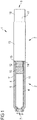
- a medication delivery device 1 comprises a cartridge unit 2 and a drive unit 3.
- the cartridge unit 2 comprises a cartridge 4.
- Medication 5 is retained in the cartridge 4.
- the medication 5 is preferably liquid medication.
- the cartridge 4 preferably comprises a plurality of doses of the medication 5.
- the medication 5 may comprise insulin, heparin, or growth hormones, for example.
- the cartridge 4 has an outlet 6 at its distal end. Medication 5 can be dispensed from the cartridge through outlet 6.
- the device 1 may be a pen-type device, in particular a pen-type injector.
- the device 1 may be a disposable or a reusable device.
- the device 1 may be a device configured to dispense fixed doses of the medication or variable, preferably user-settable, doses.
- the device 1 may be a needle-based or a needle free device.
- the device 1 may be an injection device.
- distal end of the medication delivery device 1 or a component thereof may refer to that end of the device or the component which is closest to the dispensing end of the device 1.
- proximal end of the medication delivery device 1 or a component thereof may refer to that end of the device or the component which is furthest away from the dispensing end of the device.
- distal end of the device 1 was assigned reference numeral 7 and the proximal end of the device was assigned reference numeral 8.
- the outlet 6 may be covered by a membrane 9, which protects medication 5 against external influences during storage of the cartridge.
- membrane 9 may be opened, e.g. pierced.
- membrane 9 may be pierced by a needle unit (not explicitly shown).
- the needle unit may be (releasably) attached to the distal end of the cartridge unit 2.
- the needle unit may provide for fluid communication from the inside of the cartridge 4 to the outside of the cartridge through outlet 6.
- a piston 10 is retained within the cartridge 4.
- the piston 10 is movable with respect to the cartridge.
- the piston 10 may seal the medication 5 within the cartridge.
- the piston 10 expediently seals the interior of the cartridge 4 proximally. Movement of the piston 10 with respect to the cartridge 4 in the distal direction causes medication 5 to be dispensed from the cartridge through outlet 6 during operation of the device.
- the cartridge unit 2 furthermore comprises a cartridge retaining member 11.
- the cartridge 4 is retained within the cartridge retaining member 11.
- the cartridge retaining member 11 may stabilize the cartridge 4 mechanically. Additionally or alternatively, the cartridge retaining member 11 may be provided with a fixing member (not explicitly shown) for attaching the cartridge unit 2 to the drive unit 3.
- the cartridge unit 2 and the drive unit 3 are secured to one another, preferably releasably secured.
- a cartridge unit 2 which is releasably secured to the drive unit may be detached from the drive unit 3, for example in order to allow for providing for a new cartridge 4, if all of the doses of medication which once were in the cartridge formerly attached to the drive unit 3 have already been dispensed.
- the cartridge retaining member 11 may be releasably secured to the drive unit 3 via a thread, for example.
- the cartridge retaining member 11 may be dispensed with. It is particularly expedient, in this case, to apply a robust cartridge 4 and to attach the cartridge directly to the drive unit 3.
- the drive unit 3 is configured for transferring force, preferably user-exerted force, particularly preferably manually exerted force, to the piston 10 for displacing the piston 10 with respect to the cartridge 4 in the distal direction.
- a dose of medication may be dispensed from the cartridge in this way.
- the size of the delivered dose may be determined by the distance by which the piston 10 is displaced with respect to the cartridge 4 in the distal direction.
- the drive unit 3 comprises a drive mechanism.
- the drive mechanism comprises a piston rod 12.
- the piston rod 12 may be configured for transferring force to the piston 10, thereby displacing the piston in the distal direction with respect to the cartridge 4.
- a distal end face of the piston rod 12 may be arranged to abut a proximal end face of the piston 10.
- a bearing member (not explicitly shown) may be arranged to advance the piston 10, preferably to abut the proximal end face of the piston 10.
- the bearing member may be arranged between piston 10 and piston rod 12.
- the bearing member may be fixed to the piston rod 12 or a separate member. If the piston rod 12 is configured to be rotated during operation of the device, for example during dose delivery, it is particularly expedient to provide for a bearing member.
- the bearing member may be displaced together with the (rotating) piston rod with respect to the housing.
- the piston rod may be rotatable with respect to the bearing member. In this way, the risk that the rotating piston rod drills into the piston and thereby damages the piston is reduced. Accordingly, while the piston rotates and is displaced with respect to the housing, the bearing member is preferably only displaced, i.e. does not rotate.
- the piston rod may be bounded by the bearing member.
- the drive unit 3 comprises a housing 13 which may be part of the drive mechanism.
- the piston rod 12 may be retained in the housing.
- a proximal end side 14 of the cartridge unit 2 may be secured to the drive unit 3 at a distal end side 15 of the housing 13, for example via a threaded connection.
- Housing 13, cartridge 4 and/or cartridge retaining member 11 may have a tubular shape.
- housing shall preferably mean any exterior housing ("main housing”, “body”, “shell”) or interior housing ("insert”, “inner body”) which may have a unidirectional axial coupling to prevent proximal movement of specific components.
- the housing may be designed to enable the safe, correct, and comfortable handling of the medication delivery device or any of its mechanism. Usually, it is designed to house, fix, protect, guide, and/or engage with any of the inner components of the medication delivery device (e.g., the drive mechanism, cartridge, piston, piston rod), preferably by limiting the exposure to contaminants, such as liquid, dust, dirt etc.
- the housing may be unitary or a multipart component of tubular or non-tubular shape.
- piston rod shall preferably mean a component adapted to operate through/within the housing, which may be designed to transfer axial movement through/within the medication delivery device, preferably from the drive member to the piston, for example for the purpose of discharging/dispensing an injectable product.
- Said piston rod may be flexible or not. It may be a simple rod, a lead-screw, a rack and pinion system, a worm gear system, or the like.
- “piston rod” shall further mean a component having a circular or non-circular cross-section. It may be made of any suitable material known by a person skilled in the art and may be of unitary or multipart construction.
- the drive unit 3 comprises a dose part 16.
- the dose part 16 is movable with respect to the housing 13.
- the dose part 16 may be movable in the proximal direction with respect to the housing for setting of a dose of the medication 5 which is to be delivered and in the distal direction with respect to the housing for delivery of the set dose.
- the dose part 16 is preferably connected to the housing 13.
- the dose part 16 may be secured against rotational movement with respect to the housing.
- the dose part 16 may be moved (displaced) between a proximal end position and a distal end position with respect to the housing 13 (not explicitly shown). The distance by which the dose part is displaced with respect to the housing during setting of the dose may determine a size of the dose.
- the proximal end position and the distal end position may be determined by a respective stop feature which may limit the proximal ordistal travel of the dose member with respect to the housing.
- the device 1 may be a variable dose device, i.e. a device configured for delivering doses of medication of different, preferably user-settable, sizes. Alternatively, the device may be a fixed dose device.
- the device 1 may be a manually, in particular non-electrically, driven device.
- the (user-applied) force which causes the dose part 16 to be moved with respect to the housing 13 in the distal direction may be transferred to the piston rod 12 by the drive mechanism.
- other elements of the drive mechanism may be provided which are not explicitly shown in Figure 1 .
- the drive mechanism is preferably configured to not move the piston rod 12 with respect to the housing 13 when the dose part is moved in the proximal direction with respect to the housing for setting of the dose.
- Embodiments of a drive mechanism which are suitable to be provided in the medication delivery device 1 as it was described above are described in more detail below.
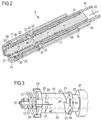
- a first embodiment of a drive mechanism which is suitable for being implemented in the medication delivery device 1 as described above is described in connection with Figures 2 to 9 .
- the drive mechanism comprises a housing part 17.
- the housing part 17 has a proximal end 18 and a distal end 19.
- the housing part 17 may be (outer) housing 13 of Figure 1 , a part thereof or an insert within housing 13, which insert is preferably secured against rotational and axial movement with respect to housing 13.
- the housing part 17 may be an insert sleeve, for example.
- the insert sleeve may be snap-fitted or glued to housing 13, for example.
- the housing part 17 may have a tubular shape.
- Housing part 17 may comprise outer fixing elements 64, for example snap-fit elements, for fixing housing part 17 to housing 13 (cf. Figure 8 ).
- the piston rod 12 is retained in the housing 13, preferably within housing part 17.
- the piston rod 12 is driven in the distal direction with respect to the housing part 17 during dose delivery.
- the drive mechanism furthermore comprises a drive member 20.
- Drive member 20 is retained within the housing part 17.
- Drive member 20 is configured to transfer force, preferably torque, to the piston rod 12. The transferred force may cause the piston rod 12 to be displaced in the distal direction with respect to the housing part 17 for dose delivery.
- Drive member 20 is rotatable with respect to housing part 17.
- the drive member 20 may engage the piston rod 12.
- Rotational movement of the drive member for example rotational movement in a second direction may be converted into distal movement of the piston rod 12 with respect to the housing part 17. This is explained in more detail below.
- the drive mechanism furthermore comprises a rotation member 21.
- the rotation member 21 is rotatable with respect to the housing part 17 in a first direction, in particular for setting of a dose of the medication, and in a second direction, in particular for delivering the set dose.
- the second direction is opposite to the first direction.
- the first direction may be counter-clockwise and the second direction may be clockwise as seen from the proximal end of the device, for example.
- Drive member, rotation member and/or piston rod are preferably configured to be rotatable about a (common) rotation axis.
- the rotation axis may extend through drive member, rotation member and/or piston rod.
- the rotation axis may be the main longitudinal axis of the piston rod.
- the rotation axis may run between the proximal end and the distal end of the housing part 17.
- the rotation member 21 is coupled to the drive member 20 by an uni-directional clutch mechanism, in particular a friction clutch mechanism.
- This clutch mechanism permits rotational movement of the rotation member 21 with respect to the drive member 20 when the rotation member rotates in the first direction with respect to the housing part 17.
- the clutch mechanism prevents rotational movement of the rotation member 21 with respect to the drive member 20, when the rotation member rotates in the second direction with respect to the housing part 17.
- the drive member 20 may thus follow rotational movement of the rotation member 21 in the second direction with respect to the housing part 17.
- the drive member 20 is arranged to abut and/or engage the rotation member and, in particular, engages rotation member 21.
- the drive member 20 comprises a toothing 22. Toothing 22 may be provided at one end of the drive member, e.g. its proximal end.
- the rotation member comprises a toothing 23. Toothings 22 and 23 face one another. Toothing 23 may be provided at one end of the rotation member which end faces the drive member 20, e.g. at the distal end of the rotation member. Toothing 22 comprises a plurality of teeth 24. Toothing 23 comprises a plurality of teeth 25. Teeth 24 and/or 25 may extend and preferably may be oriented along the rotation axis. Toothings 22 and 23 may be configured to mate with one another. The rotation member and the drive member may engage each other by toothings 22 and 23 being in engagement.
- a respective tooth of teeth 24 and/or teeth 25 may be ramp-shaped, in particular along the azimuthal (angular) direction as seen from the rotation axis.
- the ramp of the respective tooth is limited (in the angular direction) by a steep end face of that tooth, i.e. a face of the tooth that runs parallel to the rotation axis or includes a smaller angle with the rotation axis when projected on this axis than the ramp when projected on this axis.
- the steep end face is followed by the ramp of the next tooth.
- the teeth 24 may be disposed along the perimeter of that end of the drive member 20 which faces the rotation member 21.
- the teeth 25 may be disposed along the perimeter of the rotation member 21 at that end which faces the drive member 20.
- the drive mechanism furthermore comprises a stop member 26.
- the drive member may be arranged between the stop member 26 and the rotation member 21.
- the stop member 26 is configured for preventing rotational movement of the drive member 20 in the first direction with respect to the housing part 17 during setting of a dose, i.e. when the rotation member rotates in the first direction.
- the rotation member 21 may rotate in the first direction with respect to the housing part 17, whereas the drive member 20 and the stop member 21 don't rotate.
- the stop member 26 is coupled to the drive member 20 by another uni-directional clutch mechanism, in particular a friction clutch mechanism.
- This clutch mechanism prevents rotational movement of the drive member 20 with respect to the stop member 20 when the rotation member rotates in the first direction with respect to the housing part 17.
- the clutch mechanism permits rotational movement of the drive member 20 with respect to the stop member 26, when the rotation member rotates in the second direction with respect to the housing part 17.
- the rotation member 21 may rotate with respect to the drive member 20 and the stop member 26 in the first direction during setting of the dose, with rotation of the drive member being prevented by its interaction with the stop member, and rotation member as well as drive member may rotate with respect to the stop member in the second direction during delivery of the dose.
- the stop member may be arranged to abut and/or engage the drive member during setting of the dose and, preferably, during delivery of the dose.
- the stop member 26 has a toothing 27. Toothing 27 may be provided at one end of the stop member which faces the drive member, e.g. its proximal end.
- the teeth may be ramp-shaped with a steep side and a less steep ramp.
- the teeth may be disposed azimuthally along the perimeter of the stop member.
- the teeth may extend and preferably may be oriented along the rotation axis.
- Toothing 28 may be provided at one end of the drive member which faces the stop member, e.g. the distal end of the drive member.
- the teeth of toothing 28 may extend and preferably may be oriented along the rotation axis.
- Toothings 22 and 28 of the drive member 20 are oppositely disposed.
- Toothing 28 may be configured in accordance with toothing 21 of the rotation member.
- Toothing 22 may be configured in accordance with toothing 27 of the stop member.
- Toothings 27 and 28 may face one another. Toothings 27 and 28 may mate with one another. Toothings 27 and 28, in particular the steep sides of the teeth, do cooperate, e.g. abut, for preventing rotation of the drive member 20 with respect to the housing part 17 and, in particular, with respect to the stop member 26 in the first direction.
- Stop member 26 is preferably secured against rotational movement, particularly preferably permanently secured against rotational movement, with respect to the housing part 17. Stop member 26 may be fixed to the housing or integrated into the housing. Stop member 26 may be fixed against displacement with respect to the housing part 17 or displacement with respect to the housing part 17 may be allowed.
- stop member 26 is displaceable with respect to the housing but non-rotatable with respect to the housing part 17.
- guide features for example guide lugs 29, are provided in the stop member 26.
- the respective guide feature 29 engages a corresponding guide slot 30 which may be provided in the housing, e.g. in housing part 17. This can be seen in Figures 2 to 5 .
- a guide feature 29 cooperates with a guide slot 30 to prevent rotational movement of the stop member with respect to the housing part 17, with axial movement of the stop member 26 with respect to the housing being allowed.
- the axial movement of the stop member 26 may compensate for play between components of the drive mechanism during operation.
- one or more members may be axially displaceable with respect to the housing part 17 and, preferably, with respect to the piston rod 12.
- the drive member and another one of the recited members may be axially displaceable with respect to the housing.
- the remaining member may be secured against axial displacement or may also be axially displaceable during operation of the drive mechanism for medication delivery.
- the rotation member may be axially secured or axially displaceable and so on. Play between the components caused by relative (axial) movement of components of the clutch mechanism with respect to the housing can be compensated for in this way.
- the distance by which the respective components may be axially displaced with respect to the housing may correspond to the (maximum) depth of a tooth of the respective toothing 22 or 28 of the drive member. Alternatively, the distance may be greater than the (maximum) depth of a tooth of the respective toothing.
- the drive mechanism comprises a resilient member 31, preferably a spring member.
- the resilient member 31 may be biased during medication delivery operation of the drive mechanism.
- the resilient member may provide for a force that tends to keep the drive member 20 in engagement with the stop member 26 and/or the rotation member 21.
- the force may be exerted along the rotation axis. In the situation shown in Figures 2 to 5 , this force may be exerted in the proximal direction.
- the resilient member 31 may be a helical (coil) spring.
- the resilient member 31 may be a compression spring.
- the resilient member 31 may keep the drive member 20 and the stop member 26 in (permanent) mechanical contact, e.g. in abutment, with each other during setting and delivery of a dose of the medication.
- the resilient member 31 may keep the drive member 20 and the rotation member 26 in (permanent) mechanical contact, preferably abutment, with each other during setting and delivery of a dose of the medication.
- the resilient member 31 may be integrated within stop member 26 or a separate component.
- the resilient member 31 may be arranged on the distal end side of the stop member 26.
- the drive mechanism furthermore comprises a support member 32.
- Support member 32 is expediently fixed against axial and rotational movement with respect to the housing part 17 or integrated into housing part 17.
- Support member 32 is arranged on that side of the drive member 20 which is remote from the stop member 26.
- Support member 32 may be a protrusion, for example a ring-like protrusion.
- Rotation member 21 may extend through an opening in support member 32.
- the support member 32 may provide for a counter force to the force which is exerted by the resilient member 31. Permanent abutment of the rotation member with the drive member and of the drive member with the stop member during setting and delivery of medication is facilitated in this way.
- the rotation member 21 has an (radially) outwardly protruding member 33, for example a flange portion.
- the protruding member 33 is expediently provided for abutting support member 32, in particular the distal end side of support member 32.
- Another support 48 may be provided for providing a counterforce to the force exerted by the resilient member 31.
- Support 48 is arranged on that side of the drive member 20 which is remote from the rotation member 21.
- Support 48 is arranged on that side of the stop member 26 which is remote from the support member 32.
- the support 48 may be arranged to abut the resilient member 31.
- the support 48 may be secured against axial and rotational movement with respect to the housing part 17, with respect to the housing 13 or integrated into the housing 13, for example into (additional) housing part 40 (cf. Figure 6 ).
- the drive mechanism furthermore comprises a dose member 34.
- Dose member 34 may be dose part 16 or may be a part of the dose part 16 of Figure 1 .
- Dose member 34 is movable with respect to the housing in the proximal direction for setting of a dose and for delivery of the dose.
- the dose member 34 may be moved in the proximal direction with respect to the housing part 17 during dose setting and in the distal direction with respect to the housing part 17 during dose delivery.
- the dose member 34 may engage the housing part 17 or, alternatively, another part of housing 13 (not explicitly shown).
- Dose member 34 is preferably secured against rotational movement with respect to the housing part 17.
- the dose member 34 may comprise a guide feature 35, for example a guide lug or a guide slot, that engages another guide feature, for example a guide slot or a guide lug, respectively, that is provided in the housing part 17 or the housing 13.
- the dose member 34 may be displaced with respect to housing part 17 preferably only axially along and/or rotationally around the rotation axis.
- Dose member 34 may be moved in the proximal direction and in the distal direction with respect to rotation member 21.
- Dose member 34 is arranged to be couplable and is preferably (permanently) coupled to rotation member 21 such that movement of the dose member, e.g. in the proximal direction with respect to the housing part 17, for setting a dose of the medication is converted into rotational movement of the rotation member in the first direction and movement of the dose member, e.g. in the proximal direction with respect to the housing part 17, for delivering the dose is converted into rotational movement of the rotation member 21 in the second direction opposite to the first direction.
- the rotation member 21 may be provided with an (outer) thread 36. Thread 36 may be engaged with one of or a plurality of engagement members 42 of dose member 34.
- the respective engagement member may be arranged on the inside of the dose member.
- the respective engagement member may be a thread or a part of a thread, for example.
- dose member 34 and rotation member 21 may be threadedly coupled, in particularly threadedly engaged.
- the rotation member 21 may be arranged inside the dose member 21.
- the rotation member 21, the drive member 20, the stop member 26 and/or the dose member 34 may be or may comprise a respective sleeve.
- the piston rod 12 may be arranged to be driven and, in particular, may be driven through one of, more of or all of those sleeves.
- the piston rod 12 may run through one of, more of or all of those sleeves.
- the drive member 20 and the piston rod 12 are configured for rotational movement of the drive member 20 with respect to the housing being converted into rotational movement of the piston rod with respect to the housing.
- the drive member 20 may engage the piston rod 12.
- the piston rod 12 is displaceable with respect to the drive member 20 along a displacement axis.
- the displacement axis runs along the rotation axis.
- the drive member 20 may be splined to the piston rod 12, for example.
- the piston rod 12 is threadedly coupled to the housing 13.
- the piston rod 12 may be provided with an outer thread 49, for example.
- the piston rod 12 may extend through and be engaged with a (part) thread in opening 39 which is provided in housing part 40, for example in support 48 (cf. Figure 6 ).
- Housing part 40 may be formed integrally with housing part 17, may be a housing part fixed thereto or may be a housing part secured separately from housing part 17 to housing 13.
- the piston rod 12 comprises an engagement track 37, preferably two oppositely disposed engagement tracks, on the outside.
- the (respective) engagement track 37 may interrupt thread 49.
- the (respective) engagement track 37 preferably extends along the axia along which the piston rod is displaceable with respect to the housing and, in particular, with respect to the drive member.
- Rotational movement of the drive member 20 with respect to the housing may thus be converted into rotational movement of the piston rod 12 with respect to the housing and the rotational movement of the piston rod 12 is, on account of the threaded engagement of the piston rod and the housing (part), converted into movement of the piston rod with respect to the housing in the distal direction.
- the dose part 16 may comprise a dose knob 41 (cf. Figure 8 ).
- Dose knob 41 may be configured to be gripped by a user.
- Dose knob 41 may be arranged and connected to the dose member 34 at the proximal end. Dose knob and dose member may be unitary.
- a user may manually move dose member 34 in the proximal direction (arrow 43) with respect to the housing part 17 (cf. Figures 2, 3 , 8 and 9 ). To do so, the user may grip dose knob 41 and pull it in the proximal direction. Dose member 34 moves proximally also with respect to the rotation member 21. Proximal movement of the rotation member is prevented by support member 32 which abuts protruding member 33 of rotation member 21. Consequently, the proximal movement of dose member 34 with respect to the housing part 17 is converted into rotational movement of the rotation member 21 in the first direction (arrow 44) with respect to the housing part 17, in particular on account of the threaded engagement of dose member 34 and rotation member 21.
- the rotation member 21 rotates in the first direction - counter-clockwise as seen from the proximal end of the rotation member - with respect to the housing.
- Rotation member 21 also rotates with respect to the drive member 20 and to the stop member 26.
- the drive member 20 is prevented from rotating in the first direction by interaction with the stop member 26, e.g. by interlocking of toothings 27 and 28.
- the piston rod 12 is coupled to the drive member 20 and rotation in the first direction of the drive member would cause the piston rod to travel in the proximal direction, the piston rod 12 is prevented from being driven in the proximal direction by interaction of stop member 26 and drive member 20. Dose accuracy can be increased in this way.
- a tooth of the rotation member which engages the next tooth of the drive member may cause an audible and/or tactile feedback to the user.
- the drive mechanism is suitabe for a fixed dose device or a user settable dose device.
- the size of the fixed dose of medication which is to delivered or the increments in which a user-settable dose may be varied by a user are preferably determined by the distribution of the teeth of the respective toothings in the drive member, rotation member and stop member.
- the rotation member may be rotated over more than one teeth (dose increment) of the drive member for a user-settable dose device and over one teeth (only) for a fixed dose device.
- the number of teeth in the drive member 20 over which the rotation member 21 rotates during dose setting determines the size of the dose which is actually delivered.
- the dose member and the rotation member may be adapted to one another such that the rotation member may rotate only by one tooth for a fixed dose device and by more than one tooth for a variable dose device.
- the dose part 16 and with it the dose member 34 is moved (pushed) by the user in the distal direction with respect to housing part 17 (arrow 46; cf. Figures 4, 5 , 8 and 9 ).
- the dose member 34 is moved in the distal direction with respect to the housing part 17.
- the rotation member 21 accordingly rotates in the second direction, which is opposite to the first direction, with respect to the housing (arrow 47, cf. Figures 4 to 9 ).
- Drive member 20 follows rotational movement of the rotation member in the second direction. Rotational movement of the drive member 20 in the second direction is converted into rotational movement of the piston rod 12 in the second direction, which movement, in turn, is converted into movement of the piston rod 12 in the distal direction.
- the piston 10 of Figure 1 may be displaced in the distal direction with respect to the cartridge 4 and a dose of medication 5 is dispensed from the cartridge the amount of which corresponds to the previously set dose.
- toothings 22 and 23 interlock and ramps of the teeth of toothing 28 of the drive member 20 slide along ramps of the teeth of toothing 27 of stop member 26. This movement is similarly as described above for the relative rotational movement of rotation member and drive member with opposite rotation direction.
- the stop member 26 is thereby displaced in the distal direction with respect to the drive member 20 by a distance corresponding to the depth of a tooth of toothing 27 in stop member 26.
- Resilient member 28 forces the stop member 26 back into the axial starting position, when the next tooth of toothing 28 is engaged by the respective tooth of toothing 27 (double arrow 65).
- a tooth of the drive member which engages the next tooth of the stop member may cause an audible and/or tactile feedback to the user.
- Figure 10 schematically shows an oblique sectional view of a second embodiment of a drive mechanism.
- This drive mechanism essentially corresponds to the one described in conjunction with Figures 2 to 9 .
- the stop member 26 is secured against rotational movement and displacement with respect to the housing (13, 17, 40).
- Stop member 26 may be integrated in housing part 40 or 17 or an insert thereof.
- Housing part 40 may be housing 13, for example.
- Housing part 17 may be inserted and fixed within housing 13.
- Fixing elements 64 may engage corresponding elements in the housing for fixing the housing part 17 to housing part 40.
- resilient member 31 exerts a force on the rotation member 21, preferably on protruding member 33 thereof which presses rotation member and drive member 20 towards stop member 26.
- Resilient member 31 may be arranged at that side of the drive member which faces away from the stop member, e.g. its proximal side. Resilient member may abut the proximal face of protruding member 33. Support member 32 can thus be dispensed with.
- the distal end face of housing part 17 may act as an abutment surface for the resilient member 31.
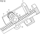
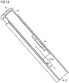
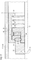
- FIGs 11 to 15 schematically show a third embodiment of a drive mechanism which according to the invention, which is suitable for being provided in the medication delivery device 1 as described in conjunction with Figure 1 .
- the drive mechanism essentially corresponds to the one described in connection with the previous embodiments.
- the drive member 20 and, in particular, the rotation member 21 are rotatable around a rotation axis which runs obliquely with respect to the axis along which the piston rod 12 is displaced (displacement axis).
- the rotation axis (cf. axis A in Figure 14 ) may run transversally, in particular perpendicularly, with respect to the displacement axis and, in particular, with respect to a main direction of extent of the piston rod 12.
- Drive member 20 and rotation member 21 may be retained by an axis member 50, which may extend through rotation member 21 and drive member 20.
- Axis A may run along axis member 50.
- Axis member may secure drive member and rotation member against displacement with respect to the housing.
- Stop member 26 may be integrated into housing 13. Of course, stop member 26 may also be embodied as a separate element.
- Axis member 50 may extend through stop member 26.
- Drive member 20 comprises an outer toothing 51. Teeth of the outer toothing 51 may extend radially away from rotation axis A. Drive member may be a toothed gear sleeve.
- the piston rod 12 is expediently provided with an outer toothing 52.
- the outer toothing 52 of piston rod 12 and the outer toothing 51 of the drive member 20 are arranged to engage one another.
- the outer toothing 52 of piston rod 12 and the outer toothing 51 of the drive member 20 may be permanently engaged.
- the piston rod 12 may be supported against deviation in the radial direction with respect to the displacement axis, for example by means of housing part 17 through an opening 53 in which the piston rod may extend.
- the dose member 34 and the rotation member 21 are not threadedly engaged. Rather, rotation member 21 and dose member 34 are connected/coupled to one another via a lever mechanism.
- the lever mechanism is adapted to convert movement of the dose member 34 with respect to the housing in the proximal direction into rotational movement of the rotation member in the first direction with respect to the housing and movement of the dose member 34 with respect to the housing in the distal direction into rotational movement of the rotation member in the second direction with respect to the housing.
- Drive member 20 is prevented to rotate during setting of the dose on account of the stop member 26 preventing rotational movement of the drive member in the first direction.
- the lever mechanism may comprise a lever 55.
- Lever 55 is preferably secured against rotational movement with respect to rotation member 21 and preferably against (simultaneous) translational movement with respect to rotation member 21.
- lever 55 is formed unitary with rotation member 21.
- Lever 55 is pivotally around the rotation axis in the first direction during dose setting and in the second direction during dose delivery.
- Dose member 34 may, preferably at its distal end, comprise an engagement member 54, e.g. a pin, for engagement with the lever 55.
- Engagement member 54 may engage the lever 55, in particular an opening 56, preferably an elongate opening 56 within lever 55.
- Stop member 26 prevents rotational movement of the drive member in the first direction during dose setting as described previously.
- Figure 16 shows a schematic sectional view of a part of a resettable drive mechanism according to an embodiment in a delivery state.
- Figure 17 shows the resettable drive mechanism of Figure 16 in a reset state.
- the drive mechanism may correspond to the one described in conjunction with Figures 2 to 9 .
- a reset mechanism for a drive mechanism as it is described in more detail below may also be provided for in the remaining drive mechanisms as described above.
- the drive mechanism described in conjunction with Figures 15 and 16 is a resettable drive mechanism.
- the drive mechanism comprises a reset mechanism.
- the reset mechanism may be switched between a reset position and a delivery position.
- Resilient member 31 exerts a force acting in axial direction on stop member 26, said force tending to keep the stop member and the drive member engaged.
- Resilient member 31 may be arranged to keep stop member in engagement and, in particular, in abutment with drive member 20 in the delivery state.
- the (biased) resilient member 31 may be supported by and, preferably, bear against bearing member 57.
- Bearing member may be support 48 of Figure 6 , for example.
- Bearing member 57 is expediently secured against rotational movement and displacement with respect to housing 13.
- Rotation of the drive member 20 in the second direction may cause the piston rod 12 to be displaced in the distal direction with respect to housing 13.
- the piston rod 13 may rotate and translate in the distal direction with respect to the housing for dose delivery as described in conjunction with Figures 2 to 10 .
- the piston rod may be moved in the distal direction with pure translatory movement (not explicitly shown, cf. a drive mechanism according to Figures 11 to 15 ).
- the drive member 20 may engage the piston rod 12.
- the drive member 20 may be splined to the piston rod 12.
- the drive member 20 preferably cannot be rotated in the first direction on account of the (permanent) interlocking of the drive member 20 and the stop member 26 when the reset mechanism is in the delivery state.
- the piston rod has to be moved in the proximal direction back into a proximal starting position in order to allow the drive mechanism to be reused.
- the drive mechanism is configured to be switchable from the delivery state to a reset state. In the reset state, the piston rod 12 may be moved in the proximal direction with respect to the housing, for example by a user screwing and/or pushing the piston rod 12 in the proximal direction.
- the drive mechanism comprises a clutch member 58.
- Clutch member 58 is movable with respect to housing 13, preferably displaceable with respect to the housing, between a delivery position D and a reset position R.
- the clutch member 58 may be moved back and forth between the delivery position and the reset position.
- the reset position may be arranged in the distal direction as seen from the delivery position.
- the clutch member 58 may be a sleeve.
- Piston rod 12 may extend through clutch member.
- drive member 20 and stop member 26 are engaged.
- drive member 20 and stop member 26 are disengaged (cf. the encircled region 59 in Figure 17 ).
- the clutch member 58 is in the reset position, the drive member may be rotated in the first direction with respect to the housing 13 without the stop member 26 preventing the rotation. Consequently, the piston rod 12 may be moved in the proximal direction, e.g. by rotation with respect to the housing and on account of a threaded engagement to the housing, due to the drive member 20 and the stop member 26 being disengaged.
- the clutch member 58 may comprise a protrusion 61.
- Protrusion 61 may protrude radially and preferably inwardly from a base portion 66 of the clutch member 58. The base portion may extend in the axial direction.
- Protrusion 61 may be arranged to move the drive member 20 and the stop member 26 out of engagement when the clutch member is moved towards reset position R.
- Protrusion 61 may be provided at or near the proximal end of the clutch member 58.
- a distal end face of protrusion 61 of clutch member 58 may be arranged to couple to and preferably to abut a proximal face of stop member 26.
- the reset mechanism furthermore comprises a clutch resilient member 60, for example a clutch spring member, like a coil spring and/or a compression spring, for example.
- a clutch resilient member 60 for example a clutch spring member, like a coil spring and/or a compression spring, for example.
- the clutch member 58 may extend along drive member 20, stop member 26, resilient member 31, bearing member 57 and/or clutch resilient member 60.
- the clutch member 58 may be rigid.
- the clutch member 58 may have a constant length.
- Clutch resilient member 60 may be biased when the clutch member 58 is in the delivery position. Biased clutch resilient member may exert a force on the clutch member that tends to move the clutch member in the reset position. Clutch resilient member 60 may bear on bearing member 57, in particular on a distal face thereof.
- Clutch member 58 may comprise a (additional) protrusion 62.
- Protrusion 62 may protrude radially and preferably inwardly from the base portion 66 of the clutch member 58.
- Protrusion 62 may be arranged in the region of the distal end of the clutch member 58.
- Protrusion 62 may be arranged to be abuttable by and is preferably abutted by clutch resilient member 60.
- Clutch resilient member 60 may be supported by and, in particular, bear on a proximal face of protrusion 62.
- the clutch resilient member 60 is arranged to exert a force on the clutch member 58 which force tends to move the clutch member 58 in the reset position R.
- this force is counteracted by a clutch stop member 63. Accordingly, in the delivery state, clutch member 58 may be held in the delivery position by the clutch stop member 63.
- clutch stop member 63 is preferably secured against displacement with respect to the housing 13.
- Clutch stop member 63 may be arranged to abut clutch member 58.
- a proximal end face of the clutch stop member 63 may abut a distal end face of the clutch member 58 in the delivery state.
- the clutch stop member 63 may be moved, for example removed, so as to allow the clutch member to move into the reset position. Thereupon, biased clutch resilient member 60 which exerts the force, which is no longer compensated by clutch stop member, on clutch member 58. The force automatically tends to move clutch member 58 in the reset position R.
- the clutch member 58 may abut stop member 26. Stop member 26 may tend to follow movement of the clutch member towards the reset position R.
- the force moving the clutch member 58 towards the reset position 58 has to be greater than the force exerted by the resilient member 31.
- the force for moving and, in particular, holding the clutch member 58 in reset position R may be provided for by clutch resilient member 60.
- the resilient member 31 and the clutch resilient member 60 may be embodied as a spring member, respectively.
- Clutch resilient member 60 in this case, preferably has a spring strength greater than the one of resilient member 31 in order to overcome the force exerted by resilient member 31.
- the clutch stop member 63 is expediently formed in the cartridge unit, for example, by the cartridge 4 or the cartridge retaining member 11. Thus, if the cartridge unit is detached from the housing 13 for replacing an empty cartridge, the clutch member 58 is moved, preferably automatically, towards and into the reset position and preferably held in the reset position.
- the distance by which the clutch member 58 moves with respect to the housing 13 when moving from delivery position into reset position is preferably chosen to be great enough to disengage toothings 27 and 28.
- the clutch member 58 is expediently secured to the drive mechanism in order to avoid the clutch member falling out of the housing.
- the clutch member may abut a proximal face of the stop member 26.
- the clutch member 58 may be axially guided with respect to the housing 13 when it is moved from the delivery position D into the reset position R and preferably also when it is moved from the delivery position back into the reset position after the reset has been completed.
- the clutch member 58 may be secured against rotational movement with respect to the housing 13.
- the medication delivery device may be reused.
- the reset mechanism may automatically and, in particular (purely) mechanically, decouple stop member 26 and drive member 20, when the cartridge unit 2 is detached from the drive unit 3 (cf. Figure 1 ).
- the only action required by a user is to move, e.g. screw and/or push, the piston rod 12 back into the starting position before a new cartridge unit 2 may be attached to the drive unit 3.
- the drive mechanism is thus easily reusable.
- the reset mechanism described herein above may be implemented easily and requires only a small amount of additional parts such as compared to the corresponding non-resettable drive mechanism.
- additional parts such as compared to the first embodiment, only two additional parts - clutch member and clutch resilient member - are required for the automatic reset mechanism.
- the reset mechanism may be an automatic one, no external action is required for disengaging stop member and drive member.
- the clutch member may be retained in the housing and, in particular, inaccessible from the outside.
- the reset mechanism may be implemented as a manual, non-automatic mechanism. It is expedient, in this case, to configure the movement of the clutch member to be externally actuable.
- the clutch member 58 may be (partly) arranged outside of the housing.
- the housing may be provided with one or more openings through which the clutch member may extend from the outside to the inside of the housing. This is particularly expedient for a non-automatic reset mechanism.
- Figure 18 shows a schematic sectional view of a part of an exemplary embodiment of a medication delivery device.
- the medication delivery device essentially corresponds to devices described further above.
- the medication delivery device 1 provides for an end-stop mechanism.
- the end-stop mechanism is configured to prevent a delivery movement of the piston rod 12 corresponding to a dose of the medication 5 which would exceed the quantity of medication 5 still present in the cartridge 4.
- the piston rod 12 comprises at least one blocking member 67.
- the piston rod 12 may comprise two or more blocking members 67.
- the blocking members 67 may be disposed oppositely.
- the respective blocking member 67 may protrude radially from the piston rod 12.
- the blocking member 67 may be arranged in the proximal end section of the piston rod 12.
- the blocking member 67 and the piston rod 12 are unitarily formed.
- the blocking member 67 may be connected to the piston rod 12. In this case, the blocking member 67 is secured against axial and rotational movement with respect to the piston rod 12.
- the blocking member 67 may protrude radially outwardly from the proximal end section of the piston rod 12.
- the blocking member 67 may be an outwardly directed flange.
- the rotation member 21 comprises a stop feature 68.
- the stop feature 68 is arranged inside the rotation member 21.
- the stop feature 68 is arranged at the distal end section of the rotation member 21.
- the stop feature 68 and the rotation member 21 are formed unitarily.
- the stop feature 68 may comprise an inwardly directed shoulder or flange portion.
- the stop feature 68 is an inwardly directed flange.
- the stop feature 68 may be configured to mechanically interact, in particular to abut, the blocking member 67 when a last dose of the medication 5 held in the cartridge 4 was dispensed, i.e. the piston 10 may have reached a most distal end position in the cartridge 4.
- blocking member 67 and stop feature 68 may be arranged to overlap.
- the blocking member 67 is displaced towards the stop feature 68 when the piston rod 12 is moved distally for delivering a dose.
- the blocking member 67 and the stop feature 68 may abut. Thereby, further distal movement of the piston rod 12 may be prevented, when the last dose was delivered.
- the device 1 effectively prevents delivery of a dose of the medication 5 which exceeds the present quantity of the medication 5 held in the cartridge 4.
- underdosing which may have fatal or even lethal consequences for the user, may be prevented. Consequently, the medication delivery device 1 described herein provides an increased safety for the user.
- the piston 10 When the stop feature 68 and the blocking member 67 mechanically cooperate, the piston 10 has expediently reached its most distal end position in the cartridge 4. Thereafter, the medication delivery device 1 may be reset as described above, for example.
- the drive mechanisms are particularly suitable for dispensing doses of the medication from and including 1 IU up to and including 30 IU, preferably from and including 3 IU up to and including 20 IU. Also, doses of 30 IU or more or 1 IU or less may be dispensed by means of the described drive mechanisms. However, doses of from and including 1 IU up to and including 30 IU are particularly suitable.
- the thread of the piston rod should have a low pitch and/or the number of teeth of the respective toothing of drive member and rotation member should be increased.
- the production costs may increase on account of the finer segmentation of the toothings and the lower pitch thread.
- the thread in the piston rod should have a higher pitch. Consequently, small deviations from a predetermined course of the thread result in major absolute deviations from the desired dose.
- the risk of a reduction in dose accuracy may be increased.
- the risk of self-locking of a threaded engagement may be increased.
- a diameter of the (outer) housing of the medication delivery device may be less than or equal to 20 mm, preferably less than or equal to 16 mm, particularly preferably less than or equal to 14 mm.
Claims (11)
- Mécanisme d'entraînement pour un dispositif d'administration de médicament (1), comprenant :- un logement (13, 17, 40) comportant une extrémité proximale et une extrémité distale,- un organe de rotation (21) qui est conçu pour être mis en rotation dans une première direction par rapport au logement (13, 17, 40) lors de la définition d'une dose d'un médicament (5) et pour être mis en rotation dans une seconde direction par rapport au logement (13, 17, 40) lors de l'administration de la dose, la seconde direction étant opposée à la première direction,- une tige de piston (12) qui est conçue pour être déplacée dans une direction distale par rapport au logement (13, 17, 40) à des fins d'administration de la dose,- un organe d'entraînement (20) qui suit le mouvement de rotation de l'organe de rotation (21) dans la seconde direction lors de l'administration de la dose, et- un organe d'arrêt (26) qui empêche un mouvement de rotation de l'organe d'entraînement (20) par rapport au logement (13, 17, 40) dans la première direction lors de la définition de la dose,- le mouvement de rotation de l'organe d'entraînement (20) dans la seconde direction étant converti en mouvement de la tige de piston (12) dans la direction distale par rapport au logement (13, 17, 40),- l'organe d'entraînement (20) et l'organe de rotation (21) étant aptes à tourner autour d'un axe de rotation commun (A), et- la tige de piston (12) étant déplacée dans la direction distale par rapport au logement (13, 17, 40) transversalement par rapport à l'axe de rotation (A),caractérisé en ce que
l'organe d'entraînement (20) est disposé entre l'organe d'arrêt (26) et l'organe de rotation (21) . - Mécanisme d'entraînement selon la revendication 1, le mécanisme d'entraînement comprenant un organe de dosage (16, 34, 41) qui peut être déplacé par rapport au logement (13, 17, 40) lors de la définition et de l'administration de la dose, et dans lequel le mouvement de l'organe de dosage par rapport au logement (13, 17, 40) est converti en mouvement de rotation de l'organe de rotation (21) par rapport au logement (13, 17, 40).
- Mécanisme d'entraînement selon la revendication 2, dans lequel l'organe de dosage (16, 34, 41) est assujetti de sorte qu'il ne puisse effectuer de mouvement de rotation par rapport au logement (13, 17, 40).
- Mécanisme d'entraînement selon la revendication 2 ou une quelconque revendication dépendant de celle-ci, dans lequel l'organe de dosage (16, 34, 41) et l'organe de rotation (21) sont reliés l'un à l'autre par un levier (55), le levier (55) étant apte à pivoter autour de l'axe de rotation (A) lors du mouvement de l'organe de dosage à des fins de définition et d'administration de la dose.
- Mécanisme d'entraînement selon l'une quelconque des revendications précédentes, dans lequel l'organe d'entraînement (20) et l'organe de rotation (21) sont reliés l'un à l'autre par un premier mécanisme d'embrayage à friction unidirectionnel, qui est configuré pour permettre un mouvement de rotation relatif entre l'organe de rotation (21) et l'organe d'entraînement (20) lors de la rotation de l'organe de rotation (21) dans la première direction à des fins de définition de la dose et pour empêcher un mouvement de rotation relatif de l'organe de rotation (21) et de l'organe d'entraînement (20) lors de la rotation de l'organe de rotation (21) dans la seconde direction à des fins d'administration de la dose.
- Mécanisme d'entraînement selon l'une quelconque des revendications précédentes, dans lequel l'organe d'entraînement (20) et l'organe d'arrêt (26) sont reliés l'un à l'autre par un second mécanisme d'embrayage à friction unidirectionnel, qui est configuré pour empêcher un mouvement de rotation relatif entre l'organe d'arrêt (26) et l'organe d'entraînement (20) lors de la rotation de l'organe de rotation (21) dans la première direction à des fins de définition de la dose et pour permettre un mouvement de rotation relatif de l'organe d'arrêt (26) et de l'organe d'entraînement (20) lors de la rotation de l'organe de rotation (21) dans la seconde direction à des fins d'administration de la dose.
- Mécanisme d'entraînement selon l'une quelconque des revendications précédentes, dans lequel l'organe d'arrêt (26) est assujetti de sorte qu'il ne puisse effectuer de mouvement de rotation par rapport au logement (13, 17, 40).
- Mécanisme d'entraînement selon l'une quelconque des revendications précédentes, dans lequel- l'organe d'entraînement (20) comprend une denture comportant une pluralité de dents et l'organe de rotation (21) comprend une denture comportant une pluralité de dents, la denture de l'organe d'entraînement (20) s'engrenant avec la denture de l'organe de rotation (21) et les dents de la denture de l'organe de rotation (21) et les dents de la denture de l'organe d'entraînement (20) s'étendant le long de l'axe de rotation (A),- l'organe d'entraînement (20) est accolé à l'organe d'arrêt (26) et à l'organe de rotation (21) lors du mouvement de l'organe de rotation (21) à des fins de définition et d'administration de la dose, et- l'organe de rotation (21) et l'organe d'arrêt (26) sont maintenus en accolement avec l'organe d'entraînement (20) par une force appliquée par un organe formant ressort (31) lors de la définition et de l'administration de la dose.
- Mécanisme d'entraînement selon la revendication 8, dans lequel l'organe d'arrêt (26) comporte une denture et l'organe d'entraînement (20) comporte une denture supplémentaire, la denture de l'organe d'entraînement (20) et la denture supplémentaire de l'organe d'entraînement (20) étant disposées de manière opposée.
- Mécanisme d'entraînement selon la revendication 8 ou 9, dans lequel les dents de la denture respective sont en forme de plan incliné.
- Dispositif d'administration de médicament (1) comprenant le mécanisme d'entraînement selon l'une quelconque des revendications précédentes et une cartouche (4), la cartouche (4) contenant une pluralité de doses du médicament (5).
Applications Claiming Priority (6)
| Application Number | Priority Date | Filing Date | Title |
|---|---|---|---|
| US12/333,459 US8840591B2 (en) | 2008-12-12 | 2008-12-12 | Drive mechanism for a medication delivery device and medication delivery device |
| US12/333,462 US8366680B2 (en) | 2008-12-12 | 2008-12-12 | Resettable drive mechanism for a medication delivery device and medication delivery device |
| EP08021629A EP2196233A1 (fr) | 2008-12-12 | 2008-12-12 | Mécanisme de commande réenclenchable pour dispositif d'administration de médicaments et dispositif d'administration de médicaments |
| EP08021628A EP2196232A1 (fr) | 2008-12-12 | 2008-12-12 | Mécanisme de commande pour dispositif d'administration de médicaments et dispositif d'administration de médicaments |
| EP09764865.3A EP2376148B1 (fr) | 2008-12-12 | 2009-12-09 | Mécanisme de commande pour dispositif d'administration de médicaments et dispositif d'administration de médicaments |
| PCT/EP2009/066742 WO2010066796A1 (fr) | 2008-12-12 | 2009-12-09 | Mécanisme d'entraînement pour dispositif d'administration de médicament et dispositif d'administration de médicament |
Related Parent Applications (2)
| Application Number | Title | Priority Date | Filing Date |
|---|---|---|---|
| EP09764865.3A Division EP2376148B1 (fr) | 2008-12-12 | 2009-12-09 | Mécanisme de commande pour dispositif d'administration de médicaments et dispositif d'administration de médicaments |
| EP09764865.3A Division-Into EP2376148B1 (fr) | 2008-12-12 | 2009-12-09 | Mécanisme de commande pour dispositif d'administration de médicaments et dispositif d'administration de médicaments |
Publications (2)
| Publication Number | Publication Date |
|---|---|
| EP3335749A1 EP3335749A1 (fr) | 2018-06-20 |
| EP3335749B1 true EP3335749B1 (fr) | 2019-10-09 |
Family
ID=44318334
Family Applications (3)
| Application Number | Title | Priority Date | Filing Date |
|---|---|---|---|
| EP08021628A Ceased EP2196232A1 (fr) | 2008-12-12 | 2008-12-12 | Mécanisme de commande pour dispositif d'administration de médicaments et dispositif d'administration de médicaments |
| EP18152599.9A Active EP3335749B1 (fr) | 2008-12-12 | 2009-12-09 | Mécanisme de commande pour dispositif d'administration de médicaments et dispositif d'administration de médicaments |
| EP15153930.1A Active EP2926850B1 (fr) | 2008-12-12 | 2009-12-09 | Mécanisme de commande pour dispositif d'administration de médicaments et dispositif d'administration de médicaments |
Family Applications Before (1)
| Application Number | Title | Priority Date | Filing Date |
|---|---|---|---|
| EP08021628A Ceased EP2196232A1 (fr) | 2008-12-12 | 2008-12-12 | Mécanisme de commande pour dispositif d'administration de médicaments et dispositif d'administration de médicaments |
Family Applications After (1)
| Application Number | Title | Priority Date | Filing Date |
|---|---|---|---|
| EP15153930.1A Active EP2926850B1 (fr) | 2008-12-12 | 2009-12-09 | Mécanisme de commande pour dispositif d'administration de médicaments et dispositif d'administration de médicaments |
Country Status (18)
| Country | Link |
|---|---|
| US (3) | US8840591B2 (fr) |
| EP (3) | EP2196232A1 (fr) |
| JP (1) | JP5599406B2 (fr) |
| KR (1) | KR20110099030A (fr) |
| CN (1) | CN102281910B (fr) |
| AU (1) | AU2009324405B2 (fr) |
| CA (1) | CA2746014A1 (fr) |
| DE (1) | DE202009019077U1 (fr) |
| DK (3) | DK3335749T3 (fr) |
| IL (1) | IL213383A (fr) |
| MX (1) | MX2011005879A (fr) |
| MY (1) | MY155197A (fr) |
| NZ (1) | NZ593301A (fr) |
| RU (1) | RU2515867C2 (fr) |
| SG (1) | SG172112A1 (fr) |
| TR (2) | TR201810016T4 (fr) |
| TW (1) | TW201026349A (fr) |
| ZA (1) | ZA201103707B (fr) |
Families Citing this family (36)
| Publication number | Priority date | Publication date | Assignee | Title |
|---|---|---|---|---|
| US8366680B2 (en) * | 2008-12-12 | 2013-02-05 | Sanofi-Aventis Deutschland Gmbh | Resettable drive mechanism for a medication delivery device and medication delivery device |
| US8840591B2 (en) | 2008-12-12 | 2014-09-23 | Sanofi-Aventis Deutschland Gmbh | Drive mechanism for a medication delivery device and medication delivery device |
| TWI530306B (zh) | 2009-06-02 | 2016-04-21 | 賽諾菲阿凡提斯德意志有限公司 | 藥物傳送裝置總成及藥物傳送裝置 |
| CN102665801B (zh) * | 2009-10-08 | 2015-06-17 | Shl集团有限责任公司 | 药物输送装置 |
| GB0918145D0 (en) | 2009-10-16 | 2009-12-02 | Owen Mumford Ltd | Injector apparatus |
| EP2501421B1 (fr) | 2009-11-20 | 2019-08-21 | Becton Dickinson and Company | Dispositif d'injection sans organe de transmission |
| EP2351591A1 (fr) * | 2010-02-02 | 2011-08-03 | Sanofi-Aventis Deutschland GmbH | Assemblage pour dispositif d'administration de médicaments et dispositif d'administration de médicaments |
| JP5807021B2 (ja) | 2010-02-18 | 2015-11-10 | サノフィ−アベンティス・ドイチュラント・ゲゼルシャフト・ミット・ベシュレンクテル・ハフツング | 自動注射器 |
| EP2399635A1 (fr) | 2010-06-28 | 2011-12-28 | Sanofi-Aventis Deutschland GmbH | Auto-injecteur |
| EP2452711A1 (fr) * | 2010-11-12 | 2012-05-16 | Sanofi-Aventis Deutschland GmbH | Mécanisme de commande pour dispositif d'administration de médicaments et dispositif d'administration de médicaments |
| EP2468330A1 (fr) | 2010-12-21 | 2012-06-27 | Sanofi-Aventis Deutschland GmbH | Auto-injecteur |
| EP2468333A1 (fr) | 2010-12-21 | 2012-06-27 | Sanofi-Aventis Deutschland GmbH | Auto-injecteur |
| USRE48593E1 (en) | 2010-12-21 | 2021-06-15 | Sanofi-Aventis Deutschland Gmbh | Auto-injector |
| SG10201700601VA (en) | 2011-03-16 | 2017-03-30 | Becton Dickinson Co | Multiple use disposable injection pen |
| US11577029B2 (en) | 2012-03-15 | 2023-02-14 | Becton, Dickinson And Company | Multiple use disposable injection pen |
| US10046118B2 (en) * | 2012-05-30 | 2018-08-14 | Sanofi-Aventis Deutschland Gmbh | Bearing for a piston rod body for a drug delivery device, a piston rod arrangement and a piston rod body |
| EP2854908B1 (fr) * | 2012-05-30 | 2018-03-21 | Sanofi-Aventis Deutschland GmbH | Mécanisme de commande pour dispositif d'administration de médicaments et dispositif d'administration de médicaments |
| EP2854907B1 (fr) | 2012-05-30 | 2019-01-16 | Sanofi-Aventis Deutschland GmbH | Mécanisme de commande pour dispositif d'administration de médicaments et dispositif d'administration de médicaments |
| EP2722065A1 (fr) * | 2012-10-18 | 2014-04-23 | Sanofi-Aventis Deutschland GmbH | Auto-injecteur |
| JP6400078B2 (ja) * | 2013-04-10 | 2018-10-03 | サノフイSanofi | 洗練された駆動機構を含む自動薬物注射デバイス |
| JP6465861B2 (ja) * | 2013-04-10 | 2019-02-06 | サノフイSanofi | ハンドヘルド薬物注射デバイスおよびそのための用量設定リミッタ機構 |
| EP2983763B1 (fr) * | 2013-04-10 | 2017-05-24 | Sanofi | Mécanisme dýentraînement pour dispositif d'administration de médicaments |
| WO2014187814A1 (fr) * | 2013-05-21 | 2014-11-27 | Novo Nordisk A/S | Dispositif de libération de médicament à chargement par l'avant avec couplage actionné de porte-cartouche et de tige de piston |
| EP2999504A1 (fr) | 2013-05-21 | 2016-03-30 | Novo Nordisk A/S | Dispositif d'administration de medicament ayant un couplage de tige de piston |
| US9956349B2 (en) * | 2013-05-21 | 2018-05-01 | Novo Nordisk A/S | Frontloaded drug delivery device with dynamic axial stop feature |
| EP2823841A1 (fr) | 2013-07-09 | 2015-01-14 | Sanofi-Aventis Deutschland GmbH | Auto-injecteur |
| CN105658265B (zh) * | 2013-08-28 | 2019-06-14 | 赛诺菲-安万特德国有限公司 | 用于药物输送装置的组件 |
| EP2923714A1 (fr) | 2014-03-28 | 2015-09-30 | Sanofi-Aventis Deutschland GmbH | Auto-injecteur declenché par contact avec la peau |
| EP3160549B1 (fr) * | 2014-06-27 | 2021-03-24 | Sanofi-Aventis Deutschland GmbH | Dispositif d'administration de médicaments |
| CN107106781B (zh) * | 2014-10-09 | 2020-09-25 | 赛诺菲 | 具有扭转弹簧以及可旋转剂量设定和校正机构的自动药物注射装置 |
| US9565945B2 (en) * | 2015-05-15 | 2017-02-14 | Knoll, Inc. | Seating device having a height adjustment mechanism |
| CH711240A2 (de) * | 2015-06-23 | 2016-12-30 | Tecpharma Licensing Ag | Autoinjektionsvorrichtung. |
| LT3730173T (lt) * | 2016-03-21 | 2023-12-27 | Eli Lilly And Company | Medicininis pristatymo prietaisas su ašies kryptimi išsiplečiančiu pavaros elementu |
| EP3437676B1 (fr) * | 2016-03-30 | 2021-08-11 | Terumo Kabushiki Kaisha | Dispositif d'administration de médicament liquide |
| SE544353C2 (sv) * | 2017-03-03 | 2022-04-19 | Asept Int Ab | Frammatningsanordning samt metod för manuell utmatning medelst och återställning av frammatningsanordning |
| US11204082B2 (en) | 2020-01-17 | 2021-12-21 | Steering Solutions Ip Holding Corporation | Steer by wire rotational travel stop |
Family Cites Families (49)
| Publication number | Priority date | Publication date | Assignee | Title |
|---|---|---|---|---|
| US533575A (en) | 1895-02-05 | wilkens | ||
| US1718596A (en) * | 1927-08-08 | 1929-06-25 | Arthur E Smith | Automatic syringe |
| US2653604A (en) * | 1950-12-19 | 1953-09-29 | Jr George N Hein | Injection device |
| US4465478A (en) * | 1982-10-14 | 1984-08-14 | Collagen Corporation | Syringe force amplification device |
| US4592745A (en) | 1984-02-29 | 1986-06-03 | Novo Industri A/S | Dispenser |
| US5226895A (en) | 1989-06-05 | 1993-07-13 | Eli Lilly And Company | Multiple dose injection pen |
| GB9007113D0 (en) | 1990-03-29 | 1990-05-30 | Sams Bernard | Dispensing device |
| ES2074771T3 (es) | 1991-07-24 | 1995-09-16 | Medico Dev Investment Co | Inyector. |
| DK175491D0 (da) * | 1991-10-18 | 1991-10-18 | Novo Nordisk As | Apparat |
| US5279586A (en) | 1992-02-04 | 1994-01-18 | Becton, Dickinson And Company | Reusable medication delivery pen |
| US5320609A (en) | 1992-12-07 | 1994-06-14 | Habley Medical Technology Corporation | Automatic pharmaceutical dispensing syringe |
| GB9226423D0 (en) * | 1992-12-18 | 1993-02-10 | Sams Bernard | Incrementing mechanisms |
| US5383865A (en) | 1993-03-15 | 1995-01-24 | Eli Lilly And Company | Medication dispensing device |
| ZA941881B (en) | 1993-04-02 | 1995-09-18 | Lilly Co Eli | Manifold medication injection apparatus and method |
| US5725508A (en) * | 1994-06-22 | 1998-03-10 | Becton Dickinson And Company | Quick connect medication delivery pen |
| US5827232A (en) * | 1994-06-22 | 1998-10-27 | Becton Dickinson And Company | Quick connect medication delivery pen |
| US5582598A (en) * | 1994-09-19 | 1996-12-10 | Becton Dickinson And Company | Medication delivery pen with variable increment dose scale |
| CA2213682C (fr) | 1995-03-07 | 2009-10-06 | Eli Lilly And Company | Distributeur recyclable de medicament |
| US5688251A (en) | 1995-09-19 | 1997-11-18 | Becton Dickinson And Company | Cartridge loading and priming mechanism for a pen injector |
| US5674204A (en) | 1995-09-19 | 1997-10-07 | Becton Dickinson And Company | Medication delivery pen cap actuated dose delivery clutch |
| DE19730999C1 (de) | 1997-07-18 | 1998-12-10 | Disetronic Licensing Ag | Dosierknopfsicherung an einer Vorrichtung zur dosierten Verabreichung eines injizierbaren Produkts |
| US5957896A (en) | 1997-08-11 | 1999-09-28 | Becton, Dickinson And Company | Medication delivery pen |
| EP1003581B1 (fr) * | 1998-01-30 | 2000-11-08 | Novo Nordisk A/S | Seringue d'injection |
| US5961495A (en) | 1998-02-20 | 1999-10-05 | Becton, Dickinson And Company | Medication delivery pen having a priming mechanism |
| US6221053B1 (en) | 1998-02-20 | 2001-04-24 | Becton, Dickinson And Company | Multi-featured medication delivery pen |
| US6248095B1 (en) | 1998-02-23 | 2001-06-19 | Becton, Dickinson And Company | Low-cost medication delivery pen |
| AU6892100A (en) | 1999-08-05 | 2001-03-05 | Becton Dickinson & Company | Medication delivery pen |
| TW453884B (en) | 1999-09-16 | 2001-09-11 | Novo Nordisk As | Dose setting limiter |
| GB0007071D0 (en) | 2000-03-24 | 2000-05-17 | Sams Bernard | One-way clutch mechanisms and injector devices |
| US6663602B2 (en) * | 2000-06-16 | 2003-12-16 | Novo Nordisk A/S | Injection device |
| IL156245A0 (en) | 2000-12-22 | 2004-01-04 | Dca Design Int Ltd | Drive mechanism for an injection device |
| US6899699B2 (en) | 2001-01-05 | 2005-05-31 | Novo Nordisk A/S | Automatic injection device with reset feature |
| EP2258425B1 (fr) | 2001-05-16 | 2013-01-30 | Eli Lilly and Company | Appareil injecteur de médication |
| EP1487520A1 (fr) * | 2002-03-18 | 2004-12-22 | Eli Lilly And Company | Appareil de distribution de medicament dote d'un train d'engrenages apportant un avantage technique |
| JP2005532129A (ja) * | 2002-07-10 | 2005-10-27 | ノボ・ノルデイスク・エー/エス | 投与量設定リミッタを備える注入器 |
| EP1542744B1 (fr) * | 2002-09-24 | 2009-06-24 | SHL Group AB | Dispositif d'injection |
| GB0304823D0 (en) | 2003-03-03 | 2003-04-09 | Dca Internat Ltd | Improvements in and relating to a pen-type injector |
| GB0304822D0 (en) | 2003-03-03 | 2003-04-09 | Dca Internat Ltd | Improvements in and relating to a pen-type injector |
| DE102004063644A1 (de) * | 2004-12-31 | 2006-07-20 | Tecpharma Licensing Ag | Vorrichtung zur dosierten Verabreichung eines fluiden Produkts mit Drehfederantrieb |
| CA2595069C (fr) * | 2005-01-18 | 2011-05-03 | Wockhardt Americas Inc | Dispositifs d'injection de medicaments en forme de stylo |
| DE102005060929A1 (de) | 2005-09-14 | 2007-03-15 | Tecpharma Licensing Ag | Injektionsvorrichtung mit Zweiwege-Rutschkupplung |
| JP5253387B2 (ja) * | 2006-05-18 | 2013-07-31 | ノボ・ノルデイスク・エー/エス | モード固定手段を備えている注入装置 |
| EP1923085A1 (fr) * | 2006-11-17 | 2008-05-21 | Sanofi-Aventis Deutschland GmbH | Mechanisme de dosage et transmission pour dispositif d'administration de médicament |
| JP5213875B2 (ja) * | 2006-12-21 | 2013-06-19 | ノボ・ノルデイスク・エー/エス | 注射装置 |
| ATE486660T1 (de) * | 2007-05-14 | 2010-11-15 | Shl Group Ab | Abgabegerät |
| US8647309B2 (en) | 2008-05-02 | 2014-02-11 | Sanofi-Aventis Deutschland Gmbh | Medication delivery device |
| US8840591B2 (en) | 2008-12-12 | 2014-09-23 | Sanofi-Aventis Deutschland Gmbh | Drive mechanism for a medication delivery device and medication delivery device |
| US8366680B2 (en) | 2008-12-12 | 2013-02-05 | Sanofi-Aventis Deutschland Gmbh | Resettable drive mechanism for a medication delivery device and medication delivery device |
| US8827232B2 (en) | 2011-01-13 | 2014-09-09 | Quick-Sling, Llc | Support apparatus |
-
2008
- 2008-12-12 US US12/333,459 patent/US8840591B2/en active Active
- 2008-12-12 EP EP08021628A patent/EP2196232A1/fr not_active Ceased
-
2009
- 2009-12-09 EP EP18152599.9A patent/EP3335749B1/fr active Active
- 2009-12-09 JP JP2011540078A patent/JP5599406B2/ja active Active
- 2009-12-09 DE DE202009019077.3U patent/DE202009019077U1/de not_active Expired - Lifetime
- 2009-12-09 MY MYPI2011002316A patent/MY155197A/en unknown
- 2009-12-09 DK DK18152599.9T patent/DK3335749T3/da active
- 2009-12-09 DK DK15153930.1T patent/DK2926850T3/en active
- 2009-12-09 RU RU2011128680/14A patent/RU2515867C2/ru not_active IP Right Cessation
- 2009-12-09 CA CA2746014A patent/CA2746014A1/fr not_active Abandoned
- 2009-12-09 TR TR2018/10016T patent/TR201810016T4/tr unknown
- 2009-12-09 KR KR20117015646A patent/KR20110099030A/ko not_active Application Discontinuation
- 2009-12-09 SG SG2011042934A patent/SG172112A1/en unknown
- 2009-12-09 NZ NZ593301A patent/NZ593301A/xx not_active IP Right Cessation
- 2009-12-09 DK DK09764865.3T patent/DK2376148T3/en active
- 2009-12-09 AU AU2009324405A patent/AU2009324405B2/en not_active Ceased
- 2009-12-09 EP EP15153930.1A patent/EP2926850B1/fr active Active
- 2009-12-09 CN CN200980154662.1A patent/CN102281910B/zh not_active Withdrawn - After Issue
- 2009-12-09 TR TR2018/09841T patent/TR201809841T4/tr unknown
- 2009-12-09 MX MX2011005879A patent/MX2011005879A/es not_active Application Discontinuation
- 2009-12-10 TW TW98142169A patent/TW201026349A/zh unknown
-
2011
- 2011-05-20 ZA ZA2011/03707A patent/ZA201103707B/en unknown
- 2011-06-05 IL IL213383A patent/IL213383A/en not_active IP Right Cessation
-
2015
- 2015-03-09 US US14/641,544 patent/US9539396B2/en active Active
- 2015-09-18 US US14/858,102 patent/US9457152B2/en active Active
Non-Patent Citations (1)
| Title |
|---|
| None * |
Also Published As
Similar Documents
| Publication | Publication Date | Title |
|---|---|---|
| US11577026B2 (en) | Drive mechanism for a medication delivery device and medication delivery device | |
| EP3335749B1 (fr) | Mécanisme de commande pour dispositif d'administration de médicaments et dispositif d'administration de médicaments | |
| US9089652B2 (en) | Drive mechanism for a medication delivery device and medication delivery device | |
| US8968258B2 (en) | Resettable drive mechanism for a medication delivery device and medication delivery device | |
| US8968256B2 (en) | Resettable drive mechanism for a medication delivery device and medication delivery device |
Legal Events
| Date | Code | Title | Description |
|---|---|---|---|
| PUAI | Public reference made under article 153(3) epc to a published international application that has entered the european phase |
Free format text: ORIGINAL CODE: 0009012 |
|
| STAA | Information on the status of an ep patent application or granted ep patent |
Free format text: STATUS: THE APPLICATION HAS BEEN PUBLISHED |
|
| AC | Divisional application: reference to earlier application |
Ref document number: 2376148 Country of ref document: EP Kind code of ref document: P |
|
| AK | Designated contracting states |
Kind code of ref document: A1 Designated state(s): AT BE BG CH CY CZ DE DK EE ES FI FR GB GR HR HU IE IS IT LI LT LU LV MC MK MT NL NO PL PT RO SE SI SK SM TR |
|
| AX | Request for extension of the european patent |
Extension state: AL BA RS |
|
| STAA | Information on the status of an ep patent application or granted ep patent |
Free format text: STATUS: REQUEST FOR EXAMINATION WAS MADE |
|
| 17P | Request for examination filed |
Effective date: 20181210 |
|
| RBV | Designated contracting states (corrected) |
Designated state(s): AT BE BG CH CY CZ DE DK EE ES FI FR GB GR HR HU IE IS IT LI LT LU LV MC MK MT NL NO PL PT RO SE SI SK SM TR |
|
| RIC1 | Information provided on ipc code assigned before grant |
Ipc: A61M 5/24 20060101ALN20190308BHEP Ipc: A61M 5/315 20060101AFI20190308BHEP |
|
| GRAP | Despatch of communication of intention to grant a patent |
Free format text: ORIGINAL CODE: EPIDOSNIGR1 |
|
| STAA | Information on the status of an ep patent application or granted ep patent |
Free format text: STATUS: GRANT OF PATENT IS INTENDED |
|
| RIC1 | Information provided on ipc code assigned before grant |
Ipc: A61M 5/24 20060101ALN20190423BHEP Ipc: A61M 5/315 20060101AFI20190423BHEP |
|
| INTG | Intention to grant announced |
Effective date: 20190509 |
|
| GRAS | Grant fee paid |
Free format text: ORIGINAL CODE: EPIDOSNIGR3 |
|
| GRAA | (expected) grant |
Free format text: ORIGINAL CODE: 0009210 |
|
| STAA | Information on the status of an ep patent application or granted ep patent |
Free format text: STATUS: THE PATENT HAS BEEN GRANTED |
|
| AC | Divisional application: reference to earlier application |
Ref document number: 2376148 Country of ref document: EP Kind code of ref document: P |
|
| AK | Designated contracting states |
Kind code of ref document: B1 Designated state(s): AT BE BG CH CY CZ DE DK EE ES FI FR GB GR HR HU IE IS IT LI LT LU LV MC MK MT NL NO PL PT RO SE SI SK SM TR |
|
| REG | Reference to a national code |
Ref country code: GB Ref legal event code: FG4D |
|
| REG | Reference to a national code |
Ref country code: CH Ref legal event code: EP |
|
| REG | Reference to a national code |
Ref country code: DE Ref legal event code: R096 Ref document number: 602009060129 Country of ref document: DE |
|
| REG | Reference to a national code |
Ref country code: IE Ref legal event code: FG4D |
|
| REG | Reference to a national code |
Ref country code: AT Ref legal event code: REF Ref document number: 1188064 Country of ref document: AT Kind code of ref document: T Effective date: 20191115 |
|
| REG | Reference to a national code |
Ref country code: DK Ref legal event code: T3 Effective date: 20191218 |
|
| REG | Reference to a national code |
Ref country code: NL Ref legal event code: MP Effective date: 20191009 |
|
| REG | Reference to a national code |
Ref country code: LT Ref legal event code: MG4D |
|
| REG | Reference to a national code |
Ref country code: AT Ref legal event code: MK05 Ref document number: 1188064 Country of ref document: AT Kind code of ref document: T Effective date: 20191009 |
|
| PG25 | Lapsed in a contracting state [announced via postgrant information from national office to epo] |
Ref country code: FI Free format text: LAPSE BECAUSE OF FAILURE TO SUBMIT A TRANSLATION OF THE DESCRIPTION OR TO PAY THE FEE WITHIN THE PRESCRIBED TIME-LIMIT Effective date: 20191009 Ref country code: GR Free format text: LAPSE BECAUSE OF FAILURE TO SUBMIT A TRANSLATION OF THE DESCRIPTION OR TO PAY THE FEE WITHIN THE PRESCRIBED TIME-LIMIT Effective date: 20200110 Ref country code: BG Free format text: LAPSE BECAUSE OF FAILURE TO SUBMIT A TRANSLATION OF THE DESCRIPTION OR TO PAY THE FEE WITHIN THE PRESCRIBED TIME-LIMIT Effective date: 20200109 Ref country code: NO Free format text: LAPSE BECAUSE OF FAILURE TO SUBMIT A TRANSLATION OF THE DESCRIPTION OR TO PAY THE FEE WITHIN THE PRESCRIBED TIME-LIMIT Effective date: 20200109 Ref country code: LV Free format text: LAPSE BECAUSE OF FAILURE TO SUBMIT A TRANSLATION OF THE DESCRIPTION OR TO PAY THE FEE WITHIN THE PRESCRIBED TIME-LIMIT Effective date: 20191009 Ref country code: SE Free format text: LAPSE BECAUSE OF FAILURE TO SUBMIT A TRANSLATION OF THE DESCRIPTION OR TO PAY THE FEE WITHIN THE PRESCRIBED TIME-LIMIT Effective date: 20191009 Ref country code: NL Free format text: LAPSE BECAUSE OF FAILURE TO SUBMIT A TRANSLATION OF THE DESCRIPTION OR TO PAY THE FEE WITHIN THE PRESCRIBED TIME-LIMIT Effective date: 20191009 Ref country code: AT Free format text: LAPSE BECAUSE OF FAILURE TO SUBMIT A TRANSLATION OF THE DESCRIPTION OR TO PAY THE FEE WITHIN THE PRESCRIBED TIME-LIMIT Effective date: 20191009 Ref country code: ES Free format text: LAPSE BECAUSE OF FAILURE TO SUBMIT A TRANSLATION OF THE DESCRIPTION OR TO PAY THE FEE WITHIN THE PRESCRIBED TIME-LIMIT Effective date: 20191009 Ref country code: PL Free format text: LAPSE BECAUSE OF FAILURE TO SUBMIT A TRANSLATION OF THE DESCRIPTION OR TO PAY THE FEE WITHIN THE PRESCRIBED TIME-LIMIT Effective date: 20191009 Ref country code: LT Free format text: LAPSE BECAUSE OF FAILURE TO SUBMIT A TRANSLATION OF THE DESCRIPTION OR TO PAY THE FEE WITHIN THE PRESCRIBED TIME-LIMIT Effective date: 20191009 Ref country code: PT Free format text: LAPSE BECAUSE OF FAILURE TO SUBMIT A TRANSLATION OF THE DESCRIPTION OR TO PAY THE FEE WITHIN THE PRESCRIBED TIME-LIMIT Effective date: 20200210 |
|
| PG25 | Lapsed in a contracting state [announced via postgrant information from national office to epo] |
Ref country code: IS Free format text: LAPSE BECAUSE OF FAILURE TO SUBMIT A TRANSLATION OF THE DESCRIPTION OR TO PAY THE FEE WITHIN THE PRESCRIBED TIME-LIMIT Effective date: 20200224 Ref country code: HR Free format text: LAPSE BECAUSE OF FAILURE TO SUBMIT A TRANSLATION OF THE DESCRIPTION OR TO PAY THE FEE WITHIN THE PRESCRIBED TIME-LIMIT Effective date: 20191009 |
|
| REG | Reference to a national code |
Ref country code: DE Ref legal event code: R097 Ref document number: 602009060129 Country of ref document: DE |
|
| PG2D | Information on lapse in contracting state deleted |
Ref country code: IS |
|
| PG25 | Lapsed in a contracting state [announced via postgrant information from national office to epo] |
Ref country code: EE Free format text: LAPSE BECAUSE OF FAILURE TO SUBMIT A TRANSLATION OF THE DESCRIPTION OR TO PAY THE FEE WITHIN THE PRESCRIBED TIME-LIMIT Effective date: 20191009 Ref country code: CZ Free format text: LAPSE BECAUSE OF FAILURE TO SUBMIT A TRANSLATION OF THE DESCRIPTION OR TO PAY THE FEE WITHIN THE PRESCRIBED TIME-LIMIT Effective date: 20191009 Ref country code: RO Free format text: LAPSE BECAUSE OF FAILURE TO SUBMIT A TRANSLATION OF THE DESCRIPTION OR TO PAY THE FEE WITHIN THE PRESCRIBED TIME-LIMIT Effective date: 20191009 Ref country code: IS Free format text: LAPSE BECAUSE OF FAILURE TO SUBMIT A TRANSLATION OF THE DESCRIPTION OR TO PAY THE FEE WITHIN THE PRESCRIBED TIME-LIMIT Effective date: 20200209 |
|
| PLBE | No opposition filed within time limit |
Free format text: ORIGINAL CODE: 0009261 |
|
| STAA | Information on the status of an ep patent application or granted ep patent |
Free format text: STATUS: NO OPPOSITION FILED WITHIN TIME LIMIT |
|
| REG | Reference to a national code |
Ref country code: BE Ref legal event code: MM Effective date: 20191231 |
|
| PG25 | Lapsed in a contracting state [announced via postgrant information from national office to epo] |
Ref country code: SM Free format text: LAPSE BECAUSE OF FAILURE TO SUBMIT A TRANSLATION OF THE DESCRIPTION OR TO PAY THE FEE WITHIN THE PRESCRIBED TIME-LIMIT Effective date: 20191009 Ref country code: IT Free format text: LAPSE BECAUSE OF FAILURE TO SUBMIT A TRANSLATION OF THE DESCRIPTION OR TO PAY THE FEE WITHIN THE PRESCRIBED TIME-LIMIT Effective date: 20191009 Ref country code: SK Free format text: LAPSE BECAUSE OF FAILURE TO SUBMIT A TRANSLATION OF THE DESCRIPTION OR TO PAY THE FEE WITHIN THE PRESCRIBED TIME-LIMIT Effective date: 20191009 Ref country code: MC Free format text: LAPSE BECAUSE OF FAILURE TO SUBMIT A TRANSLATION OF THE DESCRIPTION OR TO PAY THE FEE WITHIN THE PRESCRIBED TIME-LIMIT Effective date: 20191009 |
|
| 26N | No opposition filed |
Effective date: 20200710 |
|
| PG25 | Lapsed in a contracting state [announced via postgrant information from national office to epo] |
Ref country code: IE Free format text: LAPSE BECAUSE OF NON-PAYMENT OF DUE FEES Effective date: 20191209 Ref country code: LU Free format text: LAPSE BECAUSE OF NON-PAYMENT OF DUE FEES Effective date: 20191209 |
|
| PG25 | Lapsed in a contracting state [announced via postgrant information from national office to epo] |
Ref country code: BE Free format text: LAPSE BECAUSE OF NON-PAYMENT OF DUE FEES Effective date: 20191231 Ref country code: SI Free format text: LAPSE BECAUSE OF FAILURE TO SUBMIT A TRANSLATION OF THE DESCRIPTION OR TO PAY THE FEE WITHIN THE PRESCRIBED TIME-LIMIT Effective date: 20191009 |
|
| PG25 | Lapsed in a contracting state [announced via postgrant information from national office to epo] |
Ref country code: CY Free format text: LAPSE BECAUSE OF FAILURE TO SUBMIT A TRANSLATION OF THE DESCRIPTION OR TO PAY THE FEE WITHIN THE PRESCRIBED TIME-LIMIT Effective date: 20191009 |
|
| PG25 | Lapsed in a contracting state [announced via postgrant information from national office to epo] |
Ref country code: MT Free format text: LAPSE BECAUSE OF FAILURE TO SUBMIT A TRANSLATION OF THE DESCRIPTION OR TO PAY THE FEE WITHIN THE PRESCRIBED TIME-LIMIT Effective date: 20191009 Ref country code: HU Free format text: LAPSE BECAUSE OF FAILURE TO SUBMIT A TRANSLATION OF THE DESCRIPTION OR TO PAY THE FEE WITHIN THE PRESCRIBED TIME-LIMIT; INVALID AB INITIO Effective date: 20091209 |
|
| PG25 | Lapsed in a contracting state [announced via postgrant information from national office to epo] |
Ref country code: MK Free format text: LAPSE BECAUSE OF FAILURE TO SUBMIT A TRANSLATION OF THE DESCRIPTION OR TO PAY THE FEE WITHIN THE PRESCRIBED TIME-LIMIT Effective date: 20191009 |
|
| PGFP | Annual fee paid to national office [announced via postgrant information from national office to epo] |
Ref country code: CH Payment date: 20230101 Year of fee payment: 14 |
|
| P01 | Opt-out of the competence of the unified patent court (upc) registered |
Effective date: 20230421 |
|
| PGFP | Annual fee paid to national office [announced via postgrant information from national office to epo] |
Ref country code: FR Payment date: 20230929 Year of fee payment: 15 |
|
| PGFP | Annual fee paid to national office [announced via postgrant information from national office to epo] |
Ref country code: GB Payment date: 20231019 Year of fee payment: 15 |
|
| PGFP | Annual fee paid to national office [announced via postgrant information from national office to epo] |
Ref country code: TR Payment date: 20231207 Year of fee payment: 15 Ref country code: DK Payment date: 20231214 Year of fee payment: 15 Ref country code: DE Payment date: 20231017 Year of fee payment: 15 |