EP3334561B1 - Machine for finishing a work piece, and having a highly controllable treatment tool - Google Patents
Machine for finishing a work piece, and having a highly controllable treatment tool Download PDFInfo
- Publication number
- EP3334561B1 EP3334561B1 EP16837532.7A EP16837532A EP3334561B1 EP 3334561 B1 EP3334561 B1 EP 3334561B1 EP 16837532 A EP16837532 A EP 16837532A EP 3334561 B1 EP3334561 B1 EP 3334561B1
- Authority
- EP
- European Patent Office
- Prior art keywords
- treatment tool
- machine
- tool
- work piece
- treatment
- Prior art date
- Legal status (The legal status is an assumption and is not a legal conclusion. Google has not performed a legal analysis and makes no representation as to the accuracy of the status listed.)
- Active
Links
- 238000011109 contamination Methods 0.000 claims description 10
- 238000000034 method Methods 0.000 claims description 8
- 238000012545 processing Methods 0.000 claims description 7
- HBMJWWWQQXIZIP-UHFFFAOYSA-N silicon carbide Chemical compound [Si+]#[C-] HBMJWWWQQXIZIP-UHFFFAOYSA-N 0.000 claims description 7
- 229910010271 silicon carbide Inorganic materials 0.000 claims description 6
- 230000008569 process Effects 0.000 claims description 4
- 235000012431 wafers Nutrition 0.000 description 30
- 230000033001 locomotion Effects 0.000 description 12
- 238000004140 cleaning Methods 0.000 description 10
- 238000005498 polishing Methods 0.000 description 8
- 239000004065 semiconductor Substances 0.000 description 6
- 239000000758 substrate Substances 0.000 description 6
- 239000000463 material Substances 0.000 description 5
- 238000012937 correction Methods 0.000 description 3
- 238000001459 lithography Methods 0.000 description 3
- 230000003746 surface roughness Effects 0.000 description 2
- 229910002601 GaN Inorganic materials 0.000 description 1
- 229910001218 Gallium arsenide Inorganic materials 0.000 description 1
- 238000009825 accumulation Methods 0.000 description 1
- 230000004075 alteration Effects 0.000 description 1
- 238000006243 chemical reaction Methods 0.000 description 1
- 238000005202 decontamination Methods 0.000 description 1
- 230000003588 decontaminative effect Effects 0.000 description 1
- 238000010586 diagram Methods 0.000 description 1
- 238000006073 displacement reaction Methods 0.000 description 1
- 230000000694 effects Effects 0.000 description 1
- 230000001747 exhibiting effect Effects 0.000 description 1
- 238000007519 figuring Methods 0.000 description 1
- 238000011065 in-situ storage Methods 0.000 description 1
- 238000010884 ion-beam technique Methods 0.000 description 1
- 238000004519 manufacturing process Methods 0.000 description 1
- 238000012986 modification Methods 0.000 description 1
- 230000004048 modification Effects 0.000 description 1
- 238000005457 optimization Methods 0.000 description 1
- 230000002093 peripheral effect Effects 0.000 description 1
- 238000003825 pressing Methods 0.000 description 1
- 230000004044 response Effects 0.000 description 1
- 238000007788 roughening Methods 0.000 description 1
- 229910052594 sapphire Inorganic materials 0.000 description 1
- 239000010980 sapphire Substances 0.000 description 1
- 238000012360 testing method Methods 0.000 description 1
- 238000012546 transfer Methods 0.000 description 1
- 238000013519 translation Methods 0.000 description 1
Images


Classifications
-
- B—PERFORMING OPERATIONS; TRANSPORTING
- B24—GRINDING; POLISHING
- B24B—MACHINES, DEVICES, OR PROCESSES FOR GRINDING OR POLISHING; DRESSING OR CONDITIONING OF ABRADING SURFACES; FEEDING OF GRINDING, POLISHING, OR LAPPING AGENTS
- B24B37/00—Lapping machines or devices; Accessories
- B24B37/005—Control means for lapping machines or devices
-
- B—PERFORMING OPERATIONS; TRANSPORTING
- B24—GRINDING; POLISHING
- B24B—MACHINES, DEVICES, OR PROCESSES FOR GRINDING OR POLISHING; DRESSING OR CONDITIONING OF ABRADING SURFACES; FEEDING OF GRINDING, POLISHING, OR LAPPING AGENTS
- B24B1/00—Processes of grinding or polishing; Use of auxiliary equipment in connection with such processes
-
- B—PERFORMING OPERATIONS; TRANSPORTING
- B24—GRINDING; POLISHING
- B24B—MACHINES, DEVICES, OR PROCESSES FOR GRINDING OR POLISHING; DRESSING OR CONDITIONING OF ABRADING SURFACES; FEEDING OF GRINDING, POLISHING, OR LAPPING AGENTS
- B24B27/00—Other grinding machines or devices
- B24B27/0015—Hanging grinding machines
-
- B—PERFORMING OPERATIONS; TRANSPORTING
- B24—GRINDING; POLISHING
- B24B—MACHINES, DEVICES, OR PROCESSES FOR GRINDING OR POLISHING; DRESSING OR CONDITIONING OF ABRADING SURFACES; FEEDING OF GRINDING, POLISHING, OR LAPPING AGENTS
- B24B37/00—Lapping machines or devices; Accessories
- B24B37/04—Lapping machines or devices; Accessories designed for working plane surfaces
- B24B37/07—Lapping machines or devices; Accessories designed for working plane surfaces characterised by the movement of the work or lapping tool
- B24B37/10—Lapping machines or devices; Accessories designed for working plane surfaces characterised by the movement of the work or lapping tool for single side lapping
- B24B37/105—Lapping machines or devices; Accessories designed for working plane surfaces characterised by the movement of the work or lapping tool for single side lapping the workpieces or work carriers being actively moved by a drive, e.g. in a combined rotary and translatory movement
- B24B37/107—Lapping machines or devices; Accessories designed for working plane surfaces characterised by the movement of the work or lapping tool for single side lapping the workpieces or work carriers being actively moved by a drive, e.g. in a combined rotary and translatory movement in a rotary movement only, about an axis being stationary during lapping
-
- B—PERFORMING OPERATIONS; TRANSPORTING
- B24—GRINDING; POLISHING
- B24B—MACHINES, DEVICES, OR PROCESSES FOR GRINDING OR POLISHING; DRESSING OR CONDITIONING OF ABRADING SURFACES; FEEDING OF GRINDING, POLISHING, OR LAPPING AGENTS
- B24B41/00—Component parts such as frames, beds, carriages, headstocks
- B24B41/04—Headstocks; Working-spindles; Features relating thereto
- B24B41/047—Grinding heads for working on plane surfaces
-
- B—PERFORMING OPERATIONS; TRANSPORTING
- B24—GRINDING; POLISHING
- B24B—MACHINES, DEVICES, OR PROCESSES FOR GRINDING OR POLISHING; DRESSING OR CONDITIONING OF ABRADING SURFACES; FEEDING OF GRINDING, POLISHING, OR LAPPING AGENTS
- B24B7/00—Machines or devices designed for grinding plane surfaces on work, including polishing plane glass surfaces; Accessories therefor
- B24B7/005—Portal grinding machines
-
- B—PERFORMING OPERATIONS; TRANSPORTING
- B24—GRINDING; POLISHING
- B24B—MACHINES, DEVICES, OR PROCESSES FOR GRINDING OR POLISHING; DRESSING OR CONDITIONING OF ABRADING SURFACES; FEEDING OF GRINDING, POLISHING, OR LAPPING AGENTS
- B24B7/00—Machines or devices designed for grinding plane surfaces on work, including polishing plane glass surfaces; Accessories therefor
- B24B7/04—Machines or devices designed for grinding plane surfaces on work, including polishing plane glass surfaces; Accessories therefor involving a rotary work-table
-
- B—PERFORMING OPERATIONS; TRANSPORTING
- B24—GRINDING; POLISHING
- B24B—MACHINES, DEVICES, OR PROCESSES FOR GRINDING OR POLISHING; DRESSING OR CONDITIONING OF ABRADING SURFACES; FEEDING OF GRINDING, POLISHING, OR LAPPING AGENTS
- B24B7/00—Machines or devices designed for grinding plane surfaces on work, including polishing plane glass surfaces; Accessories therefor
- B24B7/20—Machines or devices designed for grinding plane surfaces on work, including polishing plane glass surfaces; Accessories therefor characterised by a special design with respect to properties of the material of non-metallic articles to be ground
- B24B7/22—Machines or devices designed for grinding plane surfaces on work, including polishing plane glass surfaces; Accessories therefor characterised by a special design with respect to properties of the material of non-metallic articles to be ground for grinding inorganic material, e.g. stone, ceramics, porcelain
- B24B7/228—Machines or devices designed for grinding plane surfaces on work, including polishing plane glass surfaces; Accessories therefor characterised by a special design with respect to properties of the material of non-metallic articles to be ground for grinding inorganic material, e.g. stone, ceramics, porcelain for grinding thin, brittle parts, e.g. semiconductors, wafers
Definitions
- the instant disclosure pertains to machines that have a treatment tool for processing (e.g., grinding/lapping/polishing/texturing) a work piece so that a surface of the work piece has a desired elevation or profile (i.e., a "figure"), and desired texture (roughness/smoothness).
- a treatment tool for processing e.g., grinding/lapping/polishing/texturing
- the treatment tool may be part of a larger working head assembly.
- Chucks such as pin chucks, are used to hold flat components for processing.
- the most common use is to hold wafers (Si, SiC, GaAs, GaN, Sapphire, other) during processing to yield a semiconductor device.
- Other uses include holding substrates during the fabrication of flat panel displays, solar cells and other such manufactured products.
- These chucking components are known by many names, including wafer chucks, wafer tables, wafer handling devices, etc.
- a pin chuck consists of a rigid body with a plurality of pins on the surface on which the substrate to be processed (e.g., Si wafer) rests.
- the pins exist in many geometries, and go by many names including burls, mesas, bumps, proud lands, proud rings, etc.
- the surface that supports whatever is to be chucked (e.g., a semiconductor wafer) needs to be flat to a very high degree of precision.
- the flatness is measured in nanometers (nm).
- treatment tool with the surface of a work piece to be processed to physically remove material from the work piece through grinding, lapping, texturing and/or polishing.
- the machine of the instant disclosure addresses this problem, and provides a solution.
- DE 196 49 216 A1 is the basis for the preamble of claim 1 and discloses a method that involves pressing a workpiece against a rotation disk.
- the workpiece is rotated about a centre of rotation.
- the centre of rotation is offset relative to a centre of rotation of the disk.
- the workpiece or the disk undergo a revolution about a centre of revolution which is offset relative to the centres of rotation of the workpiece and the disk.
- the surface of the workpiece is treated by two rotations and one revolution.
- the apparatus for carrying out the method has a table for holding and rotating the disk. It also has a workpiece table for holding and rotating the workpiece.
- the disk may be a cup shaped grinding disk.
- US 2004/116058 A1 discloses a precision sub-aperture polishing tool that has a compliant, toroidal polishing member mountable to a support member. A circumferential portion of the polishing member extends uniformly beyond the peripheral surface of the support member and forms a clearance with the work piece surface during polishing operations.
- US 2004/092217 A1 discloses a wear ring assembly for use in a workpiece (e.g. a semiconductor wafer) polishing apparatus.
- the wear ring assembly comprises a wear element and a backing ring.
- the backing ring includes a fulcrum and is configured to transfer a component of pressure applied to the backing ring to the wear element via the fulcrum. In this manner, a substantially uniform vertical displacement of the wear ring is achieved.
- the machine is configured to control multiple independent input variables simultaneously, the controllable variables selected from the group consisting of (i) velocity, (ii) rotation, and (iii) dither of the treatment tool, and (iv) pressure of the treatment tool against the surface.
- the machine can move the treatment tool with six degrees of freedom.
- a machine having a treatment tool that grinds a surface to a desired profile imparts a desired roughness to that surface, and removes contamination in a single operation.
- the treatment tool which may be part of a larger assembly sometimes referred to as a "working head", features a flat surface configured to contact and abrade the surface of the work piece as the treatment tool passes over it.
- the treatment tool may have about the same hardness as the work piece.
- the treatment tool may have the appearance of a disc. Alternatively, it may appear as an annulus, ring or toroid. If shaped as an annulus or ring or toroid, the space inside or within the annular space may contain a second treatment tool. Further, the treatment tool may feature a plurality of rings or toroids gathered or assembled together, and collectively defining a common flat surface.
- the machine may be operated or programmed to function or respond deterministically to inputted data such as interferometer or profilometer data reporting on the elevation and/or roughness of a surface.
- inputted data such as interferometer or profilometer data reporting on the elevation and/or roughness of a surface.
- the machine directs the treatment tool to operate only on those spots or regions of the surface that require treatment.
- the treatment tool may have a number of degrees of freedom. First, it translates in three dimensions along three orthogonal axes. Next, it may be mounted or attached to a shaft that can rotate. Further, the treatment tool can be mounted on the rotational axis of the shaft, or it can be mounted off-axis; that is, it can be mounted a certain distance away radially from said axis. Still further, the treatment tool can move radially with respect to the rotational axis. Additionally, the machine can be configured to impart "dither" to the treatment tool.
- U axis and the B axis are firmly connected to one another through U axis adjustment block 132.
- This adjustment block is slotted on the bottom to allow offset adjustment of the U axis relative to the B axis. This is shown by means of adjuster screw 133.
- the adjuster screw may be adjusted so that the U and B axes are perfectly aligned (co-axial), or offset by an amount r (the radial offset).
- the same treatment tool may be used in cleaning, profiling and roughening modes, depending upon how the tool is used. For example, given a 27mm diameter tool fabricated from reaction bonded silicon carbide, for cleaning debris off of a wafer chuck of similar hardness, a dead weight loading of 5-50 grams, and a tool velocity of 5-30 mm/sec may be used. For profiling (e.g., flattening) a surface, the loading may be 100-175 grams, and the tool velocity may be 20-50 mm/sec. For imparting surface roughness, the tool loading may be in excess of 150 grams, and the tool velocity relative to the surface being processed may be 20-50 mm/sec.
- existing machines can be modified with a "bolt-on" module to upgrade the capabilities of other machines machine.
- the module would be incorporated into an existing precision machine tool, such as a semiconductor lithography machine. This would allow the user of the tool to in-situ correct the wafer chucks without removing them from the lithography machine. This would reduce cost, enhance productivity, and allow real-time correction to constantly maintain like-new precision.
- the treatment tool of the existing machine can be replaced with the Applicant's minimally constrained treatment tool.
- the tool can be provided where the contacting surface is in the form of a toroid.
- Example 1 Cleaning a wafer chuck using X and Y motions
- This Example shows how a treatment tool of the present disclosure can be used to clean debris off of the support surface of a wafer chuck using only X and Y orthogonal motions of the treatment tool.
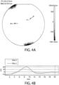
- Figures 4A and 4B show an interferometer map and surface elevation trace, respectively, for a wafer chuck of Example 1 featuring a "trench” and debris built up along the trench.
- the surface elevation traces of Figure 4B are taken along the lines identified in Figure 4A (the interferometer map) as "Slice1" and “Slice 2". Both of these slices show peaks or humps, corresponding to built-up debris. The accumulation of debris is typical or common in semiconductor processing.
- the wafer chuck supporting surface was then treated with the 6-axis machine of the present disclosure using a working head containing a treatment tool described above, and operated under the cleaning conditions described above.
- a working head containing a treatment tool described above was then treated with the 6-axis machine of the present disclosure using a working head containing a treatment tool described above, and operated under the cleaning conditions described above.
- only 2 of the 6 axes of the machine were used, namely, motions in a Cartesian coordinate system: X and Y directions at right angles to one another.
- FIG. 5 The results of this cleaning treatment are shown in Figure 5 .
- the figure shows an interference map for the entire wafer chuck surface in Figure 5A , and surface elevation traces for Slices 1 and 2 in Figure 5B .
- a number of features stand out regarding Figure 5B .
- the absence of a depression in Slice 2 indicates or suggests that the trench is present only on one side of the wafer chuck.
- the treatment tool of the present disclosure has been used successfully to clean debris off of the support surface of a wafer chuck using only motions of the tool in orthogonal X and Y-directions.
- prior art machines having X and Y-motion capabilities could be retrofitted with the treatment tool of the present disclosure to conduct similar cleaning/decontamination.
- prior art R-theta machines likewise could be retrofitted with the working head of Figure 3 to conduct this cleaning operation.
- the X and Y orthogonal motions of the treatment tool can be approximated with r and phi (or "B" axis) motions.
- every point in the X-Y cartesian coordinate system can be represented by specifying the r and phi coordinates. The smaller the increments of r and phi, the closer the approximation to X and Y orthogonal motion.
- the B axis rotation (phi) and the radial offset, r could be controlled by stepper motors, which could be controlled by programmable controllers.
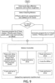
- Figure 9 provides a flowchart and block diagram for an automated cleaning operation.
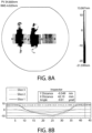
- This Example shows one use for the "dither" feature of the working head, and is made with reference to Figures 7 and 8 .
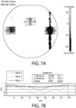
- Figures 7A and 7B show an interference map and surface elevation trace, respectively, for a wafer chuck of Example 2
- a "toroidal" shaped treatment tool having about the same hardness as the wafer chuck surface being processed was moved back and forth along a single axis (for example, the "Y" axis with an applied pressure and velocity appropriate for profiling (changing surface elevation).
- the toroidal shape means that the contact region between the treatment tool and the wafer chuck was a circle.
- a surface elevation profile was then made of a "slice" of the wear path. A total of three such wear tracks and slices were made. The results are displayed as the interference map of Figures 7A and the surface elevation traces of Figure 7B , respectively.
- Slice 2 showed the greatest amount of material removed from the chuck surface, as evidenced both by the darkest wear path in the interference map, as well as by the deepest trace of the three slices in the surface elevation plots of Figure 7B . Moreover, the cross-section of the wear path exhibits something resembling a "W" shape: moving away from the deepest part of the wear path, the elevation first levels out somewhat before continuing to rise to join up with the unaffected part of the wafer chuck adjacent to the wear track.
- FIGS 8A and 8B now show what happens when dither is applied to the treatment tool.
- the above test was repeated on a new, flat wafer chuck surface. Except for the application of dither, all of the operating parameters were kept the same as before. All three slices of the three wear tracks show significant wear (removal) of wafer chuck material. However, the cross-section of the wear tracks is much different. The "shoulders" are now gone, and each wear track has a cross-section resembling a shallow "U" shape, or closer to a Gaussian which is smoother function so as to not impart the undulations of the 'W'.
- the working head or treatment tool is sufficiently small in effective diameter it can be used to treat surfaces at different elevations. This is useful because in a wafer chuck having a seal ring, and pins, the seal ring is at a lower elevation than are the pin tops. A sufficiently small tool will fit within the width of the seal groove. Before treating the seal groove, however, the tool can be used to process the pin tops, for example, to correct flatness and to impart the required degree of roughness. This would be performed at relatively high application pressures. If this treatment is conducted deterministically and if the elevation map produced by the interferometer does not show too much area requiring grinding or lapping, the small diameter tool will be adequate to the task without taking too long to treat the area(s). After the tool finishes the grinding/lapping treatment, it can then be moved into the seal groove, and move circumferentially along the seal ring groove. At light application pressures, it will remove contamination but not remove substrate material, which would create additional contamination.
- the "theta” and “phi” rotational axes of the instant machine typically are separate, distinct axes. As such, the treatment tool can be positioned over the center of the work piece, permitting this region of the work piece to be processed. In contrast, the treatment tool of the R-theta two degrees-of-freedom machine of the prior art cannot process this central region.
Description
- The instant disclosure pertains to machines that have a treatment tool for processing (e.g., grinding/lapping/polishing/texturing) a work piece so that a surface of the work piece has a desired elevation or profile (i.e., a "figure"), and desired texture (roughness/smoothness). The treatment tool may be part of a larger working head assembly.
- Chucks, such as pin chucks, are used to hold flat components for processing. The most common use is to hold wafers (Si, SiC, GaAs, GaN, Sapphire, other) during processing to yield a semiconductor device. Other uses include holding substrates during the fabrication of flat panel displays, solar cells and other such manufactured products. These chucking components are known by many names, including wafer chucks, wafer tables, wafer handling devices, etc.
- The use of pins on these devices is to provide minimum chuck-to-substrate contact. Minimum contact reduces contamination and enhances the ability to maintain high flatness. The pin tops need to have low wear in use to maximize life and precision. The pin tops also need to be low friction so the substrate easily slides on and off, and lies flat on the pins.
- A pin chuck consists of a rigid body with a plurality of pins on the surface on which the substrate to be processed (e.g., Si wafer) rests. The pins exist in many geometries, and go by many names including burls, mesas, bumps, proud lands, proud rings, etc.
- Regardless of whether the chuck is of the "pin" type or not, the surface that supports whatever is to be chucked (e.g., a semiconductor wafer) needs to be flat to a very high degree of precision. In the case of semiconductor lithography, the flatness is measured in nanometers (nm).
- Machines exist, for example, those used in a "deterministic" fashion, to locally correct errors in flatness (surface elevation). Some techniques for this deterministic correction include, but not limited to, Ion Beam Figuring (IBF), Magneto Rheological Finishing (MRF), and computer controlled polishing (CCP). As used herein, the phrase "deterministic correction" means that figure, elevation or roughness data as measured for example, by an interferometer or profilometer, is fed into a finishing machine such as a lapping machine. The input may consist of one or more algorithms for optimizations such as convolution or transforms to optimize the tool path or footprint in such a manner that the machine most rapidly converges to the desired target shape with a minimal amount of time, cost or risk. It effectively treats those areas of the work piece that are in error and need processing (e.g., grinding, lapping or texturing), while minimizing the effort spent working on areas that are not in need or alteration. The machine does not automatically treat the entire surface of the work piece.
- The instant disclosure is not limited to machines that operate deterministically, but it will focus on those that employ physical contact of a tool here termed a "treatment tool" with the surface of a work piece to be processed to physically remove material from the work piece through grinding, lapping, texturing and/or polishing.
-
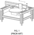
Figure 1 illustrates an example of a prior art machine. The work piece is mounted on a shaft "theta" that rotates, while treatment tool is mounted on a fixture that can move radially R with respect to the theta rotating axis. Thus, there are here two degrees of freedom of the treatment tool relative to the work piece: radius, denoted by "R", and rotation of the work piece, denoted by "theta". - One problem with this "R-theta" arrangement is that the treatment tool cannot process regions on the work piece that are very close to, or at, the center of the theta axis.
- The machine of the instant disclosure addresses this problem, and provides a solution.
-
DE 196 49 216 A1 is the basis for the preamble ofclaim 1 and discloses a method that involves pressing a workpiece against a rotation disk. The workpiece is rotated about a centre of rotation. The centre of rotation is offset relative to a centre of rotation of the disk. Also the workpiece or the disk undergo a revolution about a centre of revolution which is offset relative to the centres of rotation of the workpiece and the disk. The surface of the workpiece is treated by two rotations and one revolution. The apparatus for carrying out the method has a table for holding and rotating the disk. It also has a workpiece table for holding and rotating the workpiece. The disk may be a cup shaped grinding disk. -
US 2004/116058 A1 discloses a precision sub-aperture polishing tool that has a compliant, toroidal polishing member mountable to a support member. A circumferential portion of the polishing member extends uniformly beyond the peripheral surface of the support member and forms a clearance with the work piece surface during polishing operations. -
US 2004/092217 A1 discloses a wear ring assembly for use in a workpiece (e.g. a semiconductor wafer) polishing apparatus. The wear ring assembly comprises a wear element and a backing ring. The backing ring includes a fulcrum and is configured to transfer a component of pressure applied to the backing ring to the wear element via the fulcrum. In this manner, a substantially uniform vertical displacement of the wear ring is achieved. - The invention is set out in the independent claim.
- A machine featuring a treatment tool that contacts the surface of a work piece to grind that surface to a desired profile, impart a desired roughness to that surface, and remove contamination from the surface. The machine is configured to control multiple independent input variables simultaneously, the controllable variables selected from the group consisting of (i) velocity, (ii) rotation, and (iii) dither of the treatment tool, and (iv) pressure of the treatment tool against the surface. The machine can move the treatment tool with six degrees of freedom.
-
-
Figure 1 is a prior art machine showing a simple R - theta geometry -
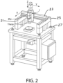
Figure 2 is an embodiment of the machine of the present disclosure showing 6 degrees of freedom holding the tool and work piece -
Figure 3 is a cross-sectional schematic view of the working head that can be used in connection with the instant machine. -
Figures 4A and 4B show an interferometer map and surface elevation trace, respectively, for a wafer chuck of Example 1 featuring a "trench" and debris built up along the trench. -
Figures 5A and 5B show an interferometer map and surface elevation trace, respectively, for the wafer chuck of Example 1 following a cleaning treatment. -
Figure 6 is a graph of r-phi coordinates superimposed on X-Y Cartesian coordinates, showing that every point in the Cartesian coordinate system can be described by coordinates given in the r-phi system, thus emulating machines that move exclusively in a cartesian manner such as a stepper. -
Figures 7A and 7B show an interference map and surface elevation trace, respectively, for a wafer chuck of Example 2 exhibiting a "W" shaped wear profile. -
Figures 8A and 8B show an interference map and surface elevation trace, respectively, for the wafer chuck of Example 2 showing how dither of the treatment tool ameliorates the "W" shaped wear profile. -
Figure 9 is a flowchart showing how a cleaning operation may be automated. - A machine having a treatment tool that grinds a surface to a desired profile imparts a desired roughness to that surface, and removes contamination in a single operation. The treatment tool, which may be part of a larger assembly sometimes referred to as a "working head", features a flat surface configured to contact and abrade the surface of the work piece as the treatment tool passes over it. The treatment tool may have about the same hardness as the work piece. Visually, the treatment tool may have the appearance of a disc. Alternatively, it may appear as an annulus, ring or toroid. If shaped as an annulus or ring or toroid, the space inside or within the annular space may contain a second treatment tool. Further, the treatment tool may feature a plurality of rings or toroids gathered or assembled together, and collectively defining a common flat surface.
- The machine may be operated or programmed to function or respond deterministically to inputted data such as interferometer or profilometer data reporting on the elevation and/or roughness of a surface. In response to this inputted data, the machine directs the treatment tool to operate only on those spots or regions of the surface that require treatment.
- In a first aspect of the disclosure, the treatment tool may have a number of degrees of freedom. First, it translates in three dimensions along three orthogonal axes. Next, it may be mounted or attached to a shaft that can rotate. Further, the treatment tool can be mounted on the rotational axis of the shaft, or it can be mounted off-axis; that is, it can be mounted a certain distance away radially from said axis. Still further, the treatment tool can move radially with respect to the rotational axis. Additionally, the machine can be configured to impart "dither" to the treatment tool.
- These degrees of freedom may be better illustrated with respect to the drawings.
-
Figure 1 illustrates a prior art machine. Here, there are two degrees of freedom: radius, denoted by "R", and rotation of the work piece, denoted by "theta". - The machine of the present disclosure also has these two degrees of freedom, as depicted in
Figure 2 . In addition, the present machine may translate the treatment tool and tool in three dimensions, for example, along "x", "y" and "z" axes, which may be orthogonal to each other. Next, it may be mounted or attached to a shaft that can rotate. Such rotation may be designated as "phi". Thus, the present machine has four additional degrees of freedom beyond the two identified in the prior art machine ofFigure 1 . The priority document to the instant patent application contains a photograph of the machine. - Power for the various motions may be supplied by electric motor(s), which may be stepping motors or linear motors or common the art.
Rails -
Figure 3 is a cross-sectional schematic view of a "working head" 30 that can be used in connection with the instant machine.Treatment tool 134 is attached toshaft 138 whose longitudinal axis may be termed the "U" axis. The attachment may be one of minimal constraint, such as a ball-and-socket joint 136, or it may be at least rotationally constrained so thattreatment tool 134 rotates when the U axis rotates. The U axis does not apply pressure of the treatment tool against the work piece. Rather, this pressure is applied bydead weight load 131. Rotational movement of the workinghead 30 is provided byinput shaft 130 which defines an axis termed the "B" axis. The U axis and the B axis are firmly connected to one another through Uaxis adjustment block 132. This adjustment block is slotted on the bottom to allow offset adjustment of the U axis relative to the B axis. This is shown by means ofadjuster screw 133. The adjuster screw may be adjusted so that the U and B axes are perfectly aligned (co-axial), or offset by an amount r (the radial offset). - Additionally, the machine can be configured to impart "dither" to the treatment tool. The nature of the dither can be random, orbital or linear. One way to impart such dither to the treatment tool is to adjust the adjuster screw so that the U axis is slightly offset from the B axis (slight amount of r), allowing the toroid to circulate in a manner such that the footprint over an undulation or dither is more controlled and smooth.
- The treatment tool is 27 mm in diameter. By outward appearance, it is a disc, but in reality it has a toroidal shape so that when it is brought into contact with the flat surface, the area of contact is not that of a disc but instead is a circle.
- The same treatment tool may be used in cleaning, profiling and roughening modes, depending upon how the tool is used. For example, given a 27mm diameter tool fabricated from reaction bonded silicon carbide, for cleaning debris off of a wafer chuck of similar hardness, a dead weight loading of 5-50 grams, and a tool velocity of 5-30 mm/sec may be used. For profiling (e.g., flattening) a surface, the loading may be 100-175 grams, and the tool velocity may be 20-50 mm/sec. For imparting surface roughness, the tool loading may be in excess of 150 grams, and the tool velocity relative to the surface being processed may be 20-50 mm/sec.
- The treatment tool may be provided in different sizes (diameter or effective diameter), depending on the size of the features or region on the work piece to be processed. For example, a smaller diameter treatment tool (for example, about 10 mm) may be used to treat recessed regions on a wafer chuck, such as the vacuum seal ring on a vacuum chuck.
- Moreover, the machine can be configured to house more than one working head, and have a tool changer to swap out one working head for a different one.
- In addition to the spatial degrees of freedom, and in a second aspect of the disclosure, the machine can be designed or programmed to respond to a number of other independent variables, which variables can be inputted to the machine simultaneously. In particular, the pressure that the treatment tool applies against the surface to be treated can be controlled, as can the amplitude and frequency of treatment tool dither.
Figures 2 and3 show the tool being mounted at a distance radius "r" from the center of the rotational shaft. Since "r" is one of the degrees of freedom, so the machine can move the tool along this radius. Additionally, the velocity of the treatment tool can be controlled, both in terms of the angular or rotational velocity of the shaft, as well as the translational velocity along the radius, and the translational velocity along the x, y and z axes. - The treatment tool component of the working head may be minimally constrained. That is, its orientation with respect to the surface to be treated is not fixed or prescribed. Rather, the treatment tool orients itself, or conforms to the surface, once it is brought into contact with the surface to be treated.
- In a second aspect of the disclosure, existing machines can be modified with a "bolt-on" module to upgrade the capabilities of other machines machine. The module would be incorporated into an existing precision machine tool, such as a semiconductor lithography machine. This would allow the user of the tool to in-situ correct the wafer chucks without removing them from the lithography machine. This would reduce cost, enhance productivity, and allow real-time correction to constantly maintain like-new precision. For example, the treatment tool of the existing machine can be replaced with the Applicant's minimally constrained treatment tool. To further assist in having the treatment tool conform to the surface to be treated, the tool can be provided where the contacting surface is in the form of a toroid. A further upgrade may include replacing the existing treatment tool with one having about the same hardness as the work piece. For example, if the work piece is a silicon carbide (SiC) wafer chuck, the substitute treatment tool can be made of SiC, or contain SiC, such as in the form of reaction-bonded SiC. A still further upgrade may include replacing the rotating treatment tool of a prior art machine with the working head of the present disclosure. Among the advantages flowing from this retrofit is the ability to apply dither, as well as the ability to approximate Cartesian (X-Y) motions using radial and rotational motions (r-phi), to be discussed in further detail below.
- Moreover, since Applicant has discovered that changing the pressure at which the treatment tool contacts the surface to be treated changes the mode of operation from de-contamination to processing, that is, grinding and/or modifying surface roughness, the bolt-on module includes a means for changing the application pressure of the treatment tool. The means for controlling the pressure could be in the form of software. Again, the application pressure can be controllably changed as a function of time and/or location of the treatment tool on the surface being treated. Another upgrade may consist of the module providing software or other instructions to the machine to controllably vary the velocity of translation or rotation of the treatment tool.
- Aspects of the present disclosure will now be described with reference to the following examples.
- This Example shows how a treatment tool of the present disclosure can be used to clean debris off of the support surface of a wafer chuck using only X and Y orthogonal motions of the treatment tool.
-
Figures 4A and 4B show an interferometer map and surface elevation trace, respectively, for a wafer chuck of Example 1 featuring a "trench" and debris built up along the trench. In particular, the surface elevation traces ofFigure 4B are taken along the lines identified inFigure 4A (the interferometer map) as "Slice1" and "Slice 2". Both of these slices show peaks or humps, corresponding to built-up debris. The accumulation of debris is typical or common in semiconductor processing. - The wafer chuck supporting surface was then treated with the 6-axis machine of the present disclosure using a working head containing a treatment tool described above, and operated under the cleaning conditions described above. However, only 2 of the 6 axes of the machine were used, namely, motions in a Cartesian coordinate system: X and Y directions at right angles to one another.
- The results of this cleaning treatment are shown in
Figure 5 . Again, the figure shows an interference map for the entire wafer chuck surface inFigure 5A , and surface elevation traces forSlices Figure 5B . A number of features stand out regardingFigure 5B . First, the peaks or humps have been eliminated, indicating successful removal of debris. Second, the depression inSlice 1 reveals the presence of a trench in the wafer chuck surface. Third, the absence of a depression inSlice 2 indicates or suggests that the trench is present only on one side of the wafer chuck. - Thus, the treatment tool of the present disclosure has been used successfully to clean debris off of the support surface of a wafer chuck using only motions of the tool in orthogonal X and Y-directions. Thus, prior art machines having X and Y-motion capabilities could be retrofitted with the treatment tool of the present disclosure to conduct similar cleaning/decontamination.
- In addition, prior art R-theta machines likewise could be retrofitted with the working head of
Figure 3 to conduct this cleaning operation. Specifically, and as depicted inFigure 6 , the X and Y orthogonal motions of the treatment tool can be approximated with r and phi (or "B" axis) motions. Specifically, every point in the X-Y cartesian coordinate system can be represented by specifying the r and phi coordinates. The smaller the increments of r and phi, the closer the approximation to X and Y orthogonal motion. Here, the B axis rotation (phi) and the radial offset, r, could be controlled by stepper motors, which could be controlled by programmable controllers.Figure 9 provides a flowchart and block diagram for an automated cleaning operation. - This Example shows one use for the "dither" feature of the working head, and is made with reference to
Figures 7 and8 . -
Figures 7A and 7B show an interference map and surface elevation trace, respectively, for a wafer chuck of Example 2 - A "toroidal" shaped treatment tool having about the same hardness as the wafer chuck surface being processed was moved back and forth along a single axis (for example, the "Y" axis with an applied pressure and velocity appropriate for profiling (changing surface elevation). Again, the toroidal shape means that the contact region between the treatment tool and the wafer chuck was a circle. A surface elevation profile was then made of a "slice" of the wear path. A total of three such wear tracks and slices were made. The results are displayed as the interference map of
Figures 7A and the surface elevation traces ofFigure 7B , respectively. -
Slice 2 showed the greatest amount of material removed from the chuck surface, as evidenced both by the darkest wear path in the interference map, as well as by the deepest trace of the three slices in the surface elevation plots ofFigure 7B . Moreover, the cross-section of the wear path exhibits something resembling a "W" shape: moving away from the deepest part of the wear path, the elevation first levels out somewhat before continuing to rise to join up with the unaffected part of the wafer chuck adjacent to the wear track. -
Figures 8A and 8B now show what happens when dither is applied to the treatment tool. The above test was repeated on a new, flat wafer chuck surface. Except for the application of dither, all of the operating parameters were kept the same as before. All three slices of the three wear tracks show significant wear (removal) of wafer chuck material. However, the cross-section of the wear tracks is much different. The "shoulders" are now gone, and each wear track has a cross-section resembling a shallow "U" shape, or closer to a Gaussian which is smoother function so as to not impart the undulations of the 'W'. - A single working head or treatment tool can grind, impart roughness, and remove contamination such as grinding debris from a surface to be treated. This is so because a light pressure will remove the contamination but will not modify the profile or alter the roughness of the surface. Higher pressures result in removal of substrate material from the surface being treated, not just contamination.
- If the working head or treatment tool is sufficiently small in effective diameter it can be used to treat surfaces at different elevations. This is useful because in a wafer chuck having a seal ring, and pins, the seal ring is at a lower elevation than are the pin tops. A sufficiently small tool will fit within the width of the seal groove. Before treating the seal groove, however, the tool can be used to process the pin tops, for example, to correct flatness and to impart the required degree of roughness. This would be performed at relatively high application pressures. If this treatment is conducted deterministically and if the elevation map produced by the interferometer does not show too much area requiring grinding or lapping, the small diameter tool will be adequate to the task without taking too long to treat the area(s). After the tool finishes the grinding/lapping treatment, it can then be moved into the seal groove, and move circumferentially along the seal ring groove. At light application pressures, it will remove contamination but not remove substrate material, which would create additional contamination.
- The "theta" and "phi" rotational axes of the instant machine typically are separate, distinct axes. As such, the treatment tool can be positioned over the center of the work piece, permitting this region of the work piece to be processed. In contrast, the treatment tool of the R-theta two degrees-of-freedom machine of the prior art cannot process this central region.
- An artisan of ordinary skill will appreciate that various modifications may be made to the disclosure herein described without departing from the scope of the disclosure as defined in the appended claims.
Claims (12)
- A machine comprising a treatment tool (134) that is configured to, in a single operation, grind a surface to a desired profile, impart a desired roughness to the surface, and remove contamination from the surface, said machine comprising means for translating said treatment tool in three dimensions along orthogonal axes, characterized in that said treatment tool comprising a contacting surface having a toroidal shape such that, when the treatment tool is brought into contact with a flat surface, the contact region between the contacting surface of the treatment tool and the flat surface is a circle.
- The machine of claim 1, wherein said treatment tool is a single tool.
- The machine of claim 1, configured to operate on the surface deterministically by responding to inputted data comprising at least one of interferometer or profilometer data reporting on the elevation and/or roughness of the surface, whereby said machine treats those areas of the work piece that are in error and need processing, and does not automatically treat the entire surface of the work piece.
- The machine of claim 1, wherein said treatment tool has an attachment to said machine such that said treatment tool is minimally constrained, wherein said attachment comprises a ball-and-socket joint (136).
- The machine of claim 1, further comprising means for controlling a pressure of said treatment tool against the surface.
- The machine of claim 5, wherein said pressure is controlled as a function of at least one of (i) time and (ii) location of said treatment tool on the surface.
- The machine of claim 1, further comprising a means for imparting dither to said treatment tool.
- The machine of claim 1, wherein said treatment tool is sufficiently small in effective diameter as to be able to process a second surface that is at a different elevation than a first surface.
- The machine of claim 1, wherein said treatment tool has the approximate same hardness as that of the work piece.
- The machine of claim 1, wherein said treatment tool comprises silicon carbide.
- The machine of claim 1, wherein said treatment tool is attached to a shaft that is configured to rotate.
- The machine of claim 11, wherein said treatment tool is attached to a rotational axis of said shaft, wherein the machine is configured to move the treatment tool radially with respect to the rotational axis.
Applications Claiming Priority (2)
| Application Number | Priority Date | Filing Date | Title |
|---|---|---|---|
| US201562205648P | 2015-08-14 | 2015-08-14 | |
| PCT/US2016/046439 WO2017030874A1 (en) | 2015-08-14 | 2016-08-11 | Machine for finishing a work piece, and having a highly controllable treatment tool |
Publications (3)
| Publication Number | Publication Date |
|---|---|
| EP3334561A1 EP3334561A1 (en) | 2018-06-20 |
| EP3334561A4 EP3334561A4 (en) | 2019-07-31 |
| EP3334561B1 true EP3334561B1 (en) | 2023-12-20 |
Family
ID=58051031
Family Applications (1)
| Application Number | Title | Priority Date | Filing Date |
|---|---|---|---|
| EP16837532.7A Active EP3334561B1 (en) | 2015-08-14 | 2016-08-11 | Machine for finishing a work piece, and having a highly controllable treatment tool |
Country Status (4)
| Country | Link |
|---|---|
| US (3) | US10702968B2 (en) |
| EP (1) | EP3334561B1 (en) |
| JP (1) | JP6831835B2 (en) |
| WO (1) | WO2017030874A1 (en) |
Families Citing this family (8)
| Publication number | Priority date | Publication date | Assignee | Title |
|---|---|---|---|---|
| JP6831835B2 (en) * | 2015-08-14 | 2021-02-17 | エム キューブド テクノロジーズ, インコーポレイテッド | Machines with highly controllable processing tools for finishing workpieces |
| JP6599832B2 (en) * | 2016-09-16 | 2019-10-30 | ファナック株式会社 | Machine tool and work plane machining method |
| CN107932283A (en) * | 2017-12-08 | 2018-04-20 | 马宁 | A kind of sanding apparatus for equipment of railway transportation |
| TWI722478B (en) * | 2019-07-05 | 2021-03-21 | 新代科技股份有限公司 | Grinding machine and optimization method for grinding map |
| CN110421412A (en) * | 2019-09-05 | 2019-11-08 | 河北工业大学 | A kind of small-sized magnetorheological plane polishing device |
| CN112045550A (en) * | 2020-09-15 | 2020-12-08 | 赖宗剑 | Mirror surface aluminum plate burnishing machine of polishing speed and dynamics adjustable |
| CN112589544B (en) * | 2020-12-09 | 2022-07-19 | 济南德洋低温科技有限公司 | Chemical container manufacturing and forming method |
| CN114102361A (en) * | 2021-11-25 | 2022-03-01 | 无锡工艺职业技术学院 | Ceramic part grinding method and grinding equipment |
Citations (1)
| Publication number | Priority date | Publication date | Assignee | Title |
|---|---|---|---|---|
| US20080125014A1 (en) * | 2006-11-29 | 2008-05-29 | William Rogers Rosch | Sub-aperture deterministric finishing of high aspect ratio glass products |
Family Cites Families (63)
| Publication number | Priority date | Publication date | Assignee | Title |
|---|---|---|---|---|
| US2926653A (en) * | 1958-09-18 | 1960-03-01 | Thompson Grinder Co | Grinding machines |
| US3500588A (en) * | 1966-12-05 | 1970-03-17 | Fred W Fischer | Surface grinder or related unit |
| US3623273A (en) * | 1970-03-10 | 1971-11-30 | Vyzk Ustav Mech | Apparatus for eccentric machining of electrodes |
| US4128968A (en) * | 1976-09-22 | 1978-12-12 | The Perkin-Elmer Corporation | Optical surface polisher |
| JPS6078254U (en) * | 1983-11-01 | 1985-05-31 | 株式会社東芝 | polishing equipment |
| GB8407058D0 (en) * | 1984-03-19 | 1984-04-26 | Black & Decker Inc | Attachments for power tools |
| US4956944A (en) * | 1987-03-19 | 1990-09-18 | Canon Kabushiki Kaisha | Polishing apparatus |
| JPH01156855U (en) * | 1988-04-20 | 1989-10-27 | ||
| US4956544A (en) * | 1988-07-26 | 1990-09-11 | Hotwatt Inc. | Overheat protected electric cartridge heater |
| FR2677276B1 (en) * | 1991-06-06 | 1995-12-01 | Commissariat Energie Atomique | POLISHING MACHINE WITH IMPROVED SAMPLE HOLDER TABLE. |
| FR2695853B1 (en) * | 1992-09-18 | 1994-11-25 | Thibaut Sa | Milling, planing and polishing machine with automatic tool change and corresponding device. |
| US5938504A (en) * | 1993-11-16 | 1999-08-17 | Applied Materials, Inc. | Substrate polishing apparatus |
| JPH07171747A (en) * | 1993-12-21 | 1995-07-11 | Ricoh Co Ltd | Grinding and polishing device |
| US5643053A (en) * | 1993-12-27 | 1997-07-01 | Applied Materials, Inc. | Chemical mechanical polishing apparatus with improved polishing control |
| JPH08336741A (en) * | 1995-06-09 | 1996-12-24 | Tokyo Seimitsu Co Ltd | Method of grinding surface |
| JPH0936070A (en) | 1995-07-21 | 1997-02-07 | Nippon Steel Corp | Polishing device of semiconductor wafer |
| JP3664188B2 (en) * | 1995-12-08 | 2005-06-22 | 株式会社東京精密 | Surface processing method and apparatus |
| KR100264228B1 (en) | 1996-05-10 | 2000-12-01 | 미다라이 후지오 | Chemical mechanical polishing apparatus and method |
| US6413156B1 (en) * | 1996-05-16 | 2002-07-02 | Ebara Corporation | Method and apparatus for polishing workpiece |
| TW313535B (en) | 1996-10-11 | 1997-08-21 | United Microelectronics Corp | Eraser of vacuum chuck of a stepper |
| JPH10329012A (en) * | 1997-03-21 | 1998-12-15 | Canon Inc | Polishing device and polishing method |
| US5969972A (en) * | 1997-07-02 | 1999-10-19 | Motorola, Inc. | Method for manufacturing a semiconductor component and automatic machine program generator therefor |
| US6439986B1 (en) | 1999-10-12 | 2002-08-27 | Hunatech Co., Ltd. | Conditioner for polishing pad and method for manufacturing the same |
| JP3859937B2 (en) | 2000-06-02 | 2006-12-20 | 住友大阪セメント株式会社 | Electrostatic chuck |
| TW525221B (en) * | 2000-12-04 | 2003-03-21 | Ebara Corp | Substrate processing method |
| SG131737A1 (en) * | 2001-03-28 | 2007-05-28 | Disco Corp | Polishing tool and polishing method and apparatus using same |
| JP4202703B2 (en) * | 2002-09-20 | 2008-12-24 | Sumco Techxiv株式会社 | Polishing equipment |
| US6796887B2 (en) * | 2002-11-13 | 2004-09-28 | Speedfam-Ipec Corporation | Wear ring assembly |
| US20040116058A1 (en) * | 2002-12-13 | 2004-06-17 | Eastman Kodak Company | Sub-aperture compliant toroidal polishing element |
| JP2004235201A (en) * | 2003-01-28 | 2004-08-19 | Okamoto Machine Tool Works Ltd | Chemical mechanical polishing method in dry condition and device therefor for substrate |
| US7150677B2 (en) | 2004-09-22 | 2006-12-19 | Mitsubishi Materials Corporation | CMP conditioner |
| US7104342B2 (en) * | 2004-09-29 | 2006-09-12 | Berg Frederic P | Active rotational balancing system for orbital sanders |
| JP4756583B2 (en) | 2005-08-30 | 2011-08-24 | 株式会社東京精密 | Polishing pad, pad dressing evaluation method, and polishing apparatus |
| JP2007214502A (en) * | 2006-02-13 | 2007-08-23 | Oki Electric Ind Co Ltd | Semiconductor device and its manufacturing method |
| JP2007258240A (en) * | 2006-03-20 | 2007-10-04 | Tokyo Electron Ltd | Surface processing method |
| DE102006026467B4 (en) * | 2006-06-07 | 2018-06-28 | Texas Instruments Deutschland Gmbh | Device for grinding a wafer |
| JP2008124292A (en) * | 2006-11-14 | 2008-05-29 | Disco Abrasive Syst Ltd | Wafer positioning jig of processing apparatus |
| JP5099476B2 (en) | 2006-12-28 | 2012-12-19 | 株式会社ニコン | Cleaning apparatus and cleaning system, pattern forming apparatus, cleaning method and exposure method, and device manufacturing method |
| US8740670B2 (en) * | 2006-12-28 | 2014-06-03 | Saint-Gobain Ceramics & Plastics, Inc. | Sapphire substrates and methods of making same |
| JP4864757B2 (en) * | 2007-02-14 | 2012-02-01 | 東京エレクトロン株式会社 | Substrate mounting table and surface treatment method thereof |
| JP5018249B2 (en) | 2007-06-04 | 2012-09-05 | 株式会社ニコン | Cleaning device, cleaning method, exposure apparatus, and device manufacturing method |
| JP2009043931A (en) * | 2007-08-08 | 2009-02-26 | Disco Abrasive Syst Ltd | Rear-surface grinding method for wafer |
| JP2009094326A (en) * | 2007-10-10 | 2009-04-30 | Disco Abrasive Syst Ltd | Method of grinding wafer |
| JP2010153407A (en) | 2008-12-23 | 2010-07-08 | Nikon Corp | Cleaning method and device, and exposure method and device |
| JP5275016B2 (en) * | 2008-12-25 | 2013-08-28 | 株式会社ディスコ | Grinding equipment |
| US8588956B2 (en) * | 2009-01-29 | 2013-11-19 | Tayyab Ishaq Suratwala | Apparatus and method for deterministic control of surface figure during full aperture polishing |
| NL2004153A (en) * | 2009-02-24 | 2010-08-25 | Asml Netherlands Bv | Lithographic apparatus, a method for removing material of one or more protrusions on a support surface, and an article support system. |
| US20100330890A1 (en) | 2009-06-30 | 2010-12-30 | Zine-Eddine Boutaghou | Polishing pad with array of fluidized gimballed abrasive members |
| JP5796412B2 (en) * | 2011-08-26 | 2015-10-21 | 三菱電機株式会社 | Manufacturing method of semiconductor device |
| KR101593117B1 (en) * | 2011-10-26 | 2016-02-11 | 케이테크 가부시키가이샤 | Grinding tool with eccentric rotation shaft |
| US9358660B2 (en) * | 2011-11-07 | 2016-06-07 | Taiwan Semiconductor Manufacturing Company, Ltd. | Grinding wheel design with elongated teeth arrangement |
| US9138855B2 (en) * | 2012-01-19 | 2015-09-22 | Dalian University of Technology School of Mechanical Engineering | Multifunctional substrate polishing and burnishing device and polishing and burnishing method thereof |
| EP3550364A1 (en) | 2012-02-03 | 2019-10-09 | ASML Netherlands B.V. | Substrate holder, lithographic apparatus and method of manufacturing a substrate holder |
| JP2013162084A (en) * | 2012-02-08 | 2013-08-19 | Ulvac Japan Ltd | Electrostatic chuck regenerating method |
| JP6085152B2 (en) | 2012-11-22 | 2017-02-22 | 日本特殊陶業株式会社 | Vacuum chuck |
| JP6129551B2 (en) * | 2012-12-27 | 2017-05-17 | 株式会社ディスコ | Processing method of plate |
| WO2015050218A1 (en) * | 2013-10-02 | 2015-04-09 | 日本碍子株式会社 | Method for producing polished article |
| JP2014128877A (en) | 2014-03-03 | 2014-07-10 | Femutekku:Kk | Surface processing apparatus and method |
| JP6307022B2 (en) * | 2014-03-05 | 2018-04-04 | 東京エレクトロン株式会社 | Substrate processing apparatus, substrate processing method, and recording medium |
| DE102014003598B4 (en) * | 2014-03-17 | 2020-02-27 | Satisloh Ag | Device for grinding, fine grinding and / or polishing workpieces of optical quality, in particular spherical lens surfaces in fine optics |
| JP2017537480A (en) | 2014-11-23 | 2017-12-14 | エム キューブド テクノロジーズM Cubed Technologies | Manufacture and repair of wafer pin chuck |
| JP6831835B2 (en) * | 2015-08-14 | 2021-02-17 | エム キューブド テクノロジーズ, インコーポレイテッド | Machines with highly controllable processing tools for finishing workpieces |
| US10144106B2 (en) * | 2015-11-02 | 2018-12-04 | Lake Country Manufacturing, Inc. | Adjustable stroke mechanism for random orbital machine |
-
2016
- 2016-08-11 JP JP2018507626A patent/JP6831835B2/en active Active
- 2016-08-11 WO PCT/US2016/046439 patent/WO2017030874A1/en active Application Filing
- 2016-08-11 EP EP16837532.7A patent/EP3334561B1/en active Active
-
2017
- 2017-10-20 US US15/789,943 patent/US10702968B2/en active Active
-
2019
- 2019-11-20 US US16/689,892 patent/US11623319B2/en active Active
-
2023
- 2023-03-14 US US18/183,404 patent/US20230211453A1/en active Pending
Patent Citations (1)
| Publication number | Priority date | Publication date | Assignee | Title |
|---|---|---|---|---|
| US20080125014A1 (en) * | 2006-11-29 | 2008-05-29 | William Rogers Rosch | Sub-aperture deterministric finishing of high aspect ratio glass products |
Also Published As
| Publication number | Publication date |
|---|---|
| EP3334561A4 (en) | 2019-07-31 |
| WO2017030874A1 (en) | 2017-02-23 |
| JP6831835B2 (en) | 2021-02-17 |
| EP3334561A1 (en) | 2018-06-20 |
| US20180111246A1 (en) | 2018-04-26 |
| US20230211453A1 (en) | 2023-07-06 |
| US11623319B2 (en) | 2023-04-11 |
| JP2018531503A (en) | 2018-10-25 |
| US10702968B2 (en) | 2020-07-07 |
| US20200198089A1 (en) | 2020-06-25 |
Similar Documents
| Publication | Publication Date | Title |
|---|---|---|
| EP3334561B1 (en) | Machine for finishing a work piece, and having a highly controllable treatment tool | |
| JP2018531503A6 (en) | Machine with highly controllable processing tools for finishing workpieces | |
| US10242905B2 (en) | Wafer pin chuck fabrication and repair | |
| JP6955592B2 (en) | Methods, systems, and polishing pads for chemical mechanical polishing | |
| JP6459524B2 (en) | Composite grinding machine and grinding method | |
| CN109290876B (en) | Method for processing wafer | |
| US20150105005A1 (en) | Chemical mechanical polisher with hub arms mounted | |
| US9662762B2 (en) | Modifying substrate thickness profiles | |
| CN102264508A (en) | Device for grinding both sides of flat workpieces | |
| WO2016010865A1 (en) | Modifying substrate thickness profiles | |
| EP3334564B1 (en) | Method for deterministic finishing of a chuck surface | |
| EP3334560B1 (en) | Method for removing contamination from a chuck surface | |
| US9987724B2 (en) | Polishing system with pad carrier and conditioning station | |
| US20220143779A1 (en) | Polishing head with local wafer pressure | |
| KR20170087300A (en) | Edge grinding apparatus | |
| WO2023158526A1 (en) | Pad carrier assembly for horizontal pre-clean module | |
| JP2006263833A (en) | Moving body structure and grinder | |
| JPH09290360A (en) | Grinder | |
| JP2019005865A (en) | Workpiece processing method |
Legal Events
| Date | Code | Title | Description |
|---|---|---|---|
| STAA | Information on the status of an ep patent application or granted ep patent |
Free format text: STATUS: THE INTERNATIONAL PUBLICATION HAS BEEN MADE |
|
| PUAI | Public reference made under article 153(3) epc to a published international application that has entered the european phase |
Free format text: ORIGINAL CODE: 0009012 |
|
| STAA | Information on the status of an ep patent application or granted ep patent |
Free format text: STATUS: REQUEST FOR EXAMINATION WAS MADE |
|
| 17P | Request for examination filed |
Effective date: 20180313 |
|
| AK | Designated contracting states |
Kind code of ref document: A1 Designated state(s): AL AT BE BG CH CY CZ DE DK EE ES FI FR GB GR HR HU IE IS IT LI LT LU LV MC MK MT NL NO PL PT RO RS SE SI SK SM TR |
|
| AX | Request for extension of the european patent |
Extension state: BA ME |
|
| DAV | Request for validation of the european patent (deleted) | ||
| DAX | Request for extension of the european patent (deleted) | ||
| RIC1 | Information provided on ipc code assigned before grant |
Ipc: B24B 1/00 20060101AFI20190314BHEP Ipc: H01L 21/302 20060101ALI20190314BHEP Ipc: B24B 37/005 20120101ALI20190314BHEP Ipc: H01L 21/304 20060101ALI20190314BHEP |
|
| A4 | Supplementary search report drawn up and despatched |
Effective date: 20190702 |
|
| RIC1 | Information provided on ipc code assigned before grant |
Ipc: B24B 1/00 20060101AFI20190626BHEP Ipc: H01L 21/302 20060101ALI20190626BHEP Ipc: B24B 37/005 20120101ALI20190626BHEP Ipc: H01L 21/304 20060101ALI20190626BHEP |
|
| STAA | Information on the status of an ep patent application or granted ep patent |
Free format text: STATUS: EXAMINATION IS IN PROGRESS |
|
| 17Q | First examination report despatched |
Effective date: 20200605 |
|
| STAA | Information on the status of an ep patent application or granted ep patent |
Free format text: STATUS: EXAMINATION IS IN PROGRESS |
|
| STAA | Information on the status of an ep patent application or granted ep patent |
Free format text: STATUS: EXAMINATION IS IN PROGRESS |
|
| P01 | Opt-out of the competence of the unified patent court (upc) registered |
Effective date: 20230514 |
|
| GRAP | Despatch of communication of intention to grant a patent |
Free format text: ORIGINAL CODE: EPIDOSNIGR1 |
|
| STAA | Information on the status of an ep patent application or granted ep patent |
Free format text: STATUS: GRANT OF PATENT IS INTENDED |
|
| INTG | Intention to grant announced |
Effective date: 20230628 |
|
| GRAS | Grant fee paid |
Free format text: ORIGINAL CODE: EPIDOSNIGR3 |
|
| GRAA | (expected) grant |
Free format text: ORIGINAL CODE: 0009210 |
|
| STAA | Information on the status of an ep patent application or granted ep patent |
Free format text: STATUS: THE PATENT HAS BEEN GRANTED |
|
| AK | Designated contracting states |
Kind code of ref document: B1 Designated state(s): AL AT BE BG CH CY CZ DE DK EE ES FI FR GB GR HR HU IE IS IT LI LT LU LV MC MK MT NL NO PL PT RO RS SE SI SK SM TR |
|
| REG | Reference to a national code |
Ref country code: GB Ref legal event code: FG4D |
|
| REG | Reference to a national code |
Ref country code: CH Ref legal event code: EP |
|
| REG | Reference to a national code |
Ref country code: DE Ref legal event code: R096 Ref document number: 602016084881 Country of ref document: DE |
|
| REG | Reference to a national code |
Ref country code: IE Ref legal event code: FG4D |
|
| PG25 | Lapsed in a contracting state [announced via postgrant information from national office to epo] |
Ref country code: GR Free format text: LAPSE BECAUSE OF FAILURE TO SUBMIT A TRANSLATION OF THE DESCRIPTION OR TO PAY THE FEE WITHIN THE PRESCRIBED TIME-LIMIT Effective date: 20240321 |
|
| REG | Reference to a national code |
Ref country code: LT Ref legal event code: MG9D |