EP3333541A2 - Système de relevé - Google Patents
Système de relevé Download PDFInfo
- Publication number
- EP3333541A2 EP3333541A2 EP17191802.2A EP17191802A EP3333541A2 EP 3333541 A2 EP3333541 A2 EP 3333541A2 EP 17191802 A EP17191802 A EP 17191802A EP 3333541 A2 EP3333541 A2 EP 3333541A2
- Authority
- EP
- European Patent Office
- Prior art keywords
- images
- camera
- surveying
- points
- image
- Prior art date
- Legal status (The legal status is an assumption and is not a legal conclusion. Google has not performed a legal analysis and makes no representation as to the accuracy of the status listed.)
- Pending
Links
Images


Classifications
-
- G—PHYSICS
- G01—MEASURING; TESTING
- G01C—MEASURING DISTANCES, LEVELS OR BEARINGS; SURVEYING; NAVIGATION; GYROSCOPIC INSTRUMENTS; PHOTOGRAMMETRY OR VIDEOGRAMMETRY
- G01C15/00—Surveying instruments or accessories not provided for in groups G01C1/00 - G01C13/00
- G01C15/002—Active optical surveying means
- G01C15/004—Reference lines, planes or sectors
- G01C15/006—Detectors therefor
-
- G—PHYSICS
- G01—MEASURING; TESTING
- G01C—MEASURING DISTANCES, LEVELS OR BEARINGS; SURVEYING; NAVIGATION; GYROSCOPIC INSTRUMENTS; PHOTOGRAMMETRY OR VIDEOGRAMMETRY
- G01C11/00—Photogrammetry or videogrammetry, e.g. stereogrammetry; Photographic surveying
- G01C11/02—Picture taking arrangements specially adapted for photogrammetry or photographic surveying, e.g. controlling overlapping of pictures
-
- G—PHYSICS
- G01—MEASURING; TESTING
- G01C—MEASURING DISTANCES, LEVELS OR BEARINGS; SURVEYING; NAVIGATION; GYROSCOPIC INSTRUMENTS; PHOTOGRAMMETRY OR VIDEOGRAMMETRY
- G01C11/00—Photogrammetry or videogrammetry, e.g. stereogrammetry; Photographic surveying
- G01C11/04—Interpretation of pictures
-
- G—PHYSICS
- G01—MEASURING; TESTING
- G01C—MEASURING DISTANCES, LEVELS OR BEARINGS; SURVEYING; NAVIGATION; GYROSCOPIC INSTRUMENTS; PHOTOGRAMMETRY OR VIDEOGRAMMETRY
- G01C15/00—Surveying instruments or accessories not provided for in groups G01C1/00 - G01C13/00
- G01C15/002—Active optical surveying means
-
- G—PHYSICS
- G01—MEASURING; TESTING
- G01C—MEASURING DISTANCES, LEVELS OR BEARINGS; SURVEYING; NAVIGATION; GYROSCOPIC INSTRUMENTS; PHOTOGRAMMETRY OR VIDEOGRAMMETRY
- G01C25/00—Manufacturing, calibrating, cleaning, or repairing instruments or devices referred to in the other groups of this subclass
- G01C25/005—Manufacturing, calibrating, cleaning, or repairing instruments or devices referred to in the other groups of this subclass initial alignment, calibration or starting-up of inertial devices
-
- G—PHYSICS
- G01—MEASURING; TESTING
- G01S—RADIO DIRECTION-FINDING; RADIO NAVIGATION; DETERMINING DISTANCE OR VELOCITY BY USE OF RADIO WAVES; LOCATING OR PRESENCE-DETECTING BY USE OF THE REFLECTION OR RERADIATION OF RADIO WAVES; ANALOGOUS ARRANGEMENTS USING OTHER WAVES
- G01S19/00—Satellite radio beacon positioning systems; Determining position, velocity or attitude using signals transmitted by such systems
- G01S19/01—Satellite radio beacon positioning systems transmitting time-stamped messages, e.g. GPS [Global Positioning System], GLONASS [Global Orbiting Navigation Satellite System] or GALILEO
- G01S19/03—Cooperating elements; Interaction or communication between different cooperating elements or between cooperating elements and receivers
- G01S19/10—Cooperating elements; Interaction or communication between different cooperating elements or between cooperating elements and receivers providing dedicated supplementary positioning signals
-
- G—PHYSICS
- G01—MEASURING; TESTING
- G01S—RADIO DIRECTION-FINDING; RADIO NAVIGATION; DETERMINING DISTANCE OR VELOCITY BY USE OF RADIO WAVES; LOCATING OR PRESENCE-DETECTING BY USE OF THE REFLECTION OR RERADIATION OF RADIO WAVES; ANALOGOUS ARRANGEMENTS USING OTHER WAVES
- G01S19/00—Satellite radio beacon positioning systems; Determining position, velocity or attitude using signals transmitted by such systems
- G01S19/01—Satellite radio beacon positioning systems transmitting time-stamped messages, e.g. GPS [Global Positioning System], GLONASS [Global Orbiting Navigation Satellite System] or GALILEO
- G01S19/13—Receivers
- G01S19/14—Receivers specially adapted for specific applications
-
- G—PHYSICS
- G06—COMPUTING; CALCULATING OR COUNTING
- G06T—IMAGE DATA PROCESSING OR GENERATION, IN GENERAL
- G06T7/00—Image analysis
- G06T7/0002—Inspection of images, e.g. flaw detection
-
- G—PHYSICS
- G06—COMPUTING; CALCULATING OR COUNTING
- G06T—IMAGE DATA PROCESSING OR GENERATION, IN GENERAL
- G06T7/00—Image analysis
- G06T7/0002—Inspection of images, e.g. flaw detection
- G06T7/0004—Industrial image inspection
-
- G—PHYSICS
- G06—COMPUTING; CALCULATING OR COUNTING
- G06T—IMAGE DATA PROCESSING OR GENERATION, IN GENERAL
- G06T7/00—Image analysis
- G06T7/50—Depth or shape recovery
- G06T7/55—Depth or shape recovery from multiple images
- G06T7/579—Depth or shape recovery from multiple images from motion
-
- G—PHYSICS
- G06—COMPUTING; CALCULATING OR COUNTING
- G06T—IMAGE DATA PROCESSING OR GENERATION, IN GENERAL
- G06T7/00—Image analysis
- G06T7/70—Determining position or orientation of objects or cameras
-
- G—PHYSICS
- G06—COMPUTING; CALCULATING OR COUNTING
- G06T—IMAGE DATA PROCESSING OR GENERATION, IN GENERAL
- G06T7/00—Image analysis
- G06T7/97—Determining parameters from multiple pictures
-
- H—ELECTRICITY
- H04—ELECTRIC COMMUNICATION TECHNIQUE
- H04N—PICTORIAL COMMUNICATION, e.g. TELEVISION
- H04N23/00—Cameras or camera modules comprising electronic image sensors; Control thereof
- H04N23/50—Constructional details
- H04N23/51—Housings
-
- H—ELECTRICITY
- H04—ELECTRIC COMMUNICATION TECHNIQUE
- H04N—PICTORIAL COMMUNICATION, e.g. TELEVISION
- H04N23/00—Cameras or camera modules comprising electronic image sensors; Control thereof
- H04N23/50—Constructional details
- H04N23/55—Optical parts specially adapted for electronic image sensors; Mounting thereof
-
- H—ELECTRICITY
- H04—ELECTRIC COMMUNICATION TECHNIQUE
- H04N—PICTORIAL COMMUNICATION, e.g. TELEVISION
- H04N23/00—Cameras or camera modules comprising electronic image sensors; Control thereof
- H04N23/57—Mechanical or electrical details of cameras or camera modules specially adapted for being embedded in other devices
-
- H—ELECTRICITY
- H04—ELECTRIC COMMUNICATION TECHNIQUE
- H04N—PICTORIAL COMMUNICATION, e.g. TELEVISION
- H04N23/00—Cameras or camera modules comprising electronic image sensors; Control thereof
- H04N23/60—Control of cameras or camera modules
- H04N23/63—Control of cameras or camera modules by using electronic viewfinders
- H04N23/633—Control of cameras or camera modules by using electronic viewfinders for displaying additional information relating to control or operation of the camera
- H04N23/635—Region indicators; Field of view indicators
-
- H—ELECTRICITY
- H04—ELECTRIC COMMUNICATION TECHNIQUE
- H04N—PICTORIAL COMMUNICATION, e.g. TELEVISION
- H04N23/00—Cameras or camera modules comprising electronic image sensors; Control thereof
- H04N23/60—Control of cameras or camera modules
- H04N23/69—Control of means for changing angle of the field of view, e.g. optical zoom objectives or electronic zooming
-
- H—ELECTRICITY
- H04—ELECTRIC COMMUNICATION TECHNIQUE
- H04N—PICTORIAL COMMUNICATION, e.g. TELEVISION
- H04N23/00—Cameras or camera modules comprising electronic image sensors; Control thereof
- H04N23/60—Control of cameras or camera modules
- H04N23/698—Control of cameras or camera modules for achieving an enlarged field of view, e.g. panoramic image capture
-
- H—ELECTRICITY
- H04—ELECTRIC COMMUNICATION TECHNIQUE
- H04N—PICTORIAL COMMUNICATION, e.g. TELEVISION
- H04N23/00—Cameras or camera modules comprising electronic image sensors; Control thereof
- H04N23/90—Arrangement of cameras or camera modules, e.g. multiple cameras in TV studios or sports stadiums
-
- G—PHYSICS
- G06—COMPUTING; CALCULATING OR COUNTING
- G06T—IMAGE DATA PROCESSING OR GENERATION, IN GENERAL
- G06T2207/00—Indexing scheme for image analysis or image enhancement
- G06T2207/10—Image acquisition modality
- G06T2207/10028—Range image; Depth image; 3D point clouds
-
- G—PHYSICS
- G06—COMPUTING; CALCULATING OR COUNTING
- G06T—IMAGE DATA PROCESSING OR GENERATION, IN GENERAL
- G06T2207/00—Indexing scheme for image analysis or image enhancement
- G06T2207/30—Subject of image; Context of image processing
- G06T2207/30244—Camera pose
Definitions
- the present invention pertains to a surveying system comprising a camera module providing images for performing a SLAM- or SfM-algorithm.
- the invention describes a camera module which can be attached on a pole to a GNSS-antenna or a reflector for the measurement of points without the levelling step.
- the camera module enables the measurement of points where the GNSS-signal or the line-of-sight between total station and pole is interrupted.
- a point cloud of the environment can be derived.
- rectified views or orthophotos can be generated, e. g. of the terrain or a facade.
- the surveyor places the pole tip onto the measuring point, levels the pole and triggers the measurement.
- the levelling step takes some time and - if not carried out properly - leads to a degraded measurement result.
- Surveying with a GNSS-pole is only possible at places, where the signals of a sufficient number of GNSS satellites can be received. When the surveyor moves close to a building, some of the satellite signals may be not receivable anymore. Thus, at such a place a measurement is not possible at all.
- a GNSS surveying system can record absolute positions with good accuracy on a global scale, e. g. 2-4 cm. However, such a system can record only single points, where the operator must position the GNSS pole vertically on top of point to be measured. The derivation of a point cloud with a GNSS-pole is not state-of-the-art.
- US 2011/0064312 A1 relates to image-based geo-referencing and discloses a combination of GNSS measurements with image processing to provide new solutions for positioning.
- Stored geo-referenced images are compared (feature-correlated) with actual images made by a GNSS receiver. This is then used to qualify the accuracy of the GNSS measurement or complement missing parts (e.g. height information). It is also possible the other way round, i.e. the GNSS measurement is used to update the geo-reference of the stored images. This can also be used to determine a local coordinate system.
- US 2011/0157359 A1 discloses aligning a virtual perspective centre of a camera with the measurement (antenna) centre of a position measurement system. This facilitates computations in a combined image/GNSS system.
- WO 2011/163454 A1 discloses a method and apparatus for image-based positioning, tracking image features from one image to the next in order to determine the position change of a GNSS receiver using SLAM techniques.
- WO 2010/080950 A1 discloses determining orientation of a GNSS receiver from image data.
- One or more external portable computational devices e.g. smartphone, tablet PC, laptop
- the system has a cable or wireless connection with at least one of these computational devices.
- the data are transferred to these devices and all computations are automatically distributed between all available computational devices. All computational devices could communicate between each other.
- one advantage of such solution is an ability to use all available computational resources for fast in-field data processing or visualization. New devices could be easily added for computation without updating of the surveying device.
- One aspect of the invention relates to a surveying system adapted to determine positions of a position measuring resource being mounted on a surveying pole, particularly a GNSS-antenna or a retro-reflector, in a coordinate system of the surveying system, the surveying system comprising a surveying subsystem with a camera module (30) being attached to the surveying pole (10) and comprising at least one camera (31) for capturing images, and a control and evaluation unit (12) having stored a program with program code so as to control and execute an orientation determining functionality in which
- the surveying system further comprises a processing unit having stored a program with program code so as to control and execute a single point measurement functionality in which - upon a trigger -
- the orientation of the at least one camera is derived based on one or more of the determined poses and
- the orientation is derived in all three rotational degrees of freedom, in particular wherein position and orientation in six degrees of freedom are determined.
- an orientation of the surveying pole is derived based on the poses.
- the single point measurement functionality involves that a trigger-related section-wise bundle-adjustment is performed for the determination of the trigger-related external orientation, wherein - using only a subset of most recent images of the series of images, the subset particularly consisting of between the most actual 50 and the most actual 5 images - the reference point field and the poses within the range of the subset are retroactively re-calculated for the images of the subset and wherein these re-calculated poses are used for deriving the external orientation.
- the invention also relates to a surveying subsystem providing positional information of a surrounding in form of a scaled point cloud.
- the invention thus relates to a surveying subsystem comprising a camera module and a control and evaluation unit to be used as part of a surveying system that is adapted to determine positions of a position measuring resource being mounted on a hand-carried surveying pole, particularly wherein the position measuring resource comprises a GNSS-antenna or a retro-reflector.
- the camera module is designed to be attached to the surveying pole and comprises at least one camera for capturing images.
- the control and evaluation unit has stored a program with program code so as to control and execute a spatial representation generation functionality in which - when moving along a path through a surrounding -
- control and evaluation unit is configured so that the spatial representation generation functionality is controlled and executed in such a way, that the point cloud is generated
- control and evaluation unit is configured so that the spatial representation generation functionality is controlled and executed in such a way, that a graphical reproduction is generated for the scaled point cloud, the graphical reproduction being displayable by display means of the surveying system, thus providing for a direct feedback to a user about already acquired data, so that the already acquired data can be checked regarding its completeness.
- control and evaluation unit is configured so that the spatial representation generation functionality is controlled and executed in such a way, that position information is derived for a single point selected in at least one image of the series of images, wherein a subset of images with determined poses related to the selected point is automatically identified from the series of images, particularly all images in which the selected point appears, and the position information is calculated based on the subset, particularly after the point was manually selected by a user.
- control and evaluation unit is configured so that the spatial representation generation functionality is controlled and executed in such a way, that the point cloud is processed covering
- the invention also relates to a surveying subsystem comprising a camera module and a control and evaluation unit to be used as part of a surveying system that is adapted to determine positions of a position measuring resource being mounted on a surveying pole, particularly of a GNSS-antenna or of a retro-reflector, the camera module being designed to be attached to the surveying pole and comprising at least one camera for capturing images, the control and evaluation unit having stored a program with program code so as to control and execute a georeferencing functionality in which - when moving along a path through a surrounding -
- the georeferencing functionality comprises matching the orthophoto with a reference orthophoto for deriving position information of the surveying subsystem, in particular wherein the reference orthophoto
- the orthorectified orthophoto is generated by means of image stitching of at least two images of the series of images.
- the invention also relates to a camera module to be used as part of a surveying system that is adapted to determine positions of a position measuring resource being mounted on a surveying pole, particularly wherein the position measuring resource comprises a GNSS-antenna or a retro-reflector.
- the camera module is designed to be attached to the surveying pole and comprises two cameras arranged relative to each other with substantially diametrically opposing viewing directions, each of the two cameras having a fisheye lens and being adapted to capture wide panoramic images.
- the invention also relates to a surveying subsystem comprising a camera module and a control and evaluation unit.
- the camera module comprises at least one camera, the camera having a fisheye lens and being adapted to capture wide panoramic images.
- the control and evaluation unit has stored a program with program code so as to control and execute a spatial representation generation functionality in which - when moving along a path through a surrounding - a series of panoramic images of the surrounding is captured with the at least one camera, the series comprising an amount of panoramic images captured with different poses of the camera, the poses representing respective positions and orientations of the camera, a SLAM-evaluation with a defined algorithm using the series of panoramic images is performed, wherein a plurality of respectively corresponding image points are identified in each of several sub-groups of panoramic images of the series of panoramic images and, based on resection and forward intersection using the plurality of respectively corresponding image points, a reference point field is built up comprising a plurality of reference points of the surrounding, wherein coordinates of the reference points are derived,
- the cameras module comprises two cameras arranged relative to each other with substantially diametrically opposing viewing directions each of the two cameras having a fisheye lens and being adapted to capture wide panoramic images.
- control and evaluation unit is configured so that the spatial representation generation functionality is controlled and executed in such a way, that the poses for the panoramic images are determined by applying a defined optical imaging method taking account of the optical properties of the fisheye lens, in particular wherein different imaging planes are used with the optical imaging method and/or one of the following mapping functions is used:
- Calculation of the poses and/or a point cloud using images captured with such fisheye optics are performed using one of above methods in order to provide an exact projection of the reference points and thus to provide correct position and/or orientation information for the surrounding. With projecting the surrounding like that a distortion-free image of the surrounding can be provided.
- each of the two cameras has a field of view of at least 180° in the respective viewing directions regarding at least one axis, particularly in an azimuthal direction.
- Another aspect of the invention focuses on a specific camera module to be used as part of a surveying system that is adapted to determine positions of a position measuring resource being mounted on a surveying pole, particularly wherein the position measuring resource comprises a GNSS-antenna or a retro-reflector, wherein the camera module is designed to be attached to the surveying pole and comprises a camera and an optical element, the optical element being designed so that the camera has - in an azimuthal direction - an angle of view of 360°, particularly wherein the optical element comprises a mirroring surface in form of a cone, a sphere or a curvature.
- the optical element preferably may be embodied as a parabolic mirror.
- the camera and the optical element are arranged and designed so that a surrounding to be captured is projected onto a sensor of the camera so that an image of the surrounding is providable with identically sized pieces of the image basically covering identically sized parts of the surrounding, thus providing for an image representing the captured surrounding in homogenous reproduction.
- optical element e.g. parabolic mirror
- a camera as described provides for benefits to also be comparable with these regarding a combination of fisheye optics with a camera or at least two cameras. Additionally, a 360° panoramic view and capturing of corresponding images is realised with a single camera only, thus also providing for the use of only one camera.
- the invention also relates to a surveying subsystem comprising a camera module and a control and evaluation unit to be used as part of a surveying system that is adapted to determine positions of a position measuring resource being mounted on a surveying pole, particularly of a GNSS-antenna or of a retro-reflector.
- the camera module is designed to be attached to the surveying pole and comprising at least two cameras for capturing images.
- the control and evaluation unit has stored a program with program code so as to control and execute a panoramic image generation functionality in which - in response to a starting command -
- the panoramic image generation functionality comprises generating a combined stitched image from the synchronously captured images of the first and second camera.
- the position measuring resource comprises a GNSS-antenna
- the control and evaluation unit is configured so that - when moving along a path through the surrounding - the panoramic image generation functionality is controlled and executed in such a way, that
- control and evaluation unit is configured so that - when moving along a path through the surrounding - the panoramic image generation functionality is controlled and executed in such a way, that the starting command is released based on
- the subsystem comprises at least one optical triggering means that is perceivable by each of the at least two cameras, wherein the central optical trigger is a perceivable optical signal of the at least one optical triggering means, in particular wherein the optical triggering means comprises a flash light.
- the subsystem comprises at least one optical triggering means that is perceivable by the first and second camera, wherein the central optical trigger is a perceivable optical signal of the at least one optical triggering means, in particular wherein the optical triggering means comprises a light emitting diode.
- the invention also relates to a surveying subsystem comprising a camera module and a control and evaluation unit to be used as part of a surveying system that is adapted to determine positions of a position measuring resource being mounted on a surveying pole, particularly of a GNSS-antenna or of a retro-reflector.
- the camera module is designed to be attached to the surveying pole and comprises at least one camera for capturing images.
- the control and evaluation unit has stored a program with program code so as to control and execute an image triggering functionality in which - when moving along a path through a surrounding -
- the camera module comprises at least two cameras; the external trigger signal causes each of the at least two cameras to synchronously capture an image; and a combined stitched image is generated from the synchronously captured images of the at least two cameras.
- the subsystem comprises means for storing at least one pre-defined external trigger signal, wherein the at least one pre-defined external trigger signal comprises
- the invention also relates to a blurring functionality of of a surveying system.
- algorithms for face detection and detection of license plates on cars can be applied.
- the detected faces or license plates can then be made unrecognizable, e. g. by blurring the corresponding areas in the images and also in the point cloud.
- KLT Kanade-Lucas-Tomasi
- a surveying subsystem comprises a camera module and a control and evaluation unit to be used as part of a surveying system that is adapted to determine positions of a position measuring resource being mounted on a surveying pole, particularly of a GNSS-antenna or of a retro-reflector.
- the camera module is designed to be attached to the surveying pole and comprises at least one camera for capturing images.
- the control and evaluation unit has stored a program with program code so as to control and execute a data reduction functionality in which - when moving along a path through a surrounding -
- the 3D-positions are modified or deleted in such a way that individual characteristics of the identified objects are not identifiable in the computed point cloud.
- image data being connected to the identified objects in the image are modified or deleted, particularly in such a way that individual characteristics of the identified objects are not identifiable in the image.
- pre-defined kinds of objects comprise at least
- Another aspect of the invention focuses on privacy or secrecy protection when performing surveying tasks.
- taking pictures or videos is subject to approval of the owners or authorities or completely prohibited.
- Such areas are e. g. military facilities.
- all images taken for the computing of a point cloud are deleted directly after they have been used accordingly and are not needed any longer for computing the point cloud. Only a small number of images have to be stored at the same time for computing the point cloud.
- the images are deleted without delay after having been used for computing the point cloud, in particular wherein the images are deleted in such a way that no video stream can be created from the deleted images.
- the images are stored and deleted in such a way that not more than ten images are stored in the memory at the same time, in particular not more than five images.
- a surveying subsystem comprises a camera module and a control and evaluation unit to be used as part of a surveying system that is adapted to determine positions of a position measuring resource being mounted on a hand-carried surveying pole, particularly wherein the position measuring resource comprises a GNSS-antenna or a retro-reflector.
- the camera module is designed to be attached to the surveying pole and comprises at least one camera for capturing images.
- the control and evaluation unit has stored a program with program code so as to control and execute a spatial representation generation functionality in which - when moving along a path through a surrounding -
- control and evaluation unit is configured so that the spatial representation generation functionality is controlled and executed in such a way, that a moving object is recognised as the interfering object on basis of a motion detection algorithm, particularly by feature tracking.
- a person particularly the user carrying the pole, or a car is recognised as the interfering object.
- control and evaluation unit is configured so that the spatial representation generation functionality is controlled and executed in such a way that applying the steps of recognising the interfering object and fading out the interfering object is triggered by a user command.
- the user coarsely marks an object to be recognised as interfering object in at least one of the series of images, wherefore the at least one image is displayed on displays means.
- the detection and fading out of interfering objects provides for a faster data processing as less amount of image data has to be considered for determining poses. Furthermore, the calculated poses comprise a higher degree of precision as incorrect imaging - which would occur e.g. if considering a moving car in more images which were taken at different points in time - initially is suppressed.
- above method generally provides for better (particularly more precise and faster) matching and identification of reference points (image points in the images).
- the method may be executed automatically controlled by the control and evaluation unit or may be triggered by user, e.g. when the user marks a respective object in an image displayed on display means of the surveying system.
- a surveying subsystem comprises a camera module and a control and evaluation unit to be used as part of a surveying system that is adapted to determine positions of a position measuring resource being mounted on a surveying pole, particularly wherein the position measuring resource comprises a GNSS-antenna or a retro-reflector.
- the camera module is designed to be attached to the surveying pole and comprises at least one camera for capturing images.
- the position measuring resource comprises a reference pattern located at the housing of the measuring resource.
- the position measuring resource and the camera module are arranged in defined manner relative to each other so that the reference pattern appears in the field of view of the at least one camera.
- control and evaluation unit has stored a program with program code so as to execute a camera calibration functionality in which
- the reference pattern is embodied as a structured pattern being provided by a light source or as a permanent pattern.
- a verification of a desired position of the camera or the camera module, respectively, relative to the position measuring resource is enabled. If the reference pattern appears in a captured image according to a target appearance, the camera is positioned in an expected home position. In case the appearance of the pattern differs from an expected appearance the camera module is position and/or oriented different to a home position. A deviation of the position of the camera can be derived by comparing the reference image with the actually captured image, particularly by comparing the appearances of the patterns.
- the invention also relates to a surveying subsystem comprising a camera module and a control and evaluation unit to be used as part of a surveying system that is adapted to determine positions of a position measuring resource being mounted on a hand-carried surveying pole, particularly wherein the position measuring resource comprises a GNSS-antenna or a retro-reflector.
- the camera module is designed to be attached to the surveying pole and comprises at least one camera for capturing images.
- the position measuring resource and the camera module are arranged in defined manner relative to each other.
- the control and evaluation unit has stored a program with program code so as to control and execute a calibration functionality in which - when moving along a path through a surrounding -
- determined positions of the position measuring resource for points that have been adopted on the path are received by the control and evaluation unit from the surveying system, and calibration parameters regarding a fixed spatial relationship between the position measuring resource and the at least one camera are derived based on an interrelated assessment of the received determined positions and the determined poses.
- control and evaluation unit is configured so that the calibration functionality is controlled and executed in such a way, that trajectories according to the path are derived based on the derived poses and on the received determined positions, wherein the calibration parameters are derived based on comparing the trajectories.
- control and evaluation unit is configured so that the calibration functionality is controlled and executed in such a way that the calibration parameters are derived by additionally using data generated by an inertial measuring unit, the inertial measuring unit being associated with the surveying subsystem or the position measuring resource.
- the received positions of the position measuring resource are determined by receiving GNSS-signals on side of the position measuring resource or by reflecting a measuring laser beam on side of the position measuring resource, the measuring laser beam being emitted and received by a total station or a theodolite.
- the poses represent respective orientations of the camera. That method provides for a continuous and automatic position-calibration while moving the camera (and the position measuring resource accordingly). With help of data provided by the inertial measuring unit such calibration is enable with six degrees of freedom (6-DOF).
- the invention also relates to a surveying subsystem comprising a camera module and a control and evaluation unit to be used as part of a surveying system that is adapted to determine positions of a position measuring resource being mounted on a hand-carried surveying pole, particularly wherein the position measuring resource comprises a GNSS-antenna or a retro-reflector.
- the camera module is designed to be attached to the surveying pole and comprises at least one camera for capturing images.
- An inertial measuring unit is associated with the surveying subsystem or the position measuring resource in a fixed spatial relationship relative to the surveying subsystem.
- the control and evaluation unit has stored a program with program code so as to control and execute a calibration functionality in which - when moving along a path through a surrounding -
- control and evaluation unit is configured so that the calibration functionality is controlled and executed in such a way, that the inertial measuring unit is calibrated using the derived calibration parameters, wherein a systematic error of the inertial measuring unit is compensated, particularly wherein a bias of the inertial measuring unit is compensated.
- a calibration of the IMU is provided just (only) on basis of the orientation data derived from the poses of the images, i.e. derived from a series of images captured while moving the camera.
- Camera and IMU are arranged in defined relative spatial positions while moving.
- the invention also relates to a surveying subsystem comprising a camera module and a control and evaluation unit to be used as part of a surveying system that is adapted to determine positions with use of a surveying pole,
- the camera module is designed to be attached to the surveying pole in a known distance to a bottom end of the pole and comprises at least one camera for capturing images.
- the control and evaluation unit has stored a program with program code so as to control and execute a scaling functionality in which - when moving along a path through a surrounding -
- scaling the point cloud comprises determining 3D-positions of points on the ground based on the determined distance.
- determining the distance from the camera to the ground comprises deriving an orientation of the camera, in particular from the poses.
- another aspect concerning the invention relates to a bundle-adjustment for a surveying subsystem, the surveying subsystem comprising a camera module and a control and evaluation unit to be used as part of a surveying system that is adapted to determine positions of a position measuring resource being mounted on a hand-carried surveying pole, particularly wherein the position measuring resource comprises a GNSS-antenna or a retro-reflector.
- the camera module is designed to be attached to the surveying pole and comprises at least one camera for capturing images.
- the control and evaluation unit has stored a program with program code so as to control and execute a spatial representation generation functionality in which - when moving along a path through a surrounding - at least
- a point cloud comprising 3D-positions of points of the surrounding is computed by forward intersection using the images of the series of images, determined positions of the position measuring resource for points that have been adopted on the path are received by the control and evaluation unit from the surveying system, and on selection of a single point or a region in at least one of the images of the series of images, bundle-adjustment for refining the point cloud is performed based at least on image data of a pre-defined area around the point or of the region respectively and on information relating to the received determined positions.
- the overall solution (at least poses and point cloud) is refined using bundle-adjustment.
- This part of the algorithm is a non-linear least squares minimization of the re-projection error. It will optimise the location and orientation of respective camera positions and 3D-points.
- a part of gathered measuring data e.g. images, image points, poses and/or 3D-positions
- a refined (partial) point cloud referring to a part of the surrounding covered by the captured images.
- measuring data provided by a Kalman-Filter is used.
- measuring data according to a close measuring history is used, e.g. data corresponding to the preceding and/or successive ten poses (with respect to that image which the point or region of interest for bundle-adjustment is selected in).
- positional information is derivable from the measurement-trigger, and the subset is selected based on the positional information.
- the measurement-trigger is a trigger receivable from surveying system.
- the measurement-trigger is automatically caused by putting the pole on a measuring point and/or keeping the pole basically in fixed position and orientation for a pre-determined time period.
- the section-wise bundle-adjustment is performed by using non-linear least squares minimisation of errors occurring with identifying the image points and determining the poses.
- localization information related to the measurement-trigger is derived based on re-calculated poses, in particular wherein a position and orientation of the hand-carried surveying pole for one or more measurement-trigger-related points of time are derived.
- the point cloud is scaled with help of the received determined positions, and/or coordinates of a position of a tip of the surveying pole is derived and output in reaction upon the measurement-trigger after performance of the section-wise bundle-adjustment.
- Performing the bundle-adjustment provides very precise determination of a position of the selected point or, respectively, precise determination of an amount of points in a defined region and thus providing for an exact digital 3D-model of the defined region.
- an orientation of the pole - if calculated from the poses - may be determined in more precise manner. Particularly, such orientation is derived with six degrees of freedom (6-DOF) due to the computed poses.
- the bundle-adjustment particularly is performed when a user of the system selects the point or the region, wherein the adjusted data is provided to the user in real-time manner, i.e. the user selects the point and basically immediately receives the calculation results e.g. on display means of the system.
- a further inventive aspect relates to a specific camera module to be used as part of a surveying system that is adapted to determine positions of a position measuring resource being mounted on a surveying pole, particularly wherein the position measuring resource comprises a GNSS-antenna or a retro-reflector.
- That camera module is designed to be attached to the surveying pole and comprises at least a first and a second camera, the first camera comprising first imaging properties and the second camera comprising second imaging properties different from the first imaging properties.
- the first camera is designed so that images with an image resolutions lower than an image resolution of images capturable with the second camera are captured.
- the first camera comprises a first imaging sensor and the second camera comprises a second imaging sensor, wherein the first imaging sensor provides a lower point-to-point resolution regarding images to be captured compared with the second imaging sensor.
- the first camera is designed for capturing images with a higher frame rate compared to the second camera.
- the first camera is designed so that image capturing according to a first spectral range is provided
- the second camera is designed so that image capturing according to a second spectral range is provided, wherein the first spectral range differs from the second spectral range, in particular wherein the first camera provides image capturing according to an infrared spectral range or provides thermographical images.
- Capturing images with different spectral ranges provides for getting more detailed information of the covered surrounding, particularly for generation of images (e.g. by merging images of different spectral ranges covering common areas of the surrounding) with improved textures or extended information regarding spectral properties, e.g. regarding a thermal property of an object.
- the invention also related to a surveying subsystem comprising a camera module and a control and evaluation unit to be used as part of a surveying system that is adapted to determine positions of a position measuring resource being mounted on a hand-carried surveying pole, particularly wherein the position measuring resource comprises a GNSS-antenna or a retro-reflector.
- the camera module is designed to be attached to the surveying pole and comprises at least two cameras for capturing images, wherein a first of the at least two cameras is designed to capture first images with a lower image resolutions compared to second images capturable with a second of the at least two cameras.
- the control and evaluation unit has stored a program with program code so as to control and execute a spatial representation generation functionality in which - when moving along a path through a surrounding -
- control and evaluation unit is configured so that the spatial representation generation functionality is controlled and executed in such a way that based on the determined poses a point cloud comprising 3D-positions of points of the surrounding is computed as the spatial representation by forward intersection using images of the second series of images.
- processing of the point cloud is triggered by a user command.
- control and evaluation unit is configured so that the spatial representation generation functionality is controlled and executed in such a way, that processing of the point cloud is performed using a defined subset of images of the second series of images, wherein the subset is selectable by a user, thus providing for generating detailed 3D-inforamtion for a desired part of the surrounding in comparatively short time.
- control and evaluation unit is configured so that the spatial representation generation functionality is controlled and executed in such a way, that a dense matching algorithm is executed for providing the point cloud using images of the second series of images.
- control and evaluation unit is configured so that the spatial representation generation functionality is controlled and executed in such a way, that based on the determined poses, an initial point cloud comprising 3D-positions of points of the surrounding is computed by forward intersection using the images of the first series of images only.
- control and evaluation unit is configured so that the spatial representation generation functionality is controlled and executed in such a way, that a graphical reproduction is generated for the initial point cloud, the graphical reproduction being displayable by display means of the surveying system, thus providing for a comparatively fast direct feedback to a user about already acquired data, so that the already acquired data can be checked regarding its completeness.
- control and evaluation unit is configured so that the spatial representation generation functionality is controlled and executed in such a way, that a dense matching algorithm is executed for providing the initial point cloud using the images of the first series of images with lower image resolution, thus providing comparatively fast data processing.
- control and evaluation unit is configured so that the spatial representation generation functionality is controlled and executed in such a way, that the first camera captures the first images with a higher frame rate compared to capturing the second images by the second camera.
- the surveying subsystem comprises a camera module and a control and evaluation unit to be used as part of a surveying system that is adapted to determine positions of a position measuring resource being mounted on a hand-carried surveying pole, particularly wherein the position measuring resource comprises a GNSS-antenna or a retro-reflector.
- the camera module is designed to be attached to the surveying pole and comprises at least one (dual-mode) camera for capturing images, the camera being designed so that different capturing modes regarding capturing images with different resolutions and/or with different frame rates are provided.
- the control and evaluation unit has stored a program with program code so as to control and execute a spatial representation generation functionality in which
- control and evaluation unit is configured so that the spatial representation generation functionality is controlled and executed in such a way, that
- control and evaluation unit is configured so that the spatial representation generation functionality is controlled and executed in such a way, that image capturing in high-resolution-low-frame-rate mode is triggered by a defined time signal, particularly a time signal providing a trigger signal in a constant time interval, or is triggered by comparing relative positions of the pole, the positions being derived from the poses determined for the images captured in low-resolution-high-frame-rate mode, wherein capturing of a successive image is triggered depending on whether a pre-defined relative position threshold is arrived or exceeded, in particular wherein capturing of the successive image is triggered if the difference between a previous-pole-position and an actual-pole-position is at least one meter, particularly two or five metres.
- the use of such a camera which is embodied for capturing images with different frame rates and/or resolutions provides for combining low- and high-resolution images within one common measuring process.
- the low resolution images thus provide - due to the large amount if images, considered image points and calculated poses - a precise and fast computing of the poses for the images and a (low-resolution) point cloud.
- the high resolution images can be considered for precisely determining positions of points captured in the images, orientations of e. g. the pole or a more precise (high-resolution) point cloud.
- poses for the high-resolution images can be determined based on the data derived with and for the low-resolution images, i.e. image points identified in these images and/or poses derived for these images are considered for determining the poses of the high-resolution images.
- Such pose-determination is enabled based on using a common time reference for capturing low-resolution as well as high-resolution images. Respective high-resolution images thus can be assigned to respective low-resolution images.
- a user is enabled to manually trigger the capturing of a high resolution image of a point or region of interest and thus to provide more detailed information of that point and/or region.
- the surveying subsystem comprises a camera module and a control and evaluation unit to be used as part of a surveying system that is adapted to determine positions of a position measuring resource being mounted on a hand-carried surveying pole, particularly wherein the position measuring resource comprises a GNSS-antenna or a retro-reflector.
- the camera module is designed to be attached to the surveying pole and comprises at least one camera for capturing images.
- the control and evaluation unit has stored a program with program code so as to control and execute a spatial representation generation functionality in which - when moving along a path through a surrounding -
- the camera module comprises at least two cameras arranged relative to each other so that panoramic images with a field of view of 360° in azimuthal direction are capturable.
- each camera comprises fisheye optics.
- the repeatedly later use of earlier defined reference points also provides for a refinement of gathered position and/or orientation data, as accumulated errors (e.g. occurring with determining successive poses) can be compensated by that.
- a further inventive aspect is related to a position measuring resource with integrated camera.
- the position measuring resource is embodied as being mountable on a surveying pole to be used as part of a surveying system that is adapted to determine positions of the position measuring resource.
- the position measuring resource comprises a GNSS-antenna and/or a retro-reflector and a camera-arrangement with at least one camera for capturing images of a surrounding.
- the camera-arrangement and the GNSS-antenna and/or the retro-reflector are integrated into a single common non-divisible housing of the position measuring resource, and the common housing comprises a coupling unit designed so that the position measuring resource is modularly attachable to the pole.
- the camera-arrangement is built and designed in such a way that panoramic images with a field of view of 360° at least in azimuthal direction are capturable, particularly wherein the camera-arrangement comprises at least two cameras, especially at least four cameras, arranged in the common housing.
- the position measuring resource comprises a sensor unit being integrated into the common housing, the sensor unit comprising at least one of the following sensors:
- a compact component By arranging the camera inside the housing of the position measuring resource, which additionally comprises the GNSS-antenna or the retro-reflector, a compact component is provided, which provides for position determination of the components and for determining an orientation of the component e.g. by performing a SLAM-algorithm or a SfM-algorithm using images captured by the camera.
- the invention refers to a camera module to be used as part of a surveying system that is adapted to determine positions of a position measuring resource being mounted on a surveying pole, particularly wherein the position measuring resource comprises a GNSS-antenna or a retro-reflector, the camera module being designed to be attached to the surveying pole.
- the camera module is designed to be attached to the surveying pole and comprises a housing and a camera-arrangement with at least one camera, wherein the camera is integrated in the housing and is movably mounted relative to the housing by use of a damping element in such a way that, when moving with the surveying pole - having rigidly attached the camera module - along a path, mechanical shocks effectuated by touching down the surveying pole are compensated for on the side of the camera-arrangement, and/or in such a way that at least an azimuthal orientation of the camera-arrangement is variable with respect to an azimuthal orientation of the housing so that, when moving with the surveying pole - having rigidly attached the camera module - along a path, alterations of the azimuthal orientation of the pole and the housing are compensated for on the side of the camera-arrangement, particularly wherein higher frequency alterations having low amplitude are compensated for, especially such that a relative azimuth angle being formed between the azimuthal orientation of the camera-arrangement and a moving
- the actual moving direction or a smoothed moving direction is used as the moving direction, the smoothed moving direction particularly being derived for each point on the path by smoothing a most recently travelled segment of the path.
- the camera-arrangement is mounted relative to the housing by use of a gimbal mounting.
- the camera module comprises a flywheel and/or a gyro unit being arranged in the housing, wherein the flywheel or the gyro unit is connected with the camera-arrangement such that forces applied by the rotating flywheel or the gyro unit are transferred to the camera-arrangement, thus providing a stabilisation of the azimuthal orientation of the camera-arrangement.
- the camera module comprises a unit for deriving an orientation of the housing, wherein orientation information generated by the unit is provided to the actuator for actively compensating the orientation of the camera-arrangement according to the detected orientation of the housing.
- orientation information is generated based on
- the above invention provides for a damping of the camera when moving the housing or the pole on which the camera module is attached. Such damping enables to capture better quality images while moving through the surrounding, i.e. stabilised images.
- Another aspect concerning the invention relates to quality-indication with respect to a point data gathered by a surveying subsystem, particularly a point cloud or a remote single point measurement.
- the respective surveying subsystem - comprises a camera module and a control and evaluation unit to be used as part of a surveying system that is adapted to determine positions of a position measuring resource being mounted on a hand-carried surveying pole, particularly wherein the position measuring resource comprises a GNSS-antenna or a retro-reflector.
- the camera module is designed to be attached to the surveying pole and comprises at least one camera for capturing images.
- the control and evaluation unit has stored a program with program code so as to control and execute a spatial representation generation functionality in which - when moving along a path through a surrounding -
- the quality indicative output represents an uncertainty regarding the precision with which the 3D-position for the at least one point is computable or computed, particularly wherein the quality indicative output is influenced at least by
- a point cloud comprising 3D-positions of points of the surrounding is computed by forward intersection using the images of the series of images and the quality indicative output is generated for at least one of the computed points of the point cloud, particularly wherein the quality indicative output is generated for a subset of points of the point cloud referring to a corresponding amount of poses which the subset is determined from.
- a graphical reproduction is generated for the point cloud representing the quality indicative output, the graphical reproduction being displayable by display means of the surveying system, thus providing for a feedback to a user about already acquired data, so that the already acquired data can be checked regarding its quality.
- the quality indicative output is represented by a coloured point cloud, a scaled indication or a specific sign displayable on display means of the surveying system.
- determined positions of the position measuring resource for points that have been adopted on the path are received by the control and evaluation unit from the surveying system, and the point cloud is scaled with help of the received determined positions.
- the above-described inventive aspect provides for generating information representing a quality of the data derived on basis of captured images.
- a user is provided with such information allowing re-planning or adapting a measuring process in dependency of the quality information.
- the user may decide to capture more images related to the respective region and thus providing for more precise processing for the region.
- the quality indication enables a user to capture an adapted amount of images being necessary for deriving needed data, i.e. the user is informed when enough data is gathered for computing a point cloud or determining poses according to measuring requirements to be achieved.
- unnecessary gathering of more data than need is suppressed or avoided and the measuring process as a whole is improved with view to time consumption.
- a user can continuously check for a level of data-quality to be reachable with already captured images.
- the fact which is placed at the basis of this quality determination aspect is a possibility to compute an accuracy of the 3D point measured at least on two images obtained using the surveying subsystem.
- a measurement certainty i.e. a generally achievable accuracy level
- intrinsic parameters of the surveying subsystem like camera resolution, GNSS accuracy
- extrinsic parameters like a distance from the 3D point to the poses of the images, point's observation angle
- a field which indicates different bounds of accuracy for 3D points which are computed using this set of images.
- the field might be coloured with a predefined palette for the more intuitive representation.
- a user could define an area of interest (e.g. on the available maps or satellite images).
- an area of interest e.g. on the available maps or satellite images.
- a possible trajectory of the surveying subsystem might be automatically computed with a guarantee of a full coverage of the whole area of interest with target accuracy defined by user.
- This trajectory might be optimized to minimize its length which reduces mapping time. Any existing objects with known coordinates in the area of interest might be taken into account for the trajectory computation.
- the survey user can get an estimation of the mapping completeness in real-time.
- the unmapped parts of the area of interest might be shown to user also in real-time.
- the invention also relates to an automotive surveying system comprising a position measuring resource, particularly a GNSS-antenna or a retro-reflector, being mounted on a surveying pole and a measuring subsystem that comprises a camera module and a control and evaluation unit and is adapted to determine positions of the position measuring resource, wherein the surveying pole comprises at least one wheel or a chain drive for moving the pole over a ground surface.
- the camera module is designed to be attached to the surveying pole and comprises at least one camera for capturing images.
- the control and evaluation unit has stored a program with program code so as to control and execute a localizing and mapping functionality in which - when moving along a path through a surrounding -
- the surveying pole comprises two wheels that are arranged on the pole in such a way that a bottom end of the pole is enabled to contact the ground dependent on the pole's orientation relative to the ground, in particular wherein the bottom end is enabled to contact the ground when the pole is oriented relative to the ground in a right angle.
- the surveying pole comprises at least one handle, in particular two handles, for allowing a user to push and/or pull the pole along the path.
- the surveying system comprises a motor for driving the at least one wheel or the chain drive, in particular
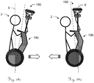
- the invention also relates to a two-wheeled, self-balancing motorized vehicle as part of a surveying system that is adapted to determine positions of a position measuring resource being mounted on the vehicle, particularly of a GNSS-antenna or of a retro-reflector.
- this vehicle is designed for transporting a user of the surveying system, in particular wherein the vehicle is designed in such a way that the user controls a forward and backward movement of the vehicle by leaning the vehicle relative to a combined centre of gravity of user and vehicle.
- this vehicle comprises measuring point marking means for marking an actual measuring point on the ground, in particular wherein the measuring point marking means comprise a laser emitting optical system for marking the measuring point with a laser spot or pattern.
- the invention also relates to a surveying subsystem comprising a camera, a profiler and a control and evaluation unit to be used as parts of a surveying system that is adapted to determine positions of a position measuring resource being mounted on a hand-carried surveying pole, particularly wherein the position measuring resource comprises a GNSS-antenna or a retro-reflector.
- the camera module is designed to be attached to the surveying pole and comprises at least one camera for capturing images.
- the profiler is designed to be attached to the surveying pole and adapted for emission of a rotating laser beam as well as for reception and detection of a returning part of the emitted laser beam being scattered back from points of a surrounding.
- the profiler is further provided with an electronic distance measuring functionality as well as an angle measuring functionality for the rotating laser beam so that profiler measurement data comprising distance and angle information is gatherable.
- the control and evaluation unit having stored a program with program code so as to control and execute a spatial representation generation functionality in which - when moving along a path through the surrounding -
- the surveying subsystem further comprises an inertial measurement unit to be attached to the surveying pole and designed for gathering IMU measurement data and the control and evaluation unit is configured so that the spatial representation generation functionality is controlled and executed in such a way, that the 6-dof-travelling-history is derived further based on the IMU measurement data, particularly wherein the IMU measurement data and the SLAM-evaluation are taken into account for deriving the rotational information of the 6-dof-travelling-history, especially wherein the IMU measurement data is used to increase resolution of rotational, and particularly also positional, information derivable from the determined poses by the SLAM-evaluation, particularly wherein - in case a Kalman filter is used for deriving the 6-dof-travelling-history - the Kalman filter is fed with the poses determined within the SLAM-evaluation, the received determined positions and the IMU measurement data.
- the camera module and the profiler each comprise a clock and a circuit for assigning a time stamp to gathered measurement data like image data, IMU measurement data and profiler measurement data, particularly wherein for the camera module and the profiler a GNSS-module is provided for gathering absolute time information from the received GNSS-signal, so that the GNSS-module is used as the clock.
- the profiler is designed in such a way that - in a condition attached to the surveying pole - the rotating laser beam defines a laser plane being
- the profiler comprises a rotatable mirror or a rotatable laser emitting and receiving unit.
- the profiler is designed in a multi-beam setup in which the profiler is adapted for emission of at least two rotating laser beams as well as for reception and detection of a returning part of each of the emitted beams being scattered back from points of a surrounding.
- the multi-beam setup is embodied with a common rotation platform for the at least two laser beams, particularly wherein the profiler is designed in a three-beam setup.
- the profiler is designed in such a way that the at least two laser beams define laser planes are parallel and slightly shifted with respect to each other, slightly inclined with respect to each other, particularly so that slightly different inclination angles with respect to the pole are formed and/or so that slightly different azimuth angles with respect to the pole are formed, or coincident with respect to each other, and/or the profiler is designed in such a way that the at least two rotating laser beams form an angular offset with respect to each other in rotation direction, particularly wherein - in case of a three-beam setup - the angular offset is 120°.
- the common rotation platform comprises a common rotatable mirror for rotatably deflecting the at least two laser beams or the common rotation platform comprises at least two laser emitting and receiving units.
- the multi-beam setup is embodied with at least two rotation platforms for the at least two laser beams.
- the profiler with the at least two rotation platforms is designed in such a way that the at least two laser beams define laser planes being inclined with respect to each other, particularly so that
- the profiler is designed in such a way that an inclination angle of a laser plane defined by the rotating laser beam is adjustable, particularly manually or motor-driven, so that - in a condition where the profiler is attached to the surveying pole - the inclination angle is variable with respect to the pole.
- the profiler is designed in such a way that an azimuth angle of a laser plane defined by the rotating laser beam is adjustable, particularly manually or motor-driven, so that - in a condition where the profiler is attached to the surveying pole - the azimuth angle is variable with respect to the pole.
- the azimuth angle is adjustable by an actuator.
- the control and evaluation unit is configured so that the spatial representation generation functionality is controlled and executed in such a way, that the azimuth angle is automatically continuously adjusted by the actuator in a manner that alterations of the azimuthal orientation of the pole - when moving along the path - are compensated for, in particular wherein the automatic continuous adjustment of the azimuth angle is based on the derived 6-dof-travelling-history or a separate evaluation using
- the actual moving direction or a smoothed moving direction is used as the moving direction, the smoothed moving direction particularly being derived for each point on the path by smoothing a most recently travelled segment of the path.
- the azimuth angle is adjusted and stabilized with respect to the surrounding by stabilisation means working according to the principle of making use of conversation of angular momentum, particularly wherein the stabilisation means comprise a flywheel, especially wherein the flywheel is rotatable together with the rotation platform which causes the laser beam to rotate.
- the invention also relates to a surveying subsystem comprising a camera module and a control and evaluation unit to be used as part of a surveying system that is adapted to determine positions of a position measuring resource being mounted on a surveying pole, particularly of a GNSS-antenna or of a retro-reflector.
- the camera module is designed to be attached to the surveying pole and comprises at least one camera for capturing images.
- the control and evaluation unit has stored a program with program code so as to control and execute a functionality in which - when moving along a path through a surrounding -
- control and evaluation unit comprises several diversified units, wherein at least a first unit, particularly an FPGA or a GPU (graphical processing unit), carries out at least part of the feature detection process for identifying the plurality of respectively corresponding image points, and at least another, second unit, particularly a CPU, carries out determining of the poses.
- a first unit particularly an FPGA or a GPU (graphical processing unit)
- a second unit particularly a CPU
- the first and second units are built together as one SoC (system on a chip).
- the first and the second unit are disposed within the camera module.
- the first unit is disposed within the camera module and the second unit is a laptop, a tablet-PC, a smartphone, a processing unit of a handheld controller/datalogger of the surveying system, a processing unit of a GNSS-module of the surveying system, a processing unit of a surveying station, particularly total station, of the surveying system or a surveying site server, particularly being installed in a car.
- the invention also relates to a surveying subsystem comprising a camera module and a control and evaluation unit to be used as part of a surveying system that is adapted to determine positions of a position measuring resource being mounted on a surveying pole, particularly of a GNSS-antenna or of a retro-reflector.
- the camera module comprises at least one camera for capturing images, wherein the camera module is built as one single integrated physical unit being designed to be attached to the surveying pole.
- the control and evaluation unit has stored a program with program code so as to control and execute a functionality in which - when moving along a path through a surrounding -
- control and evaluation unit comprises several diversified units, wherein at least one unit, being integrated in the camera module, carries out at least part of the SLAM-evaluation and at least one other unit, being disposed externally to the camera module, carries out at least parts of computing of the spatial representation.
- the at least one other unit is a cloud server.
- the at least one other unit is a laptop, a tablet-PC, a smartphone, a processing unit of a handheld controller/datalogger of the surveying system, a processing unit of a GNSS-module of the surveying system or a surveying site server, particularly being installed in a car.
- several other units being disposed externally to the camera module, carry out at least parts of computing of the spatial representation in a decentralised manner, the several other units particularly being several smartphones.
- At least one unit carrying out a part of identifying the plurality of respectively corresponding image points and/or determining the poses is designed so as to be carriable in a backpack of an operator.
- At least one unit carrying out a part of identifying the plurality of respectively corresponding image points and/or determining the poses is a laptop, a tablet-PC, a smartphone, a processing unit of a handheld controller/datalogger of the surveying system, a processing unit of a GNSS-module of the surveying system or a surveying site server, particularly being installed in a car.
- the invention also relates to a surveying subsystem comprising a camera module and a control and evaluation unit to be used as part of a surveying system that is adapted to determine positions of a position measuring resource being mounted on a hand-carried surveying pole, particularly wherein the position measuring resource comprises a GNSS-antenna or a retro-reflector.
- the camera module is designed to be attached to the surveying pole and comprises at least one camera for capturing images.
- the control and evaluation unit having stored a program with program code so as to control and execute a remote point measurement functionality in which - when moving along a path through a surrounding -
- control and evaluation unit is configured so that the remote point measurement functionality is controlled and executed in such a way, that the image point is manually selectable by a user, and/or the subset comprises all images in which the remote point appears.
- the invention also relates to a surveying subsystem comprising a camera module and a control and evaluation unit to be used as part of a surveying system that is adapted to determine positions of a position measuring resource being mounted on a hand-carried surveying pole, particularly wherein the position measuring resource comprises a GNSS-antenna or a retro-reflector.
- the camera module is designed to be attached to the surveying pole and comprises at least one camera for capturing images.
- the control and evaluation unit has stored a program with program code so as to control and execute a functionality in which - when moving along a path through a surrounding -
- control and evaluation unit is configured so that the functionality is controlled and executed in such a way, that
- control and evaluation unit is configured so that the functionality is controlled and executed in such a way, that
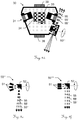
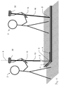
- the surveying system 1 comprises a camera module 30 and a control and evaluation unit 12.
- Figures 2a-c show camera modules 30,30' being mounted on a pole 10 together with a position measuring resource of the respective surveying system.
- Each camera module 30,30' comprises an optical recording device 31 that is sensitive to light coming from all or many spatial directions. It could be based on an imaging sensor and a fish-eye lens, or a combination of a camera and a parabolic mirror, or a minimum of two single cameras arranged on a horizontal ring, or any other optical setup functioning as a wide-angle or panorama camera.
- the camera module can be a separate module 30 which is mounted on a pole 10 together with a GNSS antenna 15 ( Figure 2a ) or a reflector 16 ( Figure 2b ). Moreover, the module 30' can be integrated into the housing of a GNSS antenna ( Figure 2c ) or reflector.
- the camera module 30' is represented by the position measuring resource which additionally comprises a GNSS antenna and/or a reflector.
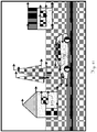
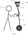
- the Figures 3a and 3b show a first embodiment of a camera module 30 according to the invention.
- the camera module 30 has a housing 40 and mounts for the pole 38 and for the position measuring resource 39 (GNSS antenna or reflector). It may comprise a set of cameras 31, e. g. four single cameras 31 aligned in angles of 90° to each other with a horizontal field-of-view >90°. In such an arrangement a horizontal field-of-view of 360° is covered.
- the vertical field-of-view (FOV) of the camera assembly can be about 60°.
- the cameras can be aligned horizontally or downward oriented, e. g. by 20°, as shown in Figure 3b . This is advantageous for applications where close objects are of particular interest.
- a processing unit 33 can be part of the camera module 30.
- the processing unit 33 can be a CPU, e. g. an ARM processor or a combination of a CPU with an FPGA, e. g. Zync SoC, or a combination of a CPU with a graphical-processing-unit (GPU).
- a combined processing unit e. g. feature tracking, etc. is carried out on the FPGA or the GPU.
- an inertial-measurement-unit (IMU) 34 can be part of the camera module.
- the IMU 34 may consist of a 3-axis accelerometer and, particularly, of a 3-axis gyroscope. Additionally, a magnetometer may be included in the IMU.
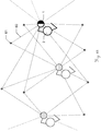
- FIGS. 4a and 4b show a second embodiment of a camera module 30 according to the invention:
- four downward-oriented cameras 31' can be combined with four upward oriented cameras 31".
- Figure 5a shows an arrangement with two fish-eye cameras 36 with a horizontal field-of-view of >180°
- Figure 5b shows an arrangement of a single camera 31 with a mirror 32, particularly a parabolic mirror, and a glass window 35.
- the cameras 31,31',31",36 of the camera modules 30 described above can have different resolutions.
- the camera module 30 comprises eight cameras, four cameras can have low resolution and are read-out in high frame rate (advantageous for feature tracking) and four cameras have high resolution (advantageous for dense matching) and are read-out with a lower frame rate.
- the high resolution cameras are not running with a specific frame rate but are triggered by the algorithm when a keyframe should be captured, e. g. in a distance interval of two meters.
- one single camera of the camera module is built so that image capturing with at least two different resolutions and/or different frame rates is provided by the camera.
- image capturing with at least two different resolutions and/or different frame rates is provided by the camera.
- a polarization filter can be mounted in front of the camera lenses (not shown here).
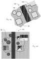
- the Figures 6a and 6b show a two further embodiments of a camera module 30 having absorber means 37,37'.
- the relative position and orientation of the cameras 31 can be determined in a calibration procedure.
- an absorber 37 can be integrated, e. g. between the housing 40 and the mount for the pole 38, as shown in Figure 6a .
- the cameras 31 and the IMU 34 can be mounted on a frame 41 which is mechnically decoupled from the housing 40 by absorbers 37,37'.
- the absorbers 37 also reduce the maximum accelerations and avoid the accellerometers to saturate.
- damping element could be in form of a gimbal mounting or the like.
- image data is recorded with the camera module 30.
- the image data is recorded in parallel, i.e. synchronously.
- the trigger signal for triggering all the single cameras can be produced by another sensor, e. g. the GNSS antenna. Alternatively, one camera can trigger all the others.
- Image data can be recorded as a video with about 15 to 25 frames per second (FPS) or as a set of event-based triggered still images, e. g. an image is recorded when the operator moved two meters since the last image was taken. Alternatively, a new image can be captured, when the image content shows a significant difference to the previous image. Moreover, the recording of an image can be triggered by the operator, when he places the pole on a point and triggers a measurement.
- FPS frames per second
- FIGS 7a-c show two further embodiments of the camera module 30.
- Each camera module 30 comprises at least two cameras 31a-d and optical triggering means 70,71 for triggering a highly synchronous capturing of images by the cameras 31a-d. This is useful for instance to allow an image stitching of the images captured by the single cameras even if the camera module is in motion.
- a ring of flash lights 70 is arranged around the camera module 30, here around the mount for the position measuring resource 39.
- the cameras 31a,31b are adapted for perceiving a light flash from the flash lights 70 in the surrounding.
- the cameras 31a,31b then can synchronously capture an image.
- synchronously captured images of the cameras 31a,31b can be identified by the means of the light flash that appears in all images that have been captured during the flash.
- the scanning units 50 integrated in the camera module 30 are advantageous for the generation of point clouds in real-time, i.e. no expensive dense matching step has to be performed as in the case of point cloud generation with images. Moreover, in contrast to camera based approaches the scanning unit 50 does not rely on good textured surfaces for the derivation of point clouds.
- the scanning unit 50 can consist of a laser emitting and receiving unit 51 and a rotation mirror 52.
- the rotating laser beam 55 is spanning a more or less horizontal plane, if the pole is aligned more or less vertically.
- FIG 8b another setup of the scanning unit 50 is shown.
- the rotation axis of the mirror is tilted by about 10° to 30° from the horizontal plane.
- Figure 8c shows the camera module 30 of Figure 8b mounted on a surveying pole 10.
- the rotating laser 55 spans a laser plane which is tilted in such a way that it passes the GNSS antenna 15, and, consequently, the occlusions are small.
- the scanning module has to be somehow exposed.
- a drop protection 18 is mounted below the camera module 30 on the pole 10.
- Figure 8d shows a combination of a camera module 30 and a separate scanning module 58. Both modules 30,58 can be plugged together. For energy supply and data transfer a connector 59 can be integrated into the housing of each module 30,58.
- the scanning module 58 can be equipped with a separate processing unit 53. Alternatively, the computations of the scanning module 58 can be carried out on the processing unit 33 of the camera module 30.
- Figure 8e shows an integrated camera module 30 with a scanning unit 50' having a rotating laser emitting and receiving unit 51' instead of a rotating mirror.
- Figure 8f shows a camera module 30 with a scanning unit 50" having a multi-beam setup with three laser emitting and receiving units 51' rotating together around one axis.
- the laser emitting and receiving unit can be mounted with an angular offset of 120°, e. g. like the blades of a wind turbine (not shown here).
- Figures 9a and 9b show an arrangement with two scanning units 50a,50b.
- the rotating beams 55a,55b of both of them span two tilted laser planes 56,56a ( Figure 9c ).
- the tilt angle influences the scanning resolution on the object, i.e. the density of the point cloud.
- an almost vertical plane scans the nearby ground in a (probably too) high resolution since the lever arm with about 2 m is quite short. Moreover, quite many rays are "wasted” since they are aimed to the sky.
- an almost horizontal plane does not cover the sky and the nearby ground at all.
- a combination of two scanning units where the rotation axis of one mirror is tilted by about 10° to 30° from the horizontal plane and the axis of the second mirror is tilted by about 10° to 30° from the vertical plane could lead to a improved distribution of the scanned points.
- the vertical angle of the laser plane can be made adjustable (this is shown in Figures 10a and 10b ). This enables the user to change the tilt angle according to his specific needs.
- the rotation can be continuous or there can be some predefined angles for high, medium and low. In the latter the scanning module clicks into the predefined positions.
- two scanning units 50a,50b which span almost vertical planes can be applied in such a way that there is a small horizontal angular offset of about 5 degrees.
- FIG. 9d -f An alternative embodiment is depicted in Figures 9d -f:
- the scanning unit 50''' comprises a plurality of laser emitting and receiving units 51.
- a fan of either diverging ( Figure 9e ) or parallel ( Figure 9f ) laser planes is generated.
- the scanning unit 50''''' can be integrated into the camera module 30 in such a way, that an unintended rotation of the pole can be compensated by a rotation of the scanning unit 50''''' into the opposite direction, in particular actuated by a drive 57.
- the rotation angle can be derived from measurements with the camera module 30, e. g. the angular rates from the IMU 34.
- the aim of the compensation can be that the azimuth of the laser plane is constant independently from the movements of the user.
- the scanning plane can automatically be aligned orthogonally to the walking direction of the user.
- the direction can for instance be derived from the state vector of the Kalman filter.
- the stabilization of the laser plane i.e. to keep the azimuth angle almost constant (smooth quick movements)
- a flying wheel 52" rotates together with the mirror around the axis to be stabilized.
- FIG 11 a rotation of the camera to the left is illustrated with a moving object in the image.
- masking of different areas can be applied in order to remove undesired (here: moving) objects.
- This for instance include static objects relative to the pole like the surveyor itself as well as moving objects like pedestrians, cars and other non-static/relative static objects.
- the masking can be done semi-automatically with user interaction or fully automatically.
- a possible scenario for user interaction guided processing is the exclusion of the surveyor in tracking feature points on the images, where the user, for instance, roughly masks the outline of itself on the image and its silhouette is recognized and subsequently tracked by an appropriate algorithm (e. g. standard segmentation algorithms, active contours or template matching).
- a fully automated algorithm might detect interfering objects based on some motion estimation algorithms, e. g. optical flow, and reject the corresponding tracked features. For instance, as is shown in figure 11 , a rotation of the camera to the left would result in an optical flow indicated by the displayed arrows 111. Although becoming more complex by more advanced movements of the camera, this vector field (optical flow) can be used to determine moving objects - indicated by the displayed arrows 112 - within the image (e. g. by analyzing discontinuities or anomalies like inconsistent local changes) or even support segmentation or other image processing related algorithms.
- some motion estimation algorithms e. g. optical flow
- Possible variants of different procedures might include interfering object detection independently on each image, initial detection and tracking, as well as global motion elimination. Additionally, in order to become more robust, the final algorithm for removing moving objects (or corresponding inconsistent feature points) might consist of a multi-step procedure, e. g. local and global motion estimation. Since global motion in this context refers to camera movement, there might also be some additional sensor information (e. g. GNSS or IMU data) used, to predict global movement and, subsequently, to stabilize the detection of moving objects.
- additional sensor information e. g. GNSS or IMU data
- the detection of corresponding (interfering) features can be carried out on the processing unit in the camera module. Particularly, if an FPGA is included in the processing unit parts of the feature detection can be computed very efficiently on the FPGA.
- the poses of the images i.e. position and orientation
- This can be done for every image with a sufficiently large number of detected point features.
- processing power can be saved by selecting a subset of images and determine the pose only for those selected images.
- a criterion for the image selection can be the baseline, i.e. the distance between the current image and the previous one, e. g. a distance of one meter. Small baselines result in a bad accuracy of 3D points determined by forward intersection.
- Another criterion can be the image quality, i.e. only image with good quality (high sharpness, no under- or over-exposure, etc.) are selected.
- the image selection can be based on a combination of image data, IMU data and GNSS data or any subset of these data sources.
- the IMU could be used to select images that don't suffer from motion blur by considering the movement and especially the rotation during exposure. This has the advantage that blur-free images are selected even when the image content changes significantly.
- Different filters e. g. baseline and motion blur
- the low resolution cameras are mainly used for feature tracking in a high frame rate.
- images can be taken with varying exposure times, e. g. the images are taken with exposure times of 1 ms, 2 ms, 4 ms, 8 ms, 10 ms, 20 ms and so on.
- the image acquisition interval can be regular, i.e. an image in an interval of 8 ms.
- the image capture interval can be irregular.
- a HDR (high dynamic range) image can be generated based on a set of images captured with different exposure times. This can be done when the camera is held sufficiently still, which can be sensed with the IMU or GNSS or camera data or a combination of all. Alternatively, the camera can be moved and the offset determined with the structure-from-motion algorithm is considered in the generation of the HDR image.
- This feedback may include light indication (e. g. status LEDs), audio signals or force feedback (vibrating pole, smartwatches, vibration wristlet, smartphone, tablet, etc.).
- light indication e. g. status LEDs
- force feedback vibrating pole, smartwatches, vibration wristlet, smartphone, tablet, etc.
- directly visualize the current state of data recording e.g. on a mobile phone, tablet or special glasses (interactive glasses).
- SLAM simultaneous localization and mapping
- the determination of the 6-DoF is based on measurements from the camera and optionally additionally position measurements from the GNSS system (and/or total station with retro-reflector). Moreover, accelerations and angular rates measured with the IMU can also be included into the determination of the poses (i.e. position and orientation with 6 degree of freedom; i.e. 6-dof).
- the image data is analyzed for corresponding features (or corresponding/homologue image points), i.e. the position of the corresponding images of one identical object point 61 in several images. This is done using feature detection and matching algorithms such as SIFT, SURF, BRISK, BRIEF, etc.
- feature detection and matching algorithms such as SIFT, SURF, BRISK, BRIEF, etc.
- object points 61 are determined. These object points build up a reference point field, which can be used for each additionally gathered camera image as a reference, so that in each newly added image existing points of the reference point filed can be used to reference the image with respect to all previous images.
- corresponding image points in this added image and already previously existing images are found/identified for new object points of the surrounding.
- these found/identified corresponding image points in the newly added image and at least one "old" image i.e. the positions of the corresponding image points in the newly added image and the old image are used to determine coordinates of further object points by forward intersection, so that the reference point field is expanded therewith by the further object points.
- the pose can be determined (based on resection using existing feature/image point schemes of existing object points of the already existing reference point field) and, on the other hand (logically simultaneously), with each newly added image the reference point field is also growing (based on forward intersection using newly identified corresponding features/image points of previously unknown object points of the surrounding).
- the correspondences i.e. the corresponding or homologue image points or features
- a tracking algorithm on each video frame, e.g. by applying the Kanade-Lucas-Tomasi (KLT) feature tracker.
- KLT Kanade-Lucas-Tomasi
- the term of "capturing a series of images with one or more cameras” includes generating image data by consecutively (e.g. following a defined timing, like one image per second, or following a defined spacing, like one image every half meter of movement) capturing/taking single images or by capturing a video frame.
- reference point field which is a point cloud with comparatively low density (therefore also often called “sparse point cloud”)
- This reference point field is at first instance only computed so as to determine the poses of the images (i.e. so as to determine and reference the positions and orientations of the image-pickups relative to each other), i.e. at least initially only for localisation purposes.
- the reference point field thus, is a consecutively growing common reference frame for determining the poses.
- the reference point field usually does not comprise pre-known points of the surrounding.
- a relative pose algorithm is used to calculate the relative pose between two selected initial frames/images and an initial point cloud (i.e. a first part of the reference point field).
- IMU and/or GNSS data can be used additionally to determine the relative pose of the selected initial frames (so as to make the step of determining the poses more stable and/or more efficient).
- the pose of the third image can be computed by resection.
- forward intersection is applied to refine the 3D coordinates of the features detected in all three images and to determine new 3D points which are detected in one of the first images and the third one. Consequently, with added image new 3D points might be reconstructed and the number of points in the point cloud (reference point field) is growing ( fig. 13 ).
- a SLAM-evaluation with a defined algorithm using the series of images is performed, wherein a plurality of respectively corresponding image points are identified in each of several sub-groups of images of the series of images and, based on resection and forward intersection using the plurality of respectively corresponding image points,
- the overall solution i.e. the built up reference point field (i.e. the derived coordinates of the reference points) and the determined poses, and optionally also the determined image-positions of the corresponding image points in the images
- This algorithm is a non-linear least squares minimization of the re-projection error and optionally also the GNSS measurements. It will optimize the location and orientation of all camera poses and all 3D points of the reference point field in one step.
- Bundle-adjustment can be triggered by the user when he is using the pole to measure individual points, i.e. in traditional GNSS pole mode. Bundle-adjustment is then used to refine the location and orientation of the pole during the measurement to provide the user with an optimal estimate for the position of the tip during the measurement.
- image data, IMU data and/or GNSS data can be used to detect if the pole is held steady in one position. Bundle-adjustment is then triggered automatically. When an optimal - bundle-adjusted - result is available this is indicated to the user through e.g. a green light. The user can then immediately read out an optimal estimate for the position of the tip upon triggering a measurement.
- the position can be used in the resection of a new camera pose or in the computation of the relative pose the initial image pair.
- the detected feature positions in the image and the GNSS position are combined in the resection algorithm.
- the accuracies of the measurements e.g. 1 px for the feature measurements and 3 cm for GNSS positions, are considered and the measurements are weighted accordingly.
- GNSS geo-referenced and scaled point cloud
- GNSS delivers positions with good accuracy on a global scale
- the positions counteract the error accumulation and the resulting drift which might appear in SLAM based on image measurements only.
- the resection also works if no GNSS signal is available by image data only. This might be the case when the operator stands very close to a façade and most GNSS satellites are covered by the building.
- the 6-DoF are then derived by resection of the camera pose based on the existing point cloud.
- the derived position can be feed back to the GNSS module for a fast reacquisition of the fix for the GNSS position.
- the pose of the module can be determined also when the line-of-sight between total station and reflector is interrupted.
- the offset between the antenna centre and the camera module has to be considered.
- This offset might be known from the mechanical design or derived by calibration. When multiple cameras are used, their relative poses have to be calibrated or derived from the design as well. Calibration can be done by the manufacturer or by the user in a specially designed procedure using e.g. a well textured area (reference pattern) being capturable be the camera to be calibrated. A defined relative spatial relationship between the pattern and the camera is pre-known. The calibration can also be fine-tuned in the bundle adjustment (self-calibration).
- the data from the inertial measurement unit i.e. accelerations and angular rates
- IMU inertial measurement unit
- the accelerometer senses the gravity vector
- the tilt of the camera module i.e. the roll and pitch angle
- the horizontal orientation of the pole i.e. the yaw angle
- a magnetometer could be used to determine the yaw angle.
- the combination of the sensor data can be carried out by a sensor fusion algorithm, e. g. a Kalman filter, a particle filter etc.
- a sensor fusion algorithm e. g. a Kalman filter, a particle filter etc.
- the coordinates of the tip point can be derived. In practical surveying this has the advantage that the operator does not have to level the pole anymore after he places the tip point onto the measuring point. Because of the reduced time needed for measuring a single point, this has a positive impact on the productivity of the operator performing the measurement job.
- Dense matching has the goal to determine a dense point cloud, i.e. a 3D-coordinate for each pixel or a subset, e.g. on a regular 3 ⁇ 3 grid, i.e. for every 3rd pixel in row and column direction, in the original images.
- the algorithm consists of two major steps.
- a disparity map is computed. This map contains the offset of a pixel in two images, i.e. the shift to be applied to a pixel in the first image to end up at the position of the corresponding point in the second image.
- correlation techniques e. g. Semi-Global-Matching, etc.
- a confidence value can be obtained and used in the further processing, e. g. for adaptive weighting of the measurements.
- 3D points are computed by forward intersection. Knowing the pose of the image rays 60 from the projection centers through the corresponding pixels are set up. The 3D coordinates of the object point results from the intersection of these rays. In principle a minimum of two rays is needed for the intersection of a 3D point. However, in practice as many rays as available are used in the forward intersection.
- Identifying the image points (reference points) and determining poses for images based on the identified image points (particularly computing a point cloud based thereon) is a be understood as a form or at least part of a dense matching process.
- the 3D coordinates of the points are determined by minimizing the deviations - actually the squared deviations - between the point and all the rays.
- the quality of the intersection can be derived by computing the variance-covariance matrix and, furthermore, an estimate for the standard deviation of all three coordinates of the 3D point.
- a quality indicative output concerning the quality of at least one of the computed points of the point cloud as described above may be based on such computation.
- the final point cloud can be filtered using several criteria on the measurement quality. This includes the number of images where the point is observed, i.e. the number of rays used for the intersection, the baseline between the cameras which defines the geometry of the intersection, a measure for the consistency of all the measurements, etc.
- a quality indicator can also be computed for an actually travelled path and actually acquired series of imaged (and also for a planned path with a planned capturing of images) solely base on pre-known circumstances like intrinsic factors (camera resolution, etc.) and general extrinsic factors (distance to camera, etc).
- a computation for the position of at least one point (and a consideration of a degree of intersection of the rays within the forward intersection) would not be necessary to for this estimated quality indicator.
- Figure 15b shows a visualisation of accuracy bounds (i.e. an accuracy map) based on an estimated reachable quality for the determination of 3d-positions in these regions. Points lying close to the planned or travelled trajectory have a higher estimated accuracy/quality and points of the surrounding lying farther from the planned or travelled trajectory have a lower estimated accuracy/quality.
- the operator places the tip point of the pole on the measuring point.
- the measurement of a dense point cloud is dynamic, i.e. the operator just walks around collecting data, i.e. image data, position data from GNSS or a total station, IMU data, etc.
- the user simply walks through the area to be mapped.
- the system records the image data, e.g. 15 frames per second, the GNSS positions and the IMU data.
- the sensors are either synchronized, e.g. triggered by a master sensor, or a time stamp is assigned to each measurement.
- a further inventive aspect is to de-blur images of the acquired series of images after computing "SLAM” (or as also called “Structure from Motion SfM”).
- a 3d-trajectory for the camera can be derived for the path travelled during acquisition of the series of images.
- a sparse point cloud for the scene/surrounding i.e. the positions of the reference point field for the surrounding extracted and used to derive the poses for the images
- SLAM algorithm is also already determined from the SLAM algorithm.
- a motion de-blurring can be performed in the images by image processing.
- imaged objects having been closer to the camera during acquisition of the image are applied with a comparatively higher degree/stage of motion de-blurring and imaged objects having been farther from the camera during acquisition of the image are applied with a comparatively lower degree/stage of motion de-blurring.
- de-blurred images After de-blurring of images of the acquired series of images, the newly generated imaged by de-blurring, which can be referred to as de-blurred images, can then substitute/replace the corresponding un-de-blurred images of the series of images.
- these de-blurred images can then constitute the series of images (i.e. then comprising only de-blurred images).
- the series of images can then consist of de-blurred images and un-de-blurred images.
- these newly or refreshed series of images then containing at least also some de-blurred images (or only de-blurred images) can be used for several purposes:
- SfM-/SLAM-evaluation on de-blurred images can provide for better results regarding the determination of the poses and the sparse point cloud, as features will be located with higher precision (and more features may be located) due to the higher contrast in the images. If the SfM is more precise, then further steps will provide better quality (dense reconstruction, meshing). But also without a refreshed SfM-/SLAM-evaluation in prefix, the dense reconstruction can be performed with at least somewhat higher quality by using the de-blurred images compared to the scenario of using un-de-blurred images.
- FIG. 16a and 16b an exemplary embodiment of a matching of two orthophotos is illustrated, wherein one orthophoto 160 is generated by the surveying system according to the invention and one is a reference orthophoto 165, for instance an aerial image.
- the term orthophoto here is understood as meaning a "true" orthophoto having an orthographic view, i.e. relief and tilt have been adjusted in order to orthorectify the image.
- the ground plane will be visible. Together with a known distance to the ground, camera locations and orientations, the images can be projected to the ground plane. By using many images from different directions, one large composite image of the ground plane can be computed. Due to the texture foreshortening (perspective effect, when cameras are looking at a certain angle to the ground), the method described in the paper "Analysis-by-Synthesis Texture Reconstruction" (Liefers, Parys, Schilling, 2012) can be used to obtain a high quality texture for the ground plane. The generated orthophoto can be registered to a georeferenced aerial image in order to localize the measurements in the geographic coordinate system. In the following paragraphs, the workflow is described in detail.
- the processing of the camera poses and the dense matching, i.e. the generation of the dense point cloud can be carried out on the processing unit as part of the camera module.
- the processing can be carried out on a controller (data logger) or the processing unit of the GNSS antenna which are connected to the camera module, either by a cable or via radio, Bluetooth, WiFi, etc.
- the data can be transmitted to a dedicated cloud server which is connected to the internet.
- the data can be transmitted directly from the camera module or via the controller or via the GNSS antenna.
- the server can be installed in a vehicle, e. g. a car which is located close to the surveying area and communicate with the pole through a local telecommunications protocol such as Bluetooth or WiFi.
- a vehicle e. g. a car which is located close to the surveying area and communicate with the pole through a local telecommunications protocol such as Bluetooth or WiFi.
- the server can be temporarily or permanently installed on site e. g. in a construction shed and com-municate with the pole through a local telecommunications protocol.
- the transmission of the data and the processing on the cloud server starts immediately after the recording is started.
- the processing is carried out in parallel to the data acquisition in the background which helps to keep the latency of the result short.
- the system can include a second processing unit which is together with a power supply, e. g. batteries, carried by the operator in a backpack.
- the second processing unit may be equipped with a graphical processing unit (GPU) which enables massive parallel processing of the image data.
- the second processing unit can be a standard portable device such as a powerful laptop, tablet computer or smartphone.
- the second processing unit may communicate with the pole through cable or a local telecommunications protocol.
- a combination of processing on the processing unit of the camera module, the processing unit of the controller or the GNSS antenna and external processing units such as a cloud server can be carried out on the processing unit included in the camera module.
- a pre-processing of the image data e. g. the feature extraction or some basic image processing algorithms, can be carried out on this processing unit.
- the SLAM algorithm which results in the poses of the images and the coordinates of a sparse point cloud can be performed on the processing unit of the controller.
- the resulting camera poses and the images can then be transmitted to a cloud server where the dense matching is performed.
- the operator should receive already in the field a preview model shortly, e. g. a few minutes, after the data acquisition is finished. Based on this preview model the operator can decide whether he captured the measuring areas completely or whether some parts are uncovered. In the latter case the operator can take some additional measurements in the uncovered area to increase the level of completeness.
- the completeness check can be augmented with contrast analysis of the images in order to detect areas that are missing and for which it is unlikely that they will be reconstructed (uniform surfaces). This would save time of the user trying to reconstruct this kind of areas.
- the decision can be done by the operator on the basis of a visualization of the preview model, e. g. a 3D visualization.
- the visualization can be 2D as a map view, to present the user with a quicker and easier-to-understand view of the model compared with 3D models which are difficult to interpret and navigate for inexperienced users.
- the missing parts are high-lighted.
- the system can guide the operator to the area of missing measurements.
- the preview model should be available shortly after the data acquisition is finished.
- the preview model may have lower resolution than the final model, e. g. a point resolution on the object of 10 cm. This can be achieved by performing particularly the dense matching on images with lower resolution, e. g. after a reduction the image resolution from 1920 ⁇ 1080 pixels to 320 ⁇ 240 pixels.
- the processing is carried out on a cloud server the reduction of the image resolution is carried out before the data is transmitted.
- the image data can be compressed before they are sent to the processing server.
- the compression of image data can be carried out in a lossless way (i.e. a lossless data compression can be applied, without reducing the quality/resolution of the images) or in a lossy way (i.e., depending on the needs and circumstances of a particular situation, also a lossy data compression can be applied, including a reduction of the quality/resolution of the images).
- the data can be reduced (areas of very low contrast do not need to be transmitted) using sparse image representations.
- additional location information can be derived. This can be used as the only source of geo-location or can be coupled with GNSS or prism-based terrestrial measurements in order to improve geo-location accuracy.
- the SLAM algorithm is executed on the dataset.
- the structure from motion can use partial GNSS data, however this is not required.
- the orthophoto generation algorithm is executed. This algorithm works as follows:
- This approach can be used for an interactive visualization of the camera position on the map on the local device's screen.
- the local SLAM computations may be joined and optimized for a good fitting together in order to find relations between different sub-reconstructions with SLAM.
- the method can be used to create a geo-referenced orthomap for use in other applications without the need of renting a plane or a UAV.
- Figure 16a shows an example orthophoto 160 generated from the images acquired at the ground level. As it can be seen, those areas 162 not captured from the ground level, such as building roofs or tree tops, are not present.
- Figure 16b presents an example reference orthophoto 165 from a georeferenced aerial image. Those two images have a different scale and orientation. By using matching of scale and rotation of invariant features the generated image can be transformed to match the scale and rotation of the reference aerial image (the borders of the orthophoto 160 from Figure 16a are represented by the outline 166). This transformation is then used to bring the point cloud and positions of the measurement instrument to the coordinate system of the reference image 165.
- the camera module can also be used without being combined with a GNSS system or a total station, in particular in applications where no absolute geo-referencing is needed. This is illustrated in Figure 17 .
- a 3D reconstruction without GNSS or total station might have an arbitrary scale.
- a state-of-the-art solution of this task is to use reference points with known 3D coordinates. These points are measured manually or automatically on the images. Their 3D coordinates are determined using additional measurement unit (e. g. with a total station). Alternatively, a scale bar could be used which is automatically identified in the image data.
- a user 2 could put the pole 10 onto the ground more than one time during the survey.
- the user could press a button on the pole to indicate the moment when the pole 10 is standing on the ground. Alternatively, this moment might be determined automatically based on comparison of sequentially recorded images or IMU information.
- the user could place the pole 10 on significant and marked points to be able to set the same coordinate system XYZ in the future (e. g. later in another survey).
- the height computation of the camera module 30 above the ground could be done manually or automatically in the reconstructed point cloud.
- a user selects points which belong to the ground.
- a height is extracted based on assumption that the pole 10 is oriented vertically.
- the height computation could also be performed in the meshed surface model.
- the GNSS data in combination with a panorama camera can be used to extend the standard SLAM approach in a new way.
- GNSS data can be used to select two frames recorded at roughly the same position but at different times. This happens when the user crosses his own path or takes the same path multiple times. Because a GNSS pole is held vertically under normal recording conditions, the main difference between the two frames is likely a horizontal rotation, i.e. a change in azimuth angle. Such a single rotation can be determined and compensated for efficiently using the raw images or detected feature points. After or during compensation of the azimuth change, optionally a compensation of the small change in the other two orientation angles can be performed in a similar way.
- a multitude of additional matches between the images can be found between the two frames by using a tracking algorithm such as KLT.
- the additional matches improve the connection between the two frames that are distant and time but not in position, i.e. loop closing. This stabilizes the algorithm and enhances the accuracy by further reducing drifts (also in rotation) for large datasets.
- Loop-closing - according to the invention - is based on capturing a first series of images of the surrounding with the at least one camera, the first series comprising an amount of images captured with different poses of the cameras, the poses representing respective positions and orientations of the cameras. Furthermore, an initial set of image points is identified based on the first series of images, the initial image points representing reference points 62 of an initial reference point field 65 ( fig. 14 ), wherein each reference point appears in at least two images of the series of images, and the poses for the images are determined based on resection using the initial image points.
- a second series of images of the surrounding is captured with the at least one camera, reference points of the reference point field 65 appearing in at least one of the images of the second series of images are identified, a further set of image points is identified in the images of the second series of images corresponding to the identified reference points 62 of the second series of images, and the poses for the images of the second series of images are determined based on resection using the initial set and the further set of image points.
- FIGS. 18 and 19a-d show two exemplary embodiments of a wheeled surveying system according to the invention that facilitate the surveying process for the user.
- the wheeled surveying system 180 depicted in Figure 18 comprises a pole 10 comprising the features of the pole of Figure 1 . Additionally, the pole 10 comprises wheels 181 that allow the user 2 to move the pole 10 along a path through the surrounding without having to carry the pole 10. To facilitate the pushing (or pulling) of the pole 10, it is equipped with a handle 182 (or two handles).
- two wheels 181 are attached to the pole 10 in such a way that the bottom end of the pole touches the ground if the pole is vertical (i.e. in a 90° angle relative to the ground). Even more preferably, the pole 10 keeps this upright position autonomously. For moving the pole 10 it needs to be tilted (as shown in Figure 18 ).
- the bottom end of the pole 10 can be extendable in order to touch the ground.
- the wheels 181 can be actuated by a motor, particularly an electric motor.
- This motor e. g. can either be controlled by the user 2 by a control unit on the handle 182 or can act as a support drive for the pushing (or pulling) movements of the user 2.
- the wheeled surveying system 190 depicted in Figures 19a-d comprises a two-wheeled, self-balancing motorized vehicle 195. This kind of vehicle is also widely known as "Segway personal transporter".
- the surveying system 190 comprises a pole 10 which is mounted on the vehicle 195. On the pole 10, as already described with respect to Figure 1 , a GNSS antenna 15 and a camera module 30 are provided.
- the surveying system 190 also comprises a control and evaluation unit 12.
- a motion of the vehicle 195 can be controlled by the user 2 as illustrated in Figures 19c and 19d :
- the depicted vehicle 195 is designed in such a way that the user 2 controls a forward and backward movement of the vehicle 195 by leaning the vehicle relative to a combined centre of gravity of user 2 and vehicle 195.
- the vehicle 195 can comprise measuring point marking means 192 that mark a spot on the ground as a present measuring point 5.
- this spot can be an imaginary extension of the pole 10.
- the marking can be a laser spot or pattern which lasts only for the stay at the respective position and is intended as information for the user 2 of the surveying system 190 driving the vehicle 195. In particular, this enables the user 2 to measure exactly at predefined marked positions.
- the marking can be more durable, for instance a sprayed paint marking or a dropped flag. This allows repeating the measurements at a later point of time at the same positions.
- an IMU of the vehicle 195 can be used for determining orientations of the cameras of the camera module 30 - either alternatively or additionally to an IMU of the camera module 30.
- the pole 10 can be equipped with a rain and/or sun protection, e. g. an umbrella being mounted below or around the GNSS antenna 15. This does not only facilitate the working conditions for the user 2 but also protects the camera module 30 and other features of the respective surveying system 1,180,190 and improves the image quality in case of precipitation.
- a rain and/or sun protection e. g. an umbrella being mounted below or around the GNSS antenna 15. This does not only facilitate the working conditions for the user 2 but also protects the camera module 30 and other features of the respective surveying system 1,180,190 and improves the image quality in case of precipitation.
Priority Applications (1)
| Application Number | Priority Date | Filing Date | Title |
|---|---|---|---|
| EP17191802.2A EP3333541A3 (fr) | 2014-05-05 | 2014-05-05 | Système de relevé |
Applications Claiming Priority (3)
| Application Number | Priority Date | Filing Date | Title |
|---|---|---|---|
| EP17191802.2A EP3333541A3 (fr) | 2014-05-05 | 2014-05-05 | Système de relevé |
| PCT/EP2014/059138 WO2015169338A1 (fr) | 2014-05-05 | 2014-05-05 | Système d'arpentage |
| EP14721402.7A EP3140613B1 (fr) | 2014-05-05 | 2014-05-05 | Système d'arpentage |
Related Parent Applications (3)
| Application Number | Title | Priority Date | Filing Date |
|---|---|---|---|
| PCT/EP2014/059138 Previously-Filed-Application WO2015169338A1 (fr) | 2014-05-05 | 2014-05-05 | Système d'arpentage |
| EP14721402.7A Division EP3140613B1 (fr) | 2014-05-05 | 2014-05-05 | Système d'arpentage |
| EP14721402.7A Division-Into EP3140613B1 (fr) | 2014-05-05 | 2014-05-05 | Système d'arpentage |
Publications (2)
| Publication Number | Publication Date |
|---|---|
| EP3333541A2 true EP3333541A2 (fr) | 2018-06-13 |
| EP3333541A3 EP3333541A3 (fr) | 2019-07-03 |
Family
ID=50639549
Family Applications (10)
| Application Number | Title | Priority Date | Filing Date |
|---|---|---|---|
| EP16202706.4A Active EP3196594B1 (fr) | 2014-05-05 | 2014-05-05 | Système d'arpentage |
| EP17191802.2A Pending EP3333541A3 (fr) | 2014-05-05 | 2014-05-05 | Système de relevé |
| EP16202710.6A Active EP3228986B1 (fr) | 2014-05-05 | 2014-05-05 | Système d'arpentage de terrain |
| EP16202708.0A Active EP3228984B1 (fr) | 2014-05-05 | 2014-05-05 | Système d'arpentage de terrain |
| EP16202709.8A Pending EP3228985A1 (fr) | 2014-05-05 | 2014-05-05 | Système d'arpentage de terrain |
| EP17191803.0A Pending EP3333542A1 (fr) | 2014-05-05 | 2014-05-05 | Système de relevé |
| EP16202704.9A Pending EP3228983A1 (fr) | 2014-05-05 | 2014-05-05 | Système d'arpentage de terrain |
| EP16202703.1A Pending EP3228982A1 (fr) | 2014-05-05 | 2014-05-05 | Système d'arpentage de terrain |
| EP14721402.7A Active EP3140613B1 (fr) | 2014-05-05 | 2014-05-05 | Système d'arpentage |
| EP19176410.9A Pending EP3569977A1 (fr) | 2014-05-05 | 2014-05-05 | Système de relevé |
Family Applications Before (1)
| Application Number | Title | Priority Date | Filing Date |
|---|---|---|---|
| EP16202706.4A Active EP3196594B1 (fr) | 2014-05-05 | 2014-05-05 | Système d'arpentage |
Family Applications After (8)
| Application Number | Title | Priority Date | Filing Date |
|---|---|---|---|
| EP16202710.6A Active EP3228986B1 (fr) | 2014-05-05 | 2014-05-05 | Système d'arpentage de terrain |
| EP16202708.0A Active EP3228984B1 (fr) | 2014-05-05 | 2014-05-05 | Système d'arpentage de terrain |
| EP16202709.8A Pending EP3228985A1 (fr) | 2014-05-05 | 2014-05-05 | Système d'arpentage de terrain |
| EP17191803.0A Pending EP3333542A1 (fr) | 2014-05-05 | 2014-05-05 | Système de relevé |
| EP16202704.9A Pending EP3228983A1 (fr) | 2014-05-05 | 2014-05-05 | Système d'arpentage de terrain |
| EP16202703.1A Pending EP3228982A1 (fr) | 2014-05-05 | 2014-05-05 | Système d'arpentage de terrain |
| EP14721402.7A Active EP3140613B1 (fr) | 2014-05-05 | 2014-05-05 | Système d'arpentage |
| EP19176410.9A Pending EP3569977A1 (fr) | 2014-05-05 | 2014-05-05 | Système de relevé |
Country Status (4)
| Country | Link |
|---|---|
| US (11) | US10234287B2 (fr) |
| EP (10) | EP3196594B1 (fr) |
| CN (10) | CN109945844B (fr) |
| WO (1) | WO2015169338A1 (fr) |
Families Citing this family (160)
| Publication number | Priority date | Publication date | Assignee | Title |
|---|---|---|---|---|
| JP6455877B2 (ja) * | 2014-10-08 | 2019-01-23 | 株式会社トプコン | 測量装置 |
| EP3021079B1 (fr) | 2014-11-14 | 2017-03-01 | Leica Geosystems AG | Système de relevé géodésique avec une visualisation de la liste des tâches |
| EP3021078B1 (fr) | 2014-11-14 | 2018-09-26 | Leica Geosystems AG | Système de relevé géodésique avec une caméra virtuelle |
| US10521472B2 (en) * | 2015-02-27 | 2019-12-31 | Realnetworks, Inc. | Composing media stories method and system |
| US10592914B2 (en) * | 2015-03-24 | 2020-03-17 | PlaceIQ, Inc. | Device-dwell graphs |
| EP3086283B1 (fr) * | 2015-04-21 | 2019-01-16 | Hexagon Technology Center GmbH | Fourniture d'un nuage de points à l'aide d'un instrument de surveillance et un dispositif de caméra |
| US10222932B2 (en) | 2015-07-15 | 2019-03-05 | Fyusion, Inc. | Virtual reality environment based manipulation of multilayered multi-view interactive digital media representations |
| US10242474B2 (en) | 2015-07-15 | 2019-03-26 | Fyusion, Inc. | Artificially rendering images using viewpoint interpolation and extrapolation |
| US11095869B2 (en) | 2015-09-22 | 2021-08-17 | Fyusion, Inc. | System and method for generating combined embedded multi-view interactive digital media representations |
| US11006095B2 (en) | 2015-07-15 | 2021-05-11 | Fyusion, Inc. | Drone based capture of a multi-view interactive digital media |
| JP6630515B2 (ja) * | 2015-08-25 | 2020-01-15 | 株式会社トプコン | 位置誘導装置、位置誘導方法、プログラム |
| US11783864B2 (en) | 2015-09-22 | 2023-10-10 | Fyusion, Inc. | Integration of audio into a multi-view interactive digital media representation |
| EP3165945B1 (fr) | 2015-11-03 | 2024-01-03 | Leica Geosystems AG | Appareil de mesure de surface destiné à déterminer des coordonnées 3d d'une surface |
| EP3391638A4 (fr) * | 2015-12-16 | 2019-08-14 | Martineau, Pierre R. | Procédé et appareil de commande d'imagerie rémanente |
| US20170178330A1 (en) * | 2015-12-17 | 2017-06-22 | Institute For Information Industry | System and method for interior mobile mapping |
| EP3182066B1 (fr) * | 2015-12-17 | 2018-07-04 | Leica Geosystems AG | Pôle d'arpentage |
| WO2017107075A1 (fr) * | 2015-12-22 | 2017-06-29 | SZ DJI Technology Co., Ltd. | Système, procédé et plate-forme mobile pour supporter l'imagerie par prises de vue en fourchette |
| TWI656692B (zh) * | 2015-12-31 | 2019-04-11 | 鴻海精密工業股份有限公司 | 通訊裝置 |
| WO2017130397A1 (fr) * | 2016-01-29 | 2017-08-03 | 富士通株式会社 | Dispositif d'estimation de position, procédé d'estimation de position, et programme d'estimation de position |
| US10546385B2 (en) * | 2016-02-25 | 2020-01-28 | Technion Research & Development Foundation Limited | System and method for image capture device pose estimation |
| WO2017193165A1 (fr) * | 2016-05-10 | 2017-11-16 | National Ict Australia Limited | Authentification d'un utilisateur |
| US9940721B2 (en) * | 2016-06-10 | 2018-04-10 | Hand Held Products, Inc. | Scene change detection in a dimensioner |
| AU2017294795B2 (en) | 2016-07-15 | 2019-06-13 | Fastbrick Ip Pty Ltd | Boom for material transport |
| AU2017294796B2 (en) | 2016-07-15 | 2019-05-30 | Fastbrick Ip Pty Ltd | Brick/block laying machine incorporated in a vehicle |
| US10489927B2 (en) * | 2016-07-18 | 2019-11-26 | King Abdullah University Of Science And Technology | System and method for three-dimensional image reconstruction using an absolute orientation sensor |
| US10120075B2 (en) | 2016-08-19 | 2018-11-06 | Faro Technologies, Inc. | Using a two-dimensional scanner to speed registration of three-dimensional scan data |
| US10488195B2 (en) | 2016-10-25 | 2019-11-26 | Microsoft Technology Licensing, Llc | Curated photogrammetry |
| US10458792B2 (en) * | 2016-12-15 | 2019-10-29 | Novatel Inc. | Remote survey system |
| EP3339714A1 (fr) * | 2016-12-20 | 2018-06-27 | Nokia Technologies Oy | Appareil et procédés associés de capture d'image de réalité virtuelle |
| US10563980B2 (en) * | 2016-12-23 | 2020-02-18 | Topcon Positioning Systems, Inc. | Enhanced remote surveying systems and methods |
| CN106705962B (zh) * | 2016-12-27 | 2019-05-07 | 首都师范大学 | 一种获取导航数据的方法及系统 |
| CN108268357B (zh) | 2016-12-30 | 2021-10-26 | 阿里巴巴集团控股有限公司 | 实时数据处理方法和装置 |
| US10437879B2 (en) | 2017-01-18 | 2019-10-08 | Fyusion, Inc. | Visual search using multi-view interactive digital media representations |
| JP6767279B2 (ja) | 2017-02-09 | 2020-10-14 | 株式会社トプコン | 測量システム |
| JP7355470B2 (ja) * | 2017-02-10 | 2023-10-03 | 株式会社トプコン | 測量装置、及び測量システム |
| CN106878597A (zh) * | 2017-03-06 | 2017-06-20 | 浙江大学 | 一种具有全景和特写功能的智能车载摄像机 |
| CN106932780A (zh) * | 2017-03-14 | 2017-07-07 | 北京京东尚科信息技术有限公司 | 物体定位方法、装置和系统 |
| US11032498B2 (en) * | 2017-03-17 | 2021-06-08 | The Regents Of The University Of Colorado, A Body | High speed two-dimensional imaging with an analog interface |
| CN110419209A (zh) * | 2017-03-31 | 2019-11-05 | 日本电气株式会社 | 信息处理装置、信息处理方法和信息处理程序 |
| US10200677B2 (en) * | 2017-05-22 | 2019-02-05 | Fyusion, Inc. | Inertial measurement unit progress estimation |
| US10237477B2 (en) * | 2017-05-22 | 2019-03-19 | Fyusion, Inc. | Loop closure |
| US10313651B2 (en) | 2017-05-22 | 2019-06-04 | Fyusion, Inc. | Snapshots at predefined intervals or angles |
| US10262243B2 (en) * | 2017-05-24 | 2019-04-16 | General Electric Company | Neural network point cloud generation system |
| CN108959321B (zh) * | 2017-05-25 | 2022-06-24 | 纵目科技(上海)股份有限公司 | 停车场地图构建方法、系统、移动终端及存储介质 |
| US11765323B2 (en) * | 2017-05-26 | 2023-09-19 | Calumino Pty Ltd. | Apparatus and method of location determination in a thermal imaging system |
| US10554957B2 (en) * | 2017-06-04 | 2020-02-04 | Google Llc | Learning-based matching for active stereo systems |
| US11392133B2 (en) * | 2017-06-06 | 2022-07-19 | Plusai, Inc. | Method and system for object centric stereo in autonomous driving vehicles |
| EP3415866B1 (fr) * | 2017-06-12 | 2020-06-03 | Hexagon Technology Center GmbH | Dispositif, système et procédé d'affichage d'écarts de mesure |
| US11069147B2 (en) | 2017-06-26 | 2021-07-20 | Fyusion, Inc. | Modification of multi-view interactive digital media representation |
| EP3649616A4 (fr) | 2017-07-05 | 2021-04-07 | Fastbrick IP Pty Ltd | Dispositif de suivi de position et d'orientation en temps réel |
| US10530997B2 (en) | 2017-07-13 | 2020-01-07 | Zillow Group, Inc. | Connecting and using building interior data acquired from mobile devices |
| US10375306B2 (en) | 2017-07-13 | 2019-08-06 | Zillow Group, Inc. | Capture and use of building interior data from mobile devices |
| DE102017117056A1 (de) * | 2017-07-27 | 2019-01-31 | Testo SE & Co. KGaA | Aufmaßgerät und Verfahren zur Erstellung eines 3D-Modells |
| WO2019026390A1 (fr) | 2017-08-01 | 2019-02-07 | ソニー株式会社 | Dispositif de traitement d'informations, procédé de traitement d'informations, support d'enregistrement et dispositif d'imagerie |
| CN107421754B (zh) * | 2017-08-08 | 2023-12-08 | 南京瑷卡测控技术有限公司 | 一种行人碰撞保护划线装置 |
| CN111226090B (zh) | 2017-08-17 | 2023-05-23 | 快砖知识产权私人有限公司 | 具有改进的横滚角测量的激光跟踪器 |
| CN111246976B (zh) | 2017-08-17 | 2024-03-15 | 快砖知识产权私人有限公司 | 交互系统配置 |
| GB2566523B (en) * | 2017-09-18 | 2020-02-26 | Jaguar Land Rover Ltd | System and method for vehicle convoys |
| WO2019071313A1 (fr) | 2017-10-11 | 2019-04-18 | Fastbrick Ip Pty Ltd | Machine destinée à transporter des objets et carrousel à plusieurs compartiments destiné à être utilisé avec cette dernière |
| US11709230B2 (en) * | 2017-10-12 | 2023-07-25 | John Matthews | Geodesic system and method of use |
| PT3477286T (pt) * | 2017-10-25 | 2023-04-24 | Hoffmann La Roche | Métodos e dispositivos para realizar uma medição analítica |
| RU178904U1 (ru) * | 2017-10-26 | 2018-04-23 | Иван Владимирович Чернов | Устройство определения азимута направления и местоположения |
| JP2021506052A (ja) * | 2017-12-07 | 2021-02-18 | アイフリー アシスティング コミュニケ−ション リミテッドEyeFree Assisting Communication Ltd. | コミュニケーション方法及びシステム |
| CN108318005A (zh) * | 2017-12-08 | 2018-07-24 | 上海工程技术大学 | 一种大型物体空间角度的测量装置 |
| CN108107462B (zh) * | 2017-12-12 | 2022-02-25 | 中国矿业大学 | Rtk与高速相机组合的交通标志杆姿态监测装置及方法 |
| CN108224008B (zh) * | 2017-12-22 | 2019-12-13 | 罗普特(厦门)科技集团有限公司 | 一种基于逐圈扫描广域全景成像光电转台装置 |
| US10657654B2 (en) * | 2017-12-28 | 2020-05-19 | Denso Ten Limited | Abnormality detection device and abnormality detection method |
| CN108510434B (zh) * | 2018-02-12 | 2019-08-20 | 中德(珠海)人工智能研究院有限公司 | 通过球幕相机进行三维建模的方法 |
| JP7232437B2 (ja) * | 2018-02-19 | 2023-03-03 | 国立大学法人 東京大学 | 作業車両の表示システム及び生成方法 |
| EP3543910B1 (fr) * | 2018-03-19 | 2023-05-17 | Rosemount Aerospace Limited | Détection cloud en imagerie aérienne |
| DE102018108141A1 (de) | 2018-04-06 | 2019-10-10 | Navvis Gmbh | Mobile Vorrichtung und Verfahren zum Erfassen eines Objektraums |
| US10643386B2 (en) | 2018-04-11 | 2020-05-05 | Zillow Group, Inc. | Presenting image transition sequences between viewing locations |
| KR102511533B1 (ko) * | 2018-04-24 | 2023-03-20 | 한화비전 주식회사 | 감시카메라용 렌즈어셈블리 및 이를 포함하는 감시 카메라 |
| US10592747B2 (en) | 2018-04-26 | 2020-03-17 | Fyusion, Inc. | Method and apparatus for 3-D auto tagging |
| US11656076B2 (en) * | 2018-05-15 | 2023-05-23 | Javad Gnss, Inc. | Method of calibrating a total station using a GNSS device |
| CN110545373B (zh) * | 2018-05-28 | 2021-12-28 | 中兴通讯股份有限公司 | 空间环境的感知方法及装置 |
| EP4036607A1 (fr) | 2018-07-20 | 2022-08-03 | Trimble Nantes S.A.S. | Dispositifs de positionnement portables et procédés permettant d'obtenir une position géospatiale |
| EP3598176A1 (fr) | 2018-07-20 | 2020-01-22 | Trimble Nantes S.A.S. | Procédés de positionnement géospatial et dispositifs de positionnement portables associés |
| TWI699705B (zh) * | 2018-08-06 | 2020-07-21 | 拓連科技股份有限公司 | 車輛之位置決定方法及系統,及其相關電腦程式產品 |
| EP3614299A1 (fr) * | 2018-08-21 | 2020-02-26 | Siemens Aktiengesellschaft | Procédé et dispositif de détection des objets dans des installations |
| EP3627100B1 (fr) * | 2018-09-20 | 2021-12-01 | Hexagon Technology Center GmbH | Rétroréflecteur à lentille avec un grand angle |
| WO2020069460A1 (fr) * | 2018-09-28 | 2020-04-02 | Bounce Imaging, Inc. | Appareil photographique panoramique et systèmes et procédés de traitement d'image |
| CA3058602C (fr) | 2018-10-11 | 2023-01-24 | Zillow Group, Inc. | Production automatisee d`information cartographique a partir d`images interdependantes |
| US10708507B1 (en) | 2018-10-11 | 2020-07-07 | Zillow Group, Inc. | Automated control of image acquisition via use of acquisition device sensors |
| US10809066B2 (en) | 2018-10-11 | 2020-10-20 | Zillow Group, Inc. | Automated mapping information generation from inter-connected images |
| CN108981719B (zh) * | 2018-10-12 | 2024-03-01 | 中国空气动力研究与发展中心超高速空气动力研究所 | 一种超高速飞行模型位姿变化测量装置及方法 |
| US10380440B1 (en) | 2018-10-23 | 2019-08-13 | Capital One Services, Llc | Method for determining correct scanning distance using augmented reality and machine learning models |
| US11309947B2 (en) * | 2018-11-19 | 2022-04-19 | Facebook Technologies, Llc | Systems and methods for maintaining directional wireless links of motile devices |
| SE543047C2 (en) | 2018-12-04 | 2020-09-29 | Bjorkstrom Robotics Ab | A computer-implemented method, a computer program product, and an apparatus for facilitating placement of a surveying tool |
| CN109343572B (zh) * | 2018-12-20 | 2021-07-30 | 深圳市道通智能航空技术股份有限公司 | 一种无人机自主降落方法、装置及无人机 |
| WO2020137069A1 (fr) * | 2018-12-28 | 2020-07-02 | 株式会社Nttドコモ | Système d'estimation de position |
| US10958887B2 (en) * | 2019-01-14 | 2021-03-23 | Fyusion, Inc. | Free-viewpoint photorealistic view synthesis from casually captured video |
| EP3693698A1 (fr) * | 2019-02-05 | 2020-08-12 | Leica Geosystems AG | Appareil de mesure pourvu de caméra à base d'événements |
| CN109859137B (zh) * | 2019-02-14 | 2023-02-17 | 重庆邮电大学 | 一种广角相机非规则畸变全域校正方法 |
| CN110044340B (zh) * | 2019-02-26 | 2021-06-29 | 中国一冶集团有限公司 | 半球形钢结构壳体尺寸测量控制方法 |
| US10616483B1 (en) * | 2019-02-27 | 2020-04-07 | Hong Kong Applied Science and Technology Research Institute Company Limited | Apparatus and method of generating electronic three-dimensional walkthrough environment |
| CN109947886B (zh) * | 2019-03-19 | 2023-01-10 | 腾讯科技(深圳)有限公司 | 图像处理方法、装置、电子设备及存储介质 |
| WO2020219982A1 (fr) * | 2019-04-24 | 2020-10-29 | Nextvr Inc. | Procédés et appareils pour le codage, la communication et/ou l'utilisation d'images |
| EP3734222A1 (fr) * | 2019-05-02 | 2020-11-04 | Leica Geosystems AG | Dispositif de mesure et/ou de délimitation de coordonnées |
| CN110095752B (zh) * | 2019-05-07 | 2021-08-10 | 百度在线网络技术(北京)有限公司 | 定位方法、装置、设备和介质 |
| JP7202261B2 (ja) * | 2019-06-10 | 2023-01-11 | 株式会社トプコン | 測量装置 |
| RU192273U1 (ru) * | 2019-06-13 | 2019-09-11 | Александр Александрович Федоровский | Система наземной стереосъемки |
| CN110427026B (zh) * | 2019-07-15 | 2022-09-13 | 北京天时行智能科技有限公司 | 一种轮胎道路摩擦的确定方法及装置 |
| CN110274575A (zh) * | 2019-07-17 | 2019-09-24 | 伟志股份公司 | 一种基于gps技术的路线勘测系统及方法 |
| JP2022540679A (ja) * | 2019-07-17 | 2022-09-16 | メタウェーブ コーポレーション | ワイヤレス通信環境における増強されたアンテナ配置のための走査システム |
| CN110426674B (zh) * | 2019-07-17 | 2021-12-14 | 浙江大华技术股份有限公司 | 一种空间位置确定方法、装置、电子设备及存储介质 |
| US11250606B2 (en) * | 2019-07-31 | 2022-02-15 | Grabango Co. | Privacy protection in vision systems |
| DE102019120702A1 (de) * | 2019-07-31 | 2021-02-04 | Navvis Gmbh | Gestell für zumindest eine Scaneinrichtung und Raumerfassungsvorrichtung mit zumindest einer Scaneinrichtung |
| CN110440760B (zh) * | 2019-08-14 | 2022-05-20 | 散裂中子源科学中心 | 一种高精度摄影测量目标的制备方法 |
| US11808866B2 (en) | 2019-08-16 | 2023-11-07 | Javad Gnss, Inc. | Total station with GNSS device |
| US11566896B2 (en) * | 2019-08-22 | 2023-01-31 | Leica Geosystems Ag | Surveying system with image-based measuring |
| US11243656B2 (en) | 2019-08-28 | 2022-02-08 | Zillow, Inc. | Automated tools for generating mapping information for buildings |
| EP3788933A1 (fr) * | 2019-09-05 | 2021-03-10 | BSH Hausgeräte GmbH | Procédé de commande d'un appareil domestique |
| CN110657782A (zh) * | 2019-09-20 | 2020-01-07 | 武汉大学 | 一种新型单镜头立体测绘装置及测绘方法 |
| US11164368B2 (en) | 2019-10-07 | 2021-11-02 | Zillow, Inc. | Providing simulated lighting information for three-dimensional building models |
| JP7314447B2 (ja) * | 2019-10-25 | 2023-07-26 | 株式会社トプコン | スキャナシステム及びスキャン方法 |
| DE102019216548A1 (de) * | 2019-10-28 | 2021-04-29 | DeepUp GmbH | Verfahren und mobile Erfassungsvorrichtung zur Erfassung von Infrastrukturelementen eines unterirdischen Leitungsnetzwerks |
| US11164361B2 (en) | 2019-10-28 | 2021-11-02 | Zillow, Inc. | Generating floor maps for buildings from automated analysis of visual data of the buildings' interiors |
| US10825247B1 (en) | 2019-11-12 | 2020-11-03 | Zillow Group, Inc. | Presenting integrated building information using three-dimensional building models |
| US11676344B2 (en) | 2019-11-12 | 2023-06-13 | MFTB Holdco, Inc. | Presenting building information using building models |
| US11295473B2 (en) * | 2019-12-18 | 2022-04-05 | Intel Corporation | Continuous local 3D reconstruction refinement in video |
| EP4078086A1 (fr) * | 2019-12-19 | 2022-10-26 | Trimble Inc. | Suivi de surface avec de multiples appareils de prise de vues sur un mât |
| US11536857B2 (en) | 2019-12-19 | 2022-12-27 | Trimble Inc. | Surface tracking on a survey pole |
| US11175134B2 (en) * | 2019-12-19 | 2021-11-16 | Trimble Inc. | Surface tracking with multiple cameras on a pole |
| CN113093256B (zh) * | 2019-12-23 | 2024-02-13 | 上海华测导航技术股份有限公司 | 一种gnss/imu测绘系统和方法 |
| US11816855B2 (en) * | 2020-02-11 | 2023-11-14 | Samsung Electronics Co., Ltd. | Array-based depth estimation |
| CN111693725B (zh) * | 2020-06-01 | 2022-07-15 | 中光智控(北京)科技有限公司 | 一种瞄准目标运动角速率测量方法及装置 |
| US11405549B2 (en) | 2020-06-05 | 2022-08-02 | Zillow, Inc. | Automated generation on mobile devices of panorama images for building locations and subsequent use |
| US11436804B2 (en) * | 2020-06-10 | 2022-09-06 | Arm Limited | Augmented reality system |
| US11514674B2 (en) * | 2020-09-04 | 2022-11-29 | Zillow, Inc. | Automated analysis of image contents to determine the acquisition location of the image |
| US11592969B2 (en) | 2020-10-13 | 2023-02-28 | MFTB Holdco, Inc. | Automated tools for generating building mapping information |
| US11481925B1 (en) | 2020-11-23 | 2022-10-25 | Zillow, Inc. | Automated determination of image acquisition locations in building interiors using determined room shapes |
| CN112525107B (zh) * | 2020-11-24 | 2022-09-09 | 浙江知象光电科技有限公司 | 一种基于事件相机的结构光三维测量方法 |
| CN112489176B (zh) * | 2020-11-26 | 2021-09-21 | 香港理工大学深圳研究院 | 一种融合ESKF,g2o和点云匹配的紧耦合建图方法 |
| CN112434637B (zh) * | 2020-12-04 | 2021-07-16 | 上海交通大学 | 基于量子计算线路和LiDAR点云分类的物体识别方法 |
| CN112455726B (zh) * | 2020-12-10 | 2022-04-19 | 长光卫星技术股份有限公司 | 一种低轨光学遥感卫星多点成像快速机动控制方法 |
| EP4012334B1 (fr) * | 2020-12-11 | 2023-10-18 | Leica Geosystems AG | Pôle d'arpentage et unité de capteur secondaire ayant une forme toroïdale |
| CN112747746A (zh) * | 2020-12-25 | 2021-05-04 | 珠海市一微半导体有限公司 | 基于单点tof的点云数据获取方法、芯片和移动机器人 |
| US11252329B1 (en) | 2021-01-08 | 2022-02-15 | Zillow, Inc. | Automated determination of image acquisition locations in building interiors using multiple data capture devices |
| CA3142154A1 (fr) | 2021-01-08 | 2022-07-08 | Zillow, Inc. | Determination automatisee d'emplacements d'acquisition d'images dans les lieux interieurs de batiment au moyen de multiples dispositifs d'enregistrement de donnees |
| CN112819943B (zh) * | 2021-01-15 | 2022-08-30 | 北京航空航天大学 | 一种基于全景相机的主动视觉slam系统 |
| US11790648B2 (en) | 2021-02-25 | 2023-10-17 | MFTB Holdco, Inc. | Automated usability assessment of buildings using visual data of captured in-room images |
| US11836973B2 (en) | 2021-02-25 | 2023-12-05 | MFTB Holdco, Inc. | Automated direction of capturing in-room information for use in usability assessment of buildings |
| CN112995484B (zh) * | 2021-03-17 | 2022-09-16 | 烟台业达智慧城市运营科技有限公司 | 一种基于人工智能的监控摄像头 |
| US11908198B2 (en) * | 2021-03-18 | 2024-02-20 | Pony Ai Inc. | Contextualization and refinement of simultaneous localization and mapping |
| EP4323969A2 (fr) * | 2021-04-16 | 2024-02-21 | Hover Inc. | Systèmes et procédés pour générer ou effectuer le rendu d'une représentation tridimensionnelle |
| TWI772020B (zh) * | 2021-05-12 | 2022-07-21 | 廣達電腦股份有限公司 | 影像定位裝置和方法 |
| EP4092379A1 (fr) * | 2021-05-20 | 2022-11-23 | Hexagon Technology Center GmbH | Dispositif de surveillance doté d'un évaluateur d'image permettant de déterminer une pose spatiale de l'axe cible |
| CN113552596A (zh) * | 2021-07-22 | 2021-10-26 | 中国十七冶集团有限公司 | 一种基于云边结合的新型gnss测量系统及测量方法 |
| US11501492B1 (en) | 2021-07-27 | 2022-11-15 | Zillow, Inc. | Automated room shape determination using visual data of multiple captured in-room images |
| CN113820735B (zh) * | 2021-08-31 | 2023-12-01 | 上海华测导航技术股份有限公司 | 位置信息的确定方法、位置测量设备、终端及存储介质 |
| US11842464B2 (en) | 2021-09-22 | 2023-12-12 | MFTB Holdco, Inc. | Automated exchange and use of attribute information between building images of multiple types |
| CN113847907A (zh) * | 2021-09-29 | 2021-12-28 | 深圳市慧鲤科技有限公司 | 定位方法及装置、设备、存储介质 |
| CN113933876B (zh) * | 2021-11-16 | 2023-05-23 | 西南电子技术研究所(中国电子科技集团公司第十研究所) | 多星通讯时差定位数据融合处理方法 |
| DE102021131129A1 (de) | 2021-11-26 | 2023-06-01 | Navvis Gmbh | Mobile vorrichtung und verfahren zum erfassen eines objektraums |
| CN114003045B (zh) * | 2021-12-30 | 2022-04-15 | 成都星宇融科电力电子股份有限公司 | 一种光电跟踪仪的目标跟踪方法、终端、可读存储介质 |
| AU2022200797A1 (en) * | 2022-02-04 | 2023-08-24 | Kelvin Chin Yeoh Lim | All seeing eyes housing system |
| CN114910933B (zh) * | 2022-03-10 | 2024-03-19 | 苏州天硕导航科技有限责任公司 | 带视觉测量功能的rtk接收机系统、板卡及测量方法 |
| US11830135B1 (en) | 2022-07-13 | 2023-11-28 | MFTB Holdco, Inc. | Automated building identification using floor plans and acquired building images |
| CN115829963B (zh) * | 2022-11-28 | 2023-11-03 | 江苏凯威特斯半导体科技有限公司 | 一种等离子喷涂图像数据识别分析方法和系统 |
Family Cites Families (32)
| Publication number | Priority date | Publication date | Assignee | Title |
|---|---|---|---|---|
| US5988862A (en) * | 1996-04-24 | 1999-11-23 | Cyra Technologies, Inc. | Integrated system for quickly and accurately imaging and modeling three dimensional objects |
| WO2000060853A1 (fr) * | 1999-04-08 | 2000-10-12 | Internet Pictures Corporation | Procede et dispositif servant a produire des effets de traitement virtuels pour des images video grand angle |
| US20060012777A1 (en) | 2004-07-13 | 2006-01-19 | Talbot Nicholas C | Combination laser system and global navigation satellite system |
| US20060028550A1 (en) * | 2004-08-06 | 2006-02-09 | Palmer Robert G Jr | Surveillance system and method |
| US8415523B2 (en) * | 2005-04-16 | 2013-04-09 | Aalnex, Inc. | Secondary wound dressings for securing primary dressings and managing fluid from wounds, and methods of using same |
| US7541974B2 (en) | 2005-12-15 | 2009-06-02 | Trimble Navigation Limited | Managed traverse system and method to acquire accurate survey data in absence of precise GPS data |
| US8942483B2 (en) | 2009-09-14 | 2015-01-27 | Trimble Navigation Limited | Image-based georeferencing |
| JP5057734B2 (ja) | 2006-09-25 | 2012-10-24 | 株式会社トプコン | 測量方法及び測量システム及び測量データ処理プログラム |
| ES2327999B1 (es) * | 2007-08-06 | 2010-08-30 | Archidab Urban Media, S.L. | Procedimiento, programa de ordenador y archivo para generar imagenes que reproducen un entorno tridimensional real. |
| AU2014200772B2 (en) * | 2008-02-13 | 2015-12-17 | Caterpillar Inc. | Terrain map updating system |
| US8351684B2 (en) | 2008-02-13 | 2013-01-08 | Caterpillar Inc. | Terrain map updating system |
| DE112010000812T5 (de) | 2009-01-08 | 2012-06-06 | Trimble Navigation Limited | Verfahren und Systeme zum Bestimmen von Winkeln und Orten von Punkten |
| CN101487703B (zh) * | 2009-02-13 | 2011-11-23 | 浙江工业大学 | 快速全景立体摄像测量装置 |
| CN101561270B (zh) * | 2009-05-27 | 2011-05-04 | 天津理工大学 | 嵌入式全向球视觉目标检测和移动监控系统及方法 |
| US9879992B2 (en) | 2009-12-29 | 2018-01-30 | Trimble Inc. | Virtual perspective center aligned with measurement center |
| JP6002126B2 (ja) * | 2010-06-25 | 2016-10-05 | トリンブル ナビゲーション リミテッドTrimble Navigation Limited | 画像ベースの測位のための方法および装置 |
| CN102486376A (zh) * | 2010-12-04 | 2012-06-06 | 鸿富锦精密工业(深圳)有限公司 | 影像差异部位标注系统及方法 |
| CN102080969B (zh) | 2010-12-16 | 2012-07-11 | 哈尔滨工程大学 | 全景视觉测量系统安装位置快速校正装置 |
| EP2511781A1 (fr) * | 2011-04-14 | 2012-10-17 | Hexagon Technology Center GmbH | Système et procédé de commande d'un aéronef sans pilote |
| US9758239B2 (en) | 2011-04-14 | 2017-09-12 | Hexagon Technology Center Gmbh | System and method for controlling an unmanned air vehicle |
| US9109889B2 (en) * | 2011-06-24 | 2015-08-18 | Trimble Navigation Limited | Determining tilt angle and tilt direction using image processing |
| US9134127B2 (en) | 2011-06-24 | 2015-09-15 | Trimble Navigation Limited | Determining tilt angle and tilt direction using image processing |
| CN103438868B (zh) * | 2012-01-09 | 2015-09-09 | 刘进 | 基于球面全景相机的物体高度测量方法 |
| US9513120B2 (en) | 2012-09-20 | 2016-12-06 | Trimble Navigation Limited | Workflow improvements for stakeout |
| CN103017739B (zh) * | 2012-11-20 | 2015-04-29 | 武汉大学 | 基于激光雷达点云与航空影像的真正射影像的制作方法 |
| US9083960B2 (en) | 2013-01-30 | 2015-07-14 | Qualcomm Incorporated | Real-time 3D reconstruction with power efficient depth sensor usage |
| US9247239B2 (en) | 2013-06-20 | 2016-01-26 | Trimble Navigation Limited | Use of overlap areas to optimize bundle adjustment |
| EP2829842B1 (fr) * | 2013-07-22 | 2022-12-21 | Hexagon Technology Center GmbH | Procédé, système et produit programme d'ordinateur pour déterminer un volume absolu d'un stock à l'aide d'un algorithme d'acquisition de structure à partir d'un mouvement |
| CN103411587B (zh) * | 2013-08-14 | 2015-08-19 | 史云 | 定位定姿方法及系统 |
| US20150092048A1 (en) * | 2013-09-27 | 2015-04-02 | Qualcomm Incorporated | Off-Target Tracking Using Feature Aiding in the Context of Inertial Navigation |
| CN103644897B (zh) * | 2013-12-17 | 2016-01-13 | 中国科学院遥感与数字地球研究所 | 一种基于超分辨率影像重建的三维量测方法 |
| JP6062079B2 (ja) | 2014-05-30 | 2017-01-18 | エスゼット ディージェイアイ テクノロジー カンパニー リミテッドSz Dji Technology Co.,Ltd | 無人型航空輸送機(uav)の動作を制御するための制御器および方法ならびに乗り物 |
-
2014
- 2014-05-05 CN CN201811582495.8A patent/CN109945844B/zh active Active
- 2014-05-05 EP EP16202706.4A patent/EP3196594B1/fr active Active
- 2014-05-05 CN CN201710846461.4A patent/CN107655461B/zh active Active
- 2014-05-05 EP EP17191802.2A patent/EP3333541A3/fr active Pending
- 2014-05-05 WO PCT/EP2014/059138 patent/WO2015169338A1/fr active Application Filing
- 2014-05-05 CN CN201710846198.9A patent/CN107727076B/zh active Active
- 2014-05-05 EP EP16202710.6A patent/EP3228986B1/fr active Active
- 2014-05-05 CN CN201611120371.9A patent/CN106959103B/zh active Active
- 2014-05-05 EP EP16202708.0A patent/EP3228984B1/fr active Active
- 2014-05-05 EP EP16202709.8A patent/EP3228985A1/fr active Pending
- 2014-05-05 EP EP17191803.0A patent/EP3333542A1/fr active Pending
- 2014-05-05 CN CN201611120364.9A patent/CN106908046B/zh active Active
- 2014-05-05 CN CN201611120367.2A patent/CN107084710B/zh active Active
- 2014-05-05 CN CN201480078610.1A patent/CN106461391B/zh active Active
- 2014-05-05 EP EP16202704.9A patent/EP3228983A1/fr active Pending
- 2014-05-05 CN CN201611120164.3A patent/CN106959102B/zh active Active
- 2014-05-05 CN CN201611120366.8A patent/CN107101620B/zh active Active
- 2014-05-05 EP EP16202703.1A patent/EP3228982A1/fr active Pending
- 2014-05-05 EP EP14721402.7A patent/EP3140613B1/fr active Active
- 2014-05-05 US US15/308,827 patent/US10234287B2/en active Active
- 2014-05-05 EP EP19176410.9A patent/EP3569977A1/fr active Pending
- 2014-05-05 CN CN201611120368.7A patent/CN106918331B/zh active Active
-
2016
- 2016-12-05 US US15/369,581 patent/US10359283B2/en active Active
- 2016-12-08 US US15/373,280 patent/US10274316B2/en active Active
- 2016-12-08 US US15/373,226 patent/US10655962B2/en active Active
-
2017
- 2017-09-28 US US15/719,368 patent/US10281276B2/en active Active
-
2018
- 2018-11-20 US US16/197,071 patent/US10371518B2/en active Active
-
2019
- 2019-01-22 US US16/253,522 patent/US10605601B2/en active Active
- 2019-04-17 US US16/387,398 patent/US10605602B2/en active Active
- 2019-04-26 US US16/396,528 patent/US10488198B2/en active Active
- 2019-04-29 US US16/398,101 patent/US10495461B2/en active Active
-
2020
- 2020-04-13 US US16/847,240 patent/US11054258B2/en active Active
Also Published As
Similar Documents
| Publication | Publication Date | Title |
|---|---|---|
| US11054258B2 (en) | Surveying system |
Legal Events
| Date | Code | Title | Description |
|---|---|---|---|
| PUAI | Public reference made under article 153(3) epc to a published international application that has entered the european phase |
Free format text: ORIGINAL CODE: 0009012 |
|
| STAA | Information on the status of an ep patent application or granted ep patent |
Free format text: STATUS: THE APPLICATION HAS BEEN PUBLISHED |
|
| AC | Divisional application: reference to earlier application |
Ref document number: 3140613 Country of ref document: EP Kind code of ref document: P |
|
| AK | Designated contracting states |
Kind code of ref document: A2 Designated state(s): AL AT BE BG CH CY CZ DE DK EE ES FI FR GB GR HR HU IE IS IT LI LT LU LV MC MK MT NL NO PL PT RO RS SE SI SK SM TR |
|
| RIN1 | Information on inventor provided before grant (corrected) |
Inventor name: FIDLER, THOMAS Inventor name: PARYS, ROMAN Inventor name: SIERCKS, KNUT Inventor name: VELIZHEV, ALEXANDER Inventor name: METZLER, BERNHARD Inventor name: SCHEJA, JOCHEN Inventor name: VAN DER ZWAN, ELMAR VINCENT |
|
| PUAL | Search report despatched |
Free format text: ORIGINAL CODE: 0009013 |
|
| AK | Designated contracting states |
Kind code of ref document: A3 Designated state(s): AL AT BE BG CH CY CZ DE DK EE ES FI FR GB GR HR HU IE IS IT LI LT LU LV MC MK MT NL NO PL PT RO RS SE SI SK SM TR |
|
| RIC1 | Information provided on ipc code assigned before grant |
Ipc: G01S 19/42 20100101ALI20190524BHEP Ipc: G01C 15/00 20060101AFI20190524BHEP |
|
| RIN1 | Information on inventor provided before grant (corrected) |
Inventor name: VELIZHEV, ALEXANDER Inventor name: VAN DER ZWAN, ELMAR VINCENT Inventor name: METZLER, BERNHARD Inventor name: FIDLER, THOMAS Inventor name: SCHEJA, JOCHEN Inventor name: PARYS, ROMAN Inventor name: SIERCKS, KNUT |
|
| RIN1 | Information on inventor provided before grant (corrected) |
Inventor name: SIERCKS, KNUT Inventor name: SCHEJA, JOCHEN Inventor name: VAN DER ZWAN, ELMAR VINCENT Inventor name: VELIZHEV, ALEXANDER Inventor name: PARYS, ROMAN Inventor name: METZLER, BERNHARD Inventor name: FIDLER, THOMAS |
|
| RIN1 | Information on inventor provided before grant (corrected) |
Inventor name: SCHEJA, JOCHEN Inventor name: SIERCKS, KNUT Inventor name: METZLER, BERNHARD Inventor name: FIDLER, THOMAS Inventor name: VAN DER ZWAN, ELMAR VINCENT Inventor name: VELIZHEV, ALEXANDER Inventor name: PARYS, ROMAN |
|
| STAA | Information on the status of an ep patent application or granted ep patent |
Free format text: STATUS: REQUEST FOR EXAMINATION WAS MADE |
|
| 17P | Request for examination filed |
Effective date: 20191223 |
|
| RBV | Designated contracting states (corrected) |
Designated state(s): AL AT BE BG CH CY CZ DE DK EE ES FI FR GB GR HR HU IE IS IT LI LT LU LV MC MK MT NL NO PL PT RO RS SE SI SK SM TR |
|
| STAA | Information on the status of an ep patent application or granted ep patent |
Free format text: STATUS: EXAMINATION IS IN PROGRESS |
|
| 17Q | First examination report despatched |
Effective date: 20220509 |