EP3086283B1 - Fourniture d'un nuage de points à l'aide d'un instrument de surveillance et un dispositif de caméra - Google Patents
Fourniture d'un nuage de points à l'aide d'un instrument de surveillance et un dispositif de caméra Download PDFInfo
- Publication number
- EP3086283B1 EP3086283B1 EP15164442.4A EP15164442A EP3086283B1 EP 3086283 B1 EP3086283 B1 EP 3086283B1 EP 15164442 A EP15164442 A EP 15164442A EP 3086283 B1 EP3086283 B1 EP 3086283B1
- Authority
- EP
- European Patent Office
- Prior art keywords
- image
- images
- point cloud
- points
- scanning
- Prior art date
- Legal status (The legal status is an assumption and is not a legal conclusion. Google has not performed a legal analysis and makes no representation as to the accuracy of the status listed.)
- Active
Links
Images


Classifications
-
- G—PHYSICS
- G01—MEASURING; TESTING
- G01C—MEASURING DISTANCES, LEVELS OR BEARINGS; SURVEYING; NAVIGATION; GYROSCOPIC INSTRUMENTS; PHOTOGRAMMETRY OR VIDEOGRAMMETRY
- G01C15/00—Surveying instruments or accessories not provided for in groups G01C1/00 - G01C13/00
- G01C15/002—Active optical surveying means
-
- G—PHYSICS
- G01—MEASURING; TESTING
- G01C—MEASURING DISTANCES, LEVELS OR BEARINGS; SURVEYING; NAVIGATION; GYROSCOPIC INSTRUMENTS; PHOTOGRAMMETRY OR VIDEOGRAMMETRY
- G01C11/00—Photogrammetry or videogrammetry, e.g. stereogrammetry; Photographic surveying
- G01C11/02—Picture taking arrangements specially adapted for photogrammetry or photographic surveying, e.g. controlling overlapping of pictures
- G01C11/025—Picture taking arrangements specially adapted for photogrammetry or photographic surveying, e.g. controlling overlapping of pictures by scanning the object
-
- G—PHYSICS
- G01—MEASURING; TESTING
- G01C—MEASURING DISTANCES, LEVELS OR BEARINGS; SURVEYING; NAVIGATION; GYROSCOPIC INSTRUMENTS; PHOTOGRAMMETRY OR VIDEOGRAMMETRY
- G01C11/00—Photogrammetry or videogrammetry, e.g. stereogrammetry; Photographic surveying
- G01C11/04—Interpretation of pictures
- G01C11/06—Interpretation of pictures by comparison of two or more pictures of the same area
-
- G—PHYSICS
- G01—MEASURING; TESTING
- G01C—MEASURING DISTANCES, LEVELS OR BEARINGS; SURVEYING; NAVIGATION; GYROSCOPIC INSTRUMENTS; PHOTOGRAMMETRY OR VIDEOGRAMMETRY
- G01C3/00—Measuring distances in line of sight; Optical rangefinders
-
- G—PHYSICS
- G06—COMPUTING; CALCULATING OR COUNTING
- G06F—ELECTRIC DIGITAL DATA PROCESSING
- G06F18/00—Pattern recognition
- G06F18/20—Analysing
- G06F18/25—Fusion techniques
- G06F18/253—Fusion techniques of extracted features
-
- G—PHYSICS
- G06—COMPUTING; CALCULATING OR COUNTING
- G06T—IMAGE DATA PROCESSING OR GENERATION, IN GENERAL
- G06T7/00—Image analysis
- G06T7/30—Determination of transform parameters for the alignment of images, i.e. image registration
- G06T7/33—Determination of transform parameters for the alignment of images, i.e. image registration using feature-based methods
- G06T7/337—Determination of transform parameters for the alignment of images, i.e. image registration using feature-based methods involving reference images or patches
-
- G—PHYSICS
- G06—COMPUTING; CALCULATING OR COUNTING
- G06T—IMAGE DATA PROCESSING OR GENERATION, IN GENERAL
- G06T7/00—Image analysis
- G06T7/30—Determination of transform parameters for the alignment of images, i.e. image registration
- G06T7/38—Registration of image sequences
-
- G—PHYSICS
- G06—COMPUTING; CALCULATING OR COUNTING
- G06T—IMAGE DATA PROCESSING OR GENERATION, IN GENERAL
- G06T7/00—Image analysis
- G06T7/50—Depth or shape recovery
- G06T7/521—Depth or shape recovery from laser ranging, e.g. using interferometry; from the projection of structured light
-
- G—PHYSICS
- G06—COMPUTING; CALCULATING OR COUNTING
- G06T—IMAGE DATA PROCESSING OR GENERATION, IN GENERAL
- G06T7/00—Image analysis
- G06T7/50—Depth or shape recovery
- G06T7/55—Depth or shape recovery from multiple images
- G06T7/579—Depth or shape recovery from multiple images from motion
-
- G—PHYSICS
- G06—COMPUTING; CALCULATING OR COUNTING
- G06T—IMAGE DATA PROCESSING OR GENERATION, IN GENERAL
- G06T7/00—Image analysis
- G06T7/70—Determining position or orientation of objects or cameras
- G06T7/73—Determining position or orientation of objects or cameras using feature-based methods
-
- G—PHYSICS
- G06—COMPUTING; CALCULATING OR COUNTING
- G06V—IMAGE OR VIDEO RECOGNITION OR UNDERSTANDING
- G06V10/00—Arrangements for image or video recognition or understanding
- G06V10/70—Arrangements for image or video recognition or understanding using pattern recognition or machine learning
- G06V10/77—Processing image or video features in feature spaces; using data integration or data reduction, e.g. principal component analysis [PCA] or independent component analysis [ICA] or self-organising maps [SOM]; Blind source separation
- G06V10/80—Fusion, i.e. combining data from various sources at the sensor level, preprocessing level, feature extraction level or classification level
- G06V10/806—Fusion, i.e. combining data from various sources at the sensor level, preprocessing level, feature extraction level or classification level of extracted features
-
- H—ELECTRICITY
- H04—ELECTRIC COMMUNICATION TECHNIQUE
- H04N—PICTORIAL COMMUNICATION, e.g. TELEVISION
- H04N23/00—Cameras or camera modules comprising electronic image sensors; Control thereof
- H04N23/60—Control of cameras or camera modules
- H04N23/698—Control of cameras or camera modules for achieving an enlarged field of view, e.g. panoramic image capture
-
- G—PHYSICS
- G06—COMPUTING; CALCULATING OR COUNTING
- G06T—IMAGE DATA PROCESSING OR GENERATION, IN GENERAL
- G06T2207/00—Indexing scheme for image analysis or image enhancement
- G06T2207/10—Image acquisition modality
- G06T2207/10016—Video; Image sequence
-
- G—PHYSICS
- G06—COMPUTING; CALCULATING OR COUNTING
- G06T—IMAGE DATA PROCESSING OR GENERATION, IN GENERAL
- G06T2207/00—Indexing scheme for image analysis or image enhancement
- G06T2207/10—Image acquisition modality
- G06T2207/10024—Color image
-
- G—PHYSICS
- G06—COMPUTING; CALCULATING OR COUNTING
- G06T—IMAGE DATA PROCESSING OR GENERATION, IN GENERAL
- G06T2207/00—Indexing scheme for image analysis or image enhancement
- G06T2207/10—Image acquisition modality
- G06T2207/10028—Range image; Depth image; 3D point clouds
-
- G—PHYSICS
- G06—COMPUTING; CALCULATING OR COUNTING
- G06T—IMAGE DATA PROCESSING OR GENERATION, IN GENERAL
- G06T2207/00—Indexing scheme for image analysis or image enhancement
- G06T2207/30—Subject of image; Context of image processing
- G06T2207/30181—Earth observation
-
- G—PHYSICS
- G06—COMPUTING; CALCULATING OR COUNTING
- G06T—IMAGE DATA PROCESSING OR GENERATION, IN GENERAL
- G06T2207/00—Indexing scheme for image analysis or image enhancement
- G06T2207/30—Subject of image; Context of image processing
- G06T2207/30244—Camera pose
Definitions
- the present invention relates to a method and a system for providing a point cloud of an object by use of a geodetic device, particularly a laser scanner, and a structurally separated camera.
- the surface of such object typically may be scanned using a laser beam which is moved over the object in a predefined manner.
- Precise scanning of the object for instance is provided by a geodetic measuring device like a terrestrial laser scanner or a total station, e.g. Leica P20, Leica Multi Station 50.
- a so called (3D-) point cloud is created representing the object by an amount of points with defined positions in a common coordinate system.
- the point cloud is derived by determining a distance for each measuring point and a correlated direction of the laser beam when determining the distance.
- the point-to-point resolution of such measuring points and the resulting point cloud, respectively, is defined by the speed of moving the laser beam on the surface and a triggering-interval for triggering single measurements (e.g. one for each measuring point).
- the point cloud In addition to generating the point cloud there often is captured an image of the object by a capturing unit of the geodetic measuring device.
- the image provides further information concerning the object, e.g. concerning colours or textures of the object.
- the surveying instrument needs direct line-of-sight to the object points to measure.
- an obstruction e.g. a tree in front of a building which occludes a part of the façade leads to a so called “scanning shadow" (see fig. 1a ).
- the surveying instrument also is set up at a different position where direct line-of-sight to the missing parts is given. Therefore, more than one setup of the surveying instruments is needed and each additional setup takes time and reduces the productivity of the user.
- a full-dome-scan i.e. a scanning area from 0° to 360° in horizontal and -45° to 90° in vertical direction, with a terrestrial laser scanner in highest resolution may take up to several hours. In this resolution the distance between the points in 100 meters is 1.0 mm. For every new setup of the instrument a full 360° panorama image is usually obtained which also takes several minutes. Thus, relocating a laser scanner or a similar surveying instrument (e.g. total station) and recording a second set of measuring data (second point cloud) is very time consuming and needs an expert at least for referencing the first point cloud relative to the second point cloud.
- EP 1 903 303 B1 discloses a method of combining point cloud data with image data in order to fill up missing parts of the point cloud.
- the camera unit is used for recording a set of images which are split into a set of stereoscopic image pairs. Every image pair is processed independently.
- the panorama image obtained by a laser scanner (the so-called "main image") is used for pair wise matching with one stereoscopic image pair and thus providing adding dimensional information of the respective stereoscopic image pair to the point cloud.
- the whole process is performed in a post-processing step having all data of the set of images and the laser scanner ready for processing.
- a user places three or more markers around an object.
- the positions of the markers are measured with the surveying instrument - either by a reflector-less measurement onto the marker or with a surveying pole or by scanning.
- markers are scanned using a laser scanner or total station and also each marker should be visible at least on one image or video frame from the mobile camera unit.
- coded markers are detected automatically (preferred), alternatively manually, in laser-based point cloud or panorama image and on images from the mobile camera unit.
- the identification of corresponding markers positions can be carried out automatically by analyzing the distances between marker pairs.
- the registration task might be solved by finding a set of common points in images, using image processing.
- the fact corresponding points on images are related with 3D points is used to compute Helmert transformation. At least three of the measured image points should have corresponding 3D points in the associated point clouds.
- the registration task might be solved by finding a set of common points in point clouds e.g. using 3D feature descriptors.
- a geometry based method might be used for registration. Two registered point clouds should cover overlapping object surfaces. Such methods are comparing geometric similarity between point clouds to find an optimal transformation.
- three or more common points in image-based and laser-based point cloud are selected manually, e.g. by displaying the point clouds and enabling the user to pick the corresponding points.
- the registration task is solved by computing of rigid motion (or Helmert) transformation using common point correspondences.
- a main disadvantage of above method is that due to the post-processing and due to the independent processing of the stereoscopic images an error concerning the accuracy of point positions increases with the number of images not being directly related to the scanning point cloud.
- a compensation of position errors emanating from the stereoscopic image processing subsequent to the capturing process is not possible or possible only to a minor.
- the processing according to the state of the art needs to be performed in a post-processing manner, i.e. not in the field directly in the course of the measurement, and thus, the user cannot be provided with actual information regarding e.g. a quality of the performed measurements.
- Another object is to provide an improved method for generating a common point cloud of an object directly in the field, particularly during a measuring process, wherein data gathered with separated devices for data acquisition is considered for generating the point cloud.
- a further object of the invention is to provide a method and system for enabling more flexible and easier measuring of objects, in particular from all sides.
- the present invention relates to the use of a geodetic surveying instrument together with a mobile image capturing unit (e.g. mobile digital camera), wherein images recorded by the surveying instrument and the image capturing unit are automatically processed all together within a Structure-from-Motion- (SfM) or a SLAM-algorithm.
- a referencing of image data provided by the image capturing unit relative to a coordinate system defined by the surveying instrument can be provided with execution of the Structure-from-Motion- (SfM) or a SLAM-algorithm automatically and directly, i.e.
- position information provided by the surveying instrument is used as input for the Structure-from-Motion- (SfM) or a SLAM-algorithm so that each data computed or derived with that algorithm also comprises respective position information without the need of an additional scaling step.
- SfM Structure-from-Motion-
- SLAM-algorithm a SLAM-algorithm
- the invention relates to a method according to claim 1 for providing a 3D-point cloud, in particular of an object, using a geodetic surveying instrument, in particular a laser scanner or total station, and an image capturing unit.
- the method comprises the scanning of a surrounding with the surveying instrument according to a defined scanning region (e.g. with at least partly covering the object) and generating a scanning point cloud corresponding to the scanning region with reference to a surveying coordinate system which is defined by the surveying instrument. Consequently, the scanning point cloud comprises an amount of 3D-points, which represent the surrounding and e.g. at least a part of the object, and is referenced in a given surveying coordinate system.
- a first image is generated on the side of the surveying instrument covering a region at least basically corresponding to the scanning region, wherein the first image represents a reference image the pose of which is known with reference to the surveying coordinate system due to the (known) position and orientation of the surveying instrument (in the surveying coordinate system) for acquiring data the first image is based on.
- the reference image can be represented by a visual image captured by a camera of the surveying instrument or can be derived from intensity values of the scanning point cloud in form of an artificial image.
- the surveying coordinate system is defined by the surveying instrument and the camera is assigned to that instrument, the pose of the reference image based on a camera image regarding the surveying coordinate system is known.
- the first image can be a single image, a set of camera images (e.g. a mosaic of images like cubical image), or a panorama image which is the result of a combination of a set of single images.
- a set of camera images e.g. a mosaic of images like cubical image
- a panorama image which is the result of a combination of a set of single images.
- the pose or the poses are given in the coordinate system of the surveying instrument.
- a first series of at least two images is captured with the image capturing unit from respective poses, the images of the first series of at least two images partly covering the scanning region, i.e. a part of the region which is covered by the first image as well, and an imaging region.
- these images are captured so that an additional area, e.g. of the object, which is not covered by the first image is covered as well (e.g. a scanning shadow).
- a Structure-from-Motion- (SfM) or a SLAM-algorithm is applied at least comprising identifying a first set of image points based on the reference image and the first series of at least two images, the image points representing a first set of reference points of a reference point field, wherein each point of the first set of reference points appears in the reference image and in at least one of the images of the first series of at least two images.
- identical (homologous) points of the captured surrounding are identified in the images.
- Position information regarding the points of the first set of reference points is provided by the scanning point cloud.
- the poses for the images of the first series of at least two images are determined with reference to the surveying coordinate system, in particular based on resection, using the first set of reference points and the position information (provided by the scanning point cloud), the poses representing positions and orientations of the image capturing unit relative to the surveying instrument at capturing the images of the first series of at least two images.
- those two images are captured with the image capturing unit, the two images also being referenced to the coordinate system of the surveying instrument by use of the SLAM- or SfM-algorithm.
- One main advantage of the method according to the invention is that the position information which is originally provided by the surveying instrument is considered with the Structure-from-Motion- (SfM) or the SLAM-algorithm.
- the poses for the images of the first series of images can directly be determined with known positions and/or orientations relative to the reference coordinate system (scanning coordinate system). Consequently, possibly determined further points - by use of these images and their poses - can be derived with precise position information as to the reference coordinate system, as well.
- the reference points (with position information from the surveying instrument) form a framework for the pose estimation of the images captured with the camera device. Drifts that result from error propagation when consecutively aligning one image to another image can be reduced by introducing global constraints from that reference points.
- reference points are to be understood as points which are defined by performing the method according to the invention, i.e. which are particularly derived by some kind of image processing based on at least two images and which are given e.g. by some prominent features lying in the field of view of the camera, e.g. reference points are derived by identification of homologous points in at least two images.
- points are not to be understood as points which are initially known, e.g. comparing points used for setting up a geodetic measuring device (based on which an absolute position and orientation of such device is determinable).
- a series of at least two images is captured with the camera module.
- a first set of 3d-points (R1, R2, R3) is generated, i.e. particular points visible in images of the series of at least two images and the reference image.
- the corresponding depth value for those points is derived from the scanning data.
- the poses of a first set of images of the series of at least two images are computed based on the first set of 3d-points (R1, R2, R3), particularly by resection.
- a second set of 3d-points (S1, S2, S3) is generated based on homologous points in the first set of images of a series of at least two images with known poses by forward intersection.
- the poses of further images of the series of at least two images may be computed based on the second set of 3d-points (S1, S2, S3) or based on a combination of the first set of 3d-points (R1, R2, R3) and second set or 3d-points particularly by resection.
- the last two steps may be repeated until substantially the poses of all images of the first series of at least two images are determined.
- the field of view of the camera of the surveying instrument overlaps with or basically corresponds to a standard scanning region, particularly wherein the camera of the surveying instrument is built as an overview camera providing a field of view of up to 360° horizontally and up to 270° vertically.
- the camera is built as an on-axis camera with a smaller field of view.
- a set of images are taken to cover the whole scanning region.
- a defined part of the object is commonly covered by the reference image and by a second image.
- both images cover different parts (without an overlapping region) of the object but both also cover an identical region of the surrounding (background).
- the image capturing unit contains a camera and particularly a processing (and controlling) unit and a display. Additionally, it may contain a data transmission unit.
- the camera is mobile and is not fixed to a surveying (scanning) instrument body. Additionally, it could contain a GNSS receiver module. Additionally or alternatively, it may contain an inertial measurement unit. Additionally or alternatively, it may contain a surveying reflector which position is measurable by tracking using a total station (e.g. Leica Multi Station 50) or tracker (e.g. Leica Absolute Tracker AT901). Additionally or alternatively, it may contain internal data storage for saving all input data on the image capturing unit.
- a total station e.g. Leica Multi Station 50
- tracker e.g. Leica Absolute Tracker AT901
- it may contain internal data storage for saving all input data on the image capturing unit.
- the image capturing unit can be on side of a controller for a laser scanner, total station or a GNSS measurement system.
- the measured data e.g. coordinates of reference targets
- the computation can be carried out on the processing unit of the image capturing unit.
- the processing unit is located at the surveying instrument or integrated in a further mobile processing device and data is transmitted from and to the processing unit as known from the state of the art, e.g. via radio or cable (e.g. WiFi, Bluetooth etc.).
- the data can be transferred to a computation server which can be a computer or a smart-phone located close to the camera module or a server connected to the internet (cloud computing).
- the image capturing unit may - according to a specific embodiment of the invention - comprise 4-6 cameras which are fixed in the body of the camera unit, e.g. being built as a panorama camera.
- the image capturing unit can - according to another specific embodiment of the invention - consist of a single camera.
- the image capturing unit comprises an omni-directional (panorama) camera.
- the image capturing unit may have an integrated scanning device, e.g. a profiler or a scanner based on pattern projection, or the capturing unit may be built as a rim-camera.
- the capturing unit provides at least a (preferably visual) camera image which represents a respective basis for pose determination.
- a specific capturing unit particularly provides a depth image or local point cloud being generated on side of the capturing unit.
- Such local point cloud may be merged with the global point cloud initially provided by the surveying instrument based on the SfM- or SLAM-algorithm described above, i.e. determining relative poses.
- the capturing unit may comprise an IMU (inertial measuring unit) for continuously providing changes of its position and orientation (pose) and thus providing pose interpolation with respect to two successive camera images which the poses are determined on.
- IMU intial measuring unit
- the capturing unit may comprise an IMU (inertial measuring unit) for continuously providing changes of its position and orientation (pose) and thus providing pose interpolation with respect to two successive camera images which the poses are determined on.
- IMU data enables to more precisely gather depth information with the scanning device in-between respective pose calculations or to correct scanning data acquired accordingly.
- the image capturing unit can be designed so that it can be carried by an unmanned aerial vehicle (UAV), e.g. the image capturing unit comprises a specific coupling element.
- UAV unmanned aerial vehicle
- An UAV with such capturing unit enables to automatically detect a gap in a point cloud of a scanning scene (on side of the surveying instrument), to automatically control the UAV (e.g. by using GNSS-signals or remote-controlled by the surveying instrument) for approaching an area in the scene which corresponds to the identified gap and to acquire respective measuring data with the capturing unit related to the gap.
- a second set of reference points is determined in an imaging region based on the poses for the images of the first series of images, in particular by forward intersection, wherein the imaging region is different from the scanning region (of course some overlap is possible) and a position information regarding a 3D-position of at least one point of the second set of reference points is derived, the position information being referenced to the surveying coordinate system.
- the scanning point cloud is actualised by adding the derived 3D-position information to the scanning point cloud.
- the processing of image information of the second and third images provides to derive 3D-positions of points, which lie not inside the scanning region.
- 3D position information can be derived which enables to extend the scanning point cloud regarding its covered region, e.g. regarding its dimensions, which for instance enables to fill gaps which are given or have occurred by scanning the surrounding (scanning shadow). Additional 3D position information determined in that way automatically is referenced (is present) in the surveying coordinate system (without need of further referencing steps).
- the derived 3D-position information provides a basis for subsequently identified reference points of a further set of reference points so that respective positions information can be assigned to such subsequent reference points (and further poses for subsequent images can be calculated by use of these subsequent reference points).
- a second series of at least one image is captured with the image capturing unit, wherein the at least one image of the second series of at least one image at least partly covers the second set of reference points and/or at least one point of the first set of reference points.
- the pose for the at least one image of the second series is determined with reference to the surveying coordinate system, in particular based on resection, using at least three reference points of the first and/or the second set of reference points (which means in sum at least three reference points in particular being partly associated to the first and the second set of reference points) covered with the at least one image and using respective position information.
- the pose for at least one image of the second series of images is determined with reference to the surveying coordinate system solely using reference points of the second set of reference points.
- At least one of the images of the second series of at least one image partly covers the scanning region, wherein a further reference point is determined based on the reference image and the at least one of the images of the second series of at least one image.
- a bundle adjustment procedure can be applied based on the poses of the images of the first series of at least two images, the second series of at least one image and the first and the second set of reference points, in particular the further reference point and/or the scanning point cloud data.
- the pose for each image of the series of images can be determined and, thus, an extended image-based point cloud can be generated using the image data of at least two of those images.
- the poses may be determined on bases of known position information of reference point given by the initial scanning point cloud which was generated with the surveying instrument but, alternatively or additionally, such positions information of reference points is created by forward intersection using at least two images taken with the image capturing unit (after the poses for such images were calculated again based on the position information provided by the scanning point cloud). It is to be understood that such reference points not necessarily lie within the (or are part of) the scanning region/scanning point cloud, but particularly lie outside the scanning region and are identified in the at least two images as homologous points.
- the poses of the images taken with the image capturing device are calculated using position information for the reference points, the position information being provided by the scanning point cloud (both being possible: position information generated by the surveying instrument and/or derived by forward intersection using at least two images), in particular wherein a scaling regarding the surveying coordinate system automatically is provided by using position information with each processing step, particularly regarding positions of the reference points and/or of the image capturing unit.
- a scaling for a point cloud to be generated on basis of the image data provided by a series of images is available.
- the position of the image capturing unit relative to the surveying instrument (at the moment of capturing the respective image) can be determined exactly and absolutely (in the surveying coordinate frame).
- a specific embodiment of the invention relates to such calculations being performed as follows: based on the poses of the reference image and at least one further image, an information regarding a 3D-position of a point of the object is derived by forward intersection using the reference image and at least the further image and the scanning point cloud is actualised by adding the derived position information to the scanning point cloud.
- the scanning point cloud is extended by the derived information regarding a 3D-position of the point.
- Such calculation particularly is performed by executing a respective algorithm implemented for performing above steps.
- a point cloud may be generated based on the surveying image and mobile images.
- an image point cloud is computed, in particular by applying a dense-matching algorithm, for at least a part of the imaging region based on the poses of at least two of the images captured with the image capturing unit (20,22), in particular by forward intersection, the image point cloud at least comprises 3D-position information according to a respective commonly covered region of the at least two captured images, in particular of the object, and is referenced with respect to the surveying coordinate system.
- the calculation of such image point cloud is particularly provided by execution of a dense matching algorithm, wherein such dense matching algorithm particularly is implemented as a separate algorithm or is combined with (integrated in e.g. as a dense optical flow algorithm) the Structure-from-Motion- (SfM) or SLAM-algorithm. Particularly, such dense matching is performed in a separate step after having executed the Structure-from-Motion- (SfM) or SLAM-algorithm.
- position errors which occur with calculating the 3D-position information or the poses of the images are compensated on basis of scanning point cloud data, particularly wherein the compensation is performed for each successive image data provided by successively captured images with the image capturing unit.
- the compensation of 3D-positions of points can be applied directly after gathering respective image data, i.e., initially, point positions which are derived on basis of image data from the first series of images are compensated using information provided by the scanning point cloud.
- the positions of such new 3D-points are compensated considering the already compensated point positions of the previous compensation step (for the further image) and/or considering the information provided by the scanning point cloud - depending on respective reference points (included in the point cloud and/or identified in the further image) being used for determination of the pose of one image of the second series of images.
- quality information concerning the position accuracy of points of the scanning point cloud and of points of the image point cloud is generated. Therefore, the user or the system is enabled to introduce further measuring steps (e.g. filtering of data or capturing of additional images) for providing measuring data fulfilling defined measuring conditions.
- the quality information is displayed in an image, wherein a first region (of the image) representing the scanning point cloud is overlaid by a first marking and a second region representing the image point cloud is overlaid by a second marking, the markings particularly being represented by regions of different colours.
- the user is enabled to decide whether or not further measuring steps are to be performed in order to complete the measuring process regarding given requirements.
- a region covered by both the scanning and the image point cloud is overlaid by a third marking or the points of the region covered by both the scanning and the image point cloud are filtered so that only points of the scanning point cloud or only points of the image point cloud are provided by a resulting point cloud, particularly wherein the filtering is induced by an input of an operator.
- the operator directly (during performing the measuring steps, particularly during capturing additional images) can see on the display which regions of interest are already measured, i.e. covered by the images and of a calculated points cloud, and which point-to-point accuracy is achieved for particular regions.
- the user can decide depending on accuracy requirements which source of point data should be used for generating a resulting point cloud.
- the method i.e. each step of the method is conducted directly and instantaneous, particularly automatically, during a measuring process, wherein data processing, particularly regarding the Structure-from-Motion- (SfM) or the SLAM-algorithm, is performed by a processing unit during the measuring process.
- the processing unit receives data with respect to the scanning of the surrounding, capturing of the first image with the camera of the surveying instrument and capturing of at least two further images with the image capturing unit.
- a live-image is displayed on side of the image capturing unit imaging an actual field of view of the image capturing unit, wherein a region which both is actually imaged by the image capturing unit and also is (already) covered or uncovered by the scanning point cloud is marked in the live-image.
- a part of the object being covered by one of the images captured with the image capturing unit is marked in the live-image.
- the user can live see the scanning point cloud in combination with the growing image point cloud and can observe e.g. a gap in the combined point clouds and how that is filled immediately during his movement. Hence, the user is enabled to check the progress of a measuring task in real-time.
- the pose of at least one of the images is determined based on resection by use of the position information of the reference points provided by the scanning point cloud, in particular wherein a scaling regarding the surveying coordinate system is provided.
- the surveying instrument and the image capturing unit are structurally separated from each other, particularly wherein the image capturing unit is embodied as a mobile digital camera or embodied as or provided by a mobile phone and/or the surveying instrument comprises a camera for capturing the reference image.
- the invention also relates to a system according to claim 14 for providing a 3D-point cloud, in particular of an object to be measured, the system comprising a geodetic surveying instrument, in particular laser scanner or total station, with a support structure being mounted on a base of the surveying instrument such that the support structure is pivotable about a first axis defined by the base.
- the geodetic surveying instrument comprises a source of electromagnetic radiation for generating a measuring beam and a directing unit for directing the measuring beam, the directing unit being arranged at the support structure as to provide pivotability of the directing unit about a second axis defined by the support structure, the second axis being basically perpendicular to the first axis.
- the geodetic surveying instrument comprises a scanning functionality for providing directing and guiding of the measuring beam in a predefined manner and measuring distances correspondingly, wherein a surrounding according to a defined scanning region is measurable (e.g. with at least partly covering the object) and wherein a scanning point cloud is producible based thereon with reference to a surveying coordinate system which is defined by the surveying instrument.
- An image generation functionality for generating a first image is provided, wherein a region at least basically corresponding to the scanning region is coverable and wherein the first image represents a reference image the pose of which is known with reference to the surveying coordinate system due to the position and orientation of the surveying instrument for acquiring data the first image is generated from.
- the surveying instrument comprises a camera for capturing the first image, thus, the camera providing respective data of the first image.
- the first image can be derived on basis of intensity measures provided by scanning data of the scanning point cloud, which e.g. results in a monochrome image having bright and dark regions according to strong or weak intensity of backscattered measuring light.
- the system also comprises an image capturing unit (e.g. a controller of the surveying system) for capturing a first series of at least two images with respective poses, the first series of at least two images being capturable so that that scanning region is partly covered by the at least two images, the image capturing unit being structurally separated from the laser scanner.
- an image capturing unit e.g. a controller of the surveying system for capturing a first series of at least two images with respective poses, the first series of at least two images being capturable so that that scanning region is partly covered by the at least two images, the image capturing unit being structurally separated from the laser scanner.
- the system comprises a controlling and processing unit for receiving and processing data from the surveying instrument and the image capturing unit.
- the controlling and processing unit provides a structure-from-motion- (SfM) or a SLAM-algorithm which is at least defined by providing execution of the steps of:
- the controlling and processing unit is integrated in the surveying instrument or in the image capturing unit.
- the controlling and processing unit is provided by an external unit and data is transmitted to and from that unit (e.g. wirelessly) or the controlling and processing unit is provided by a server unit connected to the internet, wherein data communication is performed over internet and data processing is done on side of the server (e.g. cloud computing).
- the surveying instrument - according to the invention - may be embodied as a terrestrial laser scanner or a total station, preferably having a camera.
- the surveying instrument built as a respective laser scanner comprises a reflecting rotation element (e.g. a mirror or prism) arranged at the support structure as to provide rotation of the rotation element about the second axis defined by the support structure and an optical system for directing the measuring beam onto the reflecting rotation element.
- a reflecting rotation element e.g. a mirror or prism
- the processing and controlling unit is configured so that a method according to any one of those methods described above is performed when running the respective configuration.
- the invention also relates to a computer programme product having computer-executable instructions implemented for performing a Structure-from-Motion- (SfM) or a SLAM-algorithm according to a method as described above based on
- Information regarding the scanning point cloud, the reference image and at least a further image (and/or more images of the first series of images) is provided for successively performing a respective algorithm of the computer programme product.
- Fig. 1a shows an operator 100 using a terrestrial laser scanner 1 according to the invention for measuring an object 10.
- a point cloud is generated representing the surface of the object 10 and covering these parts of the object 10 which according to the relative position of the laser scanner 1 and respective lines of sight from the scanner 1 to the object 10 can be measured, i.e. are visible.
- the terrestrial scanning instrument 1 enables the acquisition of millions of points in short time with very high accuracy.
- an obstacle 15 (here: a tree) is located between the laser scanner 1 and the object 10 to be measured.
- the tree 15 produces a scanning shadow 15a with respect to a scanning measurement and to an image to be captured of the object 10.
- a point cloud of the object 10 generated with the laser scanner 1 comprises an area with points not relating to the object 10 or an area with no points (depending on measuring conditions).
- Such a gap of object data also emerges with capturing an image of the object with a camera on side of the laser scanner 1.
- an initial coordinate system is defined by the laser scanner 1, i.e. the point cloud and images captured with the scanner 1 automatically are referenced in that initial system.
- the point cloud generated by the laser scanner 1 is extended during the measuring process by generating further 3D position information for further measuring points related to the object 10.
- Such further position data is gathered by additional use (additional to the laser scanner 1) of a separated and mobile image capturing unit 20 (e.g. mobile digital camera or mobile (smart-) phone).
- Fig. 1b shows the operator 100 holding such image capturing unit 20 and capturing at least one image of a part of the object 10 after having performed scanning and capturing e.g. a panorama image covering parts of the object 10.
- the data produced with the laser scanner 1 provide a basis (reference) for further 3D-data acquisition.
- the operator 100 Based on the measured scanner point cloud the operator 100 is enabled to determine one or more regions relating to the object 10 which may not be covered by the point cloud as demanded. As a consequence the operator 100 uses the mobile image capturing unit 20 for capturing images which image at least one identified region of interest and additionally comprises a part of the area (object 10) which already is covered by an image taken with the laser scanner 1 or by an image derived from measured intensity values in course of acquiring the scanner point cloud.
- a SfM- (Structure from Motion) or SLAM- (Simultaneous Localisation and Mapping) algorithm is performed while performing the measurement with the laser scanner 1 and the image capturing unit 20, wherein both image data (captured or processed image) from the laser scanner 1 and from the image capturing unit 20 (particularly relating to a series of images) are mutually processed.
- the image taken with the scanner and the at least one image, preferably at least two images, taken with the capturing unit 20 are processed so that a set of image points is identified based on that images, wherein the image points represent reference points of a reference point field and each reference point appears in both images.
- homologous points are identified.
- a pose for the at least one image captured with the image capturing unit 20 is determined regarding the scanner coordinate system based on resection using the reference points, the pose representing a position and orientation of the image capturing unit 20 for the captured image relative to the laser scanner 1.
- Positions of the reference point are known from the measurement of the laser scanner 1, i.e. the positions are given by the scanning point cloud.
- new 3D points are derived by applying forward intersection on basis of the series of images (here: at least two images captured with the image capturing unit 20, the poses of which have been derived beforehand) and the reference image, the new 3D points relating to areas on the object 10 which are not visible with the laser scanner 1.
- additional position information may be added to the scanning point cloud in order to generate a point cloud comprising more and/or more precise information regarding the topography of the object 10.
- a new point cloud which includes laser-based and image-based 3D-point is created. All such 3D-points are originally automatically (due to the common processing of images) registered into the same (scanner) coordinate frame.
- the image-based point cloud needs not to have overlapping regions with the laser-based point cloud as long as there is an overlap in the corresponding image data.
- the invention might be used in practice for generation of point clouds for areas which are not visible from the surveying instrument but might be surveyed using a camera unit and applying a SfM- or SLAM-algorithm, particularly in combination with a dense-matching algorithm, e.g. SGM, according to the invention.
- the invention might be used for detailed high resolution scanning, e.g. a small object of interest is reconstructed from image data acquired with the camera module in high-resolution moving the camera module close to the object of interest.
- a small object of interest is reconstructed from image data acquired with the camera module in high-resolution moving the camera module close to the object of interest.
- the entire room i.e. the environment, is scanned with the surveying instrument in low resolution, and some objects are reconstructed using images with high resolution (comp. figs. 3a and 3b ).
- a static projector could be used for projecting an additional texture pattern on the object surface (see fig. 4 ). This helps to get better results of image-based 3D reconstruction, in particular in the reconstruction of homogenous or untextured surfaces.
- Fig. 2 shows a first point cloud 11 which corresponds to a result of scanning the object 10 with a laser scanner setup of fig. 1a and a second point cloud 21 which results from image data (particularly provided by a series of images) gathered with an image capturing unit 20 according to fig. 1b and processing of that data (together with an image from the scanner) according to the invention.
- the second point cloud 21 covers at least an area 11a of the object, which was not or not correctly covered by the first point cloud 11.
- a new point cloud 31 is derived which comprises both data from the first 11 and from the second point cloud 21 and thus, provides complete topographic information to all parts of interest of the object.
- Figs. 3a and 3b show a measurement of an object 10a according to an embodiment of the invention, wherein the measurement is performed indoors with use of a laser scanner 1 and a mobile camera unit 20.
- a scanner point cloud 12 of the room and of a part of the object 10a (the part referring to the field of view of the scanner 1 in relation to the object 10a, i.e. the part being visible from the pose of the scanner) and a corresponding image at least covering a part of the walls of the room and/or of the object 10a are generated.
- the operator takes a series of images while moving around the object 10a, basically each image covering a part of the object 10a.
- the algorithm according to the invention is executed while capturing the series of images, wherein at least one of the images of the series is processed together with the scanner image in order to identify points in the images which relate to identical points in the captured surroundings. I.e. a respective identical point in both images may lie on the object 10a or on a wall of the room.
- a poses for the respective camera images are calculated using resection, wherein for calculation of such poses not necessarily points lying on the object 10a have to be considered but positions of respective (reference) points have to be known, e.g. from the scanning point cloud or from previously performed forward intersection for generating additional (to the scanning point cloud) 3D-position information.
- information regarding a 3D-position of a point of at least a part of the object 10a is derived by forward intersection using the camera images.
- the scanning point cloud is actualised by adding the derived position information to the scanning point cloud and thus extending the point cloud data.
- Such processing is performed for each image of the series of images taken by the mobile camera 20, in particular wherein a point cloud 13 representing the object 20 is derived on basis of camera image data.
- image information of the scanner not necessarily has to be still considered.
- further reference point may be derived, those further reference points being part of an imaging region which is different to the scanning region. Position information of these reference point may be known from forward intersection using the at least two images.
- the scanner point cloud is densified by adding further 3D-points which are derived at least by using one camera image or the scanner point cloud may be replaced with respect to the points relating to the object 10a, thus to provide information of the object with higher accuracy, which could be reached by processing the captured images respectively (depending on the measurement conditions, e.g. distance between laser scanner 1 and the object 10a and depending point-to-point resolution of the scanner point cloud at the object).
- Fig. 4 shows a further embodiment of the invention, with projecting a pattern 41 at least onto the object to be measured with a pattern projector 40.
- the image capturing unit 20 is used for capturing images of the object, wherein the pattern provides for gathering images with improved texture information.
- the object in advance to the pattern projection and the capturing of images with the image capturing unit 20 the object is scanned with a surveying instrument, e.g. with a total station or multi station, and the point cloud emerging from that scanning represents the basis for scaling of data processed by use of the captured images.
- a respective image taken with the surveying instrument forms a reference image for being processed with one or more of the captured images.
- Figs. 5a and 5b illustrate a first workflow according to an embodiment of the invention as follows:
- Fig. 6 illustrates an alternative workflow according to another embodiment of the invention as follows:
- Fig. 7 shows the principle of generation of a point cloud according to the invention with starting of capturing an image 51 of the object 5 (e.g. of a stock pile similar to one of the figs. 5a-6 ) on side of a surveying instrument.
- an image 51 of the object 5 e.g. of a stock pile similar to one of the figs. 5a-6 .
- the images 52a and 52b as the first two images of a first series of images are captured with a mobile image capturing device, e.g. a digital camera, a controller for the surveying instrument or a smart-phone.
- the images 52a and 52b cover a part of the object 5, which also appears in the image 51 taken with the surveying instrument.
- Due to executing a SLAM- of SfM-algorithm a first set of image points is recognized in the three images 51, 52a and 52b, which represent reference points 53b-d of the reference point field. As additional position information for such points is already available by the surveying instrument, these first reference points are also known as so called "ground control points".
- a pose for the images 52a and 52b is calculated. That pose is calculated so that its position and orientation is known in relation to the defined surveying coordinate system. In particular, for such calculation a projection centre 52a' is determined for each image 52a captured with the image capturing device. For the image of the surveying instrument the pose 51' is already known.
- the pose calculation may be based on the three common reference points 53b-d or may be done for image 52a by use of points 53a-c and for image 52b by use of points 53b-d. Position information for all these points 53a-d is provided by the surveying instrument. All reference points used up to that stage lie on the object 5.
- the process may then be continued by capturing next images 52c-h of a second series of images and calculating their poses by use of additionally image-based derived reference points (not shown), wherein further position information for additional new points are derived e.g. of points on the object and/or points (55a-b) in the background (in the surrounding). For instance, coordinates for point 55a can be determined by forward intersection using images 52e and 52f, wherein that point 55a then may be used as further reference point for calculation of the pose of image 52g.
- Calculating the pose for an image may not only be based on using one single more image with already known pose, but may be performed with using a combination of captured images (and their poses).
- An overall compensation of position data calculated during the capturing of some of the images which do not cover those parts of the object 5 which are already covered by the scanning point cloud (and the respective image), is performed at least when a newly captured images (again) covers a region of the object, which is already covered by the laser scanner ("closing the circle of images").
- From images 52a-c (which cover at least one ground control point 53b-d) position data of new reference points 54a-c is computed by forward-intersection. That process may introduce some errors.
- the pose of the next image 52d is computed by resection based on those calculated (image-based) reference points 54a-c which consequently includes some error as well.
- some additional error is introduced in the derived poses of subsequently calculated poses. For the forward-intersection of new reference points the errors of the poses are forward-propagated as well.
- a point cloud of the entire object 5 is generated iteratively, by continuously adding image data to the SLAM- or SfM-algorithm and respective consideration of such data for processing.
- the series on images 52a-h covers all regions of the object 5 of interest.
- ground control points Such ground control points build a base for bundle adjustment and are considered as being correct (without significant error) with respect to their positions and thus their positions are not adapted.
- some small positional error of the ground control points is considered, e.g. a possible error of 5 mm. This uncertainty can be introduced as a weighting in the bundle adjustment which may lead to a small adaptation of the positions of these points.
- respective weighting related to errors of imaged-bases points can be introduced as well, e.g. a possible error of half pixel, wherein a positional adaptation of those points within that limits is accepted.
- the registration seven parameters (three translations, three rotations and one scale) which define the relative pose of the image-based point cloud (generated with data from the captured series of images) with respect to the laser-based point cloud (generated with the surveying instrument) would have to be determined.
- This can be carried out explicitly or implicitly (according to one of above workflows according to the invention) where reference data from the surveying instrument is already introduced in the structure-from-motion or SLAM algorithm.
- the coordinate frame related to the surveying instrument is considered as the reference frame.
- Input for the registration could be one or more laser-based point cloud, image data from the image capturing unit, image data or marker measurements from the surveying instrument or the like.
- the point cloud is generated directly in the coordinate system of the surveying instrument from the beginning. An additional registration step of image-based position data thus is unnecessary. Additionally, as position data is available for the scanner point cloud and as that information is processed within the SfM- or SLAM-algorithm, resulting poses of point coordinates are of correct positions and/or scale already.
- an (automatic) identification of such reference points e.g. "ground control points” or “tie points” which are then used in the SfM- or SLAM algorithm as explained above may be performed as follows:
- a user places three or more markers in the surrounding e.g. around the object.
- the positions of the markers are measured with the surveying instrument - either by a reflector-less measurement onto the marker or with a surveying pole or by scanning.
- these markers could be observed by the instrument camera, automatically detected by the camera and automatically measured by the laser scanner. This approach increases an automation level.
- markers are scanned using a laser scanner or total station and also each marker should be visible at least on one image or video frame from the mobile camera unit.
- coded markers are detected automatically (preferred), alternatively manually, in laser-based point cloud or panorama image and in the images from the mobile camera unit.
- corresponding markers are identified in both images.
- the identification task might be solved by finding a set of common points onto images, using feature point detectors and descriptors (e.g. SIFT, SURF etc.). At least three points in at least two images should have corresponding 3D points in the captured surrounding.
- feature point detectors and descriptors e.g. SIFT, SURF etc.
- a first set of images 61a-d represents images taken with a surveying instrument, e.g. four images from a cube map, wherein image 61c shows an object 10 corresponding to fig. 1a together with an obstacle 15 (tree).
- a second set of images 62a-d corresponds to an image sequence 62a-d from a mobile camera unit, each image at least partly shows the object 15 (without the tree 15 in order to complete a point cloud).
- homologous points 63 e.g. by feature matching, are identified in image 61c and one or more of the images 62a-d (exemplarily shown here is a feature matching based on image 62b).
- reference points ground control and/or tie points
- three or more common points in at least two images are selected manually, e.g. by displaying the images and enabling the user to pick the corresponding points.
- the user may pick corresponding points in images from the camera unit and the surveying instrument.
- the corresponding 3D coordinate is derived from the point cloud.
- the areas which are covered by the point cloud can be displayed as an overlay onto the image.
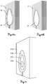
- Figs. 9a and 9b show a further embodiment according to the invention, wherein a kind of completeness check is provided to a user 100.
- the pose of the camera unit 20 with respect to the point cloud acquired from the surveying instrument can be determined, e.g. based on feature matching techniques or the detection of markers 6a,6b.
- This enables the display of the laser-based point cloud or the missing parts as an overlay 16 in the live image on a display 20' of the mobile camera unit 20 (here: smart-phone).
- This helps the user 100 to identify the missing parts 16 and guides him to fill e.g. respective gaps 16, i.e. capturing images which provide image data for extending or completing the surveying point cloud.
- the image-based point cloud particularly is generated in real-time, it can also be displayed on the camera unit for the guidance of the user.
- the user is provided with a real-time display of the object 10 and its parts, which are already covered (or not yet covered) by point cloud data.
- a further aspect according to the invention relates to the fusion of different kind of position data as illustrated in figs. 10a and 10b .
- the image-based position data 21 and the laser-based position data 11 may have different quality, i.e. the accuracy of the 3D coordinates of the points might be different. According to the present embodiment of the invention, this aspect is considered in the fusion of laser-based and image-based position data.
- overlapping areas 24 where point of higher quality, e.g. acquired with the surveying instrument (laser-based), and points of lower quality, e.g. acquired with the camera unit (image-based), are present a filtering based on the point quality is applied. For instance in the overlapping areas 24 the points with lower quality can be erased while the points with higher quality are kept.
- a combined point cloud is shown where with respect to the overlapping area 24 only the points of higher quality (point cloud data corresponding to point cloud 11) from the surveying instrument are present.
- Fig. 11 shows an alternative way of displaying point cloud quality according to the invention.
- a desired accuracy for the generated point cloud(s) is to be reached.
- a visualization of the quality e.g. colour-coded, helps the user to decide whether the required quality for a specific area is given or whether some additional operation have to be done to achieve the required accuracy, e.g. additional scans or capturing more images.
- the point-to-point accuracy of area 23a is 5mm
- of area 23b is 20mm
- of area 23c is 15mm
- of area 23d is 10 mm.
- Fig. 12 shows a further embodiment of the present invention and the respective method for generating a point cloud.
- homological points R1-R3 in the image from the surveying instrument 51 and the first two images 52a-b (belonging to a first series of images) from the camera, e.g. by feature matching, are identified.
- 3d-coordinates of points S1-S3 are computed by forward-intersection based on images 52a-b. Based thereon, the pose of a third image 52c (belonging to a second series of images) based on points S1-S3 is computed. If a further image 52d (also belonging to a second series of images) would contain any of points R1-R3 or T, also this point would be used for its pose determination. Thus, the pose of image 52d is determined based on points S2, S3 and T.
- a dense-matching may be applied to images which cover at least partly the scanning shadow 30, e.g. images 52a-d, to get a point cloud for this area.
- Fig. 13 shows an alternative method to pure feature matching based on two sets of images, one captured by the laser scanner 1 and the other by a camera 20, can be realised by using the laser scanner 1 itself as a feature generator.
- the laser scanner 1 in projection mode, where it generates a specific pattern 60, e.g. a stationary pattern like a checkerboard, by rotating and triggering its targeting laser system synchronously according to that pattern 60.
- the pattern itself can be arbitrary, e.g. a coded marker, single points, crossing lines as well as its generation.
- the generation is not limited to the procedure mentioned above (rotation and triggering of the laser beam) as it is also possible to project a single measured point complemented with a well known fixed pattern/geometry generated by a stencil (no rotation of the scanner needed).
- the proposed strategy is useful in situations where the scene/environment does not offer feature points that are traceable in a stable manner for the camera system 20, e.g. plain homogenous surfaces.
- the main advantage is that there is no need to search for features in images/point clouds of both systems (scanner 1 and camera 20), but only in the camera images 20, because the projected feature points are already known, particularly labelled, and highly accurate referenced in the scanner coordinate system.
- a possible workflow could be as follows: first, the scene is captured by doing a scan with the laser scanner 1. When the task is completed the laser scanner 1 is switched into projection mode and a pattern is projected onto a surface (not necessarily in an already scanned region). Second, the mobile camera 20 is used to perform an additional scan of another region, e.g. disjoint to the first scanned region, such that during the recording the projected pattern 60 of the laser scanner 1 is at least seen once in a camera image. Finally, using an automatic (preferred) or manual detection of all feature points of the pattern 60 the absolute orientation and position of the camera 20 referenced in the scanner coordinate system can be determined. In particular, advanced algorithms can be used for most accurate and reliable feature detection, e.g. colour-based and/or template based detection.
- the housing of the scanner itself for positioning of a marker (not shown).
- the advantage of the proposal is again the knowledge of well-defined anchor points (feature points) tracked on the marker with respect to the coordinate system of the laser scanner, as the marker's position and orientation can be factory pre-calibrated.
- the workflow is similar to the one described above, where now the user during the second scan with the mobile camera has to ensure, that the scanner housing is seen at least once in a recorded image.
- the position and orientation of the camera with relation to the coordinate system of the laser scanner is known, and subsequently, the generated point clouds (scanner and camera) can be merged easily.
Claims (15)
- Procédé de fourniture d'un nuage de points en 3D (11, 21, 31, 12, 13), en particulier d'un objet (5, 10, 10a), à l'aide d'un instrument de relevé géodésique (1, 2), en particulier un appareil de balayage laser ou une station totale, et une unité de capture d'image (20, 22), comprenant• le balayage d'un environnement avec l'instrument de relevé (1, 2) selon une région de balayage définie (5, 10, 10a) et la génération d'un nuage de points de balayage (5a, 11, 12) correspondant à la région de balayage en référence à un système de coordonnées de relevé qui est défini par l'instrument de relevé (1, 2),• la capture d'une première série d'au moins deux images (52a à c, 52g à h, 62a à d) avec l'unité de capture d'image (20, 22), les images (52a à c, 52g à h, 62a à d) ayant des poses respectives et couvrent en partie la région de balayage et une région d'imagerie, et• l'application d'un algorithme Structure from Motion (SfM) ou SLAMcaractérisé en ce que• une première image (51, 61a à d) est générée par l'instrument de relevé (1, 2) couvrant une région correspondant au moins grossièrement à la région de balayage, la première image (51, 61a à d) représentant une image de référence dont la pose est connue en référence au système de coordonnées de relevé en raison de la position et de l'orientation de l'instrument de relevé (1, 2) pour acquérir des données sur lesquelles est basée la première image (51, 61a à d),• et l'algorithme Structure from Motion (SfM) ou SLAM, respectivement, comprenant au moinso l'identification d'un premier jeu de points d'image (53a à d, R1 à R3, 63) d'après l'image de référence (51, 61a à d) et la première série d'au moins deux images (52a à c, 52g à h, 62a à d), les points d'image (53a à d, R1 à R3, 63) représentant un premier jeu de points de référence (53a à d, R1 à R3, 63) d'un champ de points de référence, dans lequel chaque point du premier jeu de points de référence (53a à d, R1 à R3) apparaît dans l'image de référence (51, 61a à d) et dans au moins l'une des images de la première série d'images (52a à c, 52g à h, 62a à d) et des informations de position concernant les points du premier jeu de points de référence (53a à d, R1 à R3) sont fournies par le nuage de points de balayage (5a, 11, 12), eto la détermination des poses pour les images de la première série d'images (52a à c, 52g à h, 62a à d) en référence au système de coordonnées de relevé, en particulier d'après un recoupement, à l'aide du premier jeu de points de référence (53a à d, R1 à R3) et de leurs informations de position, les poses représentant des positions et orientations respectives de l'unité de capture d'image (20, 22) par rapport à l'instrument de relevé (1, 2) lors de la capture des images de la première série d'images (52a à c, 52g à h, 62a à d) .
- Procédé selon la revendication 1,
caractérisé par
la détermination d'un second jeu de points de référence (54a à c, 55a à b, S1 à S3) dans une région d'imagerie d'après les poses pour les images de la première série d'images (52a à c, 52g à h, 62a à d), en particulier par intersection avant, dans lequel• la région d'imagerie est différente de la région de balayage et• une information de position concernant une position en 3D d'au moins un point du second jeu de points de référence (54a à c, 55a à b, S1 à S3) est dérivée, l'information de position étant référencée au système de coordonnées de relevé,en particulier dans lequel le nuage de points de balayage (5a, 11, 12) est actualisé en ajoutant l'information de position en 3D dérivée au nuage de points de balayage (5a, 11, 12). - Procédé selon la revendication 2,
caractérisé par• la capture d'une seconde série d'au moins une image (52c à f) avec l'unité de capture d'image (20, 22), dans lequel l'au moins une image de la seconde série couvre au moins en partie le second jeu de points de référence (54a à c, 55a à b, S1 à S3) et/ou au moins un point du premier jeu de points de référence (53a à d, R1 à R3, 63),• la détermination de la pose pour l'au moins une image (52c à f) de la seconde série en référence au système de coordonnées de relevé, en particulier d'après un recoupement, à l'aide d'au moins trois points de référence du premier (53a à d, R1 à R3, 63) et/ou du second jeu (54a à c, 55a à b, S1 à S3) de points de référence couverts par l'au moins une image (52c à f) et à l'aide de l'information de position respective. - Procédé selon la revendication 3,
caractérisé par
la détermination de la pose pour au moins une image (52c à f) de la seconde série en référence au système de coordonnées de relevé seulement à l'aide de points de référence du second jeu (54a à c, 55a à b, S1 à S3) de points de référence. - Procédé selon la revendication 3 ou 4,
caractérisé en ce que
au moins l'une des images de la seconde série d'au moins une image (52c à f) couvre en partie la région de balayage, dans lequel un point de référence supplémentaire (T) est déterminé d'après l'image de référence (51, 61a à d) et l'au moins une des images de la seconde série d'au moins une image (52c à f). - Procédé selon l'une quelconque des revendications 3 à 5,
caractérisé par
l'application d'une procédure de compensation par gerbes en fonction des poses des images de la première série d'au moins deux images (52a à c, 52g à h, 62a à d) et de la seconde série d'au moins une image (52c à f) et du premier (53a à d, R1 à R3, 63) et du second (54a à c, 55a à b, S1 à S3) jeu de points de référence, en particulier le point de référence supplémentaire (T) et/ou les données du nuage de points de balayage. - Procédé selon l'une quelconque des revendications 1 à 6,
caractérisé par
le calcul d'un nuage de points d'image (5b, 13, 21), en particulier par application d'un algorithme d'appariement dense, pour au moins une partie de la région d'imagerie d'après les poses d'au moins deux des images (51, 52a à h, 62a à d) capturées avec l'unité de capture d'image (20, 22), en particulier par intersection avant, le nuage de points d'image (5b, 13, 21) comprenant au moins une information de position en 3D selon une région communément couverte respective des au moins deux images capturées (51, 61a à d, 52a à h, 62a à d), en particulier de l'objet (5, 10, 10a), et étant référencé par rapport au système de coordonnées de relevé. - Procédé selon l'une quelconque des revendications 1 à 7,
caractérisé par
la compensation d'erreurs de position apparaissant avec le calcul de l'information de position en 3D ou des poses d'images sur la base des données du nuage de points de balayage, en particulier dans lequel la compensation est réalisée pour chaque donnée d'image successive fournie par des images capturées successivement (52a à h, 62a à d) avec l'unité de capture d'image (20, 22). - Procédé selon la revendication 7 ou 8,
caractérisé en ce que
une information de qualité concernant la précision de position de points du nuage de points de balayage (5a, 11, 12) et de points du nuage de points d'image (5b, 13, 21) est générée. - Procédé selon la revendication 9,
caractérisé en ce que
l'information de qualité est affichée dans une image, dans lequel une première région représentant le nuage de points de balayage (5a, 11, 12) est recouverte par un premier repère et une seconde région représentant le nuage de points d'image (5b, 13, 21) est recouverte par un deuxième repère, les repères étant en particulier représentés par des régions de couleurs différentes, en particulier dans lequel• une région (24) couverte à la fois par le nuage de points de balayage et le nuage de points d'image est couverte par un troisième repère ou• les points de la région (24) couverte à la fois par le nuage de points de balayage et le nuage de points d'image sont filtrés pour que seuls des points du nuage de points de balayage (5a, 11, 12) ou seuls des points du nuage de points d'image (5b, 13, 21) soient fournis, en particulier dans lequel le filtrage est induit par une entrée d'un opérateur (100). - Procédé selon l'une quelconque des revendications 1 à 10,
caractérisé en ce que
l'instrument de relevé (1, 2) et l'unité de capture d'image (20, 22) étant structurellement séparés l'un de l'autre, en particulier dans lequel l'unité de capture d'image prend la forme d'une caméra numérique mobile ou est fournie par un téléphone mobile. - Procédé selon l'une quelconque des revendications 1 à 11,
caractérisé en ce que
le procédé est conduit directement et instantanément, en particulier automatiquement, pendant un processus de mesure, dans lequel un traitement de données, en particulier concernant l'algorithme Structure from Motion (SfM) ou SLAM, est réalisé par une unité de traitement pendant le processus de mesure, l'unité de traitement recevant des données par rapport• au balayage de l'environnement,• à la génération de la première image (51, 61a à d) sur le côté de l'instrument de relevé (1, 2) et• à la capture d'au moins deux images supplémentaires (52a à c, 52g à h, 62a à d) avec l'unité de capture d'image (20, 22). - Procédé selon l'une quelconque des revendications 1 à 12,
caractérisé en ce que
une image en direct est affichée sur le côté de l'unité de capture d'image (20, 22) imageant un champ de vision effectif de l'unité de capture d'image (20, 22), dans lequel une région (16) qui est à la fois effectivement imagée par l'unité de capture d'image et couverte ou non couverte par le nuage de points de balayage (5a, 11, 12) est repérée dans l'image en direct, en particulier dans lequel une partie de l'objet qui est couvert par l'une des images (51, 52a à h, 62a à d) capturées par l'unité de capture d'image (20, 22) est repérée dans l'image en direct. - Système de fourniture d'un nuage de points en 3D, en particulier d'un objet (5, 10, 10a) à mesurer, comprenant• un instrument de relevé géodésique (1, 2), en particulier un appareil de balayage laser ou une station totale, avec∘ une structure de support montée sur une base de l'instrument de relevé (1, 2) de sorte que la structure de support puisse pivoter autour d'un premier axe défini par la base,∘ une source de rayonnement électromagnétique pour générer un faisceau de mesure,∘ une unité de direction pour diriger le faisceau de mesure, l'unité de direction étant agencée au niveau de la structure de support de manière à assurer une aptitude au pivotement de l'unité de direction autour d'un second axe défini par la structure de support, le second axe étant grossièrement perpendiculaire au premier axe,∘ une fonctionnalité de balayage pour assurer une direction et un guidage du faisceau de mesure de manière prédéfinie et mesurer des distances en correspondance, dans lequel un environnement selon une région de balayage définie peut être mesuré et dans lequel un nuage de points de balayage (5a, 11, 12) peut être produit d'après celui-ci en référence à un système de coordonnées de relevé qui est défini par l'instrument de relevé (1, 2), et∘ une fonctionnalité de génération d'image pour générer une première image (51, 61a à d), dans lequel une région correspondant au moins grossièrement à la région de balayage est couverte et dans lequel la pose de la première image est connue en référence au système de coordonnées de relevé en raison de la position et de l'orientation de l'instrument de relevé (1, 2) pour acquérir des données sur lesquelles est basée la première image (51, 61a à d),• une unité de capture d'image (20, 22) pour capturer une première série d'au moins deux images (52a à c, 52g à h, 62a à d) avec des poses respectives, la première série d'au moins deux images (52a à c, 52g à h, 62a à d) pouvant être capturée pour que la région de balayage soit en partie couverte, l'unité de capture d'image (20, 22) étant structurellement séparée de l'instrument de relevé (1, 2), et• une unité de commande et de traitement (4) pour recevoir et traiter des données depuis l'instrument de relevé (1, 2) et l'unité de capture d'image (20, 22), caractérisé en ce quel'unité de commande et de traitement (4) fournit un algorithme Structure from Motion (SfM) ou SLAM qui est au moins défini par le fait d'assurer l'exécution des étapes de• spécification que la première image représente une image de référence (51, 61a à d) et identification d'un premier jeu de points d'image (53a à d, R1 à R3, 63) d'après l'image de référence (51, 61a à d) et la première série d'au moins deux images (52a à c, 52g à h, 62a à d), les points d'image (53a à d, R1 à R3, 63) représentant un premier jeu de points de référence (53a à d) d'un champ de point de référence, dans lequel chaque point du premier jeu de points de référence (53a à d, R1 à R3) apparaît dans l'image de référence (51, 61a à d) et dans au moins l'une des images de la première série d'images (52a à c, 52g à h, 62a à d) et des informations de position concernant le premier jeu de points de référence (53a à d, R1 à R3) sont fournies par le nuage de points de balayage (5a, 11, 12), et• détermination des poses pour les images de la première série d'images (52a à c, 52g à h, 62a à d) en référence au système de coordonnées de relevé, en particulier d'après un recoupement, à l'aide du premier jeu de points de référence (53a à d, R1 à R3) et de l'information de position, les poses représentant des positions et orientations de l'unité de capture d'image (20, 22) par rapport à l'instrument de relevé (1, 2) lors de la capture des images de la première série d'au moins deux images (52a à c, 52g à h, 62a à d).
- Produit programme d'ordinateur ayant des instructions exécutables par ordinateur implémentées pour réaliser un algorithme Structure from Motion (SfM) ou SLAM selon un procédé de l'une quelconque des revendications 1 à 13 basé sur• la réception d'un nuage de points de balayage,• la réception d'une image de référence et• la réception d'au moins deux images de la première série d'au moins deux images,en particulier lorsqu'il est mis en oeuvre sur une unité de commande et de traitement (4) d'un système selon la revendication 14.
Priority Applications (3)
| Application Number | Priority Date | Filing Date | Title |
|---|---|---|---|
| EP15164442.4A EP3086283B1 (fr) | 2015-04-21 | 2015-04-21 | Fourniture d'un nuage de points à l'aide d'un instrument de surveillance et un dispositif de caméra |
| US15/132,837 US10041793B2 (en) | 2015-04-21 | 2016-04-19 | Providing a point cloud using a surveying instrument and a camera device |
| CN201610247861.9A CN106066173B (zh) | 2015-04-21 | 2016-04-20 | 提供3d点云的方法和系统及存储介质 |
Applications Claiming Priority (1)
| Application Number | Priority Date | Filing Date | Title |
|---|---|---|---|
| EP15164442.4A EP3086283B1 (fr) | 2015-04-21 | 2015-04-21 | Fourniture d'un nuage de points à l'aide d'un instrument de surveillance et un dispositif de caméra |
Publications (2)
| Publication Number | Publication Date |
|---|---|
| EP3086283A1 EP3086283A1 (fr) | 2016-10-26 |
| EP3086283B1 true EP3086283B1 (fr) | 2019-01-16 |
Family
ID=53180513
Family Applications (1)
| Application Number | Title | Priority Date | Filing Date |
|---|---|---|---|
| EP15164442.4A Active EP3086283B1 (fr) | 2015-04-21 | 2015-04-21 | Fourniture d'un nuage de points à l'aide d'un instrument de surveillance et un dispositif de caméra |
Country Status (3)
| Country | Link |
|---|---|
| US (1) | US10041793B2 (fr) |
| EP (1) | EP3086283B1 (fr) |
| CN (1) | CN106066173B (fr) |
Families Citing this family (61)
| Publication number | Priority date | Publication date | Assignee | Title |
|---|---|---|---|---|
| EP3246660B1 (fr) * | 2016-05-19 | 2019-10-30 | Hexagon Technology Center GmbH | Système et procédé permettant de référencer un dispositif d'affichage par rapport à un instrument de surveillance |
| EP3485112B1 (fr) | 2016-07-15 | 2021-08-25 | Fastbrick IP Pty Ltd | Véhicule qui incorpore une machine à poser les briques |
| BR112019000722B1 (pt) | 2016-07-15 | 2023-03-28 | Fastbrick Ip Pty Ltd | Lança extensível telescópica para transportar item e lança dobrável |
| JP6773503B2 (ja) * | 2016-09-27 | 2020-10-21 | 株式会社トプコン | レーザスキャナシステム及び点群データのレジストレーション方法 |
| EP3333538B1 (fr) | 2016-12-07 | 2020-09-09 | Hexagon Technology Center GmbH | Scanner vis |
| US10563980B2 (en) * | 2016-12-23 | 2020-02-18 | Topcon Positioning Systems, Inc. | Enhanced remote surveying systems and methods |
| US11430148B2 (en) * | 2016-12-28 | 2022-08-30 | Datalogic Ip Tech S.R.L. | Apparatus and method for pallet volume dimensioning through 3D vision capable unmanned aerial vehicles (UAV) |
| EP3351899B1 (fr) | 2017-01-24 | 2020-06-17 | Leica Geosystems AG | Procédé et dispositif pour la colorisation de nuages de points tridimensionnels |
| WO2018142493A1 (fr) * | 2017-01-31 | 2018-08-09 | 富士通株式会社 | Dispositif de traitement d'image, procédé de traitement d'image, programme de traitement d'image, procédé de capture d'image et objet mobile |
| CN106996770A (zh) * | 2017-04-07 | 2017-08-01 | 赵�怡 | 一种结合空间定位扫描及智能终端的空间测绘系统及方法 |
| JP6708790B2 (ja) | 2017-05-16 | 2020-06-10 | 富士フイルム株式会社 | 画像生成装置、画像生成システム、画像生成方法、及び画像生成プログラム |
| US10341618B2 (en) | 2017-05-24 | 2019-07-02 | Trimble Inc. | Infrastructure positioning camera system |
| US10300573B2 (en) | 2017-05-24 | 2019-05-28 | Trimble Inc. | Measurement, layout, marking, firestop stick |
| CN110770540B (zh) * | 2017-05-31 | 2024-04-09 | 宝马股份公司 | 用于构建环境模型的方法和装置 |
| EP3415866B1 (fr) | 2017-06-12 | 2020-06-03 | Hexagon Technology Center GmbH | Dispositif, système et procédé d'affichage d'écarts de mesure |
| CN107341814B (zh) * | 2017-06-14 | 2020-08-18 | 宁波大学 | 基于稀疏直接法的四旋翼无人机单目视觉测程方法 |
| WO2019006511A1 (fr) | 2017-07-05 | 2019-01-10 | Fastbrick Ip Pty Ltd | Dispositif de suivi de position et d'orientation en temps réel |
| CN111213098B (zh) | 2017-08-17 | 2024-03-15 | 快砖知识产权私人有限公司 | 用于交互系统的通信系统 |
| EP3669138B1 (fr) | 2017-08-17 | 2023-05-24 | Fastbrick IP Pty Ltd | Dispositif de poursuite laser à mesure d'angle de roulis améliorée |
| CN107453811B (zh) * | 2017-08-23 | 2019-12-03 | 佛山市南海区广工大数控装备协同创新研究院 | 一种基于可见光视觉通信的无人机协同slam的方法 |
| EP3460394B1 (fr) * | 2017-09-26 | 2020-06-03 | Hexagon Technology Center GmbH | Instrument d'arpentage, système de réalité augmentée (ra) et procédé de référencement d'un dispositif de ra relatif à un système de référence |
| WO2019065536A1 (fr) * | 2017-09-26 | 2019-04-04 | パナソニック インテレクチュアル プロパティ コーポレーション オブ アメリカ | Procédé de reconfiguration et dispositif de reconfiguration |
| AU2018348785A1 (en) | 2017-10-11 | 2020-05-07 | Fastbrick Ip Pty Ltd | Machine for conveying objects and multi-bay carousel for use therewith |
| WO2019082797A1 (fr) * | 2017-10-23 | 2019-05-02 | パナソニック インテレクチュアル プロパティ コーポレーション オブ アメリカ | Procédé de reconfiguration et dispositif de reconfiguration |
| CN108389256B (zh) * | 2017-11-23 | 2022-03-01 | 千寻位置网络有限公司 | 二三维交互式无人机电力杆塔巡检辅助方法 |
| GB2569656B (en) * | 2017-12-22 | 2020-07-22 | Zivid Labs As | Method and system for generating a three-dimensional image of an object |
| EP3524926B1 (fr) * | 2018-02-08 | 2020-05-20 | Leica Geosystems AG | Système de réalité augmentée avec fonctionnalité de définition de périmètres et méthode d'inspection correspondante |
| GB201802113D0 (en) | 2018-02-09 | 2018-03-28 | Soletanche Freyssinet Sas | System for and method of surveying a surface |
| CN112106109A (zh) * | 2018-02-16 | 2020-12-18 | 3 形状股份有限公司 | 具有表面区分的口腔内扫描 |
| CN109102537B (zh) * | 2018-06-25 | 2020-03-20 | 中德人工智能研究院有限公司 | 一种二维激光雷达和球幕相机结合的三维建模方法和系统 |
| CN109141364B (zh) * | 2018-08-01 | 2020-11-03 | 北京进化者机器人科技有限公司 | 障碍物检测方法、系统及机器人 |
| CN109352646B (zh) * | 2018-09-30 | 2023-01-06 | 泰安康平纳机械有限公司 | 纱线自动装卸方法及系统 |
| KR102640871B1 (ko) | 2018-10-30 | 2024-02-27 | 삼성전자주식회사 | 증강 현실을 이용한 영상 데이터를 제공하는 전자 장치 및 그 제어 방법 |
| DE102018218611B4 (de) | 2018-10-31 | 2022-02-10 | Audi Ag | Verfahren und Recheneinrichtung zum Erzeugen eines dreidimensionalen CAD-Modells |
| CN109484630B (zh) * | 2018-11-23 | 2020-09-08 | 四川大学 | 一种用于复杂地形的多向测绘用架设支架 |
| CN109697753B (zh) * | 2018-12-10 | 2023-10-03 | 智灵飞(北京)科技有限公司 | 一种基于rgb-d slam的无人机三维重建方法、无人机 |
| CN109636848B (zh) * | 2018-12-17 | 2020-12-25 | 武汉天乾科技有限责任公司 | 一种基于无人机的油气管道巡检方法 |
| CN109658450B (zh) * | 2018-12-17 | 2020-10-13 | 武汉天乾科技有限责任公司 | 一种基于无人机的快速正射影像生成方法 |
| US10866322B2 (en) * | 2018-12-31 | 2020-12-15 | Datalogic Usa, Inc. | Identification of shadowing on flat-top volumetric objects scanned by laser scanning devices |
| CN109819177B (zh) * | 2019-01-17 | 2021-09-03 | 湖南拓视觉信息技术有限公司 | 场景扫描方法及场景扫描仪 |
| FR3093215B1 (fr) * | 2019-02-22 | 2021-08-27 | Fogale Nanotech | Procédé et dispositif de surveillance de l’environnement d’un robot |
| DE102019108426A1 (de) * | 2019-04-01 | 2020-10-01 | Fraunhofer-Gesellschaft zur Förderung der angewandten Forschung e.V. | Vorrichtung und Verfahren zum dreidimensionalen Erfassen wenigstens eines Objekts |
| US10984240B2 (en) | 2019-04-08 | 2021-04-20 | Faro Technologies, Inc. | Localization and projection in buildings based on a reference system |
| CN110084851B (zh) * | 2019-04-19 | 2020-12-04 | 湖北亿咖通科技有限公司 | 一种双目点云生成方法及系统 |
| CN112146564B (zh) * | 2019-06-28 | 2022-04-15 | 先临三维科技股份有限公司 | 三维扫描方法、装置、计算机设备和计算机可读存储介质 |
| CN112305940A (zh) * | 2019-07-26 | 2021-02-02 | 华能国际电力股份有限公司海门电厂 | 一种堆取料机智能化监控系统及方法 |
| EP3783385A1 (fr) * | 2019-08-23 | 2021-02-24 | Leica Geosystems AG | Génération combinée de nuages de points à l'aide d'un scanner laser stationnaire et d'un scanner mobile |
| CN110569805B (zh) * | 2019-09-10 | 2023-05-05 | 南京林业大学 | 一种基于无人机影像点云的人工林单木提取及立地质量评价的方法 |
| CN110889364A (zh) * | 2019-11-21 | 2020-03-17 | 大连理工大学 | 一种利用红外传感器和可见光传感器构建栅格地图的方法 |
| US11710247B2 (en) | 2020-01-30 | 2023-07-25 | Unity Technologies Sf | System for image compositing including training with synthetic data |
| US11676252B2 (en) | 2020-01-31 | 2023-06-13 | Unity Technologies Sf | Image processing for reducing artifacts caused by removal of scene elements from images |
| US11288493B2 (en) * | 2020-02-25 | 2022-03-29 | Raytheon Company | Point cloud registration with error propagation |
| US11694313B2 (en) * | 2020-02-28 | 2023-07-04 | Unity Technologies Sf | Computer-generated image processing including volumetric scene reconstruction |
| US20210274091A1 (en) | 2020-02-28 | 2021-09-02 | Weta Digital Limited | Reconstruction of obscured views of captured imagery using arbitrary captured inputs |
| US20210274092A1 (en) | 2020-02-28 | 2021-09-02 | Weta Digital Limited | Reconstruction of obscured views in captured imagery using pixel replacement from secondary imagery |
| CN111951314B (zh) * | 2020-08-21 | 2021-08-31 | 贝壳找房(北京)科技有限公司 | 点云配准方法和装置、计算机可读存储介质、电子设备 |
| US11216005B1 (en) * | 2020-10-06 | 2022-01-04 | Accenture Global Solutions Limited | Generating a point cloud capture plan |
| US20220318540A1 (en) * | 2021-04-02 | 2022-10-06 | Faro Technologies, Inc. | Automated update of object-models in geometrical digital representation |
| CN113607730A (zh) * | 2021-08-03 | 2021-11-05 | 无锡乾鹏医疗科技有限公司 | 零件检测方法、装置、终端及可读存储介质 |
| US20230154020A1 (en) * | 2021-11-15 | 2023-05-18 | Faro Technologies, Inc. | Markerless registration of image and laser scan data |
| CN117315183B (zh) * | 2023-11-30 | 2024-02-23 | 四川鼎鸿智电装备科技有限公司 | 一种基于激光雷达构建三维地图和作业分析的方法 |
Family Cites Families (7)
| Publication number | Priority date | Publication date | Assignee | Title |
|---|---|---|---|---|
| JP5057734B2 (ja) | 2006-09-25 | 2012-10-24 | 株式会社トプコン | 測量方法及び測量システム及び測量データ処理プログラム |
| US8494285B2 (en) * | 2010-12-09 | 2013-07-23 | The Hong Kong University Of Science And Technology | Joint semantic segmentation of images and scan data |
| EP2511659A1 (fr) | 2011-04-14 | 2012-10-17 | Hexagon Technology Center GmbH | Système de marquage géodésique pour le marquage de points de mire |
| EP2511658A1 (fr) | 2011-04-14 | 2012-10-17 | Hexagon Technology Center GmbH | Système de mesure et procédé de détermination de nouveau point |
| EP2787322B1 (fr) * | 2013-04-05 | 2017-10-04 | Leica Geosystems AG | Référencement géodésique de nuages de points |
| US10234287B2 (en) * | 2014-05-05 | 2019-03-19 | Hexagon Technology Center Gmbh | Surveying system |
| EP3021078B1 (fr) * | 2014-11-14 | 2018-09-26 | Leica Geosystems AG | Système de relevé géodésique avec une caméra virtuelle |
-
2015
- 2015-04-21 EP EP15164442.4A patent/EP3086283B1/fr active Active
-
2016
- 2016-04-19 US US15/132,837 patent/US10041793B2/en active Active
- 2016-04-20 CN CN201610247861.9A patent/CN106066173B/zh active Active
Non-Patent Citations (1)
| Title |
|---|
| None * |
Also Published As
| Publication number | Publication date |
|---|---|
| CN106066173A (zh) | 2016-11-02 |
| EP3086283A1 (fr) | 2016-10-26 |
| CN106066173B (zh) | 2019-08-20 |
| US10041793B2 (en) | 2018-08-07 |
| US20160314593A1 (en) | 2016-10-27 |
Similar Documents
| Publication | Publication Date | Title |
|---|---|---|
| EP3086283B1 (fr) | Fourniture d'un nuage de points à l'aide d'un instrument de surveillance et un dispositif de caméra | |
| CN108171733B (zh) | 使两个或更多个三维3d点云配准的方法 | |
| US9898821B2 (en) | Determination of object data by template-based UAV control | |
| EP3550513B1 (fr) | Procédé de génération de vues panoramiques sur un système mobile de cartographie | |
| US9719781B2 (en) | Measuring method and measuring instrument | |
| US11544860B2 (en) | Combined point cloud generation using a stationary laser scanner and a mobile scanner | |
| EP3246660A1 (fr) | Système et procédé permettant de référencer un dispositif d'affichage par rapport à un instrument de surveillance | |
| AU2013379669B2 (en) | Apparatus and method for three dimensional surface measurement | |
| CN108227929B (zh) | 基于bim技术的增强现实放样系统及实现方法 | |
| JP6551623B1 (ja) | 情報処理装置、移動体、画像処理システムおよび情報処理方法 | |
| US9797719B2 (en) | Measuring method and measuring instrument | |
| US10890447B2 (en) | Device, system and method for displaying measurement gaps | |
| KR20200064542A (ko) | 드론을 이용한 지상기준점 측량장치 및 그 방법 | |
| JPWO2020003497A1 (ja) | 撮像装置の校正装置、監視装置、作業機械および校正方法 | |
| JP4852006B2 (ja) | 空間情報データベース生成装置及び空間情報データベース生成プログラム | |
| US11927692B2 (en) | Correcting positions after loop closure in simultaneous localization and mapping algorithm | |
| CN113984019A (zh) | 测量系统、测量方法以及测量用程序 | |
| EP4332631A1 (fr) | Procédés d'optimisation globale pour scanners de coordonnées mobiles | |
| US20230324558A1 (en) | Sensor field-of-view manipulation | |
| US20240112327A1 (en) | Bar arrangement inspection system and bar arrangement inspection method | |
| JP2022109642A (ja) | 配管竣工図作成システム、及び配管竣工図作成方法 | |
| Goeman et al. | Automatic camera to laser calibration for high accuracy mobile mapping systems using INS | |
| OA17428A (en) | Apparatus and method for three dimensional surface measurement. | |
| CZ2009354A3 (cs) | Zpusob porizování vektorových 3D dat povrchu telesa a zarízení k provádení tohoto zpusobu |
Legal Events
| Date | Code | Title | Description |
|---|---|---|---|
| PUAI | Public reference made under article 153(3) epc to a published international application that has entered the european phase |
Free format text: ORIGINAL CODE: 0009012 |
|
| AK | Designated contracting states |
Kind code of ref document: A1 Designated state(s): AL AT BE BG CH CY CZ DE DK EE ES FI FR GB GR HR HU IE IS IT LI LT LU LV MC MK MT NL NO PL PT RO RS SE SI SK SM TR |
|
| AX | Request for extension of the european patent |
Extension state: BA ME |
|
| STAA | Information on the status of an ep patent application or granted ep patent |
Free format text: STATUS: REQUEST FOR EXAMINATION WAS MADE |
|
| 17P | Request for examination filed |
Effective date: 20170413 |
|
| RBV | Designated contracting states (corrected) |
Designated state(s): AL AT BE BG CH CY CZ DE DK EE ES FI FR GB GR HR HU IE IS IT LI LT LU LV MC MK MT NL NO PL PT RO RS SE SI SK SM TR |
|
| RIN1 | Information on inventor provided before grant (corrected) |
Inventor name: METZLER, BERNHARD Inventor name: VELIZHEV, ALEXANDER Inventor name: FIDLER, THOMAS |
|
| REG | Reference to a national code |
Ref country code: DE Ref legal event code: R079 Ref document number: 602015023485 Country of ref document: DE Free format text: PREVIOUS MAIN CLASS: G06T0007000000 Ipc: G06T0007330000 |
|
| GRAP | Despatch of communication of intention to grant a patent |
Free format text: ORIGINAL CODE: EPIDOSNIGR1 |
|
| STAA | Information on the status of an ep patent application or granted ep patent |
Free format text: STATUS: GRANT OF PATENT IS INTENDED |
|
| RIC1 | Information provided on ipc code assigned before grant |
Ipc: G06T 7/33 20170101AFI20180830BHEP Ipc: G06T 7/521 20170101ALI20180830BHEP Ipc: G06T 7/38 20170101ALI20180830BHEP Ipc: H04N 5/232 20060101ALI20180830BHEP Ipc: G01C 15/00 20060101ALI20180830BHEP Ipc: G06T 7/73 20170101ALI20180830BHEP Ipc: G06T 7/579 20170101ALI20180830BHEP |
|
| INTG | Intention to grant announced |
Effective date: 20181001 |
|
| GRAS | Grant fee paid |
Free format text: ORIGINAL CODE: EPIDOSNIGR3 |
|
| GRAA | (expected) grant |
Free format text: ORIGINAL CODE: 0009210 |
|
| STAA | Information on the status of an ep patent application or granted ep patent |
Free format text: STATUS: THE PATENT HAS BEEN GRANTED |
|
| AK | Designated contracting states |
Kind code of ref document: B1 Designated state(s): AL AT BE BG CH CY CZ DE DK EE ES FI FR GB GR HR HU IE IS IT LI LT LU LV MC MK MT NL NO PL PT RO RS SE SI SK SM TR |
|
| REG | Reference to a national code |
Ref country code: GB Ref legal event code: FG4D |
|
| REG | Reference to a national code |
Ref country code: CH Ref legal event code: EP Ref country code: CH Ref legal event code: NV Representative=s name: KAMINSKI HARMANN PATENTANWAELTE AG, LI |
|
| REG | Reference to a national code |
Ref country code: IE Ref legal event code: FG4D |
|
| REG | Reference to a national code |
Ref country code: DE Ref legal event code: R096 Ref document number: 602015023485 Country of ref document: DE |
|
| REG | Reference to a national code |
Ref country code: AT Ref legal event code: REF Ref document number: 1090280 Country of ref document: AT Kind code of ref document: T Effective date: 20190215 |
|
| REG | Reference to a national code |
Ref country code: SE Ref legal event code: TRGR |
|
| REG | Reference to a national code |
Ref country code: NL Ref legal event code: FP |
|
| REG | Reference to a national code |
Ref country code: LT Ref legal event code: MG4D |
|
| REG | Reference to a national code |
Ref country code: AT Ref legal event code: MK05 Ref document number: 1090280 Country of ref document: AT Kind code of ref document: T Effective date: 20190116 |
|
| PG25 | Lapsed in a contracting state [announced via postgrant information from national office to epo] |
Ref country code: FI Free format text: LAPSE BECAUSE OF FAILURE TO SUBMIT A TRANSLATION OF THE DESCRIPTION OR TO PAY THE FEE WITHIN THE PRESCRIBED TIME-LIMIT Effective date: 20190116 Ref country code: LT Free format text: LAPSE BECAUSE OF FAILURE TO SUBMIT A TRANSLATION OF THE DESCRIPTION OR TO PAY THE FEE WITHIN THE PRESCRIBED TIME-LIMIT Effective date: 20190116 Ref country code: PL Free format text: LAPSE BECAUSE OF FAILURE TO SUBMIT A TRANSLATION OF THE DESCRIPTION OR TO PAY THE FEE WITHIN THE PRESCRIBED TIME-LIMIT Effective date: 20190116 Ref country code: NO Free format text: LAPSE BECAUSE OF FAILURE TO SUBMIT A TRANSLATION OF THE DESCRIPTION OR TO PAY THE FEE WITHIN THE PRESCRIBED TIME-LIMIT Effective date: 20190416 Ref country code: PT Free format text: LAPSE BECAUSE OF FAILURE TO SUBMIT A TRANSLATION OF THE DESCRIPTION OR TO PAY THE FEE WITHIN THE PRESCRIBED TIME-LIMIT Effective date: 20190516 Ref country code: ES Free format text: LAPSE BECAUSE OF FAILURE TO SUBMIT A TRANSLATION OF THE DESCRIPTION OR TO PAY THE FEE WITHIN THE PRESCRIBED TIME-LIMIT Effective date: 20190116 |
|
| PG25 | Lapsed in a contracting state [announced via postgrant information from national office to epo] |
Ref country code: LV Free format text: LAPSE BECAUSE OF FAILURE TO SUBMIT A TRANSLATION OF THE DESCRIPTION OR TO PAY THE FEE WITHIN THE PRESCRIBED TIME-LIMIT Effective date: 20190116 Ref country code: RS Free format text: LAPSE BECAUSE OF FAILURE TO SUBMIT A TRANSLATION OF THE DESCRIPTION OR TO PAY THE FEE WITHIN THE PRESCRIBED TIME-LIMIT Effective date: 20190116 Ref country code: IS Free format text: LAPSE BECAUSE OF FAILURE TO SUBMIT A TRANSLATION OF THE DESCRIPTION OR TO PAY THE FEE WITHIN THE PRESCRIBED TIME-LIMIT Effective date: 20190516 Ref country code: BG Free format text: LAPSE BECAUSE OF FAILURE TO SUBMIT A TRANSLATION OF THE DESCRIPTION OR TO PAY THE FEE WITHIN THE PRESCRIBED TIME-LIMIT Effective date: 20190416 Ref country code: HR Free format text: LAPSE BECAUSE OF FAILURE TO SUBMIT A TRANSLATION OF THE DESCRIPTION OR TO PAY THE FEE WITHIN THE PRESCRIBED TIME-LIMIT Effective date: 20190116 Ref country code: GR Free format text: LAPSE BECAUSE OF FAILURE TO SUBMIT A TRANSLATION OF THE DESCRIPTION OR TO PAY THE FEE WITHIN THE PRESCRIBED TIME-LIMIT Effective date: 20190417 |
|
| REG | Reference to a national code |
Ref country code: DE Ref legal event code: R097 Ref document number: 602015023485 Country of ref document: DE |
|
| PG25 | Lapsed in a contracting state [announced via postgrant information from national office to epo] |
Ref country code: DK Free format text: LAPSE BECAUSE OF FAILURE TO SUBMIT A TRANSLATION OF THE DESCRIPTION OR TO PAY THE FEE WITHIN THE PRESCRIBED TIME-LIMIT Effective date: 20190116 Ref country code: EE Free format text: LAPSE BECAUSE OF FAILURE TO SUBMIT A TRANSLATION OF THE DESCRIPTION OR TO PAY THE FEE WITHIN THE PRESCRIBED TIME-LIMIT Effective date: 20190116 Ref country code: AT Free format text: LAPSE BECAUSE OF FAILURE TO SUBMIT A TRANSLATION OF THE DESCRIPTION OR TO PAY THE FEE WITHIN THE PRESCRIBED TIME-LIMIT Effective date: 20190116 Ref country code: AL Free format text: LAPSE BECAUSE OF FAILURE TO SUBMIT A TRANSLATION OF THE DESCRIPTION OR TO PAY THE FEE WITHIN THE PRESCRIBED TIME-LIMIT Effective date: 20190116 Ref country code: SK Free format text: LAPSE BECAUSE OF FAILURE TO SUBMIT A TRANSLATION OF THE DESCRIPTION OR TO PAY THE FEE WITHIN THE PRESCRIBED TIME-LIMIT Effective date: 20190116 Ref country code: CZ Free format text: LAPSE BECAUSE OF FAILURE TO SUBMIT A TRANSLATION OF THE DESCRIPTION OR TO PAY THE FEE WITHIN THE PRESCRIBED TIME-LIMIT Effective date: 20190116 Ref country code: RO Free format text: LAPSE BECAUSE OF FAILURE TO SUBMIT A TRANSLATION OF THE DESCRIPTION OR TO PAY THE FEE WITHIN THE PRESCRIBED TIME-LIMIT Effective date: 20190116 Ref country code: IT Free format text: LAPSE BECAUSE OF FAILURE TO SUBMIT A TRANSLATION OF THE DESCRIPTION OR TO PAY THE FEE WITHIN THE PRESCRIBED TIME-LIMIT Effective date: 20190116 |
|
| PLBE | No opposition filed within time limit |
Free format text: ORIGINAL CODE: 0009261 |
|
| STAA | Information on the status of an ep patent application or granted ep patent |
Free format text: STATUS: NO OPPOSITION FILED WITHIN TIME LIMIT |
|
| PG25 | Lapsed in a contracting state [announced via postgrant information from national office to epo] |
Ref country code: SM Free format text: LAPSE BECAUSE OF FAILURE TO SUBMIT A TRANSLATION OF THE DESCRIPTION OR TO PAY THE FEE WITHIN THE PRESCRIBED TIME-LIMIT Effective date: 20190116 |
|
| REG | Reference to a national code |
Ref country code: BE Ref legal event code: MM Effective date: 20190430 |
|
| 26N | No opposition filed |
Effective date: 20191017 |
|
| PG25 | Lapsed in a contracting state [announced via postgrant information from national office to epo] |
Ref country code: MC Free format text: LAPSE BECAUSE OF FAILURE TO SUBMIT A TRANSLATION OF THE DESCRIPTION OR TO PAY THE FEE WITHIN THE PRESCRIBED TIME-LIMIT Effective date: 20190116 Ref country code: LU Free format text: LAPSE BECAUSE OF NON-PAYMENT OF DUE FEES Effective date: 20190421 |
|
| PG25 | Lapsed in a contracting state [announced via postgrant information from national office to epo] |
Ref country code: BE Free format text: LAPSE BECAUSE OF NON-PAYMENT OF DUE FEES Effective date: 20190430 Ref country code: SI Free format text: LAPSE BECAUSE OF FAILURE TO SUBMIT A TRANSLATION OF THE DESCRIPTION OR TO PAY THE FEE WITHIN THE PRESCRIBED TIME-LIMIT Effective date: 20190116 |
|
| PG25 | Lapsed in a contracting state [announced via postgrant information from national office to epo] |
Ref country code: TR Free format text: LAPSE BECAUSE OF FAILURE TO SUBMIT A TRANSLATION OF THE DESCRIPTION OR TO PAY THE FEE WITHIN THE PRESCRIBED TIME-LIMIT Effective date: 20190116 |
|
| PG25 | Lapsed in a contracting state [announced via postgrant information from national office to epo] |
Ref country code: IE Free format text: LAPSE BECAUSE OF NON-PAYMENT OF DUE FEES Effective date: 20190421 |
|
| PGFP | Annual fee paid to national office [announced via postgrant information from national office to epo] |
Ref country code: CH Payment date: 20200420 Year of fee payment: 6 Ref country code: NL Payment date: 20200427 Year of fee payment: 6 |
|
| PGFP | Annual fee paid to national office [announced via postgrant information from national office to epo] |
Ref country code: SE Payment date: 20200427 Year of fee payment: 6 |
|
| PG25 | Lapsed in a contracting state [announced via postgrant information from national office to epo] |
Ref country code: CY Free format text: LAPSE BECAUSE OF FAILURE TO SUBMIT A TRANSLATION OF THE DESCRIPTION OR TO PAY THE FEE WITHIN THE PRESCRIBED TIME-LIMIT Effective date: 20190116 |
|
| PG25 | Lapsed in a contracting state [announced via postgrant information from national office to epo] |
Ref country code: MT Free format text: LAPSE BECAUSE OF FAILURE TO SUBMIT A TRANSLATION OF THE DESCRIPTION OR TO PAY THE FEE WITHIN THE PRESCRIBED TIME-LIMIT Effective date: 20190116 Ref country code: HU Free format text: LAPSE BECAUSE OF FAILURE TO SUBMIT A TRANSLATION OF THE DESCRIPTION OR TO PAY THE FEE WITHIN THE PRESCRIBED TIME-LIMIT; INVALID AB INITIO Effective date: 20150421 |
|
| REG | Reference to a national code |
Ref country code: SE Ref legal event code: EUG |
|
| REG | Reference to a national code |
Ref country code: NL Ref legal event code: MM Effective date: 20210501 |
|
| PG25 | Lapsed in a contracting state [announced via postgrant information from national office to epo] |
Ref country code: LI Free format text: LAPSE BECAUSE OF NON-PAYMENT OF DUE FEES Effective date: 20210430 Ref country code: CH Free format text: LAPSE BECAUSE OF NON-PAYMENT OF DUE FEES Effective date: 20210430 Ref country code: SE Free format text: LAPSE BECAUSE OF NON-PAYMENT OF DUE FEES Effective date: 20210422 |
|
| PG25 | Lapsed in a contracting state [announced via postgrant information from national office to epo] |
Ref country code: NL Free format text: LAPSE BECAUSE OF NON-PAYMENT OF DUE FEES Effective date: 20210501 |
|
| PG25 | Lapsed in a contracting state [announced via postgrant information from national office to epo] |
Ref country code: MK Free format text: LAPSE BECAUSE OF FAILURE TO SUBMIT A TRANSLATION OF THE DESCRIPTION OR TO PAY THE FEE WITHIN THE PRESCRIBED TIME-LIMIT Effective date: 20190116 |
|
| PGFP | Annual fee paid to national office [announced via postgrant information from national office to epo] |
Ref country code: FR Payment date: 20230424 Year of fee payment: 9 Ref country code: DE Payment date: 20220620 Year of fee payment: 9 |
|
| PGFP | Annual fee paid to national office [announced via postgrant information from national office to epo] |
Ref country code: GB Payment date: 20230419 Year of fee payment: 9 |