EP3333351B1 - Verbindungsanordnung zum verbinden eines pfostens mit einem rahmenprofil eines fensters oder einer türe aus kunststoff - Google Patents
Verbindungsanordnung zum verbinden eines pfostens mit einem rahmenprofil eines fensters oder einer türe aus kunststoff Download PDFInfo
- Publication number
- EP3333351B1 EP3333351B1 EP17193228.8A EP17193228A EP3333351B1 EP 3333351 B1 EP3333351 B1 EP 3333351B1 EP 17193228 A EP17193228 A EP 17193228A EP 3333351 B1 EP3333351 B1 EP 3333351B1
- Authority
- EP
- European Patent Office
- Prior art keywords
- latching
- post
- connection arrangement
- base part
- arrangement according
- Prior art date
- Legal status (The legal status is an assumption and is not a legal conclusion. Google has not performed a legal analysis and makes no representation as to the accuracy of the status listed.)
- Active
Links
Images

Classifications
-
- E—FIXED CONSTRUCTIONS
- E06—DOORS, WINDOWS, SHUTTERS, OR ROLLER BLINDS IN GENERAL; LADDERS
- E06B—FIXED OR MOVABLE CLOSURES FOR OPENINGS IN BUILDINGS, VEHICLES, FENCES OR LIKE ENCLOSURES IN GENERAL, e.g. DOORS, WINDOWS, BLINDS, GATES
- E06B3/00—Window sashes, door leaves, or like elements for closing wall or like openings; Layout of fixed or moving closures, e.g. windows in wall or like openings; Features of rigidly-mounted outer frames relating to the mounting of wing frames
- E06B3/96—Corner joints or edge joints for windows, doors, or the like frames or wings
- E06B3/964—Corner joints or edge joints for windows, doors, or the like frames or wings using separate connection pieces, e.g. T-connection pieces
- E06B3/9642—Butt type joints with at least one frame member cut off square; T-shape joints
-
- E—FIXED CONSTRUCTIONS
- E06—DOORS, WINDOWS, SHUTTERS, OR ROLLER BLINDS IN GENERAL; LADDERS
- E06B—FIXED OR MOVABLE CLOSURES FOR OPENINGS IN BUILDINGS, VEHICLES, FENCES OR LIKE ENCLOSURES IN GENERAL, e.g. DOORS, WINDOWS, BLINDS, GATES
- E06B3/00—Window sashes, door leaves, or like elements for closing wall or like openings; Layout of fixed or moving closures, e.g. windows in wall or like openings; Features of rigidly-mounted outer frames relating to the mounting of wing frames
- E06B3/96—Corner joints or edge joints for windows, doors, or the like frames or wings
- E06B3/964—Corner joints or edge joints for windows, doors, or the like frames or wings using separate connection pieces, e.g. T-connection pieces
- E06B3/968—Corner joints or edge joints for windows, doors, or the like frames or wings using separate connection pieces, e.g. T-connection pieces characterised by the way the connecting pieces are fixed in or on the frame members
- E06B3/9684—Corner joints or edge joints for windows, doors, or the like frames or wings using separate connection pieces, e.g. T-connection pieces characterised by the way the connecting pieces are fixed in or on the frame members by hooking protrusions on the connecting piece in openings of the frame member, e.g. by snap-locking
Definitions
- the invention relates to a connection arrangement for connecting a post with a frame profile of a window or a door made of plastic, wherein the post has a hollow profile and is secured to the frame profile by means of a post connector having a base part which is mounted on the frame profile, and an over this arranged
- Aufjobeil comprises, which is connected to the post and is positively guided when plugging onto the base part, wherein in the assembled state
- Aufmyeil and base are fastened together.
- connection arrangement of this kind is z. B. in the EP 2 354 419 A2 described.
- the base part of the post connector is placed on a profiled top of a frame profile and fastened there via several screws on this.
- the Aufsteckteil in turn projects beyond an upper mold section in the hollow section of the post, where it is positively inserted into the latter so far until the lower end surface of the post against the upper support surface of the Aufsteckmaschines comes to a stop.
- About mounted in Aufsteckteil bores of the inserted into the hollow profile of the post upper mold portion of the Aufsteckmaschines be fastened by means guided through the holes screws on the post.
- connection arrangement with the features of the preamble of claim 1 is made DE 197 45 750 A1 known.
- the invention aims to improve a connection arrangement of the type mentioned so that it can be mounted faster with a simplified installation effort.
- the invention also leads to a lower use of materials, since the screws to be used in the known post connectors for their attachment to the frame or post replacement omitted.
- the locking elements used in the invention on the male part and the base part easily during injection molding of these plastic parts together be prepared with these, so that no additional manufacturing steps are required for this.
- the required for the production of the locking elements additional cost of materials is very low, especially compared with the cost of materials for the spare attributable screws.
- the plug-on part can be placed vertically from above onto the base part.
- the locking elements are designed in the form of projecting, elastically deflectable spring hooks which are provided with latching hooks at their projecting ends, each of these latching hooks in the assembled state in each case in an associated receiving opening in a wall of the part to be connected engaging latching.
- the elastically deflectable spring hooks are preferably provided at their latching hooks with inlet slopes, which cause during assembly an automatic elastic rebound of each spring hook before its entry into its latching position.
- all latching connections are detachable, so that at any time by a suitable solution engagement, a repeal of each created by the relevant locking connection attachment of two parts from each other is possible.
- a further advantageous embodiment of the invention is also that all locking elements, which serve on Aufsteckteil and the base part for locking on the post or on the frame section, at the other of the two parts in each case a support member is assigned, which in mounted state of the arrangement bears against the respective associated locking element and this is supported so that a Ausrastiolo from the detent position is not possible.
- the locking elements are provided in the form of elastically spring spring hooks each with a central, opposite to the projecting end of the spring hook end of the same open center hole, in which the locking element associated with this support member during assembly of the base member and Aufsteckteil insertable is.
- the support member is not applied laterally against the spring hook from the outside during assembly, but rather introduced into the center hole mounted in this, so that it supports the spring hook from its interior against a disengagement.
- it is recommended that some or all support members are cylindrical.
- At least four, particularly six locking elements for locking the post can be attached to the Aufsteckteil, with a larger or smaller number of such locking elements can be provided.
- connection arrangement according to the invention If in the connection arrangement according to the invention the individual locking elements associated support members are used, then it is advisable to provide them with a shape which in the mounted state with a complementary shape either on the support member facing the rear side of the associated locking element or on one of the back the latching element opposite rear side of the support member adjacent wall is in a positive connection, which blocks in a movement against the mounting direction of the Aufpersoneiles on the base member, but allows a movement of the support member relative to the locking element in Aufsetzraum.
- the connection arrangement according to the invention initially results in a particularly rapid acceleration of the assembly, which can be carried out completely without the use of screws. In the case of automatic assembly lines, it is possible to reduce the cycle time for the assembly of the post connector to one second (or even less).
- connection arrangement according to the invention is also relatively simple in construction, it can be handled easily and it can be used easily on a frame welding machine.
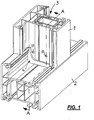
- Fig. 1 an oblique perspective view of a connection arrangement in which a post 1 (of which only the lower end portion is shown), which is provided with a hollow profile 3, is fixed via a post connector 4 on the top of a post 1 perpendicular to the frame profile 2, wherein the Post connector 4 is shown mounted on a profiled surface of the frame strip 2.
- Post 1 frame profile 2 and post connector 4 are all made of a suitable plastic.
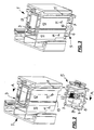
- the post connector 4 in turn, consists of Fig. 1 is not recognizable and will be described in detail below, from two parts, namely an upper Aufsteckteil 5, from which an oblique view from above in Fig. 2 is reproduced below the representation of the post 1, and a lying in the assembled state below the embarkckvons 5 base part 9 (see 6 and 7 ).
- the Aufsteckteil 5 is positively inserted with its upper portion in the lower end portion of the post 1 in the hollow section 3, wherein Fig. 3 represents this Einschiebevorgang, but in a state in which the plug-5 is not yet fully inserted into the post 1.
- the Aufsteckteil 5 comprises a base plate 6, from which a plurality of shapes, such as Fig. 2 shows, run vertically upwards, while other shapes that will be discussed, projecting on the bottom of the base plate 6 downwards.
- each of these locking elements 7 protrude from the base plate 6 a plurality of locking elements 7 in the form of elastic spring hooks vertically upwards, each of these locking elements 7 is provided at its free projecting end with a latching hook 8 which protrudes from the locking element 7 perpendicular to the outer side surface.
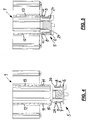
- Fig. 4 shows a sectional view along section AA through the configuration of the arrangement Fig. 2 and Fig. 5 shows the sectional view Fig. 4 , but with completely pushed into the hollow section 3 of the post 1 Aufsteckteil. 5
- FIG. 4 shows the arrangement of the through holes 11 in the side walls 12 and 13 of the hollow section 3 of the post 1, which are offset from the lower end face 10 of the post 1 by a distance such that when fully pushed on the plug 5, the locking hooks 8 of the elastic locking elements. 7 completely engaged in the respective associated bore 11.
- each locking element 7 outwardly projecting latching hooks 8 which are each provided with an insertion bevel 26 at the top, at the inlet into the hollow section 3 on the inner sides of the respective assigned Side walls 12 and 13 of the post 1 deflected so that when further pushing the respective projecting free end of each latching hook 8 runs along the inside of the associated side wall 12 and 13, with the result that the elastic locking element 7 something in the direction of the Inside the hollow section 3 of the post 1 is deflected resiliently.
- the latching hooks 8 of the latching elements 7 reach the hole 11 provided for each of them, in which they then engage automatically on insertion due to the elastic deflection of the latching elements 7.
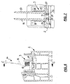
- Fig. 6 is a section through a frame profile 2 shown, on the upper side of the lower base part 9 of a post connector 4 is mounted.
- the base part shown here 9 of the post connector 4 carries an upwardly projecting mold projection 14, which enters in the mounted state of the overall arrangement in a formed in the hollow section 3 of the post 1 hollow chamber.
- Such an embodiment of the base part 9 of a post connector is in the German Patent application no. 10 2015 112 563.3 of July 30, 2015 described in detail, with reference to the embodiment described there is specifically referenced.
- the base part 9 of the post connector 4 comprises, as Fig. 6 shows, a support plate 15 which is supported in the mounted on the frame profile 2 state against the top of the frame profile 2. From the support plate 15, the mold projection 14 protrudes upward, perpendicular to the plane of the support plate 15, upwards, being supported on both sides thereof by a reinforcing rib 16 or 17 extending over almost its entire height.
- the molding projection 14 in its thickened lower portion on both sides of an area parallel to each other (and directed transversely to the longitudinal direction of the profile frame 2) locking teeth 18.
- Fig. 7 finally shows an enlarged sectional view according to cutting position CC Fig. 6 ,
- FIG. 7 shows are on the frame profile 2 facing bottom of the support plate 15 of the base member 9 downward resilient locking elements in the form of spring hooks 19 are attached, which are provided at their free projecting ends with radially outwardly directed latching hooks 20.
- the latching hooks 20 are arranged in mutually opposite directions, namely radially outward.
- spring hooks 19 engage through a correspondingly mounted in the wall of the frame section 2 opening 21 through, where they immediately below after passing through the opening 21 with its outwardly directed latching hook 20 the local opening edge of the opening 21 under the outside. It can, as in the illustration according to Fig. 7 However, only two such spring hooks 19 associated with the opening 21, it can around the circumference of the opening 21 around but also more than two, z. B. three or four, spring hooks 19 are arranged.
- the length of the spring hooks 19 is just chosen so that rest in the mounted state of the latching hook 20 against the underside of the wall of the frame profile 2, in which the bore 21 is mounted, latching.
- the base part 9 of the post connector 4 can on the top of the frame profile 2 with this over such a latching arrangement, as in Fig. 7 is shown to be connected and thereby represent a sufficiently strong latching connection.
- several such locking arrangements can be attached to the support plate 15, so that they can be connected in the assembled state and at several points by latching with the frame section 2.
- the shaping projection 14 is cut in the region of its two lateral reinforcing ribs 16, 17, wherein a plurality of locking teeth 18 are formed on each of these reinforcing ribs in their lower region on their outer side facing away from the other reinforcing rib.
- the locking teeth 18 and the locking counter teeth 22 are formed so that they allow in the direction of Aufsteckschul of Aufsteck learners 5 on the base part 9 relative movement of both parts to each other, although they are in the opposite direction, however, the desired locking connection is present and a relative movement the parts is prevented from each other in this direction.
- Fig. 8 can also be removed, protrude from the support plate 15 of the base member 9 vertically upwards elastic support members 23 which are integrally formed with the support plate 15 and inserted into corresponding receiving openings 24 in the plug-5. These support members 23 reinforce in this inserted position, the total rigidity of the Aufsteckvons 5 in the areas where locking engagements are formed, in such a way that the interlocking elements with each other can not perform a catching action canceling relative movement.
Landscapes
- Engineering & Computer Science (AREA)
- Civil Engineering (AREA)
- Structural Engineering (AREA)
- Mutual Connection Of Rods And Tubes (AREA)
- Joining Of Corner Units Of Frames Or Wings (AREA)
Priority Applications (1)
| Application Number | Priority Date | Filing Date | Title |
|---|---|---|---|
| PL17193228T PL3333351T3 (pl) | 2016-12-08 | 2017-09-26 | Układ łączący do łączenia słupka z profilem ramy okna lub drzwi z tworzywa sztucznego |
Applications Claiming Priority (1)
| Application Number | Priority Date | Filing Date | Title |
|---|---|---|---|
| DE102016123889.9A DE102016123889A1 (de) | 2016-12-08 | 2016-12-08 | Verbindungsanordnung zum Verbinden eines Pfostens mit einem Rahmenprofil eines Fensters oder einer Türe aus Kunststoff |
Publications (2)
| Publication Number | Publication Date |
|---|---|
| EP3333351A1 EP3333351A1 (de) | 2018-06-13 |
| EP3333351B1 true EP3333351B1 (de) | 2019-11-20 |
Family
ID=59969080
Family Applications (1)
| Application Number | Title | Priority Date | Filing Date |
|---|---|---|---|
| EP17193228.8A Active EP3333351B1 (de) | 2016-12-08 | 2017-09-26 | Verbindungsanordnung zum verbinden eines pfostens mit einem rahmenprofil eines fensters oder einer türe aus kunststoff |
Country Status (4)
| Country | Link |
|---|---|
| EP (1) | EP3333351B1 (pl) |
| DE (1) | DE102016123889A1 (pl) |
| ES (1) | ES2771298T3 (pl) |
| PL (1) | PL3333351T3 (pl) |
Families Citing this family (4)
| Publication number | Priority date | Publication date | Assignee | Title |
|---|---|---|---|---|
| DE102017122328A1 (de) * | 2017-09-26 | 2019-03-28 | PHI Technik für Fenster und Türen GmbH | Verfahren und Verbindungsanordnung zum Verbinden eines Pfostens mit einem Rahmenprofil bei einem Fenster oder einer Türe aus Kunststoff |
| CN111702720A (zh) * | 2020-07-14 | 2020-09-25 | 江长征 | 一种型材快速拆装机构 |
| DE202020107218U1 (de) | 2020-12-14 | 2022-03-15 | REHAU Industries SE & Co. KG | Verbinder zur mechanischen Verbindung von Rahmenprofilen mit Pfosten-, Kämpfer- oder Sprossenprofilen im Fenster- und Türenbau sowie diesen umfassende Verbindung |
| CN112855679A (zh) * | 2021-03-08 | 2021-05-28 | 河北聚源水利机械有限公司 | 一种用于闸门的榫卯结构 |
Citations (1)
| Publication number | Priority date | Publication date | Assignee | Title |
|---|---|---|---|---|
| DE4442074A1 (de) * | 1994-11-25 | 1996-05-30 | Fickenscher Gealan Werk Gmbh | Pfosten-, Sprossen- und Kreuzverbinder |
Family Cites Families (7)
| Publication number | Priority date | Publication date | Assignee | Title |
|---|---|---|---|---|
| US5205102A (en) * | 1991-04-18 | 1993-04-27 | Andersen Corporation | Corner fastener for hollow section members |
| DE19607786C2 (de) * | 1996-03-01 | 2002-11-21 | Harman Audio Electronic Sys | Verbindungselement |
| DE19745750C5 (de) * | 1997-10-16 | 2008-10-02 | Hans Dieter Grotefeld | Kämpfer-Verbinder für Fenster- und Türrahmen |
| DE20019534U1 (de) * | 2000-11-17 | 2001-01-18 | REHAU AG + Co., 95111 Rehau | Verbinder |
| DE102007053525A1 (de) * | 2007-11-09 | 2009-06-10 | Inoutic / Deceuninck Gmbh | Schwellenverbinder |
| DE102010007181B4 (de) | 2010-02-08 | 2018-03-01 | PHI Technik für Fenster und Türen GmbH | Pfostenverbinder |
| DE102015112563A1 (de) | 2015-07-30 | 2017-02-02 | PHI Technik für Fenster und Türen GmbH | Verbindungsanordnung zum Verbinden eines Pfostens an einem Rahmenprofil eines Fensters oder einer Türe aus Kunststoff |
-
2016
- 2016-12-08 DE DE102016123889.9A patent/DE102016123889A1/de not_active Withdrawn
-
2017
- 2017-09-26 PL PL17193228T patent/PL3333351T3/pl unknown
- 2017-09-26 ES ES17193228T patent/ES2771298T3/es active Active
- 2017-09-26 EP EP17193228.8A patent/EP3333351B1/de active Active
Patent Citations (1)
| Publication number | Priority date | Publication date | Assignee | Title |
|---|---|---|---|---|
| DE4442074A1 (de) * | 1994-11-25 | 1996-05-30 | Fickenscher Gealan Werk Gmbh | Pfosten-, Sprossen- und Kreuzverbinder |
Also Published As
| Publication number | Publication date |
|---|---|
| DE102016123889A1 (de) | 2018-06-14 |
| EP3333351A1 (de) | 2018-06-13 |
| PL3333351T3 (pl) | 2020-05-18 |
| ES2771298T3 (es) | 2020-07-06 |
Similar Documents
| Publication | Publication Date | Title |
|---|---|---|
| EP0643911B1 (de) | Zerlegbarer Käfig | |
| DE602004001734T2 (de) | Ein Befestigungselement zur Verbindung von an einem Trägerteil | |
| DE102006019959B4 (de) | Tankklappe für Automobile | |
| AT510774B1 (de) | Befestigungsvorrichtung für wandteile | |
| EP3585211B1 (de) | Anordnung mit möbelteile und verbindungsstift | |
| EP3333351B1 (de) | Verbindungsanordnung zum verbinden eines pfostens mit einem rahmenprofil eines fensters oder einer türe aus kunststoff | |
| EP1084655A1 (de) | Befestigungsanordnung | |
| EP3568610B1 (de) | Trennsteg für energieführungsketten | |
| DE102009012438A1 (de) | Pfostenverbinder | |
| EP0589170B1 (de) | Treibstangenbeschlag für Fenster, Türen od. dgl. | |
| DE102015112563A1 (de) | Verbindungsanordnung zum Verbinden eines Pfostens an einem Rahmenprofil eines Fensters oder einer Türe aus Kunststoff | |
| EP2407604B1 (de) | Verbindungsvorrichtung | |
| EP0773615B1 (de) | Schaltschrank für elektrische Anlagen | |
| DE19923487B4 (de) | Widerlager mit Formteil zum Befestigen von Betätigungszügen | |
| DE4006213A1 (de) | Vorrichtung zur aufnahme eines tafelelements | |
| DE3816516A1 (de) | Sockel fuer einen schaltschrank oder dergleichen | |
| DE2715830A1 (de) | Moebelartikel | |
| DE202009003438U1 (de) | Pfostenverbinder | |
| WO1993006639A1 (de) | Filter-stecker | |
| EP1962388B1 (de) | Rahmen für elektrische Schalter und Steckdosen | |
| EP0722208A2 (de) | Anordnung zur Einbauhalterung von Elektro-Installationsgeräten | |
| EP0853353B1 (de) | Kontaktfeder-Einheit für elektrische Schaltfunktionen | |
| DE102020123839B4 (de) | Verbindungselement für ein Möbelstück, Stecksystem mit einem solchen Verbindungselement und ein Verfahren zur Montage eines Möbelstücks | |
| EP0556442A1 (de) | Treibstangenbeschlag für Fenster, Türen od. dgl. | |
| DE3521014C2 (pl) |
Legal Events
| Date | Code | Title | Description |
|---|---|---|---|
| PUAI | Public reference made under article 153(3) epc to a published international application that has entered the european phase |
Free format text: ORIGINAL CODE: 0009012 |
|
| STAA | Information on the status of an ep patent application or granted ep patent |
Free format text: STATUS: THE APPLICATION HAS BEEN PUBLISHED |
|
| AK | Designated contracting states |
Kind code of ref document: A1 Designated state(s): AL AT BE BG CH CY CZ DE DK EE ES FI FR GB GR HR HU IE IS IT LI LT LU LV MC MK MT NL NO PL PT RO RS SE SI SK SM TR |
|
| AX | Request for extension of the european patent |
Extension state: BA ME |
|
| STAA | Information on the status of an ep patent application or granted ep patent |
Free format text: STATUS: REQUEST FOR EXAMINATION WAS MADE |
|
| 17P | Request for examination filed |
Effective date: 20181213 |
|
| RBV | Designated contracting states (corrected) |
Designated state(s): AL AT BE BG CH CY CZ DE DK EE ES FI FR GB GR HR HU IE IS IT LI LT LU LV MC MK MT NL NO PL PT RO RS SE SI SK SM TR |
|
| GRAP | Despatch of communication of intention to grant a patent |
Free format text: ORIGINAL CODE: EPIDOSNIGR1 |
|
| STAA | Information on the status of an ep patent application or granted ep patent |
Free format text: STATUS: GRANT OF PATENT IS INTENDED |
|
| INTG | Intention to grant announced |
Effective date: 20190613 |
|
| GRAS | Grant fee paid |
Free format text: ORIGINAL CODE: EPIDOSNIGR3 |
|
| GRAA | (expected) grant |
Free format text: ORIGINAL CODE: 0009210 |
|
| STAA | Information on the status of an ep patent application or granted ep patent |
Free format text: STATUS: THE PATENT HAS BEEN GRANTED |
|
| AK | Designated contracting states |
Kind code of ref document: B1 Designated state(s): AL AT BE BG CH CY CZ DE DK EE ES FI FR GB GR HR HU IE IS IT LI LT LU LV MC MK MT NL NO PL PT RO RS SE SI SK SM TR |
|
| REG | Reference to a national code |
Ref country code: GB Ref legal event code: FG4D Free format text: NOT ENGLISH |
|
| REG | Reference to a national code |
Ref country code: CH Ref legal event code: EP |
|
| REG | Reference to a national code |
Ref country code: DE Ref legal event code: R096 Ref document number: 502017002913 Country of ref document: DE |
|
| REG | Reference to a national code |
Ref country code: IE Ref legal event code: FG4D Free format text: LANGUAGE OF EP DOCUMENT: GERMAN |
|
| REG | Reference to a national code |
Ref country code: AT Ref legal event code: REF Ref document number: 1204384 Country of ref document: AT Kind code of ref document: T Effective date: 20191215 |
|
| REG | Reference to a national code |
Ref country code: NL Ref legal event code: FP |
|
| REG | Reference to a national code |
Ref country code: LT Ref legal event code: MG4D |
|
| PG25 | Lapsed in a contracting state [announced via postgrant information from national office to epo] |
Ref country code: SE Free format text: LAPSE BECAUSE OF FAILURE TO SUBMIT A TRANSLATION OF THE DESCRIPTION OR TO PAY THE FEE WITHIN THE PRESCRIBED TIME-LIMIT Effective date: 20191120 Ref country code: NO Free format text: LAPSE BECAUSE OF FAILURE TO SUBMIT A TRANSLATION OF THE DESCRIPTION OR TO PAY THE FEE WITHIN THE PRESCRIBED TIME-LIMIT Effective date: 20200220 Ref country code: LV Free format text: LAPSE BECAUSE OF FAILURE TO SUBMIT A TRANSLATION OF THE DESCRIPTION OR TO PAY THE FEE WITHIN THE PRESCRIBED TIME-LIMIT Effective date: 20191120 Ref country code: FI Free format text: LAPSE BECAUSE OF FAILURE TO SUBMIT A TRANSLATION OF THE DESCRIPTION OR TO PAY THE FEE WITHIN THE PRESCRIBED TIME-LIMIT Effective date: 20191120 Ref country code: GR Free format text: LAPSE BECAUSE OF FAILURE TO SUBMIT A TRANSLATION OF THE DESCRIPTION OR TO PAY THE FEE WITHIN THE PRESCRIBED TIME-LIMIT Effective date: 20200221 Ref country code: LT Free format text: LAPSE BECAUSE OF FAILURE TO SUBMIT A TRANSLATION OF THE DESCRIPTION OR TO PAY THE FEE WITHIN THE PRESCRIBED TIME-LIMIT Effective date: 20191120 Ref country code: BG Free format text: LAPSE BECAUSE OF FAILURE TO SUBMIT A TRANSLATION OF THE DESCRIPTION OR TO PAY THE FEE WITHIN THE PRESCRIBED TIME-LIMIT Effective date: 20200220 |
|
| PG25 | Lapsed in a contracting state [announced via postgrant information from national office to epo] |
Ref country code: RS Free format text: LAPSE BECAUSE OF FAILURE TO SUBMIT A TRANSLATION OF THE DESCRIPTION OR TO PAY THE FEE WITHIN THE PRESCRIBED TIME-LIMIT Effective date: 20191120 Ref country code: HR Free format text: LAPSE BECAUSE OF FAILURE TO SUBMIT A TRANSLATION OF THE DESCRIPTION OR TO PAY THE FEE WITHIN THE PRESCRIBED TIME-LIMIT Effective date: 20191120 Ref country code: IS Free format text: LAPSE BECAUSE OF FAILURE TO SUBMIT A TRANSLATION OF THE DESCRIPTION OR TO PAY THE FEE WITHIN THE PRESCRIBED TIME-LIMIT Effective date: 20200320 |
|
| PG25 | Lapsed in a contracting state [announced via postgrant information from national office to epo] |
Ref country code: AL Free format text: LAPSE BECAUSE OF FAILURE TO SUBMIT A TRANSLATION OF THE DESCRIPTION OR TO PAY THE FEE WITHIN THE PRESCRIBED TIME-LIMIT Effective date: 20191120 |
|
| REG | Reference to a national code |
Ref country code: ES Ref legal event code: FG2A Ref document number: 2771298 Country of ref document: ES Kind code of ref document: T3 Effective date: 20200706 |
|
| PG25 | Lapsed in a contracting state [announced via postgrant information from national office to epo] |
Ref country code: CZ Free format text: LAPSE BECAUSE OF FAILURE TO SUBMIT A TRANSLATION OF THE DESCRIPTION OR TO PAY THE FEE WITHIN THE PRESCRIBED TIME-LIMIT Effective date: 20191120 Ref country code: RO Free format text: LAPSE BECAUSE OF FAILURE TO SUBMIT A TRANSLATION OF THE DESCRIPTION OR TO PAY THE FEE WITHIN THE PRESCRIBED TIME-LIMIT Effective date: 20191120 Ref country code: EE Free format text: LAPSE BECAUSE OF FAILURE TO SUBMIT A TRANSLATION OF THE DESCRIPTION OR TO PAY THE FEE WITHIN THE PRESCRIBED TIME-LIMIT Effective date: 20191120 Ref country code: PT Free format text: LAPSE BECAUSE OF FAILURE TO SUBMIT A TRANSLATION OF THE DESCRIPTION OR TO PAY THE FEE WITHIN THE PRESCRIBED TIME-LIMIT Effective date: 20200412 Ref country code: DK Free format text: LAPSE BECAUSE OF FAILURE TO SUBMIT A TRANSLATION OF THE DESCRIPTION OR TO PAY THE FEE WITHIN THE PRESCRIBED TIME-LIMIT Effective date: 20191120 |
|
| REG | Reference to a national code |
Ref country code: DE Ref legal event code: R097 Ref document number: 502017002913 Country of ref document: DE |
|
| PG25 | Lapsed in a contracting state [announced via postgrant information from national office to epo] |
Ref country code: SK Free format text: LAPSE BECAUSE OF FAILURE TO SUBMIT A TRANSLATION OF THE DESCRIPTION OR TO PAY THE FEE WITHIN THE PRESCRIBED TIME-LIMIT Effective date: 20191120 Ref country code: SM Free format text: LAPSE BECAUSE OF FAILURE TO SUBMIT A TRANSLATION OF THE DESCRIPTION OR TO PAY THE FEE WITHIN THE PRESCRIBED TIME-LIMIT Effective date: 20191120 |
|
| PLBE | No opposition filed within time limit |
Free format text: ORIGINAL CODE: 0009261 |
|
| STAA | Information on the status of an ep patent application or granted ep patent |
Free format text: STATUS: NO OPPOSITION FILED WITHIN TIME LIMIT |
|
| 26N | No opposition filed |
Effective date: 20200821 |
|
| PG25 | Lapsed in a contracting state [announced via postgrant information from national office to epo] |
Ref country code: SI Free format text: LAPSE BECAUSE OF FAILURE TO SUBMIT A TRANSLATION OF THE DESCRIPTION OR TO PAY THE FEE WITHIN THE PRESCRIBED TIME-LIMIT Effective date: 20191120 |
|
| PG25 | Lapsed in a contracting state [announced via postgrant information from national office to epo] |
Ref country code: LU Free format text: LAPSE BECAUSE OF NON-PAYMENT OF DUE FEES Effective date: 20200926 |
|
| PG25 | Lapsed in a contracting state [announced via postgrant information from national office to epo] |
Ref country code: IE Free format text: LAPSE BECAUSE OF NON-PAYMENT OF DUE FEES Effective date: 20200926 |
|
| PG25 | Lapsed in a contracting state [announced via postgrant information from national office to epo] |
Ref country code: TR Free format text: LAPSE BECAUSE OF FAILURE TO SUBMIT A TRANSLATION OF THE DESCRIPTION OR TO PAY THE FEE WITHIN THE PRESCRIBED TIME-LIMIT Effective date: 20191120 Ref country code: MT Free format text: LAPSE BECAUSE OF FAILURE TO SUBMIT A TRANSLATION OF THE DESCRIPTION OR TO PAY THE FEE WITHIN THE PRESCRIBED TIME-LIMIT Effective date: 20191120 Ref country code: CY Free format text: LAPSE BECAUSE OF FAILURE TO SUBMIT A TRANSLATION OF THE DESCRIPTION OR TO PAY THE FEE WITHIN THE PRESCRIBED TIME-LIMIT Effective date: 20191120 |
|
| PG25 | Lapsed in a contracting state [announced via postgrant information from national office to epo] |
Ref country code: MK Free format text: LAPSE BECAUSE OF FAILURE TO SUBMIT A TRANSLATION OF THE DESCRIPTION OR TO PAY THE FEE WITHIN THE PRESCRIBED TIME-LIMIT Effective date: 20191120 Ref country code: MC Free format text: LAPSE BECAUSE OF FAILURE TO SUBMIT A TRANSLATION OF THE DESCRIPTION OR TO PAY THE FEE WITHIN THE PRESCRIBED TIME-LIMIT Effective date: 20191120 |
|
| PGFP | Annual fee paid to national office [announced via postgrant information from national office to epo] |
Ref country code: ES Payment date: 20241028 Year of fee payment: 8 |
|
| PGFP | Annual fee paid to national office [announced via postgrant information from national office to epo] |
Ref country code: CH Payment date: 20241001 Year of fee payment: 8 |
|
| REG | Reference to a national code |
Ref country code: CH Ref legal event code: U11 Free format text: ST27 STATUS EVENT CODE: U-0-0-U10-U11 (AS PROVIDED BY THE NATIONAL OFFICE) Effective date: 20251001 |
|
| PGFP | Annual fee paid to national office [announced via postgrant information from national office to epo] |
Ref country code: DE Payment date: 20250919 Year of fee payment: 9 |
|
| PGFP | Annual fee paid to national office [announced via postgrant information from national office to epo] |
Ref country code: IT Payment date: 20250923 Year of fee payment: 9 Ref country code: PL Payment date: 20250918 Year of fee payment: 9 Ref country code: NL Payment date: 20250918 Year of fee payment: 9 |
|
| PGFP | Annual fee paid to national office [announced via postgrant information from national office to epo] |
Ref country code: BE Payment date: 20250918 Year of fee payment: 9 Ref country code: GB Payment date: 20250919 Year of fee payment: 9 |
|
| PGFP | Annual fee paid to national office [announced via postgrant information from national office to epo] |
Ref country code: FR Payment date: 20250922 Year of fee payment: 9 Ref country code: AT Payment date: 20250919 Year of fee payment: 9 |