EP3333351B1 - Connection assembly for connecting a post with a frame profile of a window or a door made of plastic - Google Patents
Connection assembly for connecting a post with a frame profile of a window or a door made of plastic Download PDFInfo
- Publication number
- EP3333351B1 EP3333351B1 EP17193228.8A EP17193228A EP3333351B1 EP 3333351 B1 EP3333351 B1 EP 3333351B1 EP 17193228 A EP17193228 A EP 17193228A EP 3333351 B1 EP3333351 B1 EP 3333351B1
- Authority
- EP
- European Patent Office
- Prior art keywords
- latching
- post
- connection arrangement
- base part
- arrangement according
- Prior art date
- Legal status (The legal status is an assumption and is not a legal conclusion. Google has not performed a legal analysis and makes no representation as to the accuracy of the status listed.)
- Active
Links
- 238000003780 insertion Methods 0.000 description 8
- 230000037431 insertion Effects 0.000 description 8
- 230000003014 reinforcing effect Effects 0.000 description 5
- 230000001133 acceleration Effects 0.000 description 3
- 238000009434 installation Methods 0.000 description 3
- 238000004519 manufacturing process Methods 0.000 description 3
- 239000000463 material Substances 0.000 description 3
- 238000005520 cutting process Methods 0.000 description 2
- 238000000034 method Methods 0.000 description 2
- 230000000295 complement effect Effects 0.000 description 1
- 238000010276 construction Methods 0.000 description 1
- 238000001746 injection moulding Methods 0.000 description 1
- 238000000465 moulding Methods 0.000 description 1
- 238000007493 shaping process Methods 0.000 description 1
- 239000000243 solution Substances 0.000 description 1
- 230000001960 triggered effect Effects 0.000 description 1
- 238000003466 welding Methods 0.000 description 1
Images

Classifications
-
- E—FIXED CONSTRUCTIONS
- E06—DOORS, WINDOWS, SHUTTERS, OR ROLLER BLINDS IN GENERAL; LADDERS
- E06B—FIXED OR MOVABLE CLOSURES FOR OPENINGS IN BUILDINGS, VEHICLES, FENCES OR LIKE ENCLOSURES IN GENERAL, e.g. DOORS, WINDOWS, BLINDS, GATES
- E06B3/00—Window sashes, door leaves, or like elements for closing wall or like openings; Layout of fixed or moving closures, e.g. windows in wall or like openings; Features of rigidly-mounted outer frames relating to the mounting of wing frames
- E06B3/96—Corner joints or edge joints for windows, doors, or the like frames or wings
- E06B3/964—Corner joints or edge joints for windows, doors, or the like frames or wings using separate connection pieces, e.g. T-connection pieces
- E06B3/9642—Butt type joints with at least one frame member cut off square; T-shape joints
-
- E—FIXED CONSTRUCTIONS
- E06—DOORS, WINDOWS, SHUTTERS, OR ROLLER BLINDS IN GENERAL; LADDERS
- E06B—FIXED OR MOVABLE CLOSURES FOR OPENINGS IN BUILDINGS, VEHICLES, FENCES OR LIKE ENCLOSURES IN GENERAL, e.g. DOORS, WINDOWS, BLINDS, GATES
- E06B3/00—Window sashes, door leaves, or like elements for closing wall or like openings; Layout of fixed or moving closures, e.g. windows in wall or like openings; Features of rigidly-mounted outer frames relating to the mounting of wing frames
- E06B3/96—Corner joints or edge joints for windows, doors, or the like frames or wings
- E06B3/964—Corner joints or edge joints for windows, doors, or the like frames or wings using separate connection pieces, e.g. T-connection pieces
- E06B3/968—Corner joints or edge joints for windows, doors, or the like frames or wings using separate connection pieces, e.g. T-connection pieces characterised by the way the connecting pieces are fixed in or on the frame members
- E06B3/9684—Corner joints or edge joints for windows, doors, or the like frames or wings using separate connection pieces, e.g. T-connection pieces characterised by the way the connecting pieces are fixed in or on the frame members by hooking protrusions on the connecting piece in openings of the frame member, e.g. by snap-locking
Definitions
- the invention relates to a connection arrangement for connecting a post with a frame profile of a window or a door made of plastic, wherein the post has a hollow profile and is secured to the frame profile by means of a post connector having a base part which is mounted on the frame profile, and an over this arranged
- Aufjobeil comprises, which is connected to the post and is positively guided when plugging onto the base part, wherein in the assembled state
- Aufmyeil and base are fastened together.
- connection arrangement of this kind is z. B. in the EP 2 354 419 A2 described.
- the base part of the post connector is placed on a profiled top of a frame profile and fastened there via several screws on this.
- the Aufsteckteil in turn projects beyond an upper mold section in the hollow section of the post, where it is positively inserted into the latter so far until the lower end surface of the post against the upper support surface of the Aufsteckmaschines comes to a stop.
- About mounted in Aufsteckteil bores of the inserted into the hollow profile of the post upper mold portion of the Aufsteckmaschines be fastened by means guided through the holes screws on the post.
- connection arrangement with the features of the preamble of claim 1 is made DE 197 45 750 A1 known.
- the invention aims to improve a connection arrangement of the type mentioned so that it can be mounted faster with a simplified installation effort.
- the invention also leads to a lower use of materials, since the screws to be used in the known post connectors for their attachment to the frame or post replacement omitted.
- the locking elements used in the invention on the male part and the base part easily during injection molding of these plastic parts together be prepared with these, so that no additional manufacturing steps are required for this.
- the required for the production of the locking elements additional cost of materials is very low, especially compared with the cost of materials for the spare attributable screws.
- the plug-on part can be placed vertically from above onto the base part.
- the locking elements are designed in the form of projecting, elastically deflectable spring hooks which are provided with latching hooks at their projecting ends, each of these latching hooks in the assembled state in each case in an associated receiving opening in a wall of the part to be connected engaging latching.
- the elastically deflectable spring hooks are preferably provided at their latching hooks with inlet slopes, which cause during assembly an automatic elastic rebound of each spring hook before its entry into its latching position.
- all latching connections are detachable, so that at any time by a suitable solution engagement, a repeal of each created by the relevant locking connection attachment of two parts from each other is possible.
- a further advantageous embodiment of the invention is also that all locking elements, which serve on Aufsteckteil and the base part for locking on the post or on the frame section, at the other of the two parts in each case a support member is assigned, which in mounted state of the arrangement bears against the respective associated locking element and this is supported so that a Ausrastiolo from the detent position is not possible.
- the locking elements are provided in the form of elastically spring spring hooks each with a central, opposite to the projecting end of the spring hook end of the same open center hole, in which the locking element associated with this support member during assembly of the base member and Aufsteckteil insertable is.
- the support member is not applied laterally against the spring hook from the outside during assembly, but rather introduced into the center hole mounted in this, so that it supports the spring hook from its interior against a disengagement.
- it is recommended that some or all support members are cylindrical.
- At least four, particularly six locking elements for locking the post can be attached to the Aufsteckteil, with a larger or smaller number of such locking elements can be provided.
- connection arrangement according to the invention If in the connection arrangement according to the invention the individual locking elements associated support members are used, then it is advisable to provide them with a shape which in the mounted state with a complementary shape either on the support member facing the rear side of the associated locking element or on one of the back the latching element opposite rear side of the support member adjacent wall is in a positive connection, which blocks in a movement against the mounting direction of the Aufpersoneiles on the base member, but allows a movement of the support member relative to the locking element in Aufsetzraum.
- the connection arrangement according to the invention initially results in a particularly rapid acceleration of the assembly, which can be carried out completely without the use of screws. In the case of automatic assembly lines, it is possible to reduce the cycle time for the assembly of the post connector to one second (or even less).
- connection arrangement according to the invention is also relatively simple in construction, it can be handled easily and it can be used easily on a frame welding machine.
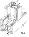
- Fig. 1 an oblique perspective view of a connection arrangement in which a post 1 (of which only the lower end portion is shown), which is provided with a hollow profile 3, is fixed via a post connector 4 on the top of a post 1 perpendicular to the frame profile 2, wherein the Post connector 4 is shown mounted on a profiled surface of the frame strip 2.
- Post 1 frame profile 2 and post connector 4 are all made of a suitable plastic.
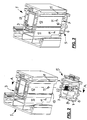
- the post connector 4 in turn, consists of Fig. 1 is not recognizable and will be described in detail below, from two parts, namely an upper Aufsteckteil 5, from which an oblique view from above in Fig. 2 is reproduced below the representation of the post 1, and a lying in the assembled state below the embarkckvons 5 base part 9 (see 6 and 7 ).
- the Aufsteckteil 5 is positively inserted with its upper portion in the lower end portion of the post 1 in the hollow section 3, wherein Fig. 3 represents this Einschiebevorgang, but in a state in which the plug-5 is not yet fully inserted into the post 1.
- the Aufsteckteil 5 comprises a base plate 6, from which a plurality of shapes, such as Fig. 2 shows, run vertically upwards, while other shapes that will be discussed, projecting on the bottom of the base plate 6 downwards.
- each of these locking elements 7 protrude from the base plate 6 a plurality of locking elements 7 in the form of elastic spring hooks vertically upwards, each of these locking elements 7 is provided at its free projecting end with a latching hook 8 which protrudes from the locking element 7 perpendicular to the outer side surface.
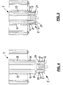
- Fig. 4 shows a sectional view along section AA through the configuration of the arrangement Fig. 2 and Fig. 5 shows the sectional view Fig. 4 , but with completely pushed into the hollow section 3 of the post 1 Aufsteckteil. 5
- FIG. 4 shows the arrangement of the through holes 11 in the side walls 12 and 13 of the hollow section 3 of the post 1, which are offset from the lower end face 10 of the post 1 by a distance such that when fully pushed on the plug 5, the locking hooks 8 of the elastic locking elements. 7 completely engaged in the respective associated bore 11.
- each locking element 7 outwardly projecting latching hooks 8 which are each provided with an insertion bevel 26 at the top, at the inlet into the hollow section 3 on the inner sides of the respective assigned Side walls 12 and 13 of the post 1 deflected so that when further pushing the respective projecting free end of each latching hook 8 runs along the inside of the associated side wall 12 and 13, with the result that the elastic locking element 7 something in the direction of the Inside the hollow section 3 of the post 1 is deflected resiliently.
- the latching hooks 8 of the latching elements 7 reach the hole 11 provided for each of them, in which they then engage automatically on insertion due to the elastic deflection of the latching elements 7.
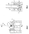
- Fig. 6 is a section through a frame profile 2 shown, on the upper side of the lower base part 9 of a post connector 4 is mounted.
- the base part shown here 9 of the post connector 4 carries an upwardly projecting mold projection 14, which enters in the mounted state of the overall arrangement in a formed in the hollow section 3 of the post 1 hollow chamber.
- Such an embodiment of the base part 9 of a post connector is in the German Patent application no. 10 2015 112 563.3 of July 30, 2015 described in detail, with reference to the embodiment described there is specifically referenced.
- the base part 9 of the post connector 4 comprises, as Fig. 6 shows, a support plate 15 which is supported in the mounted on the frame profile 2 state against the top of the frame profile 2. From the support plate 15, the mold projection 14 protrudes upward, perpendicular to the plane of the support plate 15, upwards, being supported on both sides thereof by a reinforcing rib 16 or 17 extending over almost its entire height.
- the molding projection 14 in its thickened lower portion on both sides of an area parallel to each other (and directed transversely to the longitudinal direction of the profile frame 2) locking teeth 18.
- Fig. 7 finally shows an enlarged sectional view according to cutting position CC Fig. 6 ,
- FIG. 7 shows are on the frame profile 2 facing bottom of the support plate 15 of the base member 9 downward resilient locking elements in the form of spring hooks 19 are attached, which are provided at their free projecting ends with radially outwardly directed latching hooks 20.
- the latching hooks 20 are arranged in mutually opposite directions, namely radially outward.
- spring hooks 19 engage through a correspondingly mounted in the wall of the frame section 2 opening 21 through, where they immediately below after passing through the opening 21 with its outwardly directed latching hook 20 the local opening edge of the opening 21 under the outside. It can, as in the illustration according to Fig. 7 However, only two such spring hooks 19 associated with the opening 21, it can around the circumference of the opening 21 around but also more than two, z. B. three or four, spring hooks 19 are arranged.
- the length of the spring hooks 19 is just chosen so that rest in the mounted state of the latching hook 20 against the underside of the wall of the frame profile 2, in which the bore 21 is mounted, latching.
- the base part 9 of the post connector 4 can on the top of the frame profile 2 with this over such a latching arrangement, as in Fig. 7 is shown to be connected and thereby represent a sufficiently strong latching connection.
- several such locking arrangements can be attached to the support plate 15, so that they can be connected in the assembled state and at several points by latching with the frame section 2.
- the shaping projection 14 is cut in the region of its two lateral reinforcing ribs 16, 17, wherein a plurality of locking teeth 18 are formed on each of these reinforcing ribs in their lower region on their outer side facing away from the other reinforcing rib.
- the locking teeth 18 and the locking counter teeth 22 are formed so that they allow in the direction of Aufsteckschul of Aufsteck learners 5 on the base part 9 relative movement of both parts to each other, although they are in the opposite direction, however, the desired locking connection is present and a relative movement the parts is prevented from each other in this direction.
- Fig. 8 can also be removed, protrude from the support plate 15 of the base member 9 vertically upwards elastic support members 23 which are integrally formed with the support plate 15 and inserted into corresponding receiving openings 24 in the plug-5. These support members 23 reinforce in this inserted position, the total rigidity of the Aufsteckvons 5 in the areas where locking engagements are formed, in such a way that the interlocking elements with each other can not perform a catching action canceling relative movement.
Description
Die Erfindung bezieht sich auf eine Verbindungsanordnung zum Verbinden eines Pfostens mit einem Rahmenprofil eines Fensters oder einer Türe aus Kunststoff, wobei der Pfosten ein Hohlprofil aufweist und am Rahmenprofil mittels eines Pfostenverbinders befestigt ist, der ein Basisteil, das am Rahmenprofil montiert ist, und ein über diesem angeordnetes Aufsetzteil umfaßt, das mit dem Pfosten verbunden ist und beim Aufstecken auf das Basisteil formschlüssig geführt ist, wobei im montierten Zustand Aufsetzteil und Basisteil aneinander befestigt werden.The invention relates to a connection arrangement for connecting a post with a frame profile of a window or a door made of plastic, wherein the post has a hollow profile and is secured to the frame profile by means of a post connector having a base part which is mounted on the frame profile, and an over this arranged Aufsetzteil comprises, which is connected to the post and is positively guided when plugging onto the base part, wherein in the assembled state Aufsetzteil and base are fastened together.
Eine Verbindungsanordnung dieser Art wird z. B. in der
Das Aufsteckteil seinerseits ragt über einen oberen Formabschnitt in das Hohlprofil des Pfostens vor, wobei es formschlüssig in den letzteren soweit eingeschoben ist, bis die untere Abschlußfläche des Pfostens gegen die obere Tragfläche des Aufsteckteiles zum Anschlag kommt. Über im Aufsteckteil angebrachte Bohrungen kann der in das Hohlprofil des Pfostens eingeschobene obere Formabschnitt des Aufsteckteiles mittels durch die Bohrungen hindurchgeführter Schrauben am Pfosten befestigt werden. Am Basisteil wie auch am Aufsteckteil sind außerdem, in Längsrichtung des Rahmenprofiles verlaufende, zueinander ausgerichtete Bohrungen so angebracht, daß im montierten Zustand eine durch die beiden Teile fluchtend hindurchlaufende Durchgangsbohrung entsteht. Durch ein geeignet in diese eingebrachtes Befestigungsmittel, etwa eine entsprechend lange Schraube oder ein Durchsteckbolzen o. ä., kann dann die gewünschte feste Verbindung zwischen Basisteil und Aufsteckteil geschaffen werden, welche auch die Relativposition beider Teile zueinander blockiert.The Aufsteckteil in turn projects beyond an upper mold section in the hollow section of the post, where it is positively inserted into the latter so far until the lower end surface of the post against the upper support surface of the Aufsteckteiles comes to a stop. About mounted in Aufsteckteil bores of the inserted into the hollow profile of the post upper mold portion of the Aufsteckteiles be fastened by means guided through the holes screws on the post. On the base part as well as on the Aufsteckteil also extending in the longitudinal direction of the frame profile, mutually aligned bores are mounted so that in the assembled state, a through hole passing through the two parts through hole is formed. By a suitable introduced into this fastener, such as a correspondingly long screw or a through-bolt o. Ä., Then the desired firm connection between the base part and Aufsteckteil can be created, which blocks the relative position of both parts to each other.
Dieser bekannte Pfostenverbinder ermöglicht insgesamt zwar eine relativ rasche und bequeme Montage, bei der jedoch mehrere Schrauben sowohl zur Befestigung des Basisteils am Rahmenprofil, wie auch zu der Verbindung zwischen Aufsteckteil und dem an dieses angeschlossenen Pfosten erforderlich sind, was bei der Montage solcher Pfostenverbinder noch immer einen deutlichen Aufwand zum Anbringen der erforderlichen Bohrungen für die Schrauben, auch am Rahmenprofil, sowie für den Einschraubvorgang der Schrauben bedingtAlthough this known post connector overall allows a relatively quick and convenient installation, but in which a plurality of screws are required both for attachment of the base part on the frame profile, as well as the connection between Aufsteckteil and connected to this post, which in the assembly of such post connectors yet always a significant effort for attaching the necessary holes for the screws, also on the frame profile, as well as for the screwing of the screws due
Eine Verbindungsanordnung mit den Merkmalen des Oberbegriffs des Anspruchs 1 ist aus
Hiervon ausgehend stellt die Erfindung darauf ab, eine Verbindungsanordnung der eingangs genannten Art so zu verbessern, daß sie bei vereinfachtem Montageaufwand schneller montierbar ist.On this basis, the invention aims to improve a connection arrangement of the type mentioned so that it can be mounted faster with a simplified installation effort.
Erfindungsgemäß wird dies bei einer Verbindungsanordnung der eingangs genannten Art dadurch erreicht, daß am Aufsteckteil und am Basisteil jeweils Rastelemente vorgesehen sind, mittels derer beim Zusammenbau das Aufsteckteil am Pfosten und das Basisteil am Rahmenprofi formschlüssig-verrastend befestigbar sind.According to the invention, this is achieved in a connection arrangement of the type mentioned above in that the Aufsteckteil and the base part each locking elements are provided, by means of which the Aufsteckteil on the post and the base part on the Rahmenprofi are positively fastened latching during assembly.
Durch die Verwendung von Rastelementen zwischen Aufsteckteil und Pfosten sowie Basisteil und Rahmenprofil, durch die beim Aufeinandersetzen der Einzelteile bei der Montage eine gegenseitige formschlüssig-verrastende Befestigung erreichbar ist, wird bei der Erfindung die Möglichkeit geschaffen, sowohl die Befestigung des Basisteils am Rahmenprofil, wie auch die des Aufsteckteiles am Pfosten gänzlich ohne Schrauben vornehmen zu können. Dies führt zu einer deutlich rascheren Montage, da weder das Einschrauben von Schrauben, noch das Anbringen der erforderlichen Schraublöcher im Basis- und im Aufsteckteil sowie im angeschlossenen Rahmenprofil bzw. Pfosten erforderlich ist. Dabei läßt sich auch die Taktzeit in einer automatisierten Fertigungsstraße, die bislang bei zwei Minuten pro Takt liegt, absenken und dadurch eine Beschleunigung der Montage erreichen. Denn bei der automatisierten Montage bekannter Pfostenverbinder, bei denen die Taktzeit üblicherweise, wie oben erwähnt, zwei Minuten beträgt, muß aber beim Anbringen und Befestigen über Schrauben eine deutlich längere Dauer des Taktes berücksichtigt werden. Dies bedeutet, daß hierfür der zu montierende Rahmen auf einen Sonderarbeitsplatz separiert werden muß, während in der Taktstraße mit einer Leerstelle weitergefahren wird. Zum Wiedereinfügen des Rahmens in die Taktstraße wird dann aber eine neue Leerstelle benötigt, die zu Beginn der Taktstraße geschaffen werden muß, indem dort aber bis zum Wiedereinfügen bei weiterlaufendem Band nichts vorgenommen werden muß. Dies führt insgesamt unter Berücksichtigung dieser Vorgänge zu einem Zeitverlust von vier Minuten, was, da in bekannten Taktstraßen in etwa acht Stunden ca. 240 Rahmen geschaffen werden können, insgesamt eine zeitlich merkliche Montagebeschleunigung ergibt.Through the use of locking elements between Aufsteckteil and posts and base member and frame profile through which a mutual positive-latching attachment can be achieved when placing the items in the assembly, the possibility is created in the invention, both the attachment of the base to the frame profile, as well to be able to make the Aufsteckteiles on the post entirely without screws. This leads to a much faster assembly, since neither the screwing of screws, nor the attachment of the necessary screw holes in the base and in the plug-in part and in the connected frame profile or post is required. It can also be the cycle time in an automated production line, which is currently at two minutes per clock, lower and thereby achieve an acceleration of the assembly. Because in the automated assembly of known post connectors, in which the cycle time is usually, as mentioned above, two minutes, but a much longer duration of the clock must be considered when attaching and fastening screws. This means that for this purpose the frame to be mounted must be separated on a special workplace, while in the tact line with a blank space is continued. To re-insert the frame in the bar, however, a new space is then required, which must be created at the beginning of the bar, but there must be nothing done until reinserting at weiterlaufendem tape. Taking these processes into consideration, this leads to a loss of time of four minutes, which, since approximately 240 frames can be created in known tact streets in approximately eight hours, results overall in a noticeable increase in assembly speed.
Außerdem führt die Erfindung auch zu einem geringeren Materialeinsatz, da die bei den bekannten Pfostenverbindern für deren Befestigung am Rahmen bzw. Pfosten einzusetzenden Schrauben ersatzlos entfallen. Dabei können die bei der Erfindung eingesetzten Rastelemente am Aufsteckteil und am Basisteil unschwer beim Spritzgießen dieser Kunststoffteile zusammen mit diesen hergestellt werden, so daß hierfür auch keine zusätzlichen Herstellschritte erforderlich sind. Der für die Herstellung der Rastelemente erforderliche zusätzliche Materialaufwand ist sehr gering, insbesondere verglichen mit dem Materialaufwand für die ersatzlos entfallenden Schrauben.In addition, the invention also leads to a lower use of materials, since the screws to be used in the known post connectors for their attachment to the frame or post replacement omitted. In this case, the locking elements used in the invention on the male part and the base part easily during injection molding of these plastic parts together be prepared with these, so that no additional manufacturing steps are required for this. The required for the production of the locking elements additional cost of materials is very low, especially compared with the cost of materials for the spare attributable screws.
Erfindungsgemäß wird es vorgesehen, daß für die Befestigung des Aufsetzteiles am Basisteil ebenfalls Rastelemente an diesen Teilen vorgesehen sind, mittels derer beide Teile formschlüssig-verrastend miteinander verbindbar sind. Dadurch ist es nun möglich, auch das Basisteil und das Aufsteckteil ohne Schrauben, Bolzen o. ä. im montierten Zustand aneinander zu befestigen, wodurch eine weitere Beschleunigung der Montage erreichbar ist.According to the invention it is provided that for the attachment of the Aufsetzteiles on the base part also locking elements are provided on these parts, by means of which both parts can be positively connected to one another in a latching manner. As a result, it is now possible to fasten the base part and the plug-on part without screws, bolts or the like in the mounted state, whereby a further acceleration of the assembly can be achieved.
Besonders vorteilhaft ist bei der Erfindung, wenn bei der Montage der erfindungsgemäßen Verbindungsanordnung das Aufsteckteil senkrecht von oben her auf das Basisteil aufsetzbar ist.In the invention, it is particularly advantageous if, during assembly of the connection arrangement according to the invention, the plug-on part can be placed vertically from above onto the base part.
Bei der Erfindung ist es ferner vorteilhaft, wenn die Rastelemente in Form von vorspringenden, elastisch ausfederbaren Federhaken ausgebildet sind, die mit Rasthaken an ihren vorspringenden Enden versehen sind, wobei jeder dieser Rasthaken im zusammengebauten Zustand jeweils in eine zugeordnete Aufnahmeöffnung in einer Wand des anzuschließenden Teiles verrastend eingreift. Dabei werden bevorzugt die elastisch ausfederbaren Federhaken an ihren Rasthaken mit Einlaufschrägen versehen, die bei der Montage ein selbsttätiges elastisches Ausfedern jedes Federhakens vor dessen Einlauf in seine Verrastungs-Stellung bewirken. Die Ausgestaltung der Rastelemente als solche elastisch-ausfederbaren Federhaken, noch dazu mit Einlaufschrägen an deren Rasthaken, ermöglicht eine ganz besonders rasche Montage, indem die aneinander zu befestigenden Teile nur in Richtung auf die Montage-Endstellung geschoben werden, wobei dann die elastisch ausfederbaren Federhaken ein völlig selbsttätiges Einlaufen in die jeweilige Verrastungs-Endstellung bewirken und dabei bei der Montage keine speziellen weiteren Handgriffe mehr erforderlich sind.In the invention, it is also advantageous if the locking elements are designed in the form of projecting, elastically deflectable spring hooks which are provided with latching hooks at their projecting ends, each of these latching hooks in the assembled state in each case in an associated receiving opening in a wall of the part to be connected engaging latching. In this case, the elastically deflectable spring hooks are preferably provided at their latching hooks with inlet slopes, which cause during assembly an automatic elastic rebound of each spring hook before its entry into its latching position. The design of the locking elements as such elastically-spring spring hooks, moreover, with inlet slopes on the latching hook, allows a very quick installation by the parts to be fastened to each other are pushed only in the direction of the final assembly position, in which case the elastically spring-spring hooks cause completely automatic shrinkage in the respective Verrastungs end position and thereby no special further handles are required during assembly.
Besonders empfehlenswert ist ferner, wenn bei der Erfindung alle Rastverbindungen lösbar ausgebildet sind, so daß jederzeit durch einen geeigneten Lösungseingriff eine Aufhebung der jeweils durch die betreffende Rastverbindung geschaffenen Befestigung zweier Teile voneinander möglich ist.It is also particularly recommended if in the invention, all latching connections are detachable, so that at any time by a suitable solution engagement, a repeal of each created by the relevant locking connection attachment of two parts from each other is possible.
Eine weitere vorteilhafte Ausgestaltung der Erfindung besteht auch darin, daß allen Rastelementen, die am Aufsteckteil und am Basisteil zur Verrastung am Pfosten oder am Rahmenprofil dienen, am anderen der beiden Teile jeweils ein Stützglied zugeordnet ist, das im montierten Zustand der Anordnung gegen das jeweils zugeordnete Rastelement anliegt und dieses dabei so abstützt, daß eine Ausrastbewegung aus der Raststellung nicht möglich ist.A further advantageous embodiment of the invention is also that all locking elements, which serve on Aufsteckteil and the base part for locking on the post or on the frame section, at the other of the two parts in each case a support member is assigned, which in mounted state of the arrangement bears against the respective associated locking element and this is supported so that a Ausrastbewegung from the detent position is not possible.
Hierbei ist es besonders vorteilhaft, wenn die Rastelemente in Form von elastisch ausfederbaren Federhaken jeweils mit einer zentralen, an dem dem vorragenden Ende des Federhakens entgegengesetzten Ende desselben offenen Mittelbohrung versehen sind, in welche das diesem Rastelement zugeordnete Stützglied beim Zusammenfügen von Basisteil und Aufsteckteil formschlüssig einführbar ist. Bei dieser Ausgestaltung wird beim Zusammenbau das Stützglied nicht von außen her seitlich gegen den Federhaken angelegt, sondern vielmehr in die in diesem angebrachte Mittelbohrung eingeführt, so daß es den Federhaken aus seinem Inneren heraus entgegen einer Ausrastbewegung abstützt. Bei dieser Ausgestaltung ist es empfehlenswert, wenn einige oder alle Stützglieder zylinderförmig ausgebildet sind.It is particularly advantageous if the locking elements are provided in the form of elastically spring spring hooks each with a central, opposite to the projecting end of the spring hook end of the same open center hole, in which the locking element associated with this support member during assembly of the base member and Aufsteckteil insertable is. In this embodiment, the support member is not applied laterally against the spring hook from the outside during assembly, but rather introduced into the center hole mounted in this, so that it supports the spring hook from its interior against a disengagement. In this embodiment, it is recommended that some or all support members are cylindrical.
Bei der erfindungsgemäßen Verbindungsanordnung können, je nach der speziellen Ausgestaltung der Teile, am Aufsteckteil mindestens vier, besonders sechs Rastelemente zur Verrastung am Pfosten angebracht sein, wobei auch eine größere oder kleinere Anzahl solcher Rastelemente vorgesehen werden können.In the connection arrangement according to the invention, depending on the specific configuration of the parts, at least four, particularly six locking elements for locking the post can be attached to the Aufsteckteil, with a larger or smaller number of such locking elements can be provided.
Es ist bei der Erfindung ferner vorteilhaft, wenn am Basisteil auf dessen dem Rahmenprofil zugewandten Unterseite zwei Federhaken vorspringen, die mit Rasthaken an ihren vorspringenden Enden versehen sind, welche in einander entgegengesetzte Richtungen weisen sowie gemeinsam durch eine Bohrung im Rahmenprofil ragen, wobei die Rasthaken am Bohrungsausgang die Bohrungsöffnung radial übergreifen. Hiermit wird eine einfache, aber sehr wirkungsvolle Ausgestaltung der eingesetzten Rastelemente geschaffen.It is also advantageous in the invention, when projecting on the base part on its underside facing the frame two spring hooks which are provided with latching hooks at their projecting ends which point in opposite directions and together protrude through a hole in the frame profile, wherein the latching hook on Bore exit radially overlap the bore opening. This creates a simple, but very effective embodiment of the locking elements used.
Wenn bei der erfindungsgemäßen Verbindungsanordnung den einzelnen Rastelementen zugeordnete Stützglieder eingesetzt werden, dann empfiehlt es sich, diese mit einer Formgebung zu versehen, welche im montierten Zustand mit einer komplementären Formgebung entweder an der dem Stützglied zugewandten Rückseite des zugeordneten Rastelementes oder an einer an der der Rückseite des Rastelementes gegenüberliegenden Rückseite des Stützgliedes anliegenden Wand in einer formschlüssigen Verbindung steht, die bei einer Bewegung entgegen der Aufsteckrichtung des Aufsetzteiles auf das Basisteil sperrt, in Aufsetzrichtung jedoch eine Bewegung des Stützgliedes gegenüber dem Rastelement zuläßt. Die erfindungsgemäße Verbindungsanordnung ergibt zunächst eine besonders rasche Beschleunigung der Montage, die völlig ohne Verwendung von Schrauben durchgeführt werden kann. Dabei läßt sich bei automatischen Montagestraßen eine Herabsetzung der Taktzeit für die Montage des Pfostenverbinders bis auf eine Sekunde (oder sogar darunter) erreichen.If in the connection arrangement according to the invention the individual locking elements associated support members are used, then it is advisable to provide them with a shape which in the mounted state with a complementary shape either on the support member facing the rear side of the associated locking element or on one of the back the latching element opposite rear side of the support member adjacent wall is in a positive connection, which blocks in a movement against the mounting direction of the Aufsetzteiles on the base member, but allows a movement of the support member relative to the locking element in Aufsetzrichtung. The connection arrangement according to the invention initially results in a particularly rapid acceleration of the assembly, which can be carried out completely without the use of screws. In the case of automatic assembly lines, it is possible to reduce the cycle time for the assembly of the post connector to one second (or even less).
Dabei ist die erfindungsgemäße Verbindungsanordnung auch relativ einfach in ihrem Aufbau, man kann sie leicht handhaben und sie läßt sich unkompliziert an einer Rahmenschweißmaschine einsetzen.In this case, the connection arrangement according to the invention is also relatively simple in construction, it can be handled easily and it can be used easily on a frame welding machine.
Die Erfindung wird nachfolgend anhand der Zeichnungen im Prinzip beispielshalber noch näher erläutert. Es zeigen:
- Fig. 1
- eine Perspektivansicht der Verbindung des unteren Endes eines Pfostens mit einem Hohlprofil an einem Rahmenprofil mittels eines erfindungsgemäßen Pfostenverbinders;
- Fig. 2
- eine perspektivische Ansicht des unteren Endes des Pfostens aus
Fig. 1 sowie des an diesem zu befestigenden oberen Aufsteckteiles des Pfostenverbinders vor dessen Einschieben in das Hohlprofil des Pfostens; - Fig. 3
- die Anordnung aus
Fig. 2 , jedoch im fast eingeschobenen Zustand des Aufsteckteiles in das Hohlprofil des Pfostens; - Fig. 4
- eine Schnittdarstellung gemäß Schnittlinie A-A aus
Fig. 2 ; - Fig. 5
- die Schnittdarstellung aus
Fig. 4 , jedoch im verrasteten Zustand der Befestigung zwischen dem Aufsteckteil und dem Pfosten; - Fig. 6
- einen Schnitt durch einen Rahmenträger (senkrecht zu dessen Längsachse), auf dem das Basisteil eines erfindungsgemäßen Pfostenverbinders montiert ist;
- Fig. 7
- eine Schnittdarstellung einer vergrößerten Detailansicht gemäß Schnittdarstellung längs Linie C-C aus
Fig. 6 ; - Fig. 8
- eine Detail-Schnittdarstellung durch den Bereich der Verbindung eines Pfostens mit einem Rahmenträger über einen zweiteiligen Pfostenverbinder, unter Einsatz von Rastverbindungen.
- Fig. 1
- a perspective view of the connection of the lower end of a post with a hollow profile on a frame profile by means of a post connector according to the invention;
- Fig. 2
- a perspective view of the lower end of the post
Fig. 1 and to be attached to this upper Aufsteckteiles the post connector before inserting it into the hollow profile of the post; - Fig. 3
- the arrangement
Fig. 2 , but in the almost inserted state of the Aufsteckteiles in the hollow section of the post; - Fig. 4
- a sectional view along section line AA
Fig. 2 ; - Fig. 5
- the sectional view
Fig. 4 , but in the locked state of the attachment between the plug-on part and the post; - Fig. 6
- a section through a frame support (perpendicular to its longitudinal axis) on which the base part of a post connector according to the invention is mounted;
- Fig. 7
- a sectional view of an enlarged detail view according to sectional view taken along line CC
Fig. 6 ; - Fig. 8
- a detailed sectional view through the area of the connection of a post with a frame rail over a two-part mullion connector, using snap-in connections.
In den beigefügten Figuren ist ein Ausführungsbeispiel der Erfindung im Einzelnen näher beschrieben, wobei in den verschiedenen Figuren gleiche Teile mit gleichen Bezugszeichen versehen sind.In the accompanying figures, an embodiment of the invention is described in more detail in detail, wherein in the various figures, like parts are given the same reference numerals.
Zunächst zeigt die Darstellung der
Pfosten 1, Rahmenprofil 2 und Pfostenverbinder 4 bestehen alle aus einem geeigneten Kunststoff.
Der Pfostenverbinder 4 seinerseits besteht, wie aus
Das Aufsteckteil 5 umfaßt eine Grundplatte 6, von der aus eine Mehrzahl von Formgebungen, wie
So ist aus
Wenn nun das Aufsteckteil 5 von unten her, wie in
Innerhalb des Bereiches des Hohlprofils 3 des Pfostens 1, in dem der obere Abschnitt des Aufsteckteiles 5 in das Hohlprofil 3 eingeschoben ist, sind an geeigneten Stellen in Seitenwänden 12, 13 des Pfostens 1 (
Die Darstellung der
Beim Einschieben des Aufsteckteils 5 in das Hohlprofil 3 des Pfostens 1 werden zunächst die von jedem Rastelement 7 nach außen hin vorspringenden Rasthaken 8, die an ihrer Oberseite jeweils mit einer Einführschräge 26 versehen sind, bei Einlauf in das Hohlprofil 3 an den Innenseiten der jeweilig zugeordneten Seitenwände 12 bzw. 13 des Pfostens 1 so ausgelenkt, daß beim weiteren Einschieben das jeweils vorstehende freie Ende jedes Rasthakens 8 an der Innenseite der zugeordneten Seitenwand 12 bzw. 13 entlangläuft, was zur Folge hat, daß das elastische Rastelement 7 etwas in Richtung auf das Innere des Hohlprofils 3 des Pfostens 1 federnd ausgelenkt wird.When inserting the
Sobald das Aufsteckteil 5 jedoch seine Einschiebe-Endposition erreicht hat, gelangen die Rasthaken 8 der Rastelemente 7 an die für jeden derselben vorgesehene Bohrung 11, in die sie dann aufgrund der elastischen Auslenkung der Rastelemente 7 beim Einschieben selbsttätig einrasten.As soon as the plug-on
Dieser Zustand ist in
Aus dem Vorstehenden ist erkennbar, daß die Befestigung des oberen Abschnitts des Pfostenverbinders 4, nämlich des Aufsteckteils 5, am unteren Ende des Pfostens 1 allein durch das Einschieben des Aufsteckteiles 5 in das Hohlprofil 3 des Pfostens 1 erfolgt, wobei die Befestigung durch das selbsttätige Einrasten der Rastelemente 7 mit ihren Rasthaken 8 in die entsprechend in den Seitenwänden 12 und 13 des Pfostens 1 angebrachten Bohrungen 11 stattfindet. Die Verwendung irgendwelcher Schrauben bzw. schraubenartiger Elemente zur Verbindung des Aufsteckteiles 5 mit dem Pfosten 1 entfällt völlig, so daß eine besonders rasche Befestigung von Pfosten 1 und Aufsteckteil 5 allein durch den Aufsteckvorgang des letzteren in den Pfosten 1 erhalten wird.From the above it can be seen that the attachment of the upper portion of the post connector 4, namely the
In
Das Basisteil 9 des Pfostenverbinders 4 umfaßt, wie
Wie aus den
Wie
Diese Federhaken 19 greifen durch eine in der Wandung des Rahmenprofils 2 entsprechend angebrachte Öffnung 21 hin durch, wobei sie unmittelbar nach Durchlaufen der Öffnung 21 mit ihren nach außen gerichteten Rasthaken 20 den dortigen Öffnungsrand der Öffnung 21 nach außen hin untergreifen. Dabei können, wie bei der Darstellung gemäß
Die Länge der Federhaken 19 ist dabei gerade so gewählt, daß im montierten Zustand deren Rasthaken 20 gegen die Unterseite der Wandung des Rahmenprofils 2, in welcher die Bohrung 21 angebracht ist, verrastend anliegen.The length of the spring hooks 19 is just chosen so that rest in the mounted state of the latching
Das Basisteil 9 des Pfostenverbinders 4 kann auf der Oberseite des Rahmenprofils 2 mit diesem über eine solche Rastanordnung, wie sie in
Auch hier entfällt die Notwendigkeit der Verwendung von Schrauben, um das Basisteil am Rahmenprofil 2 zu befestigen. Vielmehr kann die Befestigung zwischen Basisteil 9 und Rahmenteil 2 wiederum nur durch das Eindrücken von an dem Basisteil 9 angebrachten, vorspringenden Rastelementen in entsprechende Rastaufnahmen, die am Rahmenprofil 2 ausgebildet sind, herbeigeführt werden.Again, eliminates the need for using screws to attach the base to the
Bei der Schnittdarstellung gemäß
Wenn nun das Basisteil 9 des Pfostenverbinders 4 auf der Oberseite des Rahmenprofils 2 montiert und durch Verrastung an diesem befestigt ist, und wenn das Aufsteckteil 5 des Pfostenverbinders 4, wie in
Wie aus
Somit ergibt sich auch bei diesem Aufeinandersetzen von Aufsteckteil 5 und Basisteil 9 (jeweils mit daran befestigtem Pfosten 1 bzw. Rahmenprofil 2) wiederum, daß allein durch den Aufschiebevorgang die beiden Teile des Pfostenverbinders 4 auch miteinander in Rasteingriff treten und, erneut ohne irgendeine Schraubverbindung, allein durch Verrastung aneinander befestigt werden.Thus arises also in this juxtaposition of
Damit ist eine Anordnung geschaffen, bei der alle Befestigungen der einzelnen Anordnungsteile (Pfosten 1, Rahmenprofil 2, Aufsteckteil 5 sowie Basisteil 9) aneinander schraubenfrei allein durch Rastverbindungen befestigt werden, was durch entsprechendes Aufeinanderschieben der Teile ausgelöst wird und sich dadurch eine besonders schnelle Montage der gesamten Anordnung erreichen läßt.Thus, an arrangement is created in which all fastenings of the individual assembly parts (
In einer nicht beanspruchten Verbindungsanordnung besteht allerdings auch die Möglichkeit, beim Zusammenbau die beiden Teile des Pfostenverbinders 4 nicht durch eine gegenseitige Verrastung, sondern z. B. durch einen Stiftbolzen (in den Figuren nicht dargestellt) miteinander zu verbinden, der durch eine durch die Strukturen beider Teile des Pfostenverbinders 4 hindurchlaufende Aufnahmebohrung hindurch gesteckt wird und dadurch beide Teile aneinander festlegt. Allerdings ist der Fall, das Aufsteckteil 5 und das Basisteil 9 ebenfalls durch eine Rastverbindung aneinander zu befestigen, in den meisten Fällen vorzuziehen, zumal hierdurch die Montage der Gesamtanordnung noch etwas schneller stattfinden kann.In an unclaimed connection arrangement, however, it is also possible, during assembly, the two parts of the post connector 4 not by a mutual locking, but z. B. by a pin bolt (not shown in the figures) to connect with each other, which is inserted through a passing through the structures of both parts of the post connector 4 receiving bore and thereby defines both parts together. However, the case, the
Claims (10)
- Connection arrangement for connecting a post (1) to a frame profile (2) of a window or a door made of plastic, wherein the post (1) has a hollow profile (3) and is secured to the frame profile (2) by means of a post connector (4) comprising a base part (9), which is mounted on the frame profile (2) by means of a latching element, and an attachment part (5), which is arranged above the base part (9) and which is connected to the post (1) and is guided with form-fit engagement when attaching onto the base part (9), wherein attachment part (5) and base part (9) are latched onto each other in the assembled state via latching elements (18, 22), characterized in that latching elements (7) are also provided on the attachment part (5), by means of which latching elements (7) the attachment part (5), during assembly, can be secured to the post (1) with form-fit latching engagement.
- Connection arrangement according to Claim 1, characterized in that, during assembly, the attachment part (5) is fitted vertically from above onto the base part (9).
- Connection arrangement according to Claim 1 or 2, characterized in that the latching elements are configured in the form of protruding, resiliently deflectable spring hooks (7, 19) which are provided with latching hooks (8, 20) at their protruding ends, and each of which, in the assembled state, engages in each case by latching in an associated receiving bore (11, 21) in a wall (12, 13, 25) of the part (1, 2) to be connected.
- Connection arrangement according to Claim 3, characterized in that the resiliently deflectable spring hooks (7, 19) are provided, on their latching hooks (8, 20), with lead-in bevels (26) which, during assembly, effect an automatic resilient deflection of each spring hook (7, 19) before the latter runs into its latching position.
- Connection arrangement according to one of Claims 1 to 4, characterized in that all of the latching connections are releasable.
- Connection arrangement according to one of Claims 1 to 5, characterized in that all of the latching elements (7, 19) on the attachment part (5) and on the base part (9), which serve for latching onto the post (1) or onto the frame profile (2), are assigned a support member (23) on the respective other of the two parts, which support member (23), in the assembled state of the arrangement, supports the respectively assigned latching engagement against an unlatching movement.
- Connection arrangement according to Claim 6, characterized in that the latching elements are each provided with a central bore (24) which is open at the end opposite their protruding end and into which the support member (23) assigned to this latching element can be inserted with form-fit engagement during the joining together of base part (9) and attachment part (5).
- Connection arrangement according to Claim 7, characterized in that some or all of the support members (23) are cylindrical.
- Connection arrangement according to one of Claims 6 to 8, characterized in that at least four, preferably six latching elements (7) for latching onto the post (1) are mounted on the attachment part (5) .
- Connection arrangement according to one of Claims 6 to 9, characterized in that two spring hooks (19) protrude from the base part (9), on the underside thereof directed towards the frame profile (2), said spring hooks (19) being provided, at their protruding ends, with latching hooks (20) which point in mutually opposite directions and together protrude through a bore (21) in the frame profile (2), wherein the latching hooks (20) at the bore outlet engage radially over the bore opening (21).
Priority Applications (1)
| Application Number | Priority Date | Filing Date | Title |
|---|---|---|---|
| PL17193228T PL3333351T3 (en) | 2016-12-08 | 2017-09-26 | Connection assembly for connecting a post with a frame profile of a window or a door made of plastic |
Applications Claiming Priority (1)
| Application Number | Priority Date | Filing Date | Title |
|---|---|---|---|
| DE102016123889.9A DE102016123889A1 (en) | 2016-12-08 | 2016-12-08 | Connecting arrangement for connecting a post with a frame profile of a window or a door made of plastic |
Publications (2)
| Publication Number | Publication Date |
|---|---|
| EP3333351A1 EP3333351A1 (en) | 2018-06-13 |
| EP3333351B1 true EP3333351B1 (en) | 2019-11-20 |
Family
ID=59969080
Family Applications (1)
| Application Number | Title | Priority Date | Filing Date |
|---|---|---|---|
| EP17193228.8A Active EP3333351B1 (en) | 2016-12-08 | 2017-09-26 | Connection assembly for connecting a post with a frame profile of a window or a door made of plastic |
Country Status (4)
| Country | Link |
|---|---|
| EP (1) | EP3333351B1 (en) |
| DE (1) | DE102016123889A1 (en) |
| ES (1) | ES2771298T3 (en) |
| PL (1) | PL3333351T3 (en) |
Families Citing this family (2)
| Publication number | Priority date | Publication date | Assignee | Title |
|---|---|---|---|---|
| DE102017122328A1 (en) * | 2017-09-26 | 2019-03-28 | PHI Technik für Fenster und Türen GmbH | Method and connection arrangement for connecting a post to a frame profile in a window or a door made of plastic |
| DE202020107218U1 (en) | 2020-12-14 | 2022-03-15 | REHAU Industries SE & Co. KG | Connector for the mechanical connection of frame profiles with mullion, transom or sash profiles in window and door construction as well as this comprehensive connection |
Citations (1)
| Publication number | Priority date | Publication date | Assignee | Title |
|---|---|---|---|---|
| DE4442074A1 (en) * | 1994-11-25 | 1996-05-30 | Fickenscher Gealan Werk Gmbh | Post=, stay bar=, and cross=connector for leaf and frame profiles |
Family Cites Families (7)
| Publication number | Priority date | Publication date | Assignee | Title |
|---|---|---|---|---|
| US5205102A (en) * | 1991-04-18 | 1993-04-27 | Andersen Corporation | Corner fastener for hollow section members |
| DE19607786C2 (en) * | 1996-03-01 | 2002-11-21 | Harman Audio Electronic Sys | connecting element |
| DE19745750C5 (en) * | 1997-10-16 | 2008-10-02 | Hans Dieter Grotefeld | Fighter connector for window and door frames |
| DE20019534U1 (en) * | 2000-11-17 | 2001-01-18 | Rehau Ag & Co | Interconnects |
| DE102007053525A1 (en) * | 2007-11-09 | 2009-06-10 | Inoutic / Deceuninck Gmbh | sill connector |
| DE102010007181B4 (en) | 2010-02-08 | 2018-03-01 | PHI Technik für Fenster und Türen GmbH | pinheader |
| DE102015112563A1 (en) | 2015-07-30 | 2017-02-02 | PHI Technik für Fenster und Türen GmbH | Connecting arrangement for connecting a post to a frame profile of a window or a door made of plastic |
-
2016
- 2016-12-08 DE DE102016123889.9A patent/DE102016123889A1/en not_active Withdrawn
-
2017
- 2017-09-26 ES ES17193228T patent/ES2771298T3/en active Active
- 2017-09-26 EP EP17193228.8A patent/EP3333351B1/en active Active
- 2017-09-26 PL PL17193228T patent/PL3333351T3/en unknown
Patent Citations (1)
| Publication number | Priority date | Publication date | Assignee | Title |
|---|---|---|---|---|
| DE4442074A1 (en) * | 1994-11-25 | 1996-05-30 | Fickenscher Gealan Werk Gmbh | Post=, stay bar=, and cross=connector for leaf and frame profiles |
Also Published As
| Publication number | Publication date |
|---|---|
| DE102016123889A1 (en) | 2018-06-14 |
| EP3333351A1 (en) | 2018-06-13 |
| PL3333351T3 (en) | 2020-05-18 |
| ES2771298T3 (en) | 2020-07-06 |
Similar Documents
| Publication | Publication Date | Title |
|---|---|---|
| DE102006019959B4 (en) | Tank flap for automobiles | |
| EP0643911B1 (en) | Collapsible cage | |
| DE602004001734T2 (en) | A fastener for connection to a support member | |
| AT510774B1 (en) | FASTENING DEVICE FOR WALL PARTS | |
| EP1084655A1 (en) | Fastening assembly | |
| EP3585211B1 (en) | Arrangement with furniture parts and connecting pin | |
| DE102009012438A1 (en) | pinheader | |
| EP0589170B1 (en) | Actuating rod fitting for windows, doors and the like | |
| DE102015112563A1 (en) | Connecting arrangement for connecting a post to a frame profile of a window or a door made of plastic | |
| EP3333351B1 (en) | Connection assembly for connecting a post with a frame profile of a window or a door made of plastic | |
| DE4423440B4 (en) | Device for fastening a window pane of a motor vehicle to the guide device of a window lifter | |
| EP3568610B1 (en) | Separating link for energy chains | |
| DE102006001028A1 (en) | Lining part e.g. trim strip, for door sill of motor vehicle, has fastening unit inserted in retaining unit of longitudinal support of vehicle in linear manner, where unit has support unit and three snapping modules | |
| EP2407604B1 (en) | Connecting device | |
| DE19923487B4 (en) | Abutment with molding for attaching control cables | |
| DE4006213A1 (en) | Car number-plate mounting - incorporates inserts fitted in recesses from outside | |
| DE3816516A1 (en) | SOCKET FOR A CONTROL CABINET OR THE LIKE | |
| EP0773615B1 (en) | Switchgear cabinet for electrical installations | |
| DE202009003438U1 (en) | pinheader | |
| EP1962388B1 (en) | Frame for electric switches and plug sockets | |
| DE2715830A1 (en) | FURNITURE ITEMS | |
| WO1993006639A1 (en) | Filtering connector | |
| EP0853353B1 (en) | Contact spring unit for an electrical switching function | |
| EP0556442A1 (en) | Actuating rod fitting for doors, windows and the like | |
| DE3521014C2 (en) |
Legal Events
| Date | Code | Title | Description |
|---|---|---|---|
| PUAI | Public reference made under article 153(3) epc to a published international application that has entered the european phase |
Free format text: ORIGINAL CODE: 0009012 |
|
| STAA | Information on the status of an ep patent application or granted ep patent |
Free format text: STATUS: THE APPLICATION HAS BEEN PUBLISHED |
|
| AK | Designated contracting states |
Kind code of ref document: A1 Designated state(s): AL AT BE BG CH CY CZ DE DK EE ES FI FR GB GR HR HU IE IS IT LI LT LU LV MC MK MT NL NO PL PT RO RS SE SI SK SM TR |
|
| AX | Request for extension of the european patent |
Extension state: BA ME |
|
| STAA | Information on the status of an ep patent application or granted ep patent |
Free format text: STATUS: REQUEST FOR EXAMINATION WAS MADE |
|
| 17P | Request for examination filed |
Effective date: 20181213 |
|
| RBV | Designated contracting states (corrected) |
Designated state(s): AL AT BE BG CH CY CZ DE DK EE ES FI FR GB GR HR HU IE IS IT LI LT LU LV MC MK MT NL NO PL PT RO RS SE SI SK SM TR |
|
| GRAP | Despatch of communication of intention to grant a patent |
Free format text: ORIGINAL CODE: EPIDOSNIGR1 |
|
| STAA | Information on the status of an ep patent application or granted ep patent |
Free format text: STATUS: GRANT OF PATENT IS INTENDED |
|
| INTG | Intention to grant announced |
Effective date: 20190613 |
|
| GRAS | Grant fee paid |
Free format text: ORIGINAL CODE: EPIDOSNIGR3 |
|
| GRAA | (expected) grant |
Free format text: ORIGINAL CODE: 0009210 |
|
| STAA | Information on the status of an ep patent application or granted ep patent |
Free format text: STATUS: THE PATENT HAS BEEN GRANTED |
|
| AK | Designated contracting states |
Kind code of ref document: B1 Designated state(s): AL AT BE BG CH CY CZ DE DK EE ES FI FR GB GR HR HU IE IS IT LI LT LU LV MC MK MT NL NO PL PT RO RS SE SI SK SM TR |
|
| REG | Reference to a national code |
Ref country code: GB Ref legal event code: FG4D Free format text: NOT ENGLISH |
|
| REG | Reference to a national code |
Ref country code: CH Ref legal event code: EP |
|
| REG | Reference to a national code |
Ref country code: DE Ref legal event code: R096 Ref document number: 502017002913 Country of ref document: DE |
|
| REG | Reference to a national code |
Ref country code: IE Ref legal event code: FG4D Free format text: LANGUAGE OF EP DOCUMENT: GERMAN |
|
| REG | Reference to a national code |
Ref country code: AT Ref legal event code: REF Ref document number: 1204384 Country of ref document: AT Kind code of ref document: T Effective date: 20191215 |
|
| REG | Reference to a national code |
Ref country code: NL Ref legal event code: FP |
|
| REG | Reference to a national code |
Ref country code: LT Ref legal event code: MG4D |
|
| PG25 | Lapsed in a contracting state [announced via postgrant information from national office to epo] |
Ref country code: SE Free format text: LAPSE BECAUSE OF FAILURE TO SUBMIT A TRANSLATION OF THE DESCRIPTION OR TO PAY THE FEE WITHIN THE PRESCRIBED TIME-LIMIT Effective date: 20191120 Ref country code: NO Free format text: LAPSE BECAUSE OF FAILURE TO SUBMIT A TRANSLATION OF THE DESCRIPTION OR TO PAY THE FEE WITHIN THE PRESCRIBED TIME-LIMIT Effective date: 20200220 Ref country code: LV Free format text: LAPSE BECAUSE OF FAILURE TO SUBMIT A TRANSLATION OF THE DESCRIPTION OR TO PAY THE FEE WITHIN THE PRESCRIBED TIME-LIMIT Effective date: 20191120 Ref country code: FI Free format text: LAPSE BECAUSE OF FAILURE TO SUBMIT A TRANSLATION OF THE DESCRIPTION OR TO PAY THE FEE WITHIN THE PRESCRIBED TIME-LIMIT Effective date: 20191120 Ref country code: GR Free format text: LAPSE BECAUSE OF FAILURE TO SUBMIT A TRANSLATION OF THE DESCRIPTION OR TO PAY THE FEE WITHIN THE PRESCRIBED TIME-LIMIT Effective date: 20200221 Ref country code: LT Free format text: LAPSE BECAUSE OF FAILURE TO SUBMIT A TRANSLATION OF THE DESCRIPTION OR TO PAY THE FEE WITHIN THE PRESCRIBED TIME-LIMIT Effective date: 20191120 Ref country code: BG Free format text: LAPSE BECAUSE OF FAILURE TO SUBMIT A TRANSLATION OF THE DESCRIPTION OR TO PAY THE FEE WITHIN THE PRESCRIBED TIME-LIMIT Effective date: 20200220 |
|
| PG25 | Lapsed in a contracting state [announced via postgrant information from national office to epo] |
Ref country code: RS Free format text: LAPSE BECAUSE OF FAILURE TO SUBMIT A TRANSLATION OF THE DESCRIPTION OR TO PAY THE FEE WITHIN THE PRESCRIBED TIME-LIMIT Effective date: 20191120 Ref country code: HR Free format text: LAPSE BECAUSE OF FAILURE TO SUBMIT A TRANSLATION OF THE DESCRIPTION OR TO PAY THE FEE WITHIN THE PRESCRIBED TIME-LIMIT Effective date: 20191120 Ref country code: IS Free format text: LAPSE BECAUSE OF FAILURE TO SUBMIT A TRANSLATION OF THE DESCRIPTION OR TO PAY THE FEE WITHIN THE PRESCRIBED TIME-LIMIT Effective date: 20200320 |
|
| PG25 | Lapsed in a contracting state [announced via postgrant information from national office to epo] |
Ref country code: AL Free format text: LAPSE BECAUSE OF FAILURE TO SUBMIT A TRANSLATION OF THE DESCRIPTION OR TO PAY THE FEE WITHIN THE PRESCRIBED TIME-LIMIT Effective date: 20191120 |
|
| REG | Reference to a national code |
Ref country code: ES Ref legal event code: FG2A Ref document number: 2771298 Country of ref document: ES Kind code of ref document: T3 Effective date: 20200706 |
|
| PG25 | Lapsed in a contracting state [announced via postgrant information from national office to epo] |
Ref country code: CZ Free format text: LAPSE BECAUSE OF FAILURE TO SUBMIT A TRANSLATION OF THE DESCRIPTION OR TO PAY THE FEE WITHIN THE PRESCRIBED TIME-LIMIT Effective date: 20191120 Ref country code: RO Free format text: LAPSE BECAUSE OF FAILURE TO SUBMIT A TRANSLATION OF THE DESCRIPTION OR TO PAY THE FEE WITHIN THE PRESCRIBED TIME-LIMIT Effective date: 20191120 Ref country code: EE Free format text: LAPSE BECAUSE OF FAILURE TO SUBMIT A TRANSLATION OF THE DESCRIPTION OR TO PAY THE FEE WITHIN THE PRESCRIBED TIME-LIMIT Effective date: 20191120 Ref country code: PT Free format text: LAPSE BECAUSE OF FAILURE TO SUBMIT A TRANSLATION OF THE DESCRIPTION OR TO PAY THE FEE WITHIN THE PRESCRIBED TIME-LIMIT Effective date: 20200412 Ref country code: DK Free format text: LAPSE BECAUSE OF FAILURE TO SUBMIT A TRANSLATION OF THE DESCRIPTION OR TO PAY THE FEE WITHIN THE PRESCRIBED TIME-LIMIT Effective date: 20191120 |
|
| REG | Reference to a national code |
Ref country code: DE Ref legal event code: R097 Ref document number: 502017002913 Country of ref document: DE |
|
| PG25 | Lapsed in a contracting state [announced via postgrant information from national office to epo] |
Ref country code: SK Free format text: LAPSE BECAUSE OF FAILURE TO SUBMIT A TRANSLATION OF THE DESCRIPTION OR TO PAY THE FEE WITHIN THE PRESCRIBED TIME-LIMIT Effective date: 20191120 Ref country code: SM Free format text: LAPSE BECAUSE OF FAILURE TO SUBMIT A TRANSLATION OF THE DESCRIPTION OR TO PAY THE FEE WITHIN THE PRESCRIBED TIME-LIMIT Effective date: 20191120 |
|
| PLBE | No opposition filed within time limit |
Free format text: ORIGINAL CODE: 0009261 |
|
| STAA | Information on the status of an ep patent application or granted ep patent |
Free format text: STATUS: NO OPPOSITION FILED WITHIN TIME LIMIT |
|
| 26N | No opposition filed |
Effective date: 20200821 |
|
| PG25 | Lapsed in a contracting state [announced via postgrant information from national office to epo] |
Ref country code: SI Free format text: LAPSE BECAUSE OF FAILURE TO SUBMIT A TRANSLATION OF THE DESCRIPTION OR TO PAY THE FEE WITHIN THE PRESCRIBED TIME-LIMIT Effective date: 20191120 |
|
| PG25 | Lapsed in a contracting state [announced via postgrant information from national office to epo] |
Ref country code: LU Free format text: LAPSE BECAUSE OF NON-PAYMENT OF DUE FEES Effective date: 20200926 |
|
| PG25 | Lapsed in a contracting state [announced via postgrant information from national office to epo] |
Ref country code: IE Free format text: LAPSE BECAUSE OF NON-PAYMENT OF DUE FEES Effective date: 20200926 |
|
| PG25 | Lapsed in a contracting state [announced via postgrant information from national office to epo] |
Ref country code: TR Free format text: LAPSE BECAUSE OF FAILURE TO SUBMIT A TRANSLATION OF THE DESCRIPTION OR TO PAY THE FEE WITHIN THE PRESCRIBED TIME-LIMIT Effective date: 20191120 Ref country code: MT Free format text: LAPSE BECAUSE OF FAILURE TO SUBMIT A TRANSLATION OF THE DESCRIPTION OR TO PAY THE FEE WITHIN THE PRESCRIBED TIME-LIMIT Effective date: 20191120 Ref country code: CY Free format text: LAPSE BECAUSE OF FAILURE TO SUBMIT A TRANSLATION OF THE DESCRIPTION OR TO PAY THE FEE WITHIN THE PRESCRIBED TIME-LIMIT Effective date: 20191120 |
|
| PG25 | Lapsed in a contracting state [announced via postgrant information from national office to epo] |
Ref country code: MK Free format text: LAPSE BECAUSE OF FAILURE TO SUBMIT A TRANSLATION OF THE DESCRIPTION OR TO PAY THE FEE WITHIN THE PRESCRIBED TIME-LIMIT Effective date: 20191120 Ref country code: MC Free format text: LAPSE BECAUSE OF FAILURE TO SUBMIT A TRANSLATION OF THE DESCRIPTION OR TO PAY THE FEE WITHIN THE PRESCRIBED TIME-LIMIT Effective date: 20191120 |
|
| PGFP | Annual fee paid to national office [announced via postgrant information from national office to epo] |
Ref country code: NL Payment date: 20230920 Year of fee payment: 7 Ref country code: GB Payment date: 20230920 Year of fee payment: 7 Ref country code: AT Payment date: 20230921 Year of fee payment: 7 |
|
| PGFP | Annual fee paid to national office [announced via postgrant information from national office to epo] |
Ref country code: PL Payment date: 20230915 Year of fee payment: 7 Ref country code: FR Payment date: 20230928 Year of fee payment: 7 Ref country code: DE Payment date: 20230920 Year of fee payment: 7 Ref country code: BE Payment date: 20230920 Year of fee payment: 7 |
|
| PGFP | Annual fee paid to national office [announced via postgrant information from national office to epo] |
Ref country code: ES Payment date: 20231124 Year of fee payment: 7 |
|
| PGFP | Annual fee paid to national office [announced via postgrant information from national office to epo] |
Ref country code: IT Payment date: 20230927 Year of fee payment: 7 Ref country code: CH Payment date: 20231001 Year of fee payment: 7 |