EP3333306A1 - Wäschetrockner - Google Patents
Wäschetrockner Download PDFInfo
- Publication number
- EP3333306A1 EP3333306A1 EP17205863.8A EP17205863A EP3333306A1 EP 3333306 A1 EP3333306 A1 EP 3333306A1 EP 17205863 A EP17205863 A EP 17205863A EP 3333306 A1 EP3333306 A1 EP 3333306A1
- Authority
- EP
- European Patent Office
- Prior art keywords
- sound
- insulating plate
- casing
- ventilation part
- clothes dryer
- Prior art date
- Legal status (The legal status is an assumption and is not a legal conclusion. Google has not performed a legal analysis and makes no representation as to the accuracy of the status listed.)
- Granted
Links
Images




Classifications
-
- D—TEXTILES; PAPER
- D06—TREATMENT OF TEXTILES OR THE LIKE; LAUNDERING; FLEXIBLE MATERIALS NOT OTHERWISE PROVIDED FOR
- D06F—LAUNDERING, DRYING, IRONING, PRESSING OR FOLDING TEXTILE ARTICLES
- D06F58/00—Domestic laundry dryers
- D06F58/20—General details of domestic laundry dryers
- D06F58/206—Heat pump arrangements
-
- D—TEXTILES; PAPER
- D06—TREATMENT OF TEXTILES OR THE LIKE; LAUNDERING; FLEXIBLE MATERIALS NOT OTHERWISE PROVIDED FOR
- D06F—LAUNDERING, DRYING, IRONING, PRESSING OR FOLDING TEXTILE ARTICLES
- D06F58/00—Domestic laundry dryers
- D06F58/20—General details of domestic laundry dryers
-
- D—TEXTILES; PAPER
- D06—TREATMENT OF TEXTILES OR THE LIKE; LAUNDERING; FLEXIBLE MATERIALS NOT OTHERWISE PROVIDED FOR
- D06F—LAUNDERING, DRYING, IRONING, PRESSING OR FOLDING TEXTILE ARTICLES
- D06F58/00—Domestic laundry dryers
- D06F58/02—Domestic laundry dryers having dryer drums rotating about a horizontal axis
- D06F58/04—Details
-
- D—TEXTILES; PAPER
- D06—TREATMENT OF TEXTILES OR THE LIKE; LAUNDERING; FLEXIBLE MATERIALS NOT OTHERWISE PROVIDED FOR
- D06F—LAUNDERING, DRYING, IRONING, PRESSING OR FOLDING TEXTILE ARTICLES
- D06F39/00—Details of washing machines not specific to a single type of machines covered by groups D06F9/00 - D06F27/00
- D06F39/12—Casings; Tubs
-
- D—TEXTILES; PAPER
- D06—TREATMENT OF TEXTILES OR THE LIKE; LAUNDERING; FLEXIBLE MATERIALS NOT OTHERWISE PROVIDED FOR
- D06F—LAUNDERING, DRYING, IRONING, PRESSING OR FOLDING TEXTILE ARTICLES
- D06F58/00—Domestic laundry dryers
- D06F58/02—Domestic laundry dryers having dryer drums rotating about a horizontal axis
Definitions
- the present disclosure relates to a clothes dryer having a sound insulating cover to reduce noise emanating from a ventilation part.
- a clothes dryer is a device for drying clothes by supplying hot air into a drum where wet clothes are introduced.
- the clothes dryer may be classified into a vented dryer and a condenser dryer according to a method of processing moist air discharged from the drum after clothes are dried.
- the vented dryer clothes are dried by hot air heated by a heater and supplied into a drum, and moist air discharged from the drum is discharged to the outside of the dryer.
- the drying method does not require any separate condenser for condensing moisture, since the moisture removed from the clothes is discharged along with air to the outside of the dryer.
- air heated by a heater circulates along a circulation flow path formed to allow the heated air to pass through a drum, and moisture contained in the air is condensed or removed during the circulation process.
- a heat pump which heats the circulating air by collecting heat discharged from the drum, is used as the heater (i.e., air heating device).
- the heat pump includes a compressor for compressing a refrigerant.
- Such clothes dryer is provided with a cooling fan for cooling the compressor when the compressor is overheated.
- the cooling fan is used to suction outside air (air outside of the clothes dryer), and a casing, which forms an exterior of the clothes dryer, has a ventilation port through which outside air is introduced when the cooling fan operates.
- a casing which forms an exterior of the clothes dryer, has a ventilation port through which outside air is introduced when the cooling fan operates.
- noise generated during the operation of the compressor, is released to the outside through the ventilation port.
- a clothes dryer comprises a casing having an inner space, and a ventilation part for allowing the inner space to communicate with an external space, a drum disposed in the casing on a circulation flow path where an air flow circulates, a heat pump with a compressor for circulating a refrigerant along a refrigerant pipe, the heat pump absorbing heat from air discharged from the drum during circulation of the refrigerant, and heating, by using the absorbed heat, air to be supplied into the drum along the circulation flow path, a cooling fan, which is disposed in the casing, and cools the compressor by introducing outside air into the casing through the ventilation part, and a sound-insulating cover which is connected with the casing and spaced apart from the ventilation part so that the outside air is introduced into the casing through the ventilation part, and has a sound-insulating plate which is disposed to overlap with at least a portion of the ventilation part when looking at the ventilation part in front.
- the sound-insulating cover may further comprise a sound-insulating plate supporter which extends from the sound-insulating plate toward the casing to be connected with the casing, so that the sound-insulating plate is fixed at a position spaced apart from the ventilation part.
- the sound-insulating plate supporter may comprise a supporting part, which extends to a predetermined length corresponding to a space between the sound-insulating plate and the casing, and a connection part which is bent from the supporting part to be disposed side by side with one surface of the casing having the ventilation part.
- the connection part may be bent from the supporting part in a direction away from the ventilation part.
- the connection part may have a hole through which a fastening member coupled with the casing passes.
- the clothes dryer may further comprise a sound-absorbing material which is fixed at the sound-insulating cover, so as to be disposed between the sound-insulating plate and the ventilation part.
- the sound-insulating plate may have at least one air passage opening, through which the outside air passes, in a region where the sound-insulating plate overlaps with the ventilation part and the sound-absorbing material may be fixed below the air passage opening.
- the sound-insulating cover may further comprise a hook which protrudes from one surface of the sound-insulating plate that faces the ventilation part, and fixes the sound-absorbing material.
- the hook may comprise a horizontal part which extends horizontally from the sound-insulating plate toward the ventilation part, and a vertical part which is bent from the horizontal part to extend downward, and the sound-absorbing material may be interposed between the vertical part and the sound-insulating plate.
- the sound-insulating plate may have a first through-hole. When viewed from a front of the first through-hole, an entire vertical part of the hook may be viewed through the first through-hole.
- the sound-insulating plate may comprise a flat plate part which has one surface facing the ventilation part and a side part which is bent from a circumference of the flat plate part and extends toward the ventilation part.
- the sound-insulating cover may further comprise a sound-absorbing material which is made of a porous material and is disposed in a concave space formed by the flat plate part and the side part.
- the sound-insulating cover may further comprise a horizontal fixing tap which protrudes from the side part in a transverse direction.
- the sound-absorbing material may be fixed between the horizontal fixing tap and the flat plate part.
- the sound-insulating cover may have a second through-hole which is formed to enable an entire horizontal fixing tap to be viewed through the second through-hole when viewed from a rear of the sound-insulating plate.
- the sound-insulating cover may further comprise a vertical fixing tap which protrudes upward from the side part.
- the sound-absorbing material may be fixed between the vertical fixing tap and the flat plate part.
- the sound-insulating cover may further comprise a third through-hole which is formed to enable an entire vertical fixing tap to be viewed through the third through-hole when viewed from the rear of the sound-insulating plate.
- the sound-insulating cover may further comprise a hook which protrudes from the flat plate part, and fixes the sound-absorbing material.
- the sound-insulating plate may comprise at least one air passage opening, through which the outside air passes, in a region where the sound-insulating plate overlaps with the ventilation part.
- the clothes dryer may further comprise a sound-absorbing material which is fixed at the sound-insulating cover, so as to be disposed between the sound-insulating plate and the ventilation part.
- the sound-insulating plate may comprise at least one air passage opening, through which the outside air passes, in a region where the sound-insulating plate overlaps with the ventilation part.
- a total area, obtained by adding an outside air inlet area, formed between an outer circumference portion of the sound-insulating plate and the casing, and an area of the at least one air passage opening, is twice to 2.5 times an outside air inlet area formed by the ventilation part.
- the ventilation part is provided at a rear surface of the casing.
- a clothes dryer comprises a casing having an inner space, and a ventilation part for allowing the inner space to communicate with an external space, a drum disposed in the casing on a circulation flow path where an air flow circulates, a heat pump that comprises an evaporator for absorbing heat from an air flow discharged from the drum, a compressor for compressing a refrigerant after passing through the evaporator, and a condenser for heat-exchanging the refrigerant, compressed by the compressor, with the air flow supplied into the drum, a cooling fan, which is disposed in the casing, and cools the compressor by introducing outside air into the casing through the ventilation part, and a sound-insulating cover, which comprises a sound-insulating plate with one surface facing the ventilation part, and a sound-insulating plate supporter extending from the sound-insulating plate to be connected with the casing, so that the sound-insulating plate is spaced apart from the ventilation part.
- a heat pump that comprises an evaporator for absorbing heat from an
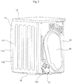
- FIG. 1 is a perspective view of a clothes dryer according to an embodiment of the present invention.
- FIG. 2 is a perspective view illustrating a rear side of the clothes dryer of FIG. 1 .
- FIG. 3 is a view illustrating main parts of a clothes dryer according to an embodiment of the present invention.
- the clothes dryer 1 according to an embodiment of the present invention will be described with reference to FIGS. 1 to 3 .
- a casing 10 forms an exterior of the clothes dryer 1.
- An introduction opening, through which clothes are introduced, may be formed on a front surface of the casing 10, and a door 21, which opens and closes the introduction opening, may be rotatably connected to the casing 10.
- the casing 10 may include a front panel 11, a right panel 12, a left panel (which is not shown, but is formed on an opposite side of the right panel 12), and a rear panel 16, which respectively form a front side, a left side, a right side, and a rear side of the clothes dryer.
- the casing 10 may further include a base 19 which is substantially horizontal and supports the panels, and a top plate 13 which is substantially horizontal and is connected to the top of the panels.
- the front panel 11 may include an upper panel 11a on which the introduction opening is formed, and a lower panel 11b which is disposed below the upper panel 11a.
- the door has an approximately circular shape, and is rotatably connected to the upper panel 11a, to open and close the introduction opening by operation of a user.
- a control panel 14 may be disposed above the front panel 11.
- the control panel 14 may include a display (e.g., LCD panel, LED panel, etc.) which displays an operating state of the clothes dryer, and an input part (e.g., button, dial, touch screen, etc.) which receives input of operation commands for operating the clothes dryer from a user.
- a display e.g., LCD panel, LED panel, etc.
- an input part e.g., button, dial, touch screen, etc.
- a water tank 15 may be provided at one side of the control panel 14 to be withdrawable therefrom. Condensed water generated during a drying process is collected in the water tank 15. A user may pull out the water tank 15 and may drain the condensed water collected therein.
- the casing 10 may include a ventilation part 161 which enables an inner space of the casing 10 to communicate with an external space.
- the ventilation part 161 may have at least one ventilation port.
- the ventilation part 161 may be provided at a rear surface (for example, at the rear panel 16) of the casing 10.
- the ventilation part 161 is formed in a grille shape having a plurality of slots 161h corresponding to the ventilation port, but is not limited thereto.
- the ventilation part 161 may be integrally formed with the casing 10. In the embodiment, the ventilation part 16 is integrally formed with the rear panel 16.
- a drum 31 may be rotatably disposed in the casing 10.
- a motor 52 may be disposed in the casing to rotate the drum 31.
- the drum 31 has a cylindrical shape with a front surface and a rear surface that are open, in which the open front surface communicates with the introduction opening formed at the front panel 11, and the open rear surface may be opened and closed by a supporter (not shown) which rotatably supports the drum 31.
- a lifter (not shown), which extends lengthwise in a longitudinal direction, may be disposed on an inner circumference of the drum 31.
- the lifter protrudes inward of the drum 31, and a plurality of lifters may be disposed at regular intervals along the circumference of the drum 31. During rotation of the drum 31, clothes are lifted and dropped repeatedly by the lifter.
- a belt 51 may be wound around an outer circumference of the drum 31.
- a pulley (not shown), with which the belt 51 is engaged, may be connected to a rotation axis of the motor 52.
- the method of rotating the drum 31 is not limited thereto.
- the drum 31 may have an open front surface and a closed rear surface, and the rotation axis may be connected to a rear surface of the drum 31 so that the rotation axis of the motor 52 and the center of rotation of the drum 31 may be arranged on the same line. This method is generally applied to a washer-dryer.
- a heater for heating air, and a blower fan 53 for blowing high-temperature air heated by the heater, may be provided in the casing 10. Further, a circulation flow path 40 for guiding circulation of an air flow after passing through the drum 31 may also be provided in the casing 10. The air blown by the blower fan 53 is transferred along the circulation flow path 40.
- a drying duct 45 is a part of the circulation flow path 40, and may be connected to the rear panel 16 of the casing 10. The air blown by the blower fan 53 is transferred through the drying duct 45 to be supplied into the drum 31.
- the clothes dryer 1 may include a heat pump 60.
- the heat pump 60 absorbs heat from air discharged from the drum 31 during circulation of refrigerant, and heats air supplied into the drum 31 by using the absorbed heat.
- the heat pump 60 may include an evaporator 62, a compressor 64, an expansion valve 65, and a condenser 63 which are connected by a refrigerant pipe 61, through which the refrigerant as a working fluid circulates.
- the evaporator 62 is a heat-exchanger including a fine-diameter tube connected with the refrigerant pipe 61, and heat-conductive heat-transfer plates for heat transfer between the tube and the heat-transfer plates.
- the evaporator 62 is provided on the circulation flow path 40 to absorb heat from the circulating air.
- the refrigerant is evaporated in such a manner that the evaporator 62 absorbs heat from an air flow discharged from the drum 31 (i.e., air discharged from the drum 31 after absorbing moisture from clothes in the drum 31), and the absorbed heat is transferred to the refrigerant in the tube.
- the moist air may be condensed while passing through the evaporator 62.
- a condensed water discharge device (not shown) for discharging condensed water from the circulation flow path 40 may be further included.
- the condensed water discharged by the condensed water discharge device may be collected in the water tank 15.
- the compressor 64 compresses the refrigerant after passing through the evaporator 62.
- the compressor 64 may be an inverter compressor, of which the number of revolutions (or compression capacity) may be changed, but is not limited thereto.
- the compression capacity of the inverter compressor may be varied by controlling the number of revolutions, such that a heating value of the condenser 63 may be controlled.
- the inverter compressor uses DC power as a power source. To this end, a driver (not shown), which converts AC power into DC power for conversion to a target frequency, may be further included.
- a cooling fan 54 for cooling the compressor 64 may be included in the casing 10.
- the cooling fan 54 may generate a suction force to suction outside air through the ventilation part 161.
- a controller (not shown) for controlling operation of the compressor 64 and the cooling fan 54, and a sensor (not shown) for sensing overheating of the compressor 64 may be provided.
- the sensor may be a temperature sensor which directly senses the temperature of the compressor 64, but is not limited thereto.
- the sensor may be a pressure sensor which senses discharge pressure of the compressor 64, in which case the controller determines overheating of the compressor 64 based on an output value of the pressure sensor. And upon determining that the compressor 64 is overheated, the controller may control the cooling fan 54 to operate.
- the condenser 63 may substantially have the same configuration as the evaporator 62, but serves to condense the refrigerant on the contrary to the evaporator 62. That is, the refrigerant compressed by the compressor 64 is condensed while passing through the condenser 63, and heat is released to the outside during this process.
- the condenser 63 is disposed downstream from the evaporator 62 on the circulation flow path 40.
- the air, of which humidity is lowered while passing through the evaporator 62, is then heated while passing through the condenser 63.
- the condenser 63 serves as a heater to heat the circulated air.
- a refrigerant circulation cycle is formed in such a manner that after the heat of the refrigerant is taken away by the circulating air while the refrigerant passes through the condenser 63, the refrigerant is expanded while passing through the expansion valve 65, and is introduced again into the evaporator 62.
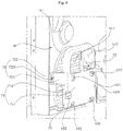
- FIG. 4 is an enlarged view illustrating a sound-insulating cover 70 connected to a casing 10.
- FIG. 5 is a view of a sound-insulating cover 70 and a sound-absorbing material 81.
- the clothes dryer 1 may include the sound-insulating cover 70 which is connected with the casing 10.
- the sound-insulating cover 70 may block noise, which is generated during the operation of the compressor 64 and the like, and is released to the outside through the ventilation slot 161h, thereby reducing noise.
- the sound-insulating cover 70 may be connected with the rear panel 16.
- description will be made based on an example where the ventilation part 161 is provided at the rear panel 16.
- the sound-insulating cover 70 includes a sound insulating plate 71.
- the sound insulating plate 71 is spaced apart from the ventilation part 161 so that air may be introduced into the casing 10 through the ventilation part 161.
- the sound-insulating plate 71 is disposed to overlap with at least a portion of the ventilation part 161. Since outside air may be introduced through a space between the sound-insulating plate 71 and the ventilation part 161, an amount of air flow introduced by the cooling fan 54 may be secured. That is, while securing the amount of air flow introduced through the ventilation slot 161h, the sound-insulating cover 70 may reduce noise released through the ventilation slot 161h.
- the sound-insulating cover 70 may further include a sound-insulating plate supporter 72 which extends from the sound-insulating plate 71 toward the casing 10 (e.g., the rear panel 16) to be connected with the casing 10 (e.g., the rear panel 16), so that the sound-insulating plate 71 may be fixed at a position spaced apart from the ventilation part 161.
- a sound-insulating plate supporter 72 which extends from the sound-insulating plate 71 toward the casing 10 (e.g., the rear panel 16) to be connected with the casing 10 (e.g., the rear panel 16), so that the sound-insulating plate 71 may be fixed at a position spaced apart from the ventilation part 161.
- the sound-insulating plate supporter 72 includes a supporting part 721 which extends from the sound-insulating plate 71, and a connection part 722 which is bent from the supporting part 721 to be disposed side by side with one surface of the casing 10 having the ventilation part 161.
- the connection part 722 may be connected with the casing 10 by a fastening member such as screws and bolts.
- the length of the supporting part 721 corresponds to a distance between the sound-insulating plate 71 and the casing 10, and accordingly, an amount of air flow introduced through a space between the sound-insulating plate 71 and the casing 10 is determined according to the length of the supporting part 721.
- connection part 722 may be bent from the supporting part 721 in a direction away from the ventilation part 161 (or laterally).
- the connection part 722 may be provided with a hole 722h, through which a fastening member coupled with the casing 10 may pass.
- a sound-absorbing material 81 may be further provided between the sound-insulating plate 71 and the ventilation part 161.
- the sound-absorbing member 81 may be made of a porous material, and may use synthetic resin as such material, but is not limited thereto.
- the sound-absorbing material 81 may be made of a compressible material capable of being deformed to some extent.
- the sound-insulating plate 71 may be provided with at least one air passage opening h11 and h12, through which outside air passes, in a region where the sound-insulating plate 71 overlaps with the ventilation part 161. It is desired that a total area, obtained by adding an outside air inlet area (i.e., an inlet area formed by a space between the sound-insulating plate 71 and the rear panel 16), which is formed between a periphery of the sound-insulating plate 71 and the casing 10, and an area of the at least one air passage opening h11 and h12, is equal to or more than twice an outside air inlet area formed by the ventilation part 161. That is, even when the sound-insulating cover 71 is mounted, a sufficient amount of air flow introduced through the ventilation part 161 may be secured, such that an effect on cooling performance of the compressor 64 may be reduced.
- an outside air inlet area i.e., an inlet area formed by a space between the sound-insulating plate 71 and the rear panel 16
- the air passage openings h11 and h12 are provided at a region that is not covered by the sound-absorbing material 81, and is desired to be formed above a region where the sound-absorbing material 81 is fixed.
- the sound-absorbing material 81 may be fixed below the air passage openings h11 and h12.
- the sound-insulating cover 70 may be provided with hooks HK21 and HK22 to fix the sound-absorbing material 81.
- the hooks HK21 and HK22 may include a horizontal part (HP) which extends horizontally from the sound-insulating plate 71 toward the ventilation part 161, and a vertical part (VP) which is bent from the horizontal part (HP) to extend downward.
- the sound-absorbing material 81 may be interposed between the vertical part (VP) and the sound-insulating plate 71. That is, the horizontal part (HP) extends to a length corresponding to a thickness of the sound-absorbing material 81, and may be fixed with the sound-absorbing material 81 being interposed between the vertical part (VP) and the sound-insulating plate 71.
- the sound-insulating plate 71 may have first through-holes h21 and h22.
- the position and shape of the first through-holes h21 and h22 may be configured in a manner that enables the entire vertical part VP of the hooks HK21 and HK22 to be viewed through the first through-holes h21 and h22.
- the sound-insulating cover 70 is integrally formed with the sound-insulating plate 71 by injection molding, the configuration allows the mold to be smoothly drawn out through the first through-holes h21 and h22, thereby enabling easy formation of the mold.
- the sound-insulating plate 71 may include a flat plate part 711 having one surface facing the ventilation part 161, and a side part 712 which is bent from a circumference of the flat plate part 711, and extends toward the ventilation part 161.
- the side part 712 may extend along the entire circumference of the sound-insulating plate 71.
- the sound-absorbing material 81 may be disposed in a concave space formed by the flat plate part 711 and the side part 712.
- the hooks HK21 and HK22 may be formed at the flat plate part 711.
- the sound-insulating cover 70 may further include at least one horizontal fixing tap HT23 and HT24 which protrudes from the side part 712 in a transverse direction.
- the sound-absorbing material 81 may be fixed between the horizontal fixing taps HT23 and HT24 and the flat plate part 711.
- the horizontal fixing taps HT23 and HT24 may be disposed below the hooks HK21 and HK22.
- a pair of horizontal fixing taps HT23 and HT24 is provided at portions forming a left side and a right side of the sound-insulating cover 70 on an outer circumference portion of the side part 712, and the pair of horizontal fixing taps HT23 and HT24 protrudes in a mutually facing direction.
- the sound-insulating cover 70 may have second through-holes h23 and h24 which are configured in a manner that enables the entire horizontal fixing taps HT23 and HT 24 to be viewed therethrough.
- the second through-holes h23 and h24 may not only secure an amount of air introduced through the ventilation part 161, but may also form a passage through which a mold is drawn out during injection molding of the horizontal fixing taps HT23 and HT24, in the same manner as the above-described first through-holes h21 and h22.
- the sound-insulating cover 70 may further include at least one vertical fixing tap VT25 (although not illustrated, the vertical fixing tap is also provided on a left portion of the sound-insulating cover 70 in FIG. 5 ), which protrudes upward from the side part 712.
- the sound-absorbing material 81 may be fixed between the vertical fixing tap VT25 and the flat plate part 711.
- the vertical fixing tap VT25 may be disposed below the horizontal fixing taps HT23 and HT24.
- a pair of vertical fixing taps VT25 is provided at a portion forming a bottom surface of the sound-insulating cover 70 on an outer circumference portion of the side part 712.
- the sound-insulating cover 70 may have third through-holes h25 and h26 which are configured in a manner that enables the entire vertical fixing taps VT25 to be viewed therethrough.
- the third through-holes h25 and h26 may not only secure an amount of air introduced through the ventilation part 161, but may also form a passage through which a mold is drawn out during injection molding of the vertical fixing tap VT25, in the same manner as the above-described first through-holes h21 and h22.
- FIG. 6 is a graph showing a noise amplitude (Y axis) relative to a noise frequency (X axis) measured while varying the number of revolutions of the compressor 64, and illustrating a comparison of a case (a) where the sound-insulating cover 70 and the sound-absorbing material 81 are not applied and a case (b) where the sound-insulating cover 70 and the sound-absorbing material 81 are applied.
- noise is reduced by approximately 0.4 dB to 2 dB in a high frequency range of 4000 hz or higher.
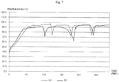
- FIG. 7 is a view illustrating a change in temperature of the compressor 64 according to time by comparing a case (a) where the sound-insulating cover 70 and the sound-absorbing material 81 are not applied and a case (b) where the sound-insulating cover 70 and the sound-absorbing material 81 are applied.
- the clothes dryer of the present invention has an effect of reducing the noise emanating through the ventilation slots.
Landscapes
- Engineering & Computer Science (AREA)
- Textile Engineering (AREA)
- Detail Structures Of Washing Machines And Dryers (AREA)
Applications Claiming Priority (1)
| Application Number | Priority Date | Filing Date | Title |
|---|---|---|---|
| KR1020160167931A KR102653163B1 (ko) | 2016-12-09 | 2016-12-09 | 의류 건조기 |
Publications (2)
| Publication Number | Publication Date |
|---|---|
| EP3333306A1 true EP3333306A1 (de) | 2018-06-13 |
| EP3333306B1 EP3333306B1 (de) | 2019-10-09 |
Family
ID=60627536
Family Applications (1)
| Application Number | Title | Priority Date | Filing Date |
|---|---|---|---|
| EP17205863.8A Active EP3333306B1 (de) | 2016-12-09 | 2017-12-07 | Wäschetrockner |
Country Status (3)
| Country | Link |
|---|---|
| US (1) | US10590592B2 (de) |
| EP (1) | EP3333306B1 (de) |
| KR (1) | KR102653163B1 (de) |
Cited By (2)
| Publication number | Priority date | Publication date | Assignee | Title |
|---|---|---|---|---|
| US20210345839A1 (en) * | 2017-09-29 | 2021-11-11 | Lg Electronics Inc. | Towel maintenance device |
| EP4092180A1 (de) * | 2021-04-27 | 2022-11-23 | Whirlpool Corporation | Isolierplatte für die rückwand eines wäschereigerätes |
Families Citing this family (9)
| Publication number | Priority date | Publication date | Assignee | Title |
|---|---|---|---|---|
| US10718082B2 (en) * | 2017-08-11 | 2020-07-21 | Whirlpool Corporation | Acoustic heat exchanger treatment for a laundry appliance having a heat pump system |
| DE102018212844A1 (de) * | 2018-08-01 | 2020-02-06 | BSH Hausgeräte GmbH | Haushaltsgerät mit verbesserter Akustik |
| EP3998381A4 (de) * | 2019-07-12 | 2023-04-19 | LG Electronics Inc. | Trockner |
| WO2022182127A1 (en) * | 2021-02-24 | 2022-09-01 | Lg Electronics Inc. | Laundry treating apparatus |
| CN116536895A (zh) * | 2022-01-25 | 2023-08-04 | 青岛海尔洗涤电器有限公司 | 烘干设备 |
| US12366030B2 (en) | 2022-07-06 | 2025-07-22 | Whirlpool Corporation | Laundry machine |
| US20240093421A1 (en) * | 2022-09-16 | 2024-03-21 | Whirlpool Corporation | Laundry machine |
| JP1824972S (ja) * | 2022-12-08 | 2026-04-21 | 衣服用乾燥機 | |
| USD1111270S1 (en) * | 2022-12-08 | 2026-02-03 | Lg Electronics Inc. | Dryer for clothing |
Citations (4)
| Publication number | Priority date | Publication date | Assignee | Title |
|---|---|---|---|---|
| EP1865103A1 (de) * | 2006-06-06 | 2007-12-12 | Electrolux Home Products Corporation N.V. | Wäschetrockner mit Schallabsorptionssystem |
| US20090260248A1 (en) * | 2008-04-18 | 2009-10-22 | Mabe Canada Inc. | Clothes dryer with thermal insulation pad |
| EP2199454A2 (de) * | 2008-12-22 | 2010-06-23 | BSH Bosch und Siemens Hausgeräte GmbH | Hausgerät mit einem offenen Luftkanal |
| WO2014154251A1 (en) * | 2013-03-26 | 2014-10-02 | Arcelik Anonim Sirketi | Heat pump laundry dryer with noise attenuation structure |
Family Cites Families (2)
| Publication number | Priority date | Publication date | Assignee | Title |
|---|---|---|---|---|
| JP3676901B2 (ja) * | 1997-03-21 | 2005-07-27 | 三菱電機株式会社 | 冷蔵庫の製造方法及び冷蔵庫 |
| KR100595760B1 (ko) * | 2004-12-06 | 2006-06-30 | 엘지전자 주식회사 | 증기압축 사이클 시스템을 구비하는 의류 건조기 |
-
2016
- 2016-12-09 KR KR1020160167931A patent/KR102653163B1/ko active Active
-
2017
- 2017-12-07 EP EP17205863.8A patent/EP3333306B1/de active Active
- 2017-12-08 US US15/835,730 patent/US10590592B2/en active Active
Patent Citations (4)
| Publication number | Priority date | Publication date | Assignee | Title |
|---|---|---|---|---|
| EP1865103A1 (de) * | 2006-06-06 | 2007-12-12 | Electrolux Home Products Corporation N.V. | Wäschetrockner mit Schallabsorptionssystem |
| US20090260248A1 (en) * | 2008-04-18 | 2009-10-22 | Mabe Canada Inc. | Clothes dryer with thermal insulation pad |
| EP2199454A2 (de) * | 2008-12-22 | 2010-06-23 | BSH Bosch und Siemens Hausgeräte GmbH | Hausgerät mit einem offenen Luftkanal |
| WO2014154251A1 (en) * | 2013-03-26 | 2014-10-02 | Arcelik Anonim Sirketi | Heat pump laundry dryer with noise attenuation structure |
Cited By (4)
| Publication number | Priority date | Publication date | Assignee | Title |
|---|---|---|---|---|
| US20210345839A1 (en) * | 2017-09-29 | 2021-11-11 | Lg Electronics Inc. | Towel maintenance device |
| US11647873B2 (en) * | 2017-09-29 | 2023-05-16 | Lg Electronics Inc. | Towel maintenance device |
| EP4092180A1 (de) * | 2021-04-27 | 2022-11-23 | Whirlpool Corporation | Isolierplatte für die rückwand eines wäschereigerätes |
| US12203208B2 (en) | 2021-04-27 | 2025-01-21 | Whirlpool Corporation | Insulation panel for back panel of laundry appliance |
Also Published As
| Publication number | Publication date |
|---|---|
| US10590592B2 (en) | 2020-03-17 |
| US20180163340A1 (en) | 2018-06-14 |
| KR20180066742A (ko) | 2018-06-19 |
| KR102653163B1 (ko) | 2024-04-01 |
| EP3333306B1 (de) | 2019-10-09 |
Similar Documents
| Publication | Publication Date | Title |
|---|---|---|
| EP3333306B1 (de) | Wäschetrockner | |
| JP6882385B2 (ja) | 乾燥機 | |
| EP2787117B1 (de) | Kleidungstrockner | |
| KR100782377B1 (ko) | 의류 건조 및 보관 장치 | |
| KR102891197B1 (ko) | 의류 관리기 및 그 제어 방법 | |
| US8667702B2 (en) | Domestic appliance with an open air duct | |
| EP3015591B1 (de) | Kleiderbehandlungsvorrichtung und steuerungsverfahren dafür | |
| CN105051281B (zh) | 洗衣机及其控制方法 | |
| US20120049705A1 (en) | Laundry Treating Machine with Bottom-Side Air Passage | |
| CN117203477B (zh) | 用于运行空调器单元的变速压缩机的系统和方法 | |
| TW201135003A (en) | Washing-drying machine and drying machine | |
| CN102560989B (zh) | 干燥机及洗涤干燥机 | |
| KR20200075667A (ko) | 의류처리장치 및 의류처리장치의 제어 방법 | |
| KR20200009768A (ko) | 냉풍 및 열풍 건조시스템 | |
| JP7319028B2 (ja) | 衣類乾燥機 | |
| KR20210007703A (ko) | 건조기 | |
| CN101676471A (zh) | 干燥机及洗涤干燥机 | |
| CN111254642A (zh) | 用于衣物护理设备的控制方法及衣物护理设备 | |
| CN117203472B (zh) | 用于运行空调器单元的变速压缩机的系统和方法 | |
| KR20190128529A (ko) | 의류 처리 장치 | |
| CN101403180B (zh) | 干燥机及洗涤干燥机 | |
| CN107543251B (zh) | 室内机 | |
| KR20190087004A (ko) | 건조기 | |
| CN101424035B (zh) | 干燥机及洗涤干燥机 | |
| KR20230095422A (ko) | 의류 건조기 및 결빙 방지 구동 방법 |
Legal Events
| Date | Code | Title | Description |
|---|---|---|---|
| PUAI | Public reference made under article 153(3) epc to a published international application that has entered the european phase |
Free format text: ORIGINAL CODE: 0009012 |
|
| STAA | Information on the status of an ep patent application or granted ep patent |
Free format text: STATUS: REQUEST FOR EXAMINATION WAS MADE |
|
| 17P | Request for examination filed |
Effective date: 20180108 |
|
| AK | Designated contracting states |
Kind code of ref document: A1 Designated state(s): AL AT BE BG CH CY CZ DE DK EE ES FI FR GB GR HR HU IE IS IT LI LT LU LV MC MK MT NL NO PL PT RO RS SE SI SK SM TR |
|
| AX | Request for extension of the european patent |
Extension state: BA ME |
|
| RBV | Designated contracting states (corrected) |
Designated state(s): AL AT BE BG CH CY CZ DE DK EE ES FI FR GB GR HR HU IE IS IT LI LT LU LV MC MK MT NL NO PL PT RO RS SE SI SK SM TR |
|
| GRAP | Despatch of communication of intention to grant a patent |
Free format text: ORIGINAL CODE: EPIDOSNIGR1 |
|
| STAA | Information on the status of an ep patent application or granted ep patent |
Free format text: STATUS: GRANT OF PATENT IS INTENDED |
|
| RIC1 | Information provided on ipc code assigned before grant |
Ipc: D06F 39/12 20060101ALN20190307BHEP Ipc: D06F 58/20 20060101AFI20190307BHEP |
|
| INTG | Intention to grant announced |
Effective date: 20190328 |
|
| GRAJ | Information related to disapproval of communication of intention to grant by the applicant or resumption of examination proceedings by the epo deleted |
Free format text: ORIGINAL CODE: EPIDOSDIGR1 |
|
| STAA | Information on the status of an ep patent application or granted ep patent |
Free format text: STATUS: REQUEST FOR EXAMINATION WAS MADE |
|
| GRAR | Information related to intention to grant a patent recorded |
Free format text: ORIGINAL CODE: EPIDOSNIGR71 |
|
| GRAS | Grant fee paid |
Free format text: ORIGINAL CODE: EPIDOSNIGR3 |
|
| STAA | Information on the status of an ep patent application or granted ep patent |
Free format text: STATUS: GRANT OF PATENT IS INTENDED |
|
| GRAA | (expected) grant |
Free format text: ORIGINAL CODE: 0009210 |
|
| STAA | Information on the status of an ep patent application or granted ep patent |
Free format text: STATUS: THE PATENT HAS BEEN GRANTED |
|
| INTC | Intention to grant announced (deleted) | ||
| RIC1 | Information provided on ipc code assigned before grant |
Ipc: D06F 58/20 20060101AFI20190806BHEP Ipc: D06F 39/12 20060101ALN20190806BHEP |
|
| AK | Designated contracting states |
Kind code of ref document: B1 Designated state(s): AL AT BE BG CH CY CZ DE DK EE ES FI FR GB GR HR HU IE IS IT LI LT LU LV MC MK MT NL NO PL PT RO RS SE SI SK SM TR |
|
| INTG | Intention to grant announced |
Effective date: 20190902 |
|
| REG | Reference to a national code |
Ref country code: GB Ref legal event code: FG4D |
|
| REG | Reference to a national code |
Ref country code: CH Ref legal event code: EP |
|
| REG | Reference to a national code |
Ref country code: IE Ref legal event code: FG4D |
|
| REG | Reference to a national code |
Ref country code: DE Ref legal event code: R096 Ref document number: 602017007661 Country of ref document: DE |
|
| REG | Reference to a national code |
Ref country code: AT Ref legal event code: REF Ref document number: 1188942 Country of ref document: AT Kind code of ref document: T Effective date: 20191115 |
|
| REG | Reference to a national code |
Ref country code: NL Ref legal event code: MP Effective date: 20191009 |
|
| REG | Reference to a national code |
Ref country code: LT Ref legal event code: MG4D |
|
| REG | Reference to a national code |
Ref country code: AT Ref legal event code: MK05 Ref document number: 1188942 Country of ref document: AT Kind code of ref document: T Effective date: 20191009 |
|
| PG25 | Lapsed in a contracting state [announced via postgrant information from national office to epo] |
Ref country code: GR Free format text: LAPSE BECAUSE OF FAILURE TO SUBMIT A TRANSLATION OF THE DESCRIPTION OR TO PAY THE FEE WITHIN THE PRESCRIBED TIME-LIMIT Effective date: 20200110 Ref country code: PT Free format text: LAPSE BECAUSE OF FAILURE TO SUBMIT A TRANSLATION OF THE DESCRIPTION OR TO PAY THE FEE WITHIN THE PRESCRIBED TIME-LIMIT Effective date: 20200210 Ref country code: ES Free format text: LAPSE BECAUSE OF FAILURE TO SUBMIT A TRANSLATION OF THE DESCRIPTION OR TO PAY THE FEE WITHIN THE PRESCRIBED TIME-LIMIT Effective date: 20191009 Ref country code: LT Free format text: LAPSE BECAUSE OF FAILURE TO SUBMIT A TRANSLATION OF THE DESCRIPTION OR TO PAY THE FEE WITHIN THE PRESCRIBED TIME-LIMIT Effective date: 20191009 Ref country code: NL Free format text: LAPSE BECAUSE OF FAILURE TO SUBMIT A TRANSLATION OF THE DESCRIPTION OR TO PAY THE FEE WITHIN THE PRESCRIBED TIME-LIMIT Effective date: 20191009 Ref country code: PL Free format text: LAPSE BECAUSE OF FAILURE TO SUBMIT A TRANSLATION OF THE DESCRIPTION OR TO PAY THE FEE WITHIN THE PRESCRIBED TIME-LIMIT Effective date: 20191009 Ref country code: SE Free format text: LAPSE BECAUSE OF FAILURE TO SUBMIT A TRANSLATION OF THE DESCRIPTION OR TO PAY THE FEE WITHIN THE PRESCRIBED TIME-LIMIT Effective date: 20191009 Ref country code: LV Free format text: LAPSE BECAUSE OF FAILURE TO SUBMIT A TRANSLATION OF THE DESCRIPTION OR TO PAY THE FEE WITHIN THE PRESCRIBED TIME-LIMIT Effective date: 20191009 Ref country code: AT Free format text: LAPSE BECAUSE OF FAILURE TO SUBMIT A TRANSLATION OF THE DESCRIPTION OR TO PAY THE FEE WITHIN THE PRESCRIBED TIME-LIMIT Effective date: 20191009 Ref country code: NO Free format text: LAPSE BECAUSE OF FAILURE TO SUBMIT A TRANSLATION OF THE DESCRIPTION OR TO PAY THE FEE WITHIN THE PRESCRIBED TIME-LIMIT Effective date: 20200109 Ref country code: BG Free format text: LAPSE BECAUSE OF FAILURE TO SUBMIT A TRANSLATION OF THE DESCRIPTION OR TO PAY THE FEE WITHIN THE PRESCRIBED TIME-LIMIT Effective date: 20200109 Ref country code: FI Free format text: LAPSE BECAUSE OF FAILURE TO SUBMIT A TRANSLATION OF THE DESCRIPTION OR TO PAY THE FEE WITHIN THE PRESCRIBED TIME-LIMIT Effective date: 20191009 |
|
| PG25 | Lapsed in a contracting state [announced via postgrant information from national office to epo] |
Ref country code: RS Free format text: LAPSE BECAUSE OF FAILURE TO SUBMIT A TRANSLATION OF THE DESCRIPTION OR TO PAY THE FEE WITHIN THE PRESCRIBED TIME-LIMIT Effective date: 20191009 Ref country code: IS Free format text: LAPSE BECAUSE OF FAILURE TO SUBMIT A TRANSLATION OF THE DESCRIPTION OR TO PAY THE FEE WITHIN THE PRESCRIBED TIME-LIMIT Effective date: 20200224 Ref country code: HR Free format text: LAPSE BECAUSE OF FAILURE TO SUBMIT A TRANSLATION OF THE DESCRIPTION OR TO PAY THE FEE WITHIN THE PRESCRIBED TIME-LIMIT Effective date: 20191009 |
|
| PG25 | Lapsed in a contracting state [announced via postgrant information from national office to epo] |
Ref country code: AL Free format text: LAPSE BECAUSE OF FAILURE TO SUBMIT A TRANSLATION OF THE DESCRIPTION OR TO PAY THE FEE WITHIN THE PRESCRIBED TIME-LIMIT Effective date: 20191009 |
|
| REG | Reference to a national code |
Ref country code: DE Ref legal event code: R097 Ref document number: 602017007661 Country of ref document: DE |
|
| PG2D | Information on lapse in contracting state deleted |
Ref country code: IS |
|
| PG25 | Lapsed in a contracting state [announced via postgrant information from national office to epo] |
Ref country code: EE Free format text: LAPSE BECAUSE OF FAILURE TO SUBMIT A TRANSLATION OF THE DESCRIPTION OR TO PAY THE FEE WITHIN THE PRESCRIBED TIME-LIMIT Effective date: 20191009 Ref country code: DK Free format text: LAPSE BECAUSE OF FAILURE TO SUBMIT A TRANSLATION OF THE DESCRIPTION OR TO PAY THE FEE WITHIN THE PRESCRIBED TIME-LIMIT Effective date: 20191009 Ref country code: CZ Free format text: LAPSE BECAUSE OF FAILURE TO SUBMIT A TRANSLATION OF THE DESCRIPTION OR TO PAY THE FEE WITHIN THE PRESCRIBED TIME-LIMIT Effective date: 20191009 Ref country code: RO Free format text: LAPSE BECAUSE OF FAILURE TO SUBMIT A TRANSLATION OF THE DESCRIPTION OR TO PAY THE FEE WITHIN THE PRESCRIBED TIME-LIMIT Effective date: 20191009 Ref country code: IS Free format text: LAPSE BECAUSE OF FAILURE TO SUBMIT A TRANSLATION OF THE DESCRIPTION OR TO PAY THE FEE WITHIN THE PRESCRIBED TIME-LIMIT Effective date: 20200209 |
|
| PLBE | No opposition filed within time limit |
Free format text: ORIGINAL CODE: 0009261 |
|
| STAA | Information on the status of an ep patent application or granted ep patent |
Free format text: STATUS: NO OPPOSITION FILED WITHIN TIME LIMIT |
|
| REG | Reference to a national code |
Ref country code: BE Ref legal event code: MM Effective date: 20191231 |
|
| PG25 | Lapsed in a contracting state [announced via postgrant information from national office to epo] |
Ref country code: SM Free format text: LAPSE BECAUSE OF FAILURE TO SUBMIT A TRANSLATION OF THE DESCRIPTION OR TO PAY THE FEE WITHIN THE PRESCRIBED TIME-LIMIT Effective date: 20191009 Ref country code: MC Free format text: LAPSE BECAUSE OF FAILURE TO SUBMIT A TRANSLATION OF THE DESCRIPTION OR TO PAY THE FEE WITHIN THE PRESCRIBED TIME-LIMIT Effective date: 20191009 Ref country code: SK Free format text: LAPSE BECAUSE OF FAILURE TO SUBMIT A TRANSLATION OF THE DESCRIPTION OR TO PAY THE FEE WITHIN THE PRESCRIBED TIME-LIMIT Effective date: 20191009 Ref country code: IT Free format text: LAPSE BECAUSE OF FAILURE TO SUBMIT A TRANSLATION OF THE DESCRIPTION OR TO PAY THE FEE WITHIN THE PRESCRIBED TIME-LIMIT Effective date: 20191009 |
|
| 26N | No opposition filed |
Effective date: 20200710 |
|
| PG25 | Lapsed in a contracting state [announced via postgrant information from national office to epo] |
Ref country code: IE Free format text: LAPSE BECAUSE OF NON-PAYMENT OF DUE FEES Effective date: 20191207 Ref country code: FR Free format text: LAPSE BECAUSE OF NON-PAYMENT OF DUE FEES Effective date: 20191209 Ref country code: LU Free format text: LAPSE BECAUSE OF NON-PAYMENT OF DUE FEES Effective date: 20191207 |
|
| PG25 | Lapsed in a contracting state [announced via postgrant information from national office to epo] |
Ref country code: SI Free format text: LAPSE BECAUSE OF FAILURE TO SUBMIT A TRANSLATION OF THE DESCRIPTION OR TO PAY THE FEE WITHIN THE PRESCRIBED TIME-LIMIT Effective date: 20191009 Ref country code: BE Free format text: LAPSE BECAUSE OF NON-PAYMENT OF DUE FEES Effective date: 20191231 |
|
| PG25 | Lapsed in a contracting state [announced via postgrant information from national office to epo] |
Ref country code: CY Free format text: LAPSE BECAUSE OF FAILURE TO SUBMIT A TRANSLATION OF THE DESCRIPTION OR TO PAY THE FEE WITHIN THE PRESCRIBED TIME-LIMIT Effective date: 20191009 |
|
| PG25 | Lapsed in a contracting state [announced via postgrant information from national office to epo] |
Ref country code: HU Free format text: LAPSE BECAUSE OF FAILURE TO SUBMIT A TRANSLATION OF THE DESCRIPTION OR TO PAY THE FEE WITHIN THE PRESCRIBED TIME-LIMIT; INVALID AB INITIO Effective date: 20171207 Ref country code: MT Free format text: LAPSE BECAUSE OF FAILURE TO SUBMIT A TRANSLATION OF THE DESCRIPTION OR TO PAY THE FEE WITHIN THE PRESCRIBED TIME-LIMIT Effective date: 20191009 |
|
| REG | Reference to a national code |
Ref country code: CH Ref legal event code: PL |
|
| PG25 | Lapsed in a contracting state [announced via postgrant information from national office to epo] |
Ref country code: LI Free format text: LAPSE BECAUSE OF NON-PAYMENT OF DUE FEES Effective date: 20201231 Ref country code: CH Free format text: LAPSE BECAUSE OF NON-PAYMENT OF DUE FEES Effective date: 20201231 |
|
| PG25 | Lapsed in a contracting state [announced via postgrant information from national office to epo] |
Ref country code: TR Free format text: LAPSE BECAUSE OF FAILURE TO SUBMIT A TRANSLATION OF THE DESCRIPTION OR TO PAY THE FEE WITHIN THE PRESCRIBED TIME-LIMIT Effective date: 20191009 |
|
| PG25 | Lapsed in a contracting state [announced via postgrant information from national office to epo] |
Ref country code: MK Free format text: LAPSE BECAUSE OF FAILURE TO SUBMIT A TRANSLATION OF THE DESCRIPTION OR TO PAY THE FEE WITHIN THE PRESCRIBED TIME-LIMIT Effective date: 20191009 |
|
| GBPC | Gb: european patent ceased through non-payment of renewal fee |
Effective date: 20211207 |
|
| PG25 | Lapsed in a contracting state [announced via postgrant information from national office to epo] |
Ref country code: GB Free format text: LAPSE BECAUSE OF NON-PAYMENT OF DUE FEES Effective date: 20211207 |
|
| PGFP | Annual fee paid to national office [announced via postgrant information from national office to epo] |
Ref country code: DE Payment date: 20251105 Year of fee payment: 9 |