EP3330580A1 - Verwendung eines beschichteten o-rings für eine gas-isolierte elektrische ausrüstung - Google Patents
Verwendung eines beschichteten o-rings für eine gas-isolierte elektrische ausrüstung Download PDFInfo
- Publication number
- EP3330580A1 EP3330580A1 EP16460091.8A EP16460091A EP3330580A1 EP 3330580 A1 EP3330580 A1 EP 3330580A1 EP 16460091 A EP16460091 A EP 16460091A EP 3330580 A1 EP3330580 A1 EP 3330580A1
- Authority
- EP
- European Patent Office
- Prior art keywords
- gas
- seal
- ring
- electric apparatus
- core ring
- Prior art date
- Legal status (The legal status is an assumption and is not a legal conclusion. Google has not performed a legal analysis and makes no representation as to the accuracy of the status listed.)
- Withdrawn
Links
Images


Classifications
-
- F—MECHANICAL ENGINEERING; LIGHTING; HEATING; WEAPONS; BLASTING
- F16—ENGINEERING ELEMENTS AND UNITS; GENERAL MEASURES FOR PRODUCING AND MAINTAINING EFFECTIVE FUNCTIONING OF MACHINES OR INSTALLATIONS; THERMAL INSULATION IN GENERAL
- F16J—PISTONS; CYLINDERS; SEALINGS
- F16J15/00—Sealings
- F16J15/02—Sealings between relatively-stationary surfaces
- F16J15/06—Sealings between relatively-stationary surfaces with solid packing compressed between sealing surfaces
- F16J15/10—Sealings between relatively-stationary surfaces with solid packing compressed between sealing surfaces with non-metallic packing
- F16J15/104—Sealings between relatively-stationary surfaces with solid packing compressed between sealing surfaces with non-metallic packing characterised by structure
-
- F—MECHANICAL ENGINEERING; LIGHTING; HEATING; WEAPONS; BLASTING
- F16—ENGINEERING ELEMENTS AND UNITS; GENERAL MEASURES FOR PRODUCING AND MAINTAINING EFFECTIVE FUNCTIONING OF MACHINES OR INSTALLATIONS; THERMAL INSULATION IN GENERAL
- F16J—PISTONS; CYLINDERS; SEALINGS
- F16J15/00—Sealings
- F16J15/02—Sealings between relatively-stationary surfaces
- F16J15/06—Sealings between relatively-stationary surfaces with solid packing compressed between sealing surfaces
- F16J15/10—Sealings between relatively-stationary surfaces with solid packing compressed between sealing surfaces with non-metallic packing
- F16J15/12—Sealings between relatively-stationary surfaces with solid packing compressed between sealing surfaces with non-metallic packing with metal reinforcement or covering
- F16J15/128—Sealings between relatively-stationary surfaces with solid packing compressed between sealing surfaces with non-metallic packing with metal reinforcement or covering with metal covering
-
- H—ELECTRICITY
- H02—GENERATION; CONVERSION OR DISTRIBUTION OF ELECTRIC POWER
- H02G—INSTALLATION OF ELECTRIC CABLES OR LINES, OR OF COMBINED OPTICAL AND ELECTRIC CABLES OR LINES
- H02G5/00—Installations of bus-bars
- H02G5/06—Totally-enclosed installations, e.g. in metal casings
- H02G5/066—Devices for maintaining distance between conductor and enclosure
- H02G5/068—Devices for maintaining distance between conductor and enclosure being part of the junction between two enclosures
Definitions
- the invention relates to an insulation assembly for gas-insulated electric apparatus and a specially to the insulation assembly which is constructed as an insulator body inserted between connecting flanges of the gas -insulated switching installation where the flanges are closed by an outer metal ring.
- Gas insulated electrical apparatus like switchgears - high and medium voltage, circuit breakers, life tank breakers etc. are filled with insulating gases.
- the supporting insulator has an insulator body inserted between connecting flanges of the gas -insulated switching installation (vessels) where the flanges are closed by an outer metal ring.
- a sealing system is used for keeping the insulating gas inside the switching installation.
- an O-ring seal is used. These O-ring seal is placed on a collar made on an external surface of the insulating body between an internal surface of the connecting flange and between an internal side of the outer ring.
- the sealing systems like O-ring seals or gaskets, usually are made of different types of rubber like EPDM (Ethylene Propylene Diene), NBR (Nitrile Butadiene Rubber), FKM (Fluoroelastomer), IIR (Isobutylene Isoprene Rubber).
- EPDM Ethylene Propylene Diene
- NBR Nirile Butadiene Rubber
- FKM Feluoroelastomer
- IIR Isobutylene Isoprene Rubber
- gas seal in an insulation assembly for gas-insulated electric apparatus, where the insulation assembly comprises an insulator body placed axially round axis X-X on a current- carrying conductor in an insulating chamber, between the connecting flanges and an outer metal ring, closing the insulation chamber filled with a gas insulating medium, or where the assembly comprises a cover placed axially round axis Y-Y in an insulating chamber filled with a gas insulating medium, the said use is characterized in that the gas seal has an O-ring or X-ring type shape and consists of seal core ring covered with at least one layer of a coating. The seal core ring is made from different material than the coating.
- gas seal of an insulation assembly for gas-insulated electric apparatus characterized in that the coating is arranged on the two faces of the seal core ring in a way that one face of the seal core ring is covered by a different coating that the other coating placed on the other face of the seal core ring.
- gas seal of an insulation assembly for gas-insulated electric apparatus characterized in that the seal core ring is made from material having a coefficient of gas permeability P lower than 2.0*10 -16 expressed in mole meters per square meters second pascal [mol*m/(m 2 *s*Pa)] for carbon dioxide CO2 and 0.8*10 -18 expressed in mole meters per square meters second pascal [mol*m/(m 2 *s*Pa)] for sulfur hexafluoride SF6 gas.
- gas seal of an insulation assembly for gas-insulated electric apparatus characterized in that the seal core ring is made from metal, metal alloy or a polymer.
- gas seal of an insulation assembly for gas-insulated electric apparatus characterized in that the coating is made from metal, rubber or thermoplastic elastomer.
- An insulation assembly for gas-insulated electric apparatus comprises an insulator body placed axially on a current- carrying conductor inside an insulating chamber filled with insulating medium, having an outer metal ring placed between the connecting flanges of the electric apparatus closing the insulating chamber; equipped with a gas seal placed between one of the internal surfaces of the flanges and the external collar surface of the insulator body and a part of the internal surface of the outer metal ring, characterized in that the gas seal has a form of a seal core ring which is covered with at least one layer of a coating made from different material that for the seal core ring.
- An insulation assembly for gas-insulated electric apparatus comprises an insulator body placed axially on a current- carrying conductor inside an insulating chamber filled with insulating medium, having an outer metal ring placed between the connecting flanges of the electric apparatus closing the insulating chamber; equipped with a gas seal placed between one of the internal surfaces of the flanges, and the external surfaces of the insulating body between the two collars of the insulator body, characterized in that the gas seal has a form of a seal core ring which is covered with at least one layer of a coating made from different material that for the seal core ring.
- An insulation assembly for gas-insulated electric apparatus comprises a cover covering the flange and closing the chamber filled with insulating medium, equipped with a gas seal which is placed in a grove formed in the internal surface of the cover, characterized in that the gas seal has a form of a seal core ring which is covered with at least one layer of a coating made from different material that for the seal core ring.
- the insulation assembly for gas-insulated electric apparatus characterized in that the seal core ring is made from material having a coefficient of gas permeability P lower than 2.0*10 -16 expressed in mole meters per square meters second pascal [mol*m/(m 2 *s*Pa)] for carbon dioxide CO2 and 0.8*10 -18 expressed in mole meters per square meters second pascal [mol*m/(m 2 *s*Pa)] for sulfur hexafluoride SF6 gas.
- the insulation assembly for gas-insulated electric apparatus characterized in that the seal core ring is made from metal, metal alloy or a polymer.
- the insulation assembly for gas-insulated electric apparatus characterized in that the seal core ring has two kinds of coatings made from different material and placed on different faces of the seal core ring.
- the insulation assembly for gas-insulated electric apparatus characterized in that that the coatings are made from metal, rubber, thermoplastic elastomer.
- gas seal allows for decreasing the leakage of the dielectric gas from the insulation chamber by utilization of core sealing material with very low permeation coefficient which decrease leakage due to permeation.
- core sealing material with very low permeation coefficient which decrease leakage due to permeation.
- the seal core can have one or two coatings made of elastic material like rubber or plastic material like metal. Elastomeric materials are used as a coating for their good interface sealing ability and multiple use possibility due to elastic property. Metals like tin or copper are used as a coating to minimize leakage due to permeation.
- the sealing at the interface is achieved due to material plasticity so it can only be used for sealing surfaces made of materials harder that the coating material.
- Application of two different coating materials allow to minimize gas leakage by optimal choice of coating material adapted to the properties of sealed surfaces.
- An insulation assembly 1 for switching installation for example GIS ( Gas Insulated Switchgear) comprises an insulator body 2 in the form of disk placed axially round axis X-X on a current carrying conductor 3.
- the insulator body is made from epoxy resin or other thermosetting or thermoplastic material.
- the insulator body 2 is placed in an insulating chamber 4 between the flanges 5 and 6 of the switching installation and axially inside the outer metal ring 7, closing the insulation chamber 4 filled with insulating medium 8.
- the insulation medium 8 could be one of insulating gases like sulfur hexafluoride SF 6 , carbon dioxide CO2 or different gas mixtures based on fluoroketones like 1,1,1,3,4,4,4-heptafluoro-3-(trifluoromethyl)butan-2 (C5 FK). Between the internal surfaces 5a and 6a of the flanges 5,6 respectively, and external faces 2a of the insulator body 2 two gas seals 9 are inserted, radially to the conductor 3.
- the gas seal 9 has a form of a ring 9a covered entirely or partially with at least one layer of a coating 9b.
- the seal ring 9a has such properties that it is made of material characterized by an extremely low coefficient of gas permeability P, lower than 2.0*10 -16 expressed in mole meters per square meters second pascal [mol*m/(m 2 *s*Pa)] for carbon dioxide CO2 and 0.8*10 -18 expressed in mole meters per square meters second pascal [mol*m/(m 2 *s*Pa)] for sulfur hexafluoride SF6 gas.
- the coefficient of gas permeability P is presented in the Svensk Standard SS-ISO 15105-1:2009, "Plastics - Film and sheeting-Determination of gas-transmission rate - Part 1: Differential -pressure methods (ISO 15105-1:2007, IDT”.
- the seal core ring 9 is made from metal, metal alloy or a polymer.
- the coating 9b can be made of different materials depending on structure and material of interacting surfaces.
- the coating 9b has such properties that it is made of soft material characterized by plasticity or elasticity assuring good gas sealing at the interface with either or both metal surface of flange (5a, 5b) and the of insulating body (2a).
- the coating material can be soft metal, rubber, thermoplastic elastomer or similar.
- the flanges 5 and 6 and the outer metal ring 7 are held together by a clamping bolt 10, and clamping nuts 11, closing the insulation chamber 4 round axis x-x.
- An exemplary gas seal 9 is carried out with a copper core 9a and a silver coating 9b.
- the coating 9b is the same for the both sides of the ring 9a or is different for the both sides, for example on one face side is a coating 9b' and on the other side id a coating 9b".
- the difference in the coating material on the both face side of the seal ring allows for choosing the best condition of the sealing the flange 5 or 6, made from metal and the insulator body 2, made from resin or other thermosetting or thermoplastic material.
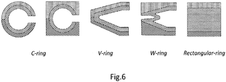
- the shape of the gas seal 9 could be different as O-ring and be general described as X- ring, where X stands for any shape which fits into existing insulator body, such as C-ring, V-ring, W-ring or Rectangular-ring schematically illustrated on fig.5 .
- the use of gas seal 9 is arranged in the space between the collar 2a, the end of insulator body 2, the internal surface 7a of the metal ring 7 and the internal surface 5a of the flange 5 or the internal surface 6a of the flange 6.
- the gas seal 9 is in contact with at least one internal surface 5a, 6a of the flange 5,6, respectively, and with the external surface of the collar 2a on the end of the insulator body in such a way that it is possible to choose the different coating 9b' or 9b" for contacting with the different material of flanges 5 or 6 and insulator body 2.
- the selection of the material depends on material and surface characteristics, for example roughness, hardness, thermal expansion coefficient of the insulator body 2 or flanges 5,6.
- the use of gas seal 9 is arranged in a grove formed by the collar 2a and 2b.
- the gas seal 9 is arranged in a space limited by the external surface of the groove between the collars 2a and 2b of the insulator body and one of the internal surface 5a of the flange 5 or the surface 6a of the flange 6.
- the seal 9 is in contact with the surface of the insulation body and the internal surface of the flange 5 or 6 in such a way that it is possible to chose the different coating 9b' or 9b" what is depended on material and surface characteristics (roughness, hardness, thermal expansion coefficient) of insulator body 2 or flanges 5,6.
- the use of gas seal 9 is placed in a grove 13 formed in the internal surface of the cover 12.
- the cover 12 is fixed to the flange 5' through the clamping bolt 10, and clamping nuts 11, closing the insulation chamber 4'.
- the grove 13 is situated around the edge of the cover 12 and in a distance from the axis Y-Y less than the distance from the axis Y-Y of the arrangement of the clamping bolt axis y-y.
- the gas seal 9 is made from at least two different materials one for the core ring 9a ant the other for the coating 9b.
- the seal ring 9a is made of material characterized by an extremely low coefficient of gas permeability P, lower than 2.0*10 -16 expressed in mole meters per square meters second pascal [mol*m/(m 2 *s*Pa)] for carbon dioxide CO2 and 0.8*10 -18 expressed in mole meters per square meters second pascal [mol*m/(m 2 *s*Pa)] for sulfur hexafluoride SF6 gas.
- the coating material is chosen from metal, rubber, thermoplastic elastomer.
- the shape of the gas seal 9 could be different as O-ring and be general described as X- ring, where X stands for any shape which fits into existing insulator body, such as C-ring, V-ring, W-ring or Rectangular-ring schematically illustrated on fig.5 .
Landscapes
- Engineering & Computer Science (AREA)
- General Engineering & Computer Science (AREA)
- Mechanical Engineering (AREA)
- Gasket Seals (AREA)
- Driving Mechanisms And Operating Circuits Of Arc-Extinguishing High-Tension Switches (AREA)
Priority Applications (1)
| Application Number | Priority Date | Filing Date | Title |
|---|---|---|---|
| EP16460091.8A EP3330580A1 (de) | 2016-12-05 | 2016-12-05 | Verwendung eines beschichteten o-rings für eine gas-isolierte elektrische ausrüstung |
Applications Claiming Priority (1)
| Application Number | Priority Date | Filing Date | Title |
|---|---|---|---|
| EP16460091.8A EP3330580A1 (de) | 2016-12-05 | 2016-12-05 | Verwendung eines beschichteten o-rings für eine gas-isolierte elektrische ausrüstung |
Publications (1)
| Publication Number | Publication Date |
|---|---|
| EP3330580A1 true EP3330580A1 (de) | 2018-06-06 |
Family
ID=57755169
Family Applications (1)
| Application Number | Title | Priority Date | Filing Date |
|---|---|---|---|
| EP16460091.8A Withdrawn EP3330580A1 (de) | 2016-12-05 | 2016-12-05 | Verwendung eines beschichteten o-rings für eine gas-isolierte elektrische ausrüstung |
Country Status (1)
| Country | Link |
|---|---|
| EP (1) | EP3330580A1 (de) |
Cited By (2)
| Publication number | Priority date | Publication date | Assignee | Title |
|---|---|---|---|---|
| EP4306825A1 (de) * | 2022-07-13 | 2024-01-17 | General Electric Technology GmbH | Verbesserte kompressionsdichtung und dichtungssystem |
| WO2024013286A1 (en) * | 2022-07-13 | 2024-01-18 | General Electric Technology Gmbh | Improved compression sealing gasket and sealing system |
Citations (11)
| Publication number | Priority date | Publication date | Assignee | Title |
|---|---|---|---|---|
| FR2483695A1 (fr) * | 1980-06-03 | 1981-12-04 | Merlin Gerin | Dispositif inhibiteur d'effluves pour une installation electrique blindee a isolement gazeux |
| EP0288715A1 (de) | 1987-04-15 | 1988-11-02 | Sace S.P.A. Construzioni Elettromeccaniche | Isolator |
| JPH033610A (ja) * | 1989-05-29 | 1991-01-09 | Hitachi Ltd | ガス絶縁機器 |
| EP0676843A1 (de) * | 1994-04-08 | 1995-10-11 | ABB Management AG | Stützisolator mit Aussenring |
| DE19952721A1 (de) * | 1998-11-20 | 2000-06-21 | Siemens Ag | Verbindungsbereich an einer gekapselten, gasisolierten Hochspannungsanlage |
| US20030122326A1 (en) * | 2001-12-11 | 2003-07-03 | Samsung Electronics Co., Ltd. | Metal gasket for a semiconductor fabrication chamber |
| US20040157035A1 (en) * | 2003-02-10 | 2004-08-12 | Guizzetti Allen R. | Low permeation gaskets |
| US20090158853A1 (en) * | 2007-12-20 | 2009-06-25 | Walter Christian Berner | Diaphragm pressure measuring cell arrangement |
| JP2010139040A (ja) * | 2008-12-15 | 2010-06-24 | Mitsubishi Cable Ind Ltd | メタルoリング及びその製造方法 |
| CN102313013A (zh) * | 2010-06-29 | 2012-01-11 | 宋拜祥 | 一种金属密封圈 |
| EP2896649A1 (de) * | 2014-01-20 | 2015-07-22 | Enrichment Technology Company Ltd. Zweigniederlassung Deutschland | Dichtmaterial |
-
2016
- 2016-12-05 EP EP16460091.8A patent/EP3330580A1/de not_active Withdrawn
Patent Citations (13)
| Publication number | Priority date | Publication date | Assignee | Title |
|---|---|---|---|---|
| FR2483695A1 (fr) * | 1980-06-03 | 1981-12-04 | Merlin Gerin | Dispositif inhibiteur d'effluves pour une installation electrique blindee a isolement gazeux |
| EP0288715A1 (de) | 1987-04-15 | 1988-11-02 | Sace S.P.A. Construzioni Elettromeccaniche | Isolator |
| JPH033610A (ja) * | 1989-05-29 | 1991-01-09 | Hitachi Ltd | ガス絶縁機器 |
| JP2614657B2 (ja) | 1989-05-29 | 1997-05-28 | 株式会社日立製作所 | ガス絶縁機器 |
| EP0676843A1 (de) * | 1994-04-08 | 1995-10-11 | ABB Management AG | Stützisolator mit Aussenring |
| US5723814A (en) | 1994-04-08 | 1998-03-03 | Asea Brown Boveri Ag | Supporting insulator having a two-part interlocking outer ring |
| DE19952721A1 (de) * | 1998-11-20 | 2000-06-21 | Siemens Ag | Verbindungsbereich an einer gekapselten, gasisolierten Hochspannungsanlage |
| US20030122326A1 (en) * | 2001-12-11 | 2003-07-03 | Samsung Electronics Co., Ltd. | Metal gasket for a semiconductor fabrication chamber |
| US20040157035A1 (en) * | 2003-02-10 | 2004-08-12 | Guizzetti Allen R. | Low permeation gaskets |
| US20090158853A1 (en) * | 2007-12-20 | 2009-06-25 | Walter Christian Berner | Diaphragm pressure measuring cell arrangement |
| JP2010139040A (ja) * | 2008-12-15 | 2010-06-24 | Mitsubishi Cable Ind Ltd | メタルoリング及びその製造方法 |
| CN102313013A (zh) * | 2010-06-29 | 2012-01-11 | 宋拜祥 | 一种金属密封圈 |
| EP2896649A1 (de) * | 2014-01-20 | 2015-07-22 | Enrichment Technology Company Ltd. Zweigniederlassung Deutschland | Dichtmaterial |
Non-Patent Citations (1)
| Title |
|---|
| "Plastics - Film and sheeting-Determination of gas-transmission rate - Part 1: Differential -pressure methods", SVENSK STANDARD SS-ISO 15105-1:2009, 2007 |
Cited By (3)
| Publication number | Priority date | Publication date | Assignee | Title |
|---|---|---|---|---|
| EP4306825A1 (de) * | 2022-07-13 | 2024-01-17 | General Electric Technology GmbH | Verbesserte kompressionsdichtung und dichtungssystem |
| WO2024013286A1 (en) * | 2022-07-13 | 2024-01-18 | General Electric Technology Gmbh | Improved compression sealing gasket and sealing system |
| WO2024013289A1 (en) * | 2022-07-13 | 2024-01-18 | General Electric Technology Gmbh | Improved compression sealing gasket and sealing system |
Similar Documents
| Publication | Publication Date | Title |
|---|---|---|
| CA2985681C (en) | Double-rail serrated metal gasket | |
| US10049840B2 (en) | Pole part for high pressure environment application | |
| US4584429A (en) | Electrical assembly including a metal enclosure and a high voltage bushing | |
| US11251589B2 (en) | Gas-insulated switching device | |
| US3796821A (en) | High voltage cable termination | |
| EP3330580A1 (de) | Verwendung eines beschichteten o-rings für eine gas-isolierte elektrische ausrüstung | |
| EP3379667B1 (de) | Isolator zum einbau in einer hochspannungsschaltanlage | |
| JP5306242B2 (ja) | ガス絶縁開閉装置 | |
| US10666005B2 (en) | High-voltage electrical swivel | |
| EP3767763B1 (de) | Gasisolierte schaltvorrichtung | |
| US8119946B2 (en) | Electrical switching device having a contact piece which can move along a movement axis | |
| CA2263881C (en) | A hermetically sealed vacuum load interrupter switch with flashover protection features | |
| JP4348913B2 (ja) | 絶縁方法及びガス絶縁開閉装置 | |
| KR101418349B1 (ko) | 절연체 | |
| US10014140B2 (en) | Medium voltage circuit breaker for the use in high pressure environments | |
| CN206628716U (zh) | 一种气体绝缘开关柜动密封装置 | |
| EP4306825A1 (de) | Verbesserte kompressionsdichtung und dichtungssystem | |
| CN116724186A (zh) | 改进的压缩密封垫圈和密封系统 | |
| WO2022254522A1 (ja) | ガス絶縁機器 | |
| EP4306824A1 (de) | Verbesserte kompressionsdichtung und dichtungssystem | |
| KR200466174Y1 (ko) | 변압기용 패킹 | |
| WO2024165145A1 (en) | Enclosure for a gas-insulated medium-voltage or high-voltage apparatus | |
| KR20200101438A (ko) | 부싱용 밀봉 배열체 및 그러한 밀봉 배열체를 갖는 부싱 | |
| RU113865U1 (ru) | Уплотнительная шайба ввода масляного трансформатора |
Legal Events
| Date | Code | Title | Description |
|---|---|---|---|
| PUAI | Public reference made under article 153(3) epc to a published international application that has entered the european phase |
Free format text: ORIGINAL CODE: 0009012 |
|
| AK | Designated contracting states |
Kind code of ref document: A1 Designated state(s): AL AT BE BG CH CY CZ DE DK EE ES FI FR GB GR HR HU IE IS IT LI LT LU LV MC MK MT NL NO PL PT RO RS SE SI SK SM TR |
|
| AX | Request for extension of the european patent |
Extension state: BA ME |
|
| STAA | Information on the status of an ep patent application or granted ep patent |
Free format text: STATUS: THE APPLICATION IS DEEMED TO BE WITHDRAWN |
|
| 18D | Application deemed to be withdrawn |
Effective date: 20181207 |