EP3330367B1 - Zellanalysevorrichtung unter verwendung mehrerer laser - Google Patents
Zellanalysevorrichtung unter verwendung mehrerer laser Download PDFInfo
- Publication number
- EP3330367B1 EP3330367B1 EP15900471.2A EP15900471A EP3330367B1 EP 3330367 B1 EP3330367 B1 EP 3330367B1 EP 15900471 A EP15900471 A EP 15900471A EP 3330367 B1 EP3330367 B1 EP 3330367B1
- Authority
- EP
- European Patent Office
- Prior art keywords
- laser beams
- laser
- photodetectors
- cells
- cell analysis
- Prior art date
- Legal status (The legal status is an assumption and is not a legal conclusion. Google has not performed a legal analysis and makes no representation as to the accuracy of the status listed.)
- Active
Links
Images


Classifications
-
- G—PHYSICS
- G01—MEASURING; TESTING
- G01N—INVESTIGATING OR ANALYSING MATERIALS BY DETERMINING THEIR CHEMICAL OR PHYSICAL PROPERTIES
- G01N15/00—Investigating characteristics of particles; Investigating permeability, pore-volume or surface-area of porous materials
- G01N15/10—Investigating individual particles
- G01N15/14—Optical investigation techniques, e.g. flow cytometry
- G01N15/1429—Signal processing
-
- C—CHEMISTRY; METALLURGY
- C12—BIOCHEMISTRY; BEER; SPIRITS; WINE; VINEGAR; MICROBIOLOGY; ENZYMOLOGY; MUTATION OR GENETIC ENGINEERING
- C12M—APPARATUS FOR ENZYMOLOGY OR MICROBIOLOGY; APPARATUS FOR CULTURING MICROORGANISMS FOR PRODUCING BIOMASS, FOR GROWING CELLS OR FOR OBTAINING FERMENTATION OR METABOLIC PRODUCTS, i.e. BIOREACTORS OR FERMENTERS
- C12M1/00—Apparatus for enzymology or microbiology
- C12M1/34—Measuring or testing with condition measuring or sensing means, e.g. colony counters
-
- G—PHYSICS
- G01—MEASURING; TESTING
- G01N—INVESTIGATING OR ANALYSING MATERIALS BY DETERMINING THEIR CHEMICAL OR PHYSICAL PROPERTIES
- G01N15/00—Investigating characteristics of particles; Investigating permeability, pore-volume or surface-area of porous materials
- G01N15/10—Investigating individual particles
- G01N15/14—Optical investigation techniques, e.g. flow cytometry
- G01N15/1434—Optical arrangements
-
- G—PHYSICS
- G01—MEASURING; TESTING
- G01N—INVESTIGATING OR ANALYSING MATERIALS BY DETERMINING THEIR CHEMICAL OR PHYSICAL PROPERTIES
- G01N15/00—Investigating characteristics of particles; Investigating permeability, pore-volume or surface-area of porous materials
- G01N15/10—Investigating individual particles
- G01N15/14—Optical investigation techniques, e.g. flow cytometry
- G01N15/1456—Optical investigation techniques, e.g. flow cytometry without spatial resolution of the texture or inner structure of the particle, e.g. processing of pulse signals
- G01N15/1459—Optical investigation techniques, e.g. flow cytometry without spatial resolution of the texture or inner structure of the particle, e.g. processing of pulse signals the analysis being performed on a sample stream
-
- G—PHYSICS
- G01—MEASURING; TESTING
- G01N—INVESTIGATING OR ANALYSING MATERIALS BY DETERMINING THEIR CHEMICAL OR PHYSICAL PROPERTIES
- G01N21/00—Investigating or analysing materials by the use of optical means, i.e. using sub-millimetre waves, infrared, visible or ultraviolet light
- G01N21/17—Systems in which incident light is modified in accordance with the properties of the material investigated
- G01N21/47—Scattering, i.e. diffuse reflection
- G01N21/4795—Scattering, i.e. diffuse reflection spatially resolved investigating of object in scattering medium
-
- G—PHYSICS
- G01—MEASURING; TESTING
- G01N—INVESTIGATING OR ANALYSING MATERIALS BY DETERMINING THEIR CHEMICAL OR PHYSICAL PROPERTIES
- G01N15/00—Investigating characteristics of particles; Investigating permeability, pore-volume or surface-area of porous materials
- G01N15/02—Investigating particle size or size distribution
- G01N15/0205—Investigating particle size or size distribution by optical means
- G01N15/0227—Investigating particle size or size distribution by optical means using imaging; using holography
-
- G—PHYSICS
- G01—MEASURING; TESTING
- G01N—INVESTIGATING OR ANALYSING MATERIALS BY DETERMINING THEIR CHEMICAL OR PHYSICAL PROPERTIES
- G01N15/00—Investigating characteristics of particles; Investigating permeability, pore-volume or surface-area of porous materials
- G01N15/10—Investigating individual particles
- G01N2015/1006—Investigating individual particles for cytology
-
- G—PHYSICS
- G01—MEASURING; TESTING
- G01N—INVESTIGATING OR ANALYSING MATERIALS BY DETERMINING THEIR CHEMICAL OR PHYSICAL PROPERTIES
- G01N15/00—Investigating characteristics of particles; Investigating permeability, pore-volume or surface-area of porous materials
- G01N15/10—Investigating individual particles
- G01N15/14—Optical investigation techniques, e.g. flow cytometry
- G01N2015/1477—Multiparameters
Definitions
- the present invention relates to a technique for classifying cells by irradiating multiple laser beams for classification of target cells and then analyzing the laser beam scattered by the cells, and more particularly, to a technique for minimizing reduction in classification accuracy due to the movement of the cells and the like, thereby enabling more detailed cell classification.
- WBC white blood cell
- Korean Patent Laid-Open Publication No. 2005-094097 discloses a method for classifying cells, which includes: irradiating the cells using a laser beam source, such as a laser diode; collecting a distribution of scattered light according to a light scattering effect caused by the components of the cells, such as the nuclei, as the light passes through the cells; and classifying the cells based on the collected scattered light.
- a laser beam source such as a laser diode
- the above-described conventional technique classifies the types of cells by irradiating a single laser beam, providing a plurality of photodetectors at a portion to which the irradiated laser beam is directed through the cells, and measuring light density based on the angle of the optical path formed around the cells as the light is scattered, thereby identifying the cells.
- the distribution of the components of the cells may be changed as the cells rotate, and as a result, the density of light collected by the photodetectors at different angles may be changed even in the same cell as the laser is irradiated in a single direction. Therefore, it has been noted that the cells cannot be accurately classified.
- US patent 5,041,733 A discloses a prior art apparatus for sorting chromosomes or cells illuminating with two laser beams of different wavelengths at an angle in the same plane for fluorescence detection. This permits measurements at different rotation conditions of the chromosomes or cells.
- an object of the present invention is to provide a light scattering cell classification technology which can accurately classify cells into various types and at the same time classify the cells with very high accuracy even if there is a difference in rotation and configuration of the cells.
- a cell analysis apparatus using a plurality of lasers includes: a plurality of laser generators installed around a movement path through which classification target cells are moved, and configured to irradiate a first laser beam, as at least one laser beam having at least one frequency, to a measurement point existing on the movement path; a plurality of photodetectors, installed around the one measurement point, and configured to collect a second laser beam, which is generated as the first laser beam irradiated from the laser generators is incident on cells and then refracted, reflected, transmitted, or fluoresced; and a cell analysis unit configured to classify classification target cells according to the second laser beam collected by the photodetectors.
- second laser beams which are irradiated at different angles or generated after first laser beams including different laser beams having different frequencies are irradiated to cells and then transmitted, refracted, reflected, or fluoresced by the cells, are collected by a plurality of photodetectors.
- the cells can be analyzed more accurately, so that the cells can be classified into various types.
- the cells can be classified with very high accuracy despite parameters, such as the rotation of the cells on the movement path, and different types of cells having the same shape can be more accurately determined.
- FIG. 1 is a perspective view illustrating a schematic configuration of a cell analysis apparatus using a plurality of lasers according to an embodiment of the present invention.
- a cell analysis apparatus which uses a plurality of lasers according to an embodiment of the present invention, includes a plurality of laser generators 21 and 22, a plurality of photodetectors 31 and 32, and a cell analysis unit 40.
- the plurality of laser generators 21 and 22 are provided around a movement path 10 in which classification target cells 100 are moved so as to perform a function of irradiating a first laser beam as at least one laser beam having at least one intrinsic frequency (wavelength or color) to one measurement point 11 on the movement path 10.
- the first laser beams emitted from the plurality of laser generators 21 and 22 have different intrinsic frequencies, and even if the first laser beams are converged at one measurement point 11 due to the characteristic of the laser beams, the first laser beams do not interfere with each other.
- laser beams having different frequencies may be included in one first laser beam. That is, laser beams having a plurality of frequencies may be included in the first laser beam that constitutes one same axis. As described above, due to the characteristics of the laser beams, even if laser beams having a plurality of frequencies are mixed and irradiated along the same axis, the laser beams do not interfere with each other.
- different angles may be formed between the plurality of laser generators 21 and 22 based on the measurement point 11. That is, when the laser generators 21 and 22 are taken as a reference, a predetermined angle (e.g., 90 degrees) is formed on the basis of the measurement point 11, so that the first laser beams can be irradiated to the measurement point 11 at different angles.
- a predetermined angle e.g. 90 degrees
- the classification target cells 100 include all cells that need to be classified for determining symptoms, including normal cells (e.g., neutrophils, eosinophils, lymphocytes, lymphocytes, and monocytes) and abnormal cells (e.g., leukemia cells) as white blood cells, but are not limited thereto.
- normal cells e.g., neutrophils, eosinophils, lymphocytes, lymphocytes, and monocytes
- abnormal cells e.g., leukemia cells
- the classification target cells 100 are moved to an outlet 14 via a cell input path 13 and a fluid input path 12 for providing the moving force of the classification cell 100 through the measurement point 11. At this time, when the classification target cells 100 are located at the measurement point 11, the first laser beams emitted from the laser generators 21 and 22 are irradiated onto the classification target cells 100.
- the first laser beams emitted from the laser generators 21 and 22 are irradiated onto the classification target cells 100, the first laser beams are incident on the classification target cells 100, and are then transmitted, reflected, refracted, and fluoresced (a phenomenon in which the first laser beams are subjected to frequency modulation). As a result, other laser beams are generated, and the plurality of photodetectors 31 and 32 collect second laser beams, which are the laser beams generated in this way. For this purpose, as illustrated in FIG.
- the plurality of photodetectors 31 and 32 may be installed around the measurement point 11, preferably at a position that corresponds to the direction in which the light generated from the laser generators 21 and 22 is scattered (transmitted, reflected, refracted, or fluoresced) by the classification target cells 100.
- the second laser beams will be understood as a concept including all laser beams that are transmitted, reflected, refracted, or fluoresced by the classification target cells 100.
- the plurality of photodetectors 31 and 32 may also be provided at a position where they can collect reflected laser beams other than the positions illustrated in FIG. 1 , and may be installed to collect fluoresced light. That is, in order to collect the second laser beams, at least some of the plurality of photodetectors 31 and 32 may be installed at a position where the reflected light reflected by the classification target cells 100 can be included in the second laser beams and collected at the time of collecting the second laser beams.
- the plurality of photodetectors 31 and 32 may be arranged to surround the measuring point 11 as illustrated in FIG. 3 to be described later.
- the plurality of photodetectors 31 and 32 may be provided around the one measurement point 11 so as to respectively collect different second laser beams that are generated from the first laser beams irradiated from the respective laser generators 21 and 22 in a manner in which the second laser beams of different frequencies or from different laser generators 21 and 22 are collected by the different photodetectors, respectively.
- the photodetector 31 is installed to collect (detect) the second laser beam that is a laser beam generated as a laser beam irradiated from the laser generator 21 is scattered by the classification target cells 100
- the photodetector 32 is installed to collect (detect) the second laser beam that is a laser beam generated as a laser beam irradiated from the laser generator 22 is scattered by the classification target cells 100.
- the second laser beams corresponding to two or more frequencies may be incident on some of the plurality of photodetectors 31 and 32 depending on the installation positions and angles of the laser generators 21 and 22, or all of the photodetectors 31 and 32 may be installed to collect the second laser beams corresponding to the laser beams having the plurality of frequencies in consideration of the characteristics of the second laser beams.
- the plurality of photodetectors 31 and 32 may not be provided for each of the laser generators 21 and 22 as described above. Rather, the plurality of photodetectors 31 and 32 may collect the second laser beams of all frequencies, and may measure the frequencies of the collected second laser beams so as to sense frequency values.
- the light amount information of the second laser beams collected by each of the plurality of photodetectors 31 and 32 is transmitted to the cell analysis unit 40 to be described later, the light amount information may be transmitted in a manner in which the light amount information includes frequency information of the second laser beams, measured as described above.
- the cell analysis unit 40 performs a function of classifying the classification target cells 100 according to the second laser beams collected by the photodetectors 31 and 32. Specifically, the process of classifying the classification target cells 100 by the cell analysis unit 40 is as follows.
- the laser beams when the laser beams are irradiated to the cells, the laser beams are transmitted, refracted, reflected, or fluoresced based on the classification target cells 100.
- the distribution of the second laser beams that is, the scattering angle and the light amount of each second laser beam, are collected and compared with previously stored reference information so as to classify the cells.
- a plurality of first laser beams will be incident on the classification target cells 100 from the laser generators 21 and 22 at multiple angles.
- the incident beams will be transmitted, refracted, reflected, or fluoresced by the components of the classification target cells 100 as described above, so that the second laser beams will be generated.
- the scattering angle of the second laser beams may be formed in three-dimensions due to the characteristics of laser beam irradiation of multiple angles or multiple frequencies.
- reference second laser beam information may be stored in the cell analysis unit 40 as information obtained by sampling the light amount information of a plurality of three-dimensional second laser beams which was previously set when irradiating the first laser beam for each of the previously stored types of cells.
- the reference second laser beam information may be configured as information on a three-dimensional second laser beam distribution degree, rather than as the second laser beam information for each of three-dimensionally determined coordinates.
- the cell types matched for each piece of reference second laser beam information may include at least one normal cell type and at least one abnormal cell type for the purpose of cell classification.
- normal cells e.g., neutrophils, eosinophils, adenocarcinomas, lymphocytes, monocytes
- abnormal cells e.g., leukemia cells
- the cell analysis unit 40 calculates a light amount for each frequency of each laser beam using light amount information and frequency information as second laser beam information received and collected by each of the plurality of photodetectors 31 and 32 as described above, calculates three-dimensional second laser beam distribution information based on the calculated light amount, and then compares the information with the previously stored reference second laser beam information, whereby the classification target cells 100 are classified by matching them to a cell type corresponding to the reference second laser beam information that is determined as being matched as a result of the comparison among the pre-stored cell types.
- the second laser beam distribution can be determined by irradiating the laser beams at multiple angles, and the cells can be classified using the second laser beam distribution, the following effects can be obtained.
- the conventional cell classification method classifies cells according to the second laser beams by irradiating only unidirectional beams. Accordingly, as the cells rotate on the movement path due to the characteristic thereof, the distribution of components of cells at the position where the beams are irradiated may be changed, and as a result, even for the same cell, the density of beams collected to the photodetectors at each angle, that is, the distribution of the second laser beams, may be varied. Accordingly, there is a problem in that the cells cannot be accurately classified. In addition, due to the unidirectional simplicity, it is only possible to classify cells into a very limited number of types.
- the cells may be classified into different ones due to a difference in the components of the cells.
- the cells may not be distinguished.
- the first laser beams are irradiated even at two or more different angles or at coaxial axes at different frequencies and the two or three-dimensional distribution of the second laser beams obtained thereby is used as described above, it is possible to overcome the limit, caused due to the rotation of the cells, of the analysis of the second laser beam distribution, thereby enabling very accurate classification.
- the cells can be determined very accurately, so that the cells can be classified into a greater variety of types.
- FIG. 2 is a plan view illustrating an installation structure of photodetectors of a cell analysis apparatus that uses a plurality of lasers.
- FIG. 2 is a plan view illustrating an installation structure of photodetectors of a cell analysis apparatus that uses a plurality of lasers.
- two laser generators 21 and 22 are provided to form, for example, right angles with respect to the classification target cells 100.
- FIGS. 1 to 3 illustrate that two laser generators 21 and 22 are installed to form right angles with each other. However, this is merely an example and it is natural that three or more laser generators may be installed to form various angles.
- second laser beams are generated, as indicated by the dotted lines and dashed lines, respectively.
- the angle of the second laser beams is not limited to that illustrated in FIG. 2 , but may also be formed to be a reflected angle. It can be understood that FIG. 2 illustrates the second laser beams at limited angles merely for describing the above-mentioned functions.
- FIG. 2 it can be seen that in order to more closely measure the distribution of the above-mentioned second laser beams, a plurality of photodetectors 31 to 35 are installed in an arrangement that surrounds the classification target cells 100.
- the plurality of photodetectors 31 to 35 may be provided so as to correspond to the respective laser generators 21 and 22, as described in the description of FIG. 1 .
- the photodetectors 31 and 32 and the photodetectors 34 and 35 are illustrated to irradiate only the second laser beam generated by the first laser beam irradiated from the laser generator 21 and the second laser beam generated by the first laser beam irradiated from the laser generator 22, respectively.
- the photodetector 33 can collect the second laser beam generated by all of the laser generators 21 and 22.
- the functions of the photodetectors have been described with reference to FIG. 1 .
- the plurality of photodetectors 31 to 35 are disposed to surround the position where the measurement point, that is, the classification target cell 100, is irradiated with the first laser beams, so that a greater variety of second laser beam distributions can be measured.
- FIG. 3 is a perspective view illustrating a three-dimensional installation structure of photodetectors of a cell analysis apparatus that uses a plurality of lasers according to an embodiment of the present invention.
- FIG. 3 a description overlapping with the descriptions made above with reference to FIGS. 1 and 2 will be omitted.
- FIG. 3 which is based on FIG. 2 , beams emitted from the plurality of laser generators 21 and 22 are transmitted, reflected, refracted, or fluoresced not only in two dimensions, but also in three dimensions. That is, although FIG. 2 illustrates a configuration for collecting second laser beams that form a two-dimensional angle, as can be seen from FIG. 3 , a plurality of photodetectors 30 may be installed in three-dimensional regions around the measurement point at which the laser beams are incident while the classification target cells 100 are moved through the fluid input path 12 and the cell input path 13, which have been described above with reference to FIG. 1 , so that the photodetectors three-dimensionally surround the corresponding measurement point.
- the photodetectors 30 are installed in order to collect the above-mentioned three-dimensional second laser beams, it is possible to more accurately measure the second laser beam distribution in three dimensions, so that the function of the present invention can be carried out.
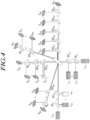
- FIG. 4 is a view for describing a specific configuration of laser generators and photodetectors for illustrating a specific example of irradiating first laser beams at coaxial and different angles and collecting second laser beams generated by the cells, according to an embodiment of the present invention. Specifically, FIG. 4 is a view for describing an example of irradiating first laser beams of multiple frequencies at multiple angles and at the same axis, and collecting the second laser beams by a plurality of photodetectors at different positions.
- components indicated by letters starting with a capital "L” mean all components that can generate a first laser beam, such as a laser diode and a laser irradiation device.
- components indicated by letters starting with a capital “S” mean all components that can function as a photodetector, such as a photo diode and a photomultiplier (PMT).
- Components indicated by letters starting with a capital “M” mean mirrors
- components indicated by letters starting with capitals "BC” mean beam combiners
- components indicated by letters starting with capitals "BS” mean beam splitters.
- laser beams are generated from a plurality of light sources L x1 to L xn in a single-axis laser generator, and the generated laser beams are mixed by mirrors M x1 and beam combiners BC x1 to be irradiated to classification target cells 100 as first laser beams.
- laser beams are also generated from a plurality of light sources L y1 to L yn in the laser generator of the other axis, and the generated laser beams are mixed by mirrors m y1 and beam combiners BC y1 to be irradiated, as first laser beams, to the classification target cells 100 at an angle different from that of the above-mentioned single-axis laser generator.
- the first laser beams including laser beams having at least one frequency are irradiated to the classification target cells 100 at different angles as described above, the first laser beams are transmitted, reflected, refracted, or fluoresced by the classification target cells 100, thereby generating second laser beams.
- a second laser beam generated by the transmission of a beam L x1 is collected at S x3
- a second laser beam generated by the transmission of a beam L xn is collected at S x2
- a second laser beam generated by the transmission of a beam L y1 is collected at S y2
- a second laser beam generated by the transmission of a beam L yn is collected at S yn .
- refracted and reflected beams may be collected as follows.
- second laser beams generated by the refraction or reflection of the beam L x1 are collected at S ⁇ 1 and S ⁇ n , respectively.
- a second laser beam generated by the refraction or reflection of the beam L xn is collected in S y1 .
- a second laser beam generated by the refraction or reflection of the beam L y1 is collected at S x4 , and a second laser beam generated by the refraction or reflection of the light L yn is collected at Sxn.
- fluoresced beams may also be collected.
- the frequency thereof is modulated so that the color of the beam may be changed, which is represented as beams, which are collected at S ⁇ n , S ⁇ 1 , S ⁇ n , and S x1 , respectively, as can be seen from FIG. 4 .
- Each collected beam may be classified and collected at every frequency by the mirrors M ⁇ 1 , M y2 , M ⁇ 1 , and M x2 and optical splitters BS ⁇ n , BS y1 to BS yn , BS ⁇ n , and BS x1 to BS x4 .
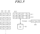
- FIG. 5 is a view for describing a flow in which cells are classified according to the implementation of an embodiment of the present invention.
- information on the collection of the second laser beams transmitted to the cell analysis unit may include identification information 200 of respective photodetectors D1 to D4, frequency information 201 of beams collected by the photodetectors (including F1 to F4), and light amount information 202.
- the cell analysis unit which receives the above-mentioned information, will calculate three-dimensional second laser beam distribution information 210, which may include, for example, cumulative second laser beam density 212 (GT1 to GTn) at each of measurement points 211 (C1 to Cn) set in three dimensions.
- GT1 to GTn cumulative second laser beam density 212
- the three-dimensional second laser beam distribution information is compared with the reference second laser beam information stored in a database 50, and cell type information 300 matching the reference second laser beam information is classified as a classification target cell type.
Landscapes
- Chemical & Material Sciences (AREA)
- Health & Medical Sciences (AREA)
- Life Sciences & Earth Sciences (AREA)
- Analytical Chemistry (AREA)
- Biochemistry (AREA)
- General Health & Medical Sciences (AREA)
- Physics & Mathematics (AREA)
- Immunology (AREA)
- Pathology (AREA)
- General Physics & Mathematics (AREA)
- Engineering & Computer Science (AREA)
- Bioinformatics & Cheminformatics (AREA)
- Dispersion Chemistry (AREA)
- Organic Chemistry (AREA)
- Wood Science & Technology (AREA)
- Biotechnology (AREA)
- Zoology (AREA)
- Biomedical Technology (AREA)
- Genetics & Genomics (AREA)
- Sustainable Development (AREA)
- Microbiology (AREA)
- Medicinal Chemistry (AREA)
- General Engineering & Computer Science (AREA)
- Signal Processing (AREA)
- Optics & Photonics (AREA)
- Investigating Or Analysing Materials By Optical Means (AREA)
- Molecular Biology (AREA)
- Nuclear Medicine, Radiotherapy & Molecular Imaging (AREA)
- Spectroscopy & Molecular Physics (AREA)
- Investigating, Analyzing Materials By Fluorescence Or Luminescence (AREA)
- Investigating Or Analysing Biological Materials (AREA)
Claims (6)
- Zellanalyseeinrichtung, die eine Vielzahl von Lasern verwendet, wobei die Zellanalyseeinrichtung umfasst:eine Vielzahl von Lasergeneratoren (21, 22), die um einen Bewegungspfad (10), durch den Klassifizierungszielzellen (100) bewegt werden, herum installiert und so konfiguriert sind, dass sie zuerst Laserstrahlen als einen oder mehrere Laserstrahlen, die eine oder mehrere Frequenzen aufweisen, auf einen Messpunkt (11), der im Bewegungspfad vorhanden ist, strahlen;eine Vielzahl von Photodetektoren (30; 31, 32, 33, 34, 35), die um den Messpunkt herum installiert und so konfiguriert sind, dass sie zweite Laserstrahlen sammeln, die erzeugt werden, wenn die von den Lasergeneratoren gestrahlten ersten Laserstrahlen auf Zellen auftreffen und dann gebrochen, reflektiert, transmittiert oder fluoresziert werden; undeine Zellanalyseeinheit (40), die so konfiguriert ist, dass sie die Klassifizierungszielzellen (100) gemäß den von den Photodetektoren gesammelten zweiten Laserstrahlen klassifiziert;wobei die Vielzahl von Lasergeneratoren die ersten Laserstrahlen in unterschiedlichen Winkeln auf den Messpunkt (11) strahlen und die Frequenzen der Laserstrahlen, die in den ersten Laserstrahlen beinhaltet sind, sich voneinander unterscheiden;wobei die Zellanalyseeinrichtung dadurch gekennzeichnet ist, dass die Vielzahl von Photodetektoren in dreidimensionalen Bereichen so um den Messpunkt (11) herum installiert sind, dass die Vielzahl von Photodetektoren den Messpunkt dreidimensional umgeben und nicht alle ein einer gemeinsamen Ebene angeordnet sind, und sie in einer Art und Weise vorgesehen sind, in der die zweiten Laserstrahlen unterschiedlicher Frequenzen jeweils von unterschiedlichen Photodetektoren gesammelt werden; unddadurch gekennzeichnet, dass die Zellanalyseeinheit (40) so konfiguriert ist, dass sie die Klassifizierungszielzellen (100) unter Verwendung der Verteilung der zweiten Laserstrahlen und durch die Photoreaktion von Zellen für unterschiedliche Frequenzen klassifiziert.
- Zellanalyseeinrichtung nach Anspruch 1, wobei die Vielzahl von Photodetektoren so angeordnet sind, dass sie den Messpunkt (11) derart umgeben, dass der Messpunkt zentriert ist.
- Zellanalyseeinrichtung nach Anspruch 1, wobei die Vielzahl von Photodetektoren Frequenzen der gesammelten zweiten Laserstrahlen messen, und wenn eine Information über die Lichtmenge der von jedem der Vielzahl von Photodetektoren gesammelten zweiten Laserstrahlen an die Zellanalyseeinheit übertragen wird, die Information über die Lichtmenge in einer Art und Weise übertragen wird, in der die Information über die Lichtmenge die Informationen über die gemessenen Frequenzen der zweiten Laserstrahlen beinhaltet.
- Zellanalyseeinrichtung nach Anspruch 1, wobei die Zellanalyseeinheit Referenzinformationen von zweiten Laserstrahlen speichert, bei denen es sich um Informationen handelt, die durch Abtasten von Informationen über die Verteilung der Lichtmenge einer Vielzahl von dreidimensionalen zweiten Laserstrahlen erhalten werden, die zuvor beim Strahlen von Laserstrahlen auf jeden von zuvor gespeicherten Zelltypen eingestellt werden, und
wobei die Zellanalyseeinheit die Lichtmenge der zweiten Laserstrahlen, die von jedem der Vielzahl von Photodetektoren empfangen und gesammelt werden, bei jeder Frequenz berechnet, um Informationen über die Verteilung von dreidimensionalen zweiten Laserstrahlen zu berechnen, und die berechneten Informationen über die Verteilung von dreidimensionalen zweiten Laserstrahlen und die Referenzinformationen von zweiten Laserstrahlen vergleicht, um die Klassifizierungszielzellen mit einem der zuvor gespeicherten Zelltypen abzugleichen. - Zellanalyseeinrichtung nach Anspruch 4, wobei die zuvor gespeicherten Zelltypen mindestens einen normalen Zelltyp und mindestens einen abnormalen Zelltyp beinhalten.
- Zellanalyseeinrichtung nach Anspruch 1, wobei mindestens einige der Vielzahl von Lasergeneratoren derart vorgesehen sind, dass die Vielzahl von Laserstrahlen als die ersten Laserstrahlen durch koaxiales Strahlen einer Vielzahl von Laserstrahlen, die eine Vielzahl von Frequenzen aufweisen, gestrahlt werden.
Applications Claiming Priority (2)
| Application Number | Priority Date | Filing Date | Title |
|---|---|---|---|
| KR1020150109036A KR101681422B1 (ko) | 2015-07-31 | 2015-07-31 | 다수의 레이저를 사용하는 세포 분석 장치 |
| PCT/KR2015/011417 WO2017022885A1 (ko) | 2015-07-31 | 2015-10-28 | 다수의 레이저를 사용하는 세포 분석 장치 |
Publications (3)
| Publication Number | Publication Date |
|---|---|
| EP3330367A1 EP3330367A1 (de) | 2018-06-06 |
| EP3330367A4 EP3330367A4 (de) | 2019-05-15 |
| EP3330367B1 true EP3330367B1 (de) | 2024-07-31 |
Family
ID=57707325
Family Applications (1)
| Application Number | Title | Priority Date | Filing Date |
|---|---|---|---|
| EP15900471.2A Active EP3330367B1 (de) | 2015-07-31 | 2015-10-28 | Zellanalysevorrichtung unter verwendung mehrerer laser |
Country Status (5)
| Country | Link |
|---|---|
| US (1) | US10429293B2 (de) |
| EP (1) | EP3330367B1 (de) |
| KR (1) | KR101681422B1 (de) |
| CN (1) | CN107250761B (de) |
| WO (1) | WO2017022885A1 (de) |
Families Citing this family (9)
| Publication number | Priority date | Publication date | Assignee | Title |
|---|---|---|---|---|
| KR101934926B1 (ko) * | 2017-01-10 | 2019-01-03 | 충남대학교산학협력단 | 유동 유체 내의 나노입자 거동 예측 방법 및 장치 |
| KR102122020B1 (ko) * | 2018-09-04 | 2020-06-12 | 경북대학교 산학협력단 | 혈구 분석 장치, 이를 이용한 혈구 분석 방법 |
| CN110146430B (zh) * | 2019-05-29 | 2024-10-15 | 中国科学院苏州生物医学工程技术研究所 | 一种流式细胞仪光学系统 |
| EP3922977B1 (de) * | 2020-06-08 | 2024-08-07 | Universität für Bodenkultur Wien | Verfahren zur bestimmung einer eigenschaft eines partikels in einem medium |
| CN112147044A (zh) * | 2020-09-07 | 2020-12-29 | 桂林电子科技大学 | 用于流式细胞仪的光谱细分式光纤集散探测装置 |
| CN112229781A (zh) * | 2020-09-07 | 2021-01-15 | 桂林电子科技大学 | 一种改进的流式细胞仪的光谱细分式光纤集散探测装置 |
| US20240410811A1 (en) * | 2022-01-21 | 2024-12-12 | Hitachi High-Tech Corporation | Particle Measuring Apparatus |
| CN116793907B (zh) * | 2022-03-16 | 2024-05-14 | 上海勘测设计研究院有限公司 | 一种多方位衍射散射式粒度仪及颗分检测方法 |
| CN118243665B (zh) * | 2024-04-01 | 2025-02-07 | 国网宁夏电力有限公司电力科学研究院 | 一种变压器油的油品质流式检测装置 |
Family Cites Families (11)
| Publication number | Priority date | Publication date | Assignee | Title |
|---|---|---|---|---|
| US5041733A (en) * | 1987-03-20 | 1991-08-20 | Agency Of Industrial Science & Technology | Method and apparatus for identifying chromosomes or cells |
| JPH0560751A (ja) | 1991-09-05 | 1993-03-12 | Omron Corp | 細胞分析装置 |
| JPH0996603A (ja) | 1995-09-29 | 1997-04-08 | Sumitomo Electric Ind Ltd | 流動細胞分析装置 |
| US6591003B2 (en) * | 2001-03-28 | 2003-07-08 | Visiongate, Inc. | Optical tomography of small moving objects using time delay and integration imaging |
| JP2006010630A (ja) * | 2004-06-29 | 2006-01-12 | Sysmex Corp | 異常細胞の検出装置およびその検出方法 |
| JP4756948B2 (ja) * | 2005-08-08 | 2011-08-24 | ベイバイオサイエンス株式会社 | フローサイトメータおよびフローサイトメトリ方法 |
| CN100507635C (zh) | 2007-12-12 | 2009-07-01 | 浙江大学 | 一种用于运输和定向移动微粒和细胞的激光微控装置及方法 |
| WO2009098867A1 (ja) | 2008-02-07 | 2009-08-13 | Mitsui Engineering & Shipbuilding Co., Ltd. | 蛍光検出装置および蛍光検出方法 |
| CA2992239C (en) | 2008-08-21 | 2020-02-25 | Xy, Llc | Cell analysis apparatus and methods |
| KR101250751B1 (ko) | 2010-10-22 | 2013-04-03 | 연세대학교 산학협력단 | 다중 형광 정도 이용 세포 분리 장치 및 전극구조와 다중 형광 정도 이용 세포 분리 방법 |
| JP6121319B2 (ja) | 2013-03-29 | 2017-04-26 | シスメックス株式会社 | 粒子測定装置、照射光学系および照射位置調整方法 |
-
2015
- 2015-07-31 KR KR1020150109036A patent/KR101681422B1/ko not_active Expired - Fee Related
- 2015-10-28 US US15/541,287 patent/US10429293B2/en active Active
- 2015-10-28 WO PCT/KR2015/011417 patent/WO2017022885A1/ko not_active Ceased
- 2015-10-28 EP EP15900471.2A patent/EP3330367B1/de active Active
- 2015-10-28 CN CN201580077102.6A patent/CN107250761B/zh active Active
Also Published As
| Publication number | Publication date |
|---|---|
| CN107250761B (zh) | 2020-03-06 |
| EP3330367A4 (de) | 2019-05-15 |
| US10429293B2 (en) | 2019-10-01 |
| WO2017022885A1 (ko) | 2017-02-09 |
| CN107250761A (zh) | 2017-10-13 |
| EP3330367A1 (de) | 2018-06-06 |
| US20170363532A1 (en) | 2017-12-21 |
| KR101681422B1 (ko) | 2016-11-30 |
Similar Documents
| Publication | Publication Date | Title |
|---|---|---|
| EP3330367B1 (de) | Zellanalysevorrichtung unter verwendung mehrerer laser | |
| US10429291B2 (en) | Multi-spectral filter profiling and quality control for flow cytometry | |
| US10018550B2 (en) | System and method for analyzing blood cell | |
| US9372143B2 (en) | Scanning image flow cytometer | |
| JP5381741B2 (ja) | 光学的測定装置及び光学的測定方法 | |
| CN101000306A (zh) | 细胞分析仪 | |
| US11674877B2 (en) | Apparatus and method for cyclic flow cytometry using particularized cell identification | |
| CN112485167A (zh) | 粒子分析仪的光学系统 | |
| US11204310B2 (en) | Optical flow cytometer for epi fluorescence measurement | |
| US9594011B2 (en) | Method and instrumentation for determining a physical property of a particle | |
| EP2869054A1 (de) | Verbesserungen in Zusammenhang mit Partikelcharakterisierung | |
| US10663393B2 (en) | Spectrum inspecting apparatus | |
| WO2017060164A1 (en) | Optical sensor for particle detection | |
| EP3335031B1 (de) | Multispektrale filterprofilierung und qualitätskontrolle für durchflusszytometrie | |
| EP2869057A1 (de) | Verbesserungen in Zusammenhang mit Partikelcharakterisierung | |
| EP2869056A1 (de) | Verbesserungen in Zusammenhang mit Partikelcharakterisierung | |
| KR102122020B1 (ko) | 혈구 분석 장치, 이를 이용한 혈구 분석 방법 | |
| CN106290173A (zh) | 气体浓度多维分布的检测装置及方法 | |
| EP4632350A1 (de) | Quantitative durchflusszytometrie-lichtstreuungsdetektorausrichtung | |
| JPS6244649A (ja) | 粒子解析装置 | |
| EP2869055A1 (de) | Verbesserungen in Zusammenhang mit Partikelcharakterisierung | |
| JP2005331277A (ja) | 光散乱による試料特性計測装置および計測方法 | |
| JP2004271340A (ja) | 粒径分布測定装置 |
Legal Events
| Date | Code | Title | Description |
|---|---|---|---|
| STAA | Information on the status of an ep patent application or granted ep patent |
Free format text: STATUS: THE INTERNATIONAL PUBLICATION HAS BEEN MADE |
|
| PUAI | Public reference made under article 153(3) epc to a published international application that has entered the european phase |
Free format text: ORIGINAL CODE: 0009012 |
|
| STAA | Information on the status of an ep patent application or granted ep patent |
Free format text: STATUS: REQUEST FOR EXAMINATION WAS MADE |
|
| 17P | Request for examination filed |
Effective date: 20170818 |
|
| AK | Designated contracting states |
Kind code of ref document: A1 Designated state(s): AL AT BE BG CH CY CZ DE DK EE ES FI FR GB GR HR HU IE IS IT LI LT LU LV MC MK MT NL NO PL PT RO RS SE SI SK SM TR |
|
| AX | Request for extension of the european patent |
Extension state: BA ME |
|
| DAV | Request for validation of the european patent (deleted) | ||
| DAX | Request for extension of the european patent (deleted) | ||
| A4 | Supplementary search report drawn up and despatched |
Effective date: 20190411 |
|
| RIC1 | Information provided on ipc code assigned before grant |
Ipc: G01N 21/41 20060101ALI20190405BHEP Ipc: G01N 21/55 20140101ALI20190405BHEP Ipc: G01N 15/14 20060101ALI20190405BHEP Ipc: C12M 1/34 20060101AFI20190405BHEP |
|
| STAA | Information on the status of an ep patent application or granted ep patent |
Free format text: STATUS: EXAMINATION IS IN PROGRESS |
|
| 17Q | First examination report despatched |
Effective date: 20220202 |
|
| GRAP | Despatch of communication of intention to grant a patent |
Free format text: ORIGINAL CODE: EPIDOSNIGR1 |
|
| STAA | Information on the status of an ep patent application or granted ep patent |
Free format text: STATUS: GRANT OF PATENT IS INTENDED |
|
| INTG | Intention to grant announced |
Effective date: 20240227 |
|
| GRAS | Grant fee paid |
Free format text: ORIGINAL CODE: EPIDOSNIGR3 |
|
| GRAA | (expected) grant |
Free format text: ORIGINAL CODE: 0009210 |
|
| STAA | Information on the status of an ep patent application or granted ep patent |
Free format text: STATUS: THE PATENT HAS BEEN GRANTED |
|
| AK | Designated contracting states |
Kind code of ref document: B1 Designated state(s): AL AT BE BG CH CY CZ DE DK EE ES FI FR GB GR HR HU IE IS IT LI LT LU LV MC MK MT NL NO PL PT RO RS SE SI SK SM TR |
|
| REG | Reference to a national code |
Ref country code: CH Ref legal event code: EP Ref country code: GB Ref legal event code: FG4D |
|
| REG | Reference to a national code |
Ref country code: DE Ref legal event code: R096 Ref document number: 602015089418 Country of ref document: DE |
|
| REG | Reference to a national code |
Ref country code: IE Ref legal event code: FG4D |
|
| REG | Reference to a national code |
Ref country code: LT Ref legal event code: MG9D |
|
| REG | Reference to a national code |
Ref country code: NL Ref legal event code: MP Effective date: 20240731 |
|
| PG25 | Lapsed in a contracting state [announced via postgrant information from national office to epo] |
Ref country code: PT Free format text: LAPSE BECAUSE OF FAILURE TO SUBMIT A TRANSLATION OF THE DESCRIPTION OR TO PAY THE FEE WITHIN THE PRESCRIBED TIME-LIMIT Effective date: 20241202 |
|
| REG | Reference to a national code |
Ref country code: AT Ref legal event code: MK05 Ref document number: 1708485 Country of ref document: AT Kind code of ref document: T Effective date: 20240731 |
|
| PG25 | Lapsed in a contracting state [announced via postgrant information from national office to epo] |
Ref country code: PT Free format text: LAPSE BECAUSE OF FAILURE TO SUBMIT A TRANSLATION OF THE DESCRIPTION OR TO PAY THE FEE WITHIN THE PRESCRIBED TIME-LIMIT Effective date: 20241202 |
|
| PG25 | Lapsed in a contracting state [announced via postgrant information from national office to epo] |
Ref country code: NO Free format text: LAPSE BECAUSE OF FAILURE TO SUBMIT A TRANSLATION OF THE DESCRIPTION OR TO PAY THE FEE WITHIN THE PRESCRIBED TIME-LIMIT Effective date: 20241031 |
|
| PG25 | Lapsed in a contracting state [announced via postgrant information from national office to epo] |
Ref country code: PL Free format text: LAPSE BECAUSE OF FAILURE TO SUBMIT A TRANSLATION OF THE DESCRIPTION OR TO PAY THE FEE WITHIN THE PRESCRIBED TIME-LIMIT Effective date: 20240731 Ref country code: FI Free format text: LAPSE BECAUSE OF FAILURE TO SUBMIT A TRANSLATION OF THE DESCRIPTION OR TO PAY THE FEE WITHIN THE PRESCRIBED TIME-LIMIT Effective date: 20240731 Ref country code: GR Free format text: LAPSE BECAUSE OF FAILURE TO SUBMIT A TRANSLATION OF THE DESCRIPTION OR TO PAY THE FEE WITHIN THE PRESCRIBED TIME-LIMIT Effective date: 20241101 Ref country code: NL Free format text: LAPSE BECAUSE OF FAILURE TO SUBMIT A TRANSLATION OF THE DESCRIPTION OR TO PAY THE FEE WITHIN THE PRESCRIBED TIME-LIMIT Effective date: 20240731 |
|
| PG25 | Lapsed in a contracting state [announced via postgrant information from national office to epo] |
Ref country code: BG Free format text: LAPSE BECAUSE OF FAILURE TO SUBMIT A TRANSLATION OF THE DESCRIPTION OR TO PAY THE FEE WITHIN THE PRESCRIBED TIME-LIMIT Effective date: 20240731 |
|
| PG25 | Lapsed in a contracting state [announced via postgrant information from national office to epo] |
Ref country code: LV Free format text: LAPSE BECAUSE OF FAILURE TO SUBMIT A TRANSLATION OF THE DESCRIPTION OR TO PAY THE FEE WITHIN THE PRESCRIBED TIME-LIMIT Effective date: 20240731 |
|
| PG25 | Lapsed in a contracting state [announced via postgrant information from national office to epo] |
Ref country code: IS Free format text: LAPSE BECAUSE OF FAILURE TO SUBMIT A TRANSLATION OF THE DESCRIPTION OR TO PAY THE FEE WITHIN THE PRESCRIBED TIME-LIMIT Effective date: 20241130 Ref country code: AT Free format text: LAPSE BECAUSE OF FAILURE TO SUBMIT A TRANSLATION OF THE DESCRIPTION OR TO PAY THE FEE WITHIN THE PRESCRIBED TIME-LIMIT Effective date: 20240731 |
|
| PG25 | Lapsed in a contracting state [announced via postgrant information from national office to epo] |
Ref country code: HR Free format text: LAPSE BECAUSE OF FAILURE TO SUBMIT A TRANSLATION OF THE DESCRIPTION OR TO PAY THE FEE WITHIN THE PRESCRIBED TIME-LIMIT Effective date: 20240731 |
|
| PG25 | Lapsed in a contracting state [announced via postgrant information from national office to epo] |
Ref country code: ES Free format text: LAPSE BECAUSE OF FAILURE TO SUBMIT A TRANSLATION OF THE DESCRIPTION OR TO PAY THE FEE WITHIN THE PRESCRIBED TIME-LIMIT Effective date: 20240731 Ref country code: RS Free format text: LAPSE BECAUSE OF FAILURE TO SUBMIT A TRANSLATION OF THE DESCRIPTION OR TO PAY THE FEE WITHIN THE PRESCRIBED TIME-LIMIT Effective date: 20241031 |
|
| PG25 | Lapsed in a contracting state [announced via postgrant information from national office to epo] |
Ref country code: RS Free format text: LAPSE BECAUSE OF FAILURE TO SUBMIT A TRANSLATION OF THE DESCRIPTION OR TO PAY THE FEE WITHIN THE PRESCRIBED TIME-LIMIT Effective date: 20241031 Ref country code: PL Free format text: LAPSE BECAUSE OF FAILURE TO SUBMIT A TRANSLATION OF THE DESCRIPTION OR TO PAY THE FEE WITHIN THE PRESCRIBED TIME-LIMIT Effective date: 20240731 Ref country code: NO Free format text: LAPSE BECAUSE OF FAILURE TO SUBMIT A TRANSLATION OF THE DESCRIPTION OR TO PAY THE FEE WITHIN THE PRESCRIBED TIME-LIMIT Effective date: 20241031 Ref country code: NL Free format text: LAPSE BECAUSE OF FAILURE TO SUBMIT A TRANSLATION OF THE DESCRIPTION OR TO PAY THE FEE WITHIN THE PRESCRIBED TIME-LIMIT Effective date: 20240731 Ref country code: LV Free format text: LAPSE BECAUSE OF FAILURE TO SUBMIT A TRANSLATION OF THE DESCRIPTION OR TO PAY THE FEE WITHIN THE PRESCRIBED TIME-LIMIT Effective date: 20240731 Ref country code: IS Free format text: LAPSE BECAUSE OF FAILURE TO SUBMIT A TRANSLATION OF THE DESCRIPTION OR TO PAY THE FEE WITHIN THE PRESCRIBED TIME-LIMIT Effective date: 20241130 Ref country code: HR Free format text: LAPSE BECAUSE OF FAILURE TO SUBMIT A TRANSLATION OF THE DESCRIPTION OR TO PAY THE FEE WITHIN THE PRESCRIBED TIME-LIMIT Effective date: 20240731 Ref country code: GR Free format text: LAPSE BECAUSE OF FAILURE TO SUBMIT A TRANSLATION OF THE DESCRIPTION OR TO PAY THE FEE WITHIN THE PRESCRIBED TIME-LIMIT Effective date: 20241101 Ref country code: FI Free format text: LAPSE BECAUSE OF FAILURE TO SUBMIT A TRANSLATION OF THE DESCRIPTION OR TO PAY THE FEE WITHIN THE PRESCRIBED TIME-LIMIT Effective date: 20240731 Ref country code: ES Free format text: LAPSE BECAUSE OF FAILURE TO SUBMIT A TRANSLATION OF THE DESCRIPTION OR TO PAY THE FEE WITHIN THE PRESCRIBED TIME-LIMIT Effective date: 20240731 Ref country code: BG Free format text: LAPSE BECAUSE OF FAILURE TO SUBMIT A TRANSLATION OF THE DESCRIPTION OR TO PAY THE FEE WITHIN THE PRESCRIBED TIME-LIMIT Effective date: 20240731 Ref country code: AT Free format text: LAPSE BECAUSE OF FAILURE TO SUBMIT A TRANSLATION OF THE DESCRIPTION OR TO PAY THE FEE WITHIN THE PRESCRIBED TIME-LIMIT Effective date: 20240731 |
|
| PG25 | Lapsed in a contracting state [announced via postgrant information from national office to epo] |
Ref country code: SM Free format text: LAPSE BECAUSE OF FAILURE TO SUBMIT A TRANSLATION OF THE DESCRIPTION OR TO PAY THE FEE WITHIN THE PRESCRIBED TIME-LIMIT Effective date: 20240731 Ref country code: RO Free format text: LAPSE BECAUSE OF FAILURE TO SUBMIT A TRANSLATION OF THE DESCRIPTION OR TO PAY THE FEE WITHIN THE PRESCRIBED TIME-LIMIT Effective date: 20240731 Ref country code: DK Free format text: LAPSE BECAUSE OF FAILURE TO SUBMIT A TRANSLATION OF THE DESCRIPTION OR TO PAY THE FEE WITHIN THE PRESCRIBED TIME-LIMIT Effective date: 20240731 |
|
| PG25 | Lapsed in a contracting state [announced via postgrant information from national office to epo] |
Ref country code: EE Free format text: LAPSE BECAUSE OF FAILURE TO SUBMIT A TRANSLATION OF THE DESCRIPTION OR TO PAY THE FEE WITHIN THE PRESCRIBED TIME-LIMIT Effective date: 20240731 |
|
| PG25 | Lapsed in a contracting state [announced via postgrant information from national office to epo] |
Ref country code: CZ Free format text: LAPSE BECAUSE OF FAILURE TO SUBMIT A TRANSLATION OF THE DESCRIPTION OR TO PAY THE FEE WITHIN THE PRESCRIBED TIME-LIMIT Effective date: 20240731 |
|
| PG25 | Lapsed in a contracting state [announced via postgrant information from national office to epo] |
Ref country code: SK Free format text: LAPSE BECAUSE OF FAILURE TO SUBMIT A TRANSLATION OF THE DESCRIPTION OR TO PAY THE FEE WITHIN THE PRESCRIBED TIME-LIMIT Effective date: 20240731 Ref country code: IT Free format text: LAPSE BECAUSE OF FAILURE TO SUBMIT A TRANSLATION OF THE DESCRIPTION OR TO PAY THE FEE WITHIN THE PRESCRIBED TIME-LIMIT Effective date: 20240731 |
|
| REG | Reference to a national code |
Ref country code: DE Ref legal event code: R119 Ref document number: 602015089418 Country of ref document: DE |
|
| REG | Reference to a national code |
Ref country code: CH Ref legal event code: PL |
|
| PLBE | No opposition filed within time limit |
Free format text: ORIGINAL CODE: 0009261 |
|
| STAA | Information on the status of an ep patent application or granted ep patent |
Free format text: STATUS: NO OPPOSITION FILED WITHIN TIME LIMIT |
|
| PG25 | Lapsed in a contracting state [announced via postgrant information from national office to epo] |
Ref country code: MC Free format text: LAPSE BECAUSE OF FAILURE TO SUBMIT A TRANSLATION OF THE DESCRIPTION OR TO PAY THE FEE WITHIN THE PRESCRIBED TIME-LIMIT Effective date: 20240731 |
|
| 26N | No opposition filed |
Effective date: 20250501 |
|
| PG25 | Lapsed in a contracting state [announced via postgrant information from national office to epo] |
Ref country code: DE Free format text: LAPSE BECAUSE OF NON-PAYMENT OF DUE FEES Effective date: 20250501 |
|
| PG25 | Lapsed in a contracting state [announced via postgrant information from national office to epo] |
Ref country code: BE Free format text: LAPSE BECAUSE OF NON-PAYMENT OF DUE FEES Effective date: 20241031 Ref country code: LU Free format text: LAPSE BECAUSE OF NON-PAYMENT OF DUE FEES Effective date: 20241028 |
|
| PG25 | Lapsed in a contracting state [announced via postgrant information from national office to epo] |
Ref country code: FR Free format text: LAPSE BECAUSE OF NON-PAYMENT OF DUE FEES Effective date: 20241031 |
|
| PG25 | Lapsed in a contracting state [announced via postgrant information from national office to epo] |
Ref country code: CH Free format text: LAPSE BECAUSE OF NON-PAYMENT OF DUE FEES Effective date: 20241031 |
|
| REG | Reference to a national code |
Ref country code: BE Ref legal event code: MM Effective date: 20241031 |
|
| PG25 | Lapsed in a contracting state [announced via postgrant information from national office to epo] |
Ref country code: SE Free format text: LAPSE BECAUSE OF FAILURE TO SUBMIT A TRANSLATION OF THE DESCRIPTION OR TO PAY THE FEE WITHIN THE PRESCRIBED TIME-LIMIT Effective date: 20240731 |
|
| PG25 | Lapsed in a contracting state [announced via postgrant information from national office to epo] |
Ref country code: IE Free format text: LAPSE BECAUSE OF NON-PAYMENT OF DUE FEES Effective date: 20241028 |
|
| PGFP | Annual fee paid to national office [announced via postgrant information from national office to epo] |
Ref country code: GB Payment date: 20251001 Year of fee payment: 11 |
|
| PG25 | Lapsed in a contracting state [announced via postgrant information from national office to epo] |
Ref country code: HU Free format text: LAPSE BECAUSE OF FAILURE TO SUBMIT A TRANSLATION OF THE DESCRIPTION OR TO PAY THE FEE WITHIN THE PRESCRIBED TIME-LIMIT; INVALID AB INITIO Effective date: 20151028 |
|
| PG25 | Lapsed in a contracting state [announced via postgrant information from national office to epo] |
Ref country code: CY Free format text: LAPSE BECAUSE OF FAILURE TO SUBMIT A TRANSLATION OF THE DESCRIPTION OR TO PAY THE FEE WITHIN THE PRESCRIBED TIME-LIMIT; INVALID AB INITIO Effective date: 20151028 |