EP3330188B1 - Multifunktionelle struktur zur verwaltung von elektrischer energie und mechanischer umgebung - Google Patents
Multifunktionelle struktur zur verwaltung von elektrischer energie und mechanischer umgebung Download PDFInfo
- Publication number
- EP3330188B1 EP3330188B1 EP16901184.8A EP16901184A EP3330188B1 EP 3330188 B1 EP3330188 B1 EP 3330188B1 EP 16901184 A EP16901184 A EP 16901184A EP 3330188 B1 EP3330188 B1 EP 3330188B1
- Authority
- EP
- European Patent Office
- Prior art keywords
- power source
- framework
- cover plate
- elastic
- source module
- Prior art date
- Legal status (The legal status is an assumption and is not a legal conclusion. Google has not performed a legal analysis and makes no representation as to the accuracy of the status listed.)
- Active
Links
- 230000001133 acceleration Effects 0.000 claims description 47
- RYGMFSIKBFXOCR-UHFFFAOYSA-N Copper Chemical compound [Cu] RYGMFSIKBFXOCR-UHFFFAOYSA-N 0.000 claims description 44
- 230000009467 reduction Effects 0.000 claims description 33
- 239000000853 adhesive Substances 0.000 claims description 28
- 230000001070 adhesive effect Effects 0.000 claims description 28
- 239000000463 material Substances 0.000 claims description 25
- 239000011889 copper foil Substances 0.000 claims description 23
- 229920000049 Carbon (fiber) Polymers 0.000 claims description 18
- 239000004917 carbon fiber Substances 0.000 claims description 18
- VNWKTOKETHGBQD-UHFFFAOYSA-N methane Chemical compound C VNWKTOKETHGBQD-UHFFFAOYSA-N 0.000 claims description 18
- 239000010949 copper Substances 0.000 claims description 12
- 229910052802 copper Inorganic materials 0.000 claims description 12
- 239000002131 composite material Substances 0.000 claims description 10
- 230000000670 limiting effect Effects 0.000 claims description 10
- WHXSMMKQMYFTQS-UHFFFAOYSA-N Lithium Chemical compound [Li] WHXSMMKQMYFTQS-UHFFFAOYSA-N 0.000 claims description 9
- 238000001514 detection method Methods 0.000 claims description 9
- 229910052744 lithium Inorganic materials 0.000 claims description 9
- 229910001069 Ti alloy Inorganic materials 0.000 claims description 8
- 239000012790 adhesive layer Substances 0.000 claims description 8
- 238000009434 installation Methods 0.000 claims description 8
- 239000000956 alloy Substances 0.000 claims description 6
- 238000013016 damping Methods 0.000 claims description 6
- 238000012544 monitoring process Methods 0.000 claims description 6
- 239000004642 Polyimide Substances 0.000 claims description 5
- 239000011810 insulating material Substances 0.000 claims description 5
- 229920001721 polyimide Polymers 0.000 claims description 5
- 238000004026 adhesive bonding Methods 0.000 claims description 4
- 230000005540 biological transmission Effects 0.000 claims description 4
- 238000000034 method Methods 0.000 claims description 4
- 230000008569 process Effects 0.000 claims description 4
- 230000002301 combined effect Effects 0.000 claims description 3
- 238000001816 cooling Methods 0.000 claims description 3
- 239000004205 dimethyl polysiloxane Substances 0.000 claims description 3
- 238000007599 discharging Methods 0.000 claims description 3
- 230000005489 elastic deformation Effects 0.000 claims description 3
- 238000009413 insulation Methods 0.000 claims description 3
- 229920000435 poly(dimethylsiloxane) Polymers 0.000 claims description 3
- -1 polydimethylsiloxane Polymers 0.000 claims description 3
- 239000000126 substance Substances 0.000 claims description 3
- 230000006835 compression Effects 0.000 claims description 2
- 238000007906 compression Methods 0.000 claims description 2
- 238000006073 displacement reaction Methods 0.000 claims description 2
- 238000010586 diagram Methods 0.000 description 7
- 239000002356 single layer Substances 0.000 description 6
- 229920002379 silicone rubber Polymers 0.000 description 5
- 238000013461 design Methods 0.000 description 4
- 230000007613 environmental effect Effects 0.000 description 4
- 238000005259 measurement Methods 0.000 description 4
- 230000004044 response Effects 0.000 description 4
- 239000004945 silicone rubber Substances 0.000 description 4
- 238000012360 testing method Methods 0.000 description 4
- 229920001971 elastomer Polymers 0.000 description 3
- 238000004146 energy storage Methods 0.000 description 3
- 230000001174 ascending effect Effects 0.000 description 2
- 238000005516 engineering process Methods 0.000 description 2
- 230000010354 integration Effects 0.000 description 2
- 230000036961 partial effect Effects 0.000 description 2
- 238000006722 reduction reaction Methods 0.000 description 2
- 238000005382 thermal cycling Methods 0.000 description 2
- 230000000703 anti-shock Effects 0.000 description 1
- 230000000712 assembly Effects 0.000 description 1
- 238000000429 assembly Methods 0.000 description 1
- 230000002238 attenuated effect Effects 0.000 description 1
- 230000009286 beneficial effect Effects 0.000 description 1
- 239000002775 capsule Substances 0.000 description 1
- 239000011248 coating agent Substances 0.000 description 1
- 238000000576 coating method Methods 0.000 description 1
- 230000003247 decreasing effect Effects 0.000 description 1
- 230000007812 deficiency Effects 0.000 description 1
- 230000001419 dependent effect Effects 0.000 description 1
- 230000000694 effects Effects 0.000 description 1
- 239000013013 elastic material Substances 0.000 description 1
- 230000005611 electricity Effects 0.000 description 1
- 230000005284 excitation Effects 0.000 description 1
- 239000004744 fabric Substances 0.000 description 1
- 239000000835 fiber Substances 0.000 description 1
- 230000002829 reductive effect Effects 0.000 description 1
- 238000012827 research and development Methods 0.000 description 1
- 239000007787 solid Substances 0.000 description 1
- 238000012546 transfer Methods 0.000 description 1
Images










Classifications
-
- B—PERFORMING OPERATIONS; TRANSPORTING
- B64—AIRCRAFT; AVIATION; COSMONAUTICS
- B64G—COSMONAUTICS; VEHICLES OR EQUIPMENT THEREFOR
- B64G1/00—Cosmonautic vehicles
- B64G1/22—Parts of, or equipment specially adapted for fitting in or to, cosmonautic vehicles
-
- B—PERFORMING OPERATIONS; TRANSPORTING
- B64—AIRCRAFT; AVIATION; COSMONAUTICS
- B64G—COSMONAUTICS; VEHICLES OR EQUIPMENT THEREFOR
- B64G1/00—Cosmonautic vehicles
- B64G1/22—Parts of, or equipment specially adapted for fitting in or to, cosmonautic vehicles
- B64G1/42—Arrangements or adaptations of power supply systems
- B64G1/425—Power storage
-
- B—PERFORMING OPERATIONS; TRANSPORTING
- B64—AIRCRAFT; AVIATION; COSMONAUTICS
- B64G—COSMONAUTICS; VEHICLES OR EQUIPMENT THEREFOR
- B64G1/00—Cosmonautic vehicles
- B64G1/10—Artificial satellites; Systems of such satellites; Interplanetary vehicles
-
- B—PERFORMING OPERATIONS; TRANSPORTING
- B64—AIRCRAFT; AVIATION; COSMONAUTICS
- B64G—COSMONAUTICS; VEHICLES OR EQUIPMENT THEREFOR
- B64G1/00—Cosmonautic vehicles
- B64G1/22—Parts of, or equipment specially adapted for fitting in or to, cosmonautic vehicles
- B64G1/223—Modular spacecraft systems
-
- B—PERFORMING OPERATIONS; TRANSPORTING
- B64—AIRCRAFT; AVIATION; COSMONAUTICS
- B64G—COSMONAUTICS; VEHICLES OR EQUIPMENT THEREFOR
- B64G1/00—Cosmonautic vehicles
- B64G1/22—Parts of, or equipment specially adapted for fitting in or to, cosmonautic vehicles
- B64G1/228—Damping of high-frequency vibration effects on spacecraft elements, e.g. by using acoustic vibration dampers
-
- B—PERFORMING OPERATIONS; TRANSPORTING
- B64—AIRCRAFT; AVIATION; COSMONAUTICS
- B64G—COSMONAUTICS; VEHICLES OR EQUIPMENT THEREFOR
- B64G1/00—Cosmonautic vehicles
- B64G1/22—Parts of, or equipment specially adapted for fitting in or to, cosmonautic vehicles
- B64G1/46—Arrangements or adaptations of devices for control of environment or living conditions
- B64G1/50—Arrangements or adaptations of devices for control of environment or living conditions for temperature control
-
- B—PERFORMING OPERATIONS; TRANSPORTING
- B64—AIRCRAFT; AVIATION; COSMONAUTICS
- B64G—COSMONAUTICS; VEHICLES OR EQUIPMENT THEREFOR
- B64G1/00—Cosmonautic vehicles
- B64G1/22—Parts of, or equipment specially adapted for fitting in or to, cosmonautic vehicles
- B64G1/66—Arrangements or adaptations of apparatus or instruments, not otherwise provided for
-
- F—MECHANICAL ENGINEERING; LIGHTING; HEATING; WEAPONS; BLASTING
- F16—ENGINEERING ELEMENTS AND UNITS; GENERAL MEASURES FOR PRODUCING AND MAINTAINING EFFECTIVE FUNCTIONING OF MACHINES OR INSTALLATIONS; THERMAL INSULATION IN GENERAL
- F16F—SPRINGS; SHOCK-ABSORBERS; MEANS FOR DAMPING VIBRATION
- F16F7/00—Vibration-dampers; Shock-absorbers
- F16F7/10—Vibration-dampers; Shock-absorbers using inertia effect
- F16F7/104—Vibration-dampers; Shock-absorbers using inertia effect the inertia member being resiliently mounted
-
- H—ELECTRICITY
- H01—ELECTRIC ELEMENTS
- H01M—PROCESSES OR MEANS, e.g. BATTERIES, FOR THE DIRECT CONVERSION OF CHEMICAL ENERGY INTO ELECTRICAL ENERGY
- H01M10/00—Secondary cells; Manufacture thereof
- H01M10/05—Accumulators with non-aqueous electrolyte
- H01M10/052—Li-accumulators
-
- H—ELECTRICITY
- H01—ELECTRIC ELEMENTS
- H01M—PROCESSES OR MEANS, e.g. BATTERIES, FOR THE DIRECT CONVERSION OF CHEMICAL ENERGY INTO ELECTRICAL ENERGY
- H01M50/00—Constructional details or processes of manufacture of the non-active parts of electrochemical cells other than fuel cells, e.g. hybrid cells
- H01M50/20—Mountings; Secondary casings or frames; Racks, modules or packs; Suspension devices; Shock absorbers; Transport or carrying devices; Holders
- H01M50/271—Lids or covers for the racks or secondary casings
-
- F—MECHANICAL ENGINEERING; LIGHTING; HEATING; WEAPONS; BLASTING
- F16—ENGINEERING ELEMENTS AND UNITS; GENERAL MEASURES FOR PRODUCING AND MAINTAINING EFFECTIVE FUNCTIONING OF MACHINES OR INSTALLATIONS; THERMAL INSULATION IN GENERAL
- F16F—SPRINGS; SHOCK-ABSORBERS; MEANS FOR DAMPING VIBRATION
- F16F15/00—Suppression of vibrations in systems; Means or arrangements for avoiding or reducing out-of-balance forces, e.g. due to motion
- F16F15/02—Suppression of vibrations of non-rotating, e.g. reciprocating systems; Suppression of vibrations of rotating systems by use of members not moving with the rotating systems
-
- F—MECHANICAL ENGINEERING; LIGHTING; HEATING; WEAPONS; BLASTING
- F16—ENGINEERING ELEMENTS AND UNITS; GENERAL MEASURES FOR PRODUCING AND MAINTAINING EFFECTIVE FUNCTIONING OF MACHINES OR INSTALLATIONS; THERMAL INSULATION IN GENERAL
- F16F—SPRINGS; SHOCK-ABSORBERS; MEANS FOR DAMPING VIBRATION
- F16F15/00—Suppression of vibrations in systems; Means or arrangements for avoiding or reducing out-of-balance forces, e.g. due to motion
- F16F15/02—Suppression of vibrations of non-rotating, e.g. reciprocating systems; Suppression of vibrations of rotating systems by use of members not moving with the rotating systems
- F16F15/022—Suppression of vibrations of non-rotating, e.g. reciprocating systems; Suppression of vibrations of rotating systems by use of members not moving with the rotating systems using dampers and springs in combination
-
- H—ELECTRICITY
- H01—ELECTRIC ELEMENTS
- H01M—PROCESSES OR MEANS, e.g. BATTERIES, FOR THE DIRECT CONVERSION OF CHEMICAL ENERGY INTO ELECTRICAL ENERGY
- H01M10/00—Secondary cells; Manufacture thereof
- H01M10/42—Methods or arrangements for servicing or maintenance of secondary cells or secondary half-cells
- H01M10/48—Accumulators combined with arrangements for measuring, testing or indicating the condition of cells, e.g. the level or density of the electrolyte
- H01M10/482—Accumulators combined with arrangements for measuring, testing or indicating the condition of cells, e.g. the level or density of the electrolyte for several batteries or cells simultaneously or sequentially
-
- H—ELECTRICITY
- H01—ELECTRIC ELEMENTS
- H01M—PROCESSES OR MEANS, e.g. BATTERIES, FOR THE DIRECT CONVERSION OF CHEMICAL ENERGY INTO ELECTRICAL ENERGY
- H01M10/00—Secondary cells; Manufacture thereof
- H01M10/42—Methods or arrangements for servicing or maintenance of secondary cells or secondary half-cells
- H01M10/48—Accumulators combined with arrangements for measuring, testing or indicating the condition of cells, e.g. the level or density of the electrolyte
- H01M10/486—Accumulators combined with arrangements for measuring, testing or indicating the condition of cells, e.g. the level or density of the electrolyte for measuring temperature
-
- H—ELECTRICITY
- H01—ELECTRIC ELEMENTS
- H01M—PROCESSES OR MEANS, e.g. BATTERIES, FOR THE DIRECT CONVERSION OF CHEMICAL ENERGY INTO ELECTRICAL ENERGY
- H01M2220/00—Batteries for particular applications
- H01M2220/20—Batteries in motive systems, e.g. vehicle, ship, plane
-
- Y—GENERAL TAGGING OF NEW TECHNOLOGICAL DEVELOPMENTS; GENERAL TAGGING OF CROSS-SECTIONAL TECHNOLOGIES SPANNING OVER SEVERAL SECTIONS OF THE IPC; TECHNICAL SUBJECTS COVERED BY FORMER USPC CROSS-REFERENCE ART COLLECTIONS [XRACs] AND DIGESTS
- Y02—TECHNOLOGIES OR APPLICATIONS FOR MITIGATION OR ADAPTATION AGAINST CLIMATE CHANGE
- Y02E—REDUCTION OF GREENHOUSE GAS [GHG] EMISSIONS, RELATED TO ENERGY GENERATION, TRANSMISSION OR DISTRIBUTION
- Y02E60/00—Enabling technologies; Technologies with a potential or indirect contribution to GHG emissions mitigation
- Y02E60/10—Energy storage using batteries
Definitions
- the present invention belongs to the field of multidisciplinary technologies in materials, mechanics and energies, and more particularly relates to a multi-functional structure for electrical energy and mechanical environment management.
- the frame members are locked together, clamping the lithium battery cell pack on the seal edge surfaces, thereby providing structural rigidity and protection from damage due to handling and vibration.
- Each of the frame members has multiple pins and sockets on the side opposite the clamping surface to facilitate aligning and stacking multiple lithium battery cell pack and frame assemblies to form a lithium battery cell group.
- Each of the frame members include a buss bar capture feature having a bus bar inserted therein for electrically connecting all of the terminals for a given lithium battery pack group to the buss bar.
- the DE 43 40 007 A1 discloses a mounting apparatus for a car battery.
- the mounting apparatus includes springs or rubber blocks beneath the battery to damp out vibrations from the engine. Alternatively, the whole battery may be held in a container made of thick rubber, with a rubber lid. The damping is designed for those frequencies present when the engine is idling.
- the present invention provides a multi-functional structure for electrical energy and mechanical environment management, which can effectively solve the above problems.
- the multi-functional structure is as defined in the independent claim 1. Further improvements are provided in the dependent claims.
- the technical solution adopted by the present invention is as follows:
- the present invention provides a multi-functional structure for electrical energy and mechanical environment management, comprising a main structure module, four rechargeable/dischargeable power source modules, a vibration reduction system and a sensor module.
- the main structure module comprises a framework (10), an upper cover plate (11) and a lower cover plate (12); wherein the framework (10) has a grid shape with four square hollow cavities, and has an omnidirectional symmetry with respect to three axes of x, y and z; the lower cover plate (12) is fixed on a bottom surface of the framework (10); the upper cover plate (11) is fixed on a top surface of the framework (10); the framework (10), the upper cover plate (11) and the lower cover plate (12) constitute a main bearing structure to have a bearing function.
- the four power source modules comprise a power source module I (20), a power source module II (21), a power source module III (22) and a power source module IV (23).
- Each of the power source modules is embedded in the closed square hollow cavities formed by the framework (10), the upper cover plate (11) and the lower cover plate (12) by means of an elastic support.
- Each of the closed square hollow cavities is provided only with one of the power source modules.
- the elastic support comprises an elastic block (30) and an elastic cushion (31); and positive and negative wires of the power source module are extended out of the framework (10) via strong electrical cables and connected to a strong electrical connector (24) disposed on an outer wall of the framework (10) to form a charge/discharge interface.
- the power source module both has a function of charging for many times and discharging for many times, and functions as an oscillator to dissipate vibration energy.
- the elastic block (30) is disposed between the periphery of each of the power source modules and a wall of the square hollow cavity for accommodating the power source module; the elastic cushion (31) is disposed between the bottom surface of each of the power source modules and the lower cover plate (12) and between the top surface of each of the power source modules and the upper cover plate (11).
- the power source module, the elastic block (30) and the elastic cushion (31) constitute the vibration reduction system functioning as a 'spring-vibrator' model, where the elastic block (30) and the elastic cushion (31) function as the elastic support with a certain rigidity and damping, and the power source modules function as a vibrator with a certain quality; wherein a deformation of the elastic support enables the vibration reduction system to absorb vibration and consume energy, and the power source modules functioning as the vibrator converts structural vibrational energy into kinetic energy of the vibrator to consume the vibrational energy, so that a combined effect of the vibration reduction system and the power source modules reduces the transmission of the vibration in the multi-functional structure and effectively manages the mechanical environment of the power source module.
- the sensor module comprises a plurality of temperature sensors and a plurality of acceleration sensors; wherein the temperature sensors are disposed at an inner cavity and an outer sidewall of the power source module and are configured for monitoring temperature of the power source module; the acceleration sensors are disposed at an inner wall of the framework (10), an inner wall of the upper cover plate (11) and an inner wall of the lower cover plate (12) and are configured for measuring the vibration of the framework (10), the upper cover plate (11) and the lower cover plate (12), thus detecting and monitoring the internal electrical energy and vibration management of multi-functional structures.
- the framework (10) is formed by connecting and assembling two set of square tubes, wherein the first set of square tubes comprise eight rims (10-1) located at edges of the framework (10) and the second set of square tubes comprise four keels (10-2) at the center of the framework (10).
- a cross structure is formed by the four keels (10-2) through a cross joint.
- the eight rims (10-1) are represented as rims I to VIII, respectively; where four L-shaped structures are formed by the eight rims (10-1), with each of the four L-shaped structures being formed by two of the eight rims through an L-shaped joint.
- a symmetrical grid-shaped framework is formed through T-shaped joints by the four L-shaped structures and the cross structure formed by the four keels.
- each of the keels (10-2) and the rims (10-1) is formed by laying-up a carbon fiber composite material, and a layup pattern is [ ⁇ 45/0/ ⁇ 45]2S.
- the cross joint, the L-shaped joint and the T-shaped joint are formed by using titanium alloy material of high specific strength and low thermal expansion coefficient; and the corresponding joint is bonded to each of the framework (10-1) and keel (10-2) by adhesive.
- an L-shaped angular piece (10-3) is also bonded at each of corners of the framework (10) using a structural adhesive, the angular piece (10-3) is made of polyimide insulating material, is used to reinforce assembly connection of the framework (10) and have an insulation function.
- An insulating sheet (10-4) is bonded to mounting position of the acceleration sensor, wherein the insulating sheet (10-4) is also made of the polyimide insulating material, and can insulate the acceleration sensor from the main structure module.
- each of the upper cover plate (11) and the lower cover plate (12) is a sandwich structure comprising an upper skin, a sandwiched plate, and a lower skin.
- the sandwich structure comprises: from top to bottom, the upper skin (11-1), the sandwiched plate (11-2) and the lower skin (11-3), wherein the upper skin (11-1) and the sandwiched plate (11-2) are connected by an adhesive, and the thickness of the thereby formed adhesive layer is controlled within a range of 0.1 mm to 0.2 mm; the lower skin (11-3) and the sandwiched plate (11-2) are connected by an adhesive, and the thickness of the thereby formed adhesive layer is controlled within a range of 0.1mm-0.2mm.
- the sandwiched plate (11-2) is in a form of a rib mesh, each of the upper skin (11-1) and the lower skin (11-3) is in a form of a panel, and the upper skin (11-1) and the lower skin (11-3) are identical in structure and material.
- Each of the upper skin (11-1), the sandwiched plate (11-2) and the lower skin (11-3) is made of carbon fiber composite material, and a layup pattern of the upper skin (11-1) and the lower skin (11-3) is [0/ ⁇ 45/90/ ⁇ 45] s ; and a layup pattern of the sandwiched plate (11-2) is [0/ + 45/90/0] 2S .
- the upper cover plate (11) and the lower cover plate (12) are provided with a plurality of circular exhaust holes disposed in a regular manner, and the circular exhaust holes are configured as an exhaust passage for gas inside the structure in a process and in a vacuum environment.
- the lower cover plate (12) is fixed on the bottom surface of the framework (10) by gluing; the upper cover plate (11) is screwed to the top surface of the framework (10) by screws through thread connection, and screw mounting holes are located at four angular points, a center position of the framework (10), the rims and the keels; the screw is made of a titanium alloy material with a small thermal expansion coefficient, which is suitable for large temperature changes and dramatic changes in the working environment.
- the elastic block (30) and the elastic cushion (31) is a made of high molecular elastic vinyl-terminated polydimethylsiloxane material, the chemical formula of the material is:
- Each of the elastic block (30) and the elastic cushion (31) both has a function of supporting the power source module, and has a function of dissipating a part of the vibration energy by the elastic deformation thereof, thereby having a function of protecting the power source module, and a function of insulating the power source module from the main structure module and cooling the power source module.
- the elastic block (30) and the elastic cushion (31) are installed in a pre-compressed manner, to achieve an elastic constraint support for the power source module by producing an elastic force based on pre-compression;
- the elastic block (30) is in a rectangular shape and both ends of the elastic block (30) are in surface contact with an inner side surface of the framework (10) and an outer side surface of the power source module without a fixed connection;
- the elastic cushion (31) is in a well shape, one surface of the elastic cushion is adhered to a lower surface of the upper cover plate (11) and an upper surface of the lower cover plate (12) by adhesive, and the other surface thereof is only in surface contact with the surface of the power source module without a fixed connection, and each of the elastic block (30) and the elastic cushion (31) is in a pre-compressed state after the installation, and have a supporting function, so that the power source module is kept in the framework (10) in a stationary state.
- a position limiting block (32) is adhered at a boundary between the inner wall of the framework (10) and each of the ends of both sides of each of the elastic blocks (30) using the structural adhesive for limiting the position of the elastic block (30), to avoid a movement and a displacement of the elastic block (30).
- the power source module may use a lithium battery.
- a plurality of voltage detection lines are extended out from the power source module, and welded to an electrical connector (33) mounted on the outer wall of the framework (10), to form a detection interface for detecting a graded voltage signal of each of the power source modules.
- Each of an upper surface of the upper cover plate (11) and a lower surface of the lower cover plate (12) is polished to make the surface of carbon fiber of the entire multi-functional structure has electrical consistent in conductivity.
- a copper frame (50) is attached on the upper surface of the upper cover plate (11); a bottom copper foil is attached on the entire surface of the bottom surface of the lower cover plate (12), wherein the bottom copper foil (51) is formed by splicing a plurality of copper foils of a certain width so as to form an integral conductive surface.
- a u-shaped copper foil (52) is uniformly attached on the outer wall of the framework (10), wherein the U-shaped copper foil (52) is connected with the copper frame (50) located on the upper cover plate (11) and the bottom copper foil (51) located on the lower cover plate (12), to make the multi-functional structure for electrical energy and mechanical environment management consistent entirely in conductivity.
- Each of four corners of the copper frame (50) is mounted with a grounding pile (53), wherein one end of the grounding pile (53) is connected to a ground line of the power source module and the other end of the grounding pile (53) is connected to external ground, so that the multi-functional structure is effectively grounded as a whole through the grounding pile (53).
- the present invention provides a multi-functional structure for electrical energy and mechanical environment management which combines together functions of load bearing, vibration reduction, energy storage and measurement.
- a multi-functional structure for electrical energy and mechanical environment management includes a main structure module, four rechargeable/dischargeable power source modules, a vibration reduction system and a sensor module.
- the structure can withstand a wide-band random vibration of 0 to 2000 Hz frequency range and at most 28G mean square root acceleration, at most 1600G impact load, and acceleration load of 10G.
- the main structure module includes a framework 10, an upper cover plate 11 and a lower cover plate 12.
- the lower cover plate 12 is fixed on bottom surface of the framework 10.
- the lower cover plate 12 is fixed on the bottom surface of the framework 10 by gluing.
- the upper cover plate 11 is fixed to the top surface of the framework 10.
- the upper cover plate 11 is screwed fixedly to the top surface of the framework 10 by screws through thread connection, and the screw mounting holes are located at four angular points of the framework 10, a center position of the framework 10, rims and keels of the framework 10; the screw is made of a titanium alloy material with a small thermal expansion coefficient, which is suitable for large changes in temperature and dramatic changes in the working environment.
- the framework 10, the upper cover plate 11 and the lower cover plate 12 constitute a main carrying structure to have a bearing function.
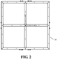
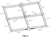
- the framework 10 has a grid shape with four square hollow cavities, and has an omnidirectional symmetry with respect to three axes of x, y and z, where a coordinate system o-xyz is defined as shown in FIG. 2 and FIG. 3 .
- a x-axis and a y-axis lie in a plane of the framework 10, the z-axis is perpendicular to a o-xy plane and forms a right-hand coordinate system together with the x-axis and the y-axis.
- the framework 10 is formed by connecting and assembling two set of square tubes, wherein the first set of square tubes include eight rims 10-1 located at edges of the framework 10 and the second set of square tubes include four keels 10-2 at the center of the framework 10; a cross structure is formed by the four keels 10-2 through a cross joint; the eight rims 10-1 are represented as rims I to VIII, respectively.
- Four L-shaped structures are formed by the eight rims 10-1, with each of the four L-shaped structures being formed by two of the eight rims through an L-shaped joint.
- the symmetrical grid-shaped framework is formed by connecting, via T-shaped joints, the four L-shaped structures with the cross structure formed by the four keels.
- each of the keels 10-2 and the rims 10-1 is formed by laying-up a carbon fiber composite material, and a layup pattern is [ ⁇ 45/0/ ⁇ 45] 2S ;
- the cross joint, the L-shaped joint and the T-shaped joint are all formed by using titanium alloy material of high specific strength and low thermal expansion coefficient; and the corresponding joint is bonded to each of the framework 10-1 and keel 10-2 by adhesive.
- a L-shaped angular piece 10-3 is also bonded at eight corners of the framework 10 using a structural adhesive, wherein the angular piece 10-3 is made of polyimide insulating material, is used to reinforce assembly connection of the framework 10 and have an insulation function.
- Each of the upper cover plate 11 and the lower cover plate 12 is a sandwich structure comprising an upper skin, a sandwiched plate, and a lower skin.
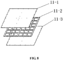
- the sandwich structure includes: from top to bottom, the upper skin 11-1, the sandwiched plate 11-2 and the lower skin 11-3, wherein the upper skin 11-1 and the sandwiched plate 11-2 are connected by an adhesive, and the thickness of the thereby formed adhesive layer is controlled within a range of 0.1 mm to 0.2 mm; the lower skin 11-3 and the sandwiched plate 11-2 are connected by an adhesive, and the thickness of the thereby formed adhesive layer is controlled within a range of 0.1mm-0.2mm.
- the sandwiched plate 11-2 is in a form of a rib mesh, where each of the upper skin 11-1 and the lower skin 11-3 is in a form of a panel, and the upper skin 11-1 and the lower skin 11-3 are identical in structures and materials;
- each of the upper skin 11-1, the sandwiched plate 11-2 and the lower skin 11-3 is made of carbon fiber composite material, and a layup pattern of the upper skin 11-1 and the lower skin 11-3 is [0/ ⁇ 45/90/+45] S ; and a layup pattern of the sandwiched plate 11-2 is [0/ ⁇ 45/90/0] 2S .
- the upper cover plate 11 and the lower cover plate 12 are provided with a plurality of circular exhaust holes disposed in a regular arrangement, and the circular exhaust holes are configured as an exhaust passage for gas inside the structure in a technical process and in a vacuum environment.
- the four power source modules can use a lithium battery, and more preferably, a solid state lithium battery.
- the four power source modules include a power source module I 20, a power source module II 21, a power source module III 22 and a power source module IV 23.
- each of the power source modules is embedded in the closed square hollow cavities formed by the framework 10, the upper cover plate 11 and the lower cover plate 12.
- Each of the closed square hollow cavities is provided only with one of the power source modules.
- the elastic support includes an elastic block 30 and an elastic cushion 31; and positive and negative wires of the power source module are extended out of the framework 10 via strong electrical cables and connected to a strong electrical connector 24 disposed on an outer wall of the framework 10 to form a charge/discharge interface; the power source module both has a function of charging for many times and discharging for many times, and functions as an oscillator to dissipate vibration energy.
- a plurality of voltage detection lines are extended out from the power source module, and welded to an electrical connector 33 mounted on the outer wall of the framework 10, to form a detection interface for detecting a graded voltage signal of each of the power source modules.
- the power source module can be further connected to an external power source management unit to achieve constant current charge/discharge or constant voltage charge/discharge with a controllable charge/discharge speed, so as to effectively manage the electric energy.
- the elastic block 30 is disposed between the periphery of each of the power source modules and a wall of the square hollow cavity, for accommodating the power source module;
- the elastic cushion 31 is disposed between the bottom surface of each of the power source modules and the lower cover plate 12 and between the top surface of each of the power source modules and the upper cover plate 11.
- the power source module, the elastic block 30 and the elastic cushion 31 constitute the vibration reduction system functioning as a 'spring-vibrator' model.
- the elastic block 30 and the elastic cushion 31 function as the elastic support with a certain rigidity and damping, and the power source modules function as a vibrator with a certain quality.
- a deformation of the elastic support enables the vibration reduction system to absorb vibration and consume energy, and the power source modules functioning as the vibrator converts structural vibrational energy into kinetic energy of the vibrator to consume the vibrational energy.
- the combined effect of the vibration reduction system and the power source modules reduces the transmission of the vibration in the multi-functional structure and effectively manages the mechanical environment of the power source module.
- Each of the elastic block 30 and the elastic cushion 31 is a made of high molecular elastic vinyl-terminated polydimethylsiloxane material, the chemical formula of the material is:
- Each of the elastic block 30 and the elastic cushion 31 both has a function of supporting the power source module, and has a function of dissipating a part of the vibration energy by the elastic deformation thereof, thereby having a function of protecting the power source module, and a function of insulating the power source module from the main structure module and cooling the power source module.
- the elastic block 30 is in a rectangular shape and both ends of the elastic block 30 are in surface contact with an inner side surface of the framework 10 and an outer side surface of the power source module without a fixed connection.
- the elastic cushion 31 is in a well shape, one surface of the elastic cushion is adhered to a lower surface of the upper cover plate 11 and an upper surface of the lower cover plate 12 by adhesive, and the other surface thereof is only in surface contact with the surface of the power source module without a fixed connection.
- Each of the elastic block 30 and the elastic cushion 31 is in the pre-compressed state after the installation, and have a supporting function, so that the power source module is kept in the framework 10 in a stationary state.
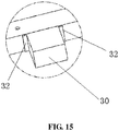
- a position limiting block 32 is adhered at a boundary between the inner wall of the framework 10 and each of the ends of both sides of each of the elastic blocks 30 using the structural adhesive for limiting the position of the elastic block 30.
- the sensor module comprises a plurality of temperature sensors and a plurality of acceleration sensors.
- the temperature sensors are disposed at an inner cavity and an outer sidewall of the power source module and are configured for monitoring temperature of the power source module.
- the acceleration sensors are disposed at an inner wall of the framework 10, an inner wall of the upper cover plate 11 and an inner wall of the lower cover plate 12 and are configured for measuring the vibration of the framework 10, the upper cover plate 11 and the lower cover plate 12, thus detecting and monitoring the internal electrical energy and vibration management of the multi-functional structure.
- a copper frame 50 is attached on the upper surface of the upper cover plate 11, and each of four corners of the copper frame 50 is connected to a grounding pile 53.
- One end of the grounding pile 53 is connected to a ground line of the power source module and the other end of the grounding pile 53 is connected to external ground, such as the ground of a system structure of a spacecraft.
- a bottom copper foil 51 is attached on the entire surface of the bottom surface of the lower cover plate 12.
- a U-shaped copper foil 52 is uniformly attached on the outer wall of the framework 10, where the U-shaped copper foil 52 is connected with the copper frame (50) and the bottom copper foil 51.
- a multi-functional structure for electrical energy and mechanical environmental management has functions of bearing, vibration reduction, energy storage, measurement and the like.
- the multi-functional structure for electrical energy and mechanical environment management has many functions such as bearing, vibration reduction, power supply, storage and data measurement, is used for a certain type of spacecraft, and has an ability of anti-shock and vibration.
- the multi-functional structure will be described in detail below in conjunction with an assembly process.
- Step 1 a framework is assembled.
- the overall shape and structure of the framework are shown in FIG. 2 and FIG. 3 .
- the framework is formed by connecting and assembling square tubes that is made by laying-up M40J/TDE-86 carbon fiber composite material.
- the square tubes have a cross-sectional size of 30mm ⁇ 25mm and a wall thickness of 2.5mm.
- the specific layup pattern is shown in Table 1 below.
- the square tubes consisting of the framework can be divided into two types: the rims located at edges of the framework and the keels at the center of the framework.
- a cross structure is formed by a total of four keels through a cross joint; a total of eight rims are represented as rims I to VIII, respectively; where four L-shaped structures are formed by the eight rims, with each of the four L-shaped structures being formed by two of the eight rims through an L-shaped joint; and a symmetrical grid-shaped framework is formed through T-shaped joints by the four L-shaped structures along with the cross structure formed by the four keels, where the outer envelope size of the grid-shaped framework is 800mm ⁇ 800mm ⁇ 25mm.
- the three shapes of joints used are shown in FIGS. 4-6 .
- Step 2 upper and lower cover plates are manufactured.
- the outer envelope size of the upper cover plate and the lower cover plate are both 800mm ⁇ 800mm ⁇ 5mm, and each of the upper cover plate and the lower cover plate is a sandwich structure comprising an upper skin, a sandwiched plate, and a lower skin.
- the thickness of the upper skin and the lower skin are 0.96mm.
- the sandwiched plate is in a form of a composite bar with a thickness of 3 mm, as shown in FIGS. 8 and 9 .
- the upper skin, the sandwiched plate and the lower skin are connected by gluing.
- J47 film is used as the adhesive.
- the circular exhaust holes are disposed in a regular manner on the surface.
- Step 3 the lower cover plate is bonded with the framework.
- the lower cover plate and the framework in the step 1 are bonded together using a J133 structural adhesive to form an integrated structure.
- Step 4 the lower cover plate is bonded with the elastic cushion.
- the elastic cushion is made of K216 silicone rubber material, its structure appearance is in a well shape, as shown in Figure 10 .
- Material systems, structure size and performance parameters of the elastic cushion are shown in Table 3.
- Table 3 elastic cushion of the relevant parameters Component Material System Hardness /A Layup Pattern Thickness mm
- the four elastic cushions are sequentially bonded to the lower cover plate using J133 adhesive.
- Step 5 a power source module is mounted.
- the multi-functional structure contains a total of four power source modules, respectively, recorded as the power source module I , II, III, IV.
- two power source modules adjacent to each other are connected in series to obtain two groups of power sources of the same output voltage, which are respectively referred to as a main power source and a backup power source.
- different numbers of power source modules for example, three or four
- DC voltages of different sizes can also be combined in series to obtain DC voltages of different sizes.
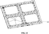
- the size of the outer envelope of the power source module is 300 mm ⁇ 280 mm ⁇ 20 mm, the overall shape is shown in FIG. 11 and FIG. 12 .
- the four power source modules are installed in the four square cavities formed by the grid shaped framework and the cover plate, and the lower surface of the power source module is in surface contact with the elastic cushion.
- the overall schematic diagram of the four power source modules installed in the framework is shown in FIG. 12 .
- the positive and negative lines of the main/backup power source are extended from slots at the sides of the main/backup power source and are connected to a 5-core strong electrical connector via a C55/0812-18 cable (in this embodiment, a 5-core strong electrical connector produced by Airbon company and having a model specification of MM-2F2-005-P13-2200-ZLP may be employed).
- a strong electrical connector is disposed on the outer wall of the framework to form a charge/discharge interface for the main/backup power source.
- a set of voltage detection lines are extended out from the power source module for detecting a graded voltage signal of each of the power source modules.
- the voltage detection lines are connected by a cable and welded to a 15-core electrical connector (in this embodiment selects, a 15-core electrical connector produced by Guizhou Aerospace Electric Company and having a model specification of J30JHT15TJSAN01 may be employed), and the electrical connector is also mounted on the outer wall of the framework.
- Step 6 an elastic block is mounted.
- the elastic block is also made of K216 silicone rubber.
- the elastic block is in a rectangular shape and having a structure as shown in FIG. 13 and FIG. 14 , and the material system, structure size and performance parameters thereof are shown in Table 4.
- Table 4 the relevant parameters of the elastic block Component Material System Hardness/A Shape and Size Thickness mm
- the four sides of the power source module each are connected in surface with the framework via the elastic blocks.
- the position limiting block is made of T300/E648 fiber fabric layup material and has a size of 10 mm ⁇ 5 mm ⁇ 2 mm, and is used to limit the position of the elastic block.
- each of the elastic blocks is in the pre-compressed state and the power source module cannot move inside the framework.
- the power source module is connected to the main bearing structure via the elastic block and via the elastic cushion to form the vibration reduction system.
- the vibration reduction module has two functions: to manage the mechanical environment of the internal power source module so as to protect the power source module; and to dissipate the vibration energy through the deformation of the elastic material so as to reduce the transmission of the vibration in the structure.
- the principle of vibration reduction is shown in FIG. 16 .
- the power source module of the present invention is equivalent to a vibration reduction element in the figure, i.e., the oscillator having the mass m 2 , and the elastic support corresponds to a spring with a stiffness k and a damper with a damping coefficient c.
- m 1 represents the mass of the entire multi-functional structure for the electrical energy and mechanical management
- ⁇ represents the natural angular frequency of vibration
- the mass m 2 of the vibration reduction element and the stiffness k of the elastic support may be properly chosen such that k- ⁇ 2 m 2 ⁇ 0, then the vibration of the structure x 1 ⁇ 0, x 2 ⁇ 0, that is, the vibration will be borne by the vibration reduction element, therebt attenuating the vibration by damping characteristics of the vibration reduction element.
- Step 7 a sensor is bonded.
- the sensor includes a temperature sensor and a acceleration sensor, so as to obtain the internal temperature and acceleration signals of the structure.
- the specific installation positions of the temperature sensor and the acceleration sensor are as shown in FIG. 17 .
- Table 5 the model and number of internal sensors Sensor Name Sensor Model Number Corresponding Number in the Figure Temperature Sensor MF501 8 WDC01 ⁇ WDC08 Acceleration Sensor PCB352A21 8 JSDC01 ⁇ JSDC08
- the corresponding number of the temperature sensors in the figure are WDC01-WDC08.
- the temperature sensors numbered as WDC01, WDC03, WDC05 and WDC07 are bonded to the side wall of the outer surface of the power source modules, and the temperature sensors numbered as WDC02, WDC04, WDC06 and WDC08 are bonded to the inner cavity of the power source modules.
- the sensor is connected to the outside via the electrical connector.
- a GD414 silicon rubber is used to fix a head of the temperature sensor.
- the lead of the temperature sensor are extended out from the side of the power source module and are disposed at the upper surface of the power source module, and are connected to a 9-core weak electrical connector (produced by Guizhou Aerospace Electric Company and the model is J30JH) as the detection interface via C55/0114-26 wires.
- a 9-core weak electrical connector produced by Guizhou Aerospace Electric Company and the model is J30JH
- the corresponding number of the acceleration sensors in the figure are JSDC01 ⁇ JSDC08, and the installation positions thereof are located on the inner walls of the framework and the inner surfaces of the cover plate, wherein six acceleration sensors are disposed at the inner walls of the framework, one acceleration sensor is disposed at an inner surface of the upper cover plate and one acceleration sensor is disposed at an inner surface of lower cover plate.
- an acceleration sensor numbered as JSDC01 is mounted on the inner wall of the border V
- an acceleration sensor numbered as JSDC02 is mounted on the inner wall of the border IV
- an acceleration sensor numbered as JSDC03 is mounted on the upper surface of the lower cover plate
- an acceleration sensor numbered as JSDC04 is mounted on the lower surface of the upper cover plate
- an acceleration sensor numbered as JSDC05 is mounted on the inner wall of the border I
- an acceleration sensor numbered as JSDC06 is mounted on the inner wall of the framework VIII
- an acceleration sensor numbered as JSDC07 is mounted on the inner wall of the framework IV
- an acceleration sensor numbered as JSDC08 is mounted on the inner wall of the framework VIII.
- the insulating sheet is bonded with J133 adhesive, and then the acceleration sensors are bonded to the insulating sheet via the J133 adhesive, so as to ensure that shell of the installed acceleration sensors is completely insulated from the body of the multi-functional vibration reduction structure.
- the leads of the acceleration sensors are connected to a 9-core electrical connector (produced by Guizhou Aerospace Electric Company and the model is J30JH) via C55/0114-26 wires.
- Step 8 the upper cover plate is bonded with the elastic cushion.
- the upper cover plate and the elastic cushion are bonded together also using the J133 structural adhesive to form an integrated structure.
- Step 9 the upper cover plate is mounted.
- the screw mounting holes are disposed at the four angular points of the framework, the center position of the framework, the rims and the keels.
- the upper cover plate is fastened to the framework by structural mounting screws made of titanium alloy TC-4R and corresponding flat washers and spring washers, thus forming a complete multi-functional structure for electrical energy and mechanical environmental management.
- the schematic diagram of the assembled framework is shown in FIG. 20 .
- the elastic cushion is also in the pre-compressed state, and the power source module cannot move inside the framework.
- Step 10 a conductive copper foil and a grounding pile are mounted.
- the upper surface of the upper cover plate and the lower surface of the lower cover plate are both polished. Then, a copper frame is attached on the upper surface of the upper cover plate (as shown in FIG. 18 ), and a bottom copper foil is attached entirely on the bottom surface of the lower cover plate (in this embodiment, the bottom copper foil is formed by splicing a plurality of copper foils with a width of 50 mm so as to form an entire conductive surface, as shown in FIG. 19 ).
- the U-shaped copper foil is uniformly attached on the outer wall of the framework. The U-shaped copper foil is connected to the copper frame and the bottom copper foil (as shown in FIG. 20 ).
- each of the four corners of the copper frame is connected to a grounding pile (as shown in FIG. 20 ), where one end of the grounding pile is connected to the ground line of the power source module and the other end of the grounding pile is connected to the system of the spacecraft.
- the multi-functional structure for electrical energy and mechanical environment management functions as a structure with a carrying function to directly replace an original spacecraft deck, and can also function as a bearing structure in a spacecraft capsule.
- the multi-functional structure according to the present invention directly replaces an original spacecraft deck, and a schematic diagram thereof is shown in FIG. 21 .
- an acceleration response test is carried out under ground conditions.
- the border of the multi-functional structure is beaten by a force hammer at a point A in the X-axis direction and a point B in the Y-axis direction respectively, and a response signal from the acceleration sensor is acquired by a test computer.
- Acceleration signals from the acceleration sensors 1 (JSDC01) and 5 (JSDC05) are obtained when the border is beaten in the X direction and are shown in FIG. 22 .
- Acceleration signals from the acceleration sensors 2 (JSDC02) and 6 (JSDC06) are obtained when the border is beaten in the Y direction and are shown in FIG. 23 .
- a signal peak of the acceleration sensor 1 is significantly larger than a signal peak of the acceleration sensor 5, and a signal peak of the acceleration sensor 2 is significantly larger than a signal peak of the acceleration sensor 6. Therefore, the vibrations generated by the beat are significantly attenuated after passing through the multi-functional structure.
- the multi-functional structure for electrical energy and mechanical environment management is a structure that has the functions of bearing, vibration reduction, electrical energy storage and measurement, and the like, and the requirement of light in weight and miniaturization in volume of the structure can be realized.
Landscapes
- Engineering & Computer Science (AREA)
- Remote Sensing (AREA)
- Aviation & Aerospace Engineering (AREA)
- Chemical & Material Sciences (AREA)
- Chemical Kinetics & Catalysis (AREA)
- Electrochemistry (AREA)
- General Chemical & Material Sciences (AREA)
- Physics & Mathematics (AREA)
- General Engineering & Computer Science (AREA)
- Acoustics & Sound (AREA)
- Manufacturing & Machinery (AREA)
- General Physics & Mathematics (AREA)
- Mechanical Engineering (AREA)
- Health & Medical Sciences (AREA)
- Life Sciences & Earth Sciences (AREA)
- Biodiversity & Conservation Biology (AREA)
- Environmental & Geological Engineering (AREA)
- Environmental Sciences (AREA)
- General Health & Medical Sciences (AREA)
- Toxicology (AREA)
- Astronomy & Astrophysics (AREA)
- Vibration Prevention Devices (AREA)
- Combustion & Propulsion (AREA)
Claims (10)
- Multifunktionsstruktur für eine Verwaltung von elektrischer Energie und mechanischer Umgebung, welches ein Hauptstrukturmodul, vier wiederaufladbare / entladbare Stromquellenmodule, ein Schwingungsverminderungssystem und ein Sensormodul aufweist;wobei das Hauptstrukturmodul einen Rahmen (10), eine obere Abdeckplatte (11) und eine untere Abdeckplatte (12) aufweist; wobei das Rahmen (10) eine Gitterform mit vier quadratischen Hohlräumen aufweist und es eine omnidirektionale Symmetrie in Bezug auf drei Achsen von x, y und z aufweist; wobei die untere Abdeckplatte (12) an einer unteren Oberfläche des Rahmens (10) befestigt ist; wobei die obere Abdeckplatte (11) an einer oberen Oberfläche des Rahmens (10) befestigt ist; wobei der Rahmen (10), die obere Abdeckplatte (11) und die untere Abdeckplatte (12) eine Hauptlagerstruktur bilden, um eine Lagerfunktion zu haben;wobei die vier Stromquellenmodule ein Stromquellenmodul I (20), ein Stromquellenmodul II (21), ein Stromquellenmodul III (22) und ein Stromquellenmodul IV (23) umfassen; wobei mittels eines elastischen Trägers die Stromquellenmodule in die Hohlräume eingebettet sind, die durch den Rahmen (10), die obere Abdeckplatte (11) und die untere Abdeckplatte (12) gebildet werden, und jedes der geschlossenen quadratischen Hohlräume mit einem der Stromquellenmodule versehen ist; wobei der elastische Träger einen elastischen Block (30) und ein elastisches Kissen (31) aufweist; und wobei positive und negative Drähte des Stromquellenmoduls über starke elektrische Kabel aus dem Rahmen (10) herausgeführt werden und mit einem starken elektrischen Verbinder (24) verbunden sind, der an einer äußeren Wand des Rahmens (10) angeordnet ist, um eine Lade- / Entladeschnittstelle zu bilden; wobei das Stromquellenmodul sowohl die Funktion des mehrmaligen Ladens als auch des mehrmaligen Entladens und auch die Funktion eines Oszillators zum Ableiten von Schwingungsenergie hat,wobei der elastische Block (30) zwischen einem Umfang von jedem der Stromquellenmodule und einer Wand des quadratischen Hohlraums zur Aufnahme des Stromquellenmoduls angeordnet ist; wobei das elastische Kissen (31) zwischen der unteren Oberfläche von jedem der Stromquellenmodule und der unteren Abdeckplatte (12) und zwischen der oberen Oberfläche von jedem der Stromquellenmodule und der oberen Abdeckplatte (11) angeordnet ist;wobei die Stromquellenmodule, der elastische Block (30) und das elastische Kissen (31) das Schwingungsverminderungssystem bilden, das als ein "Feder-Vibrator"-Modell wirkt, wobei der elastische Block (30) und das elastische Kissen (31) als die elastische Unterstützung mit einer bestimmten Steifheit und einer bestimmten Dämpfung wirken, und die Stromquellenmodule als ein Vibrator mit einer bestimmten Qualität wirken; wobei eine Verformung des elastischen Trägers es dem Schwingungsverminderungssystem ermöglicht, Schwingungen zu absorbieren und Energie zu verbrauchen, und wobei die Stromquellenmodule, die als der Vibrator wirken, strukturelle Schwingungsenergie in kinetische Energie des Vibrators umwandeln, um die Schwingungsenergie zu verbrauchen, so dass eine kombinierte Wirkung des Schwingungsverminderungssystems und der Stromquellenmodule die Übertragung der Schwingung in der multifunktionalen Struktur verringert und effektiv die mechanische Umgebung des Stromquellenmoduls verwaltet; undwobei das Sensormodul eine Vielzahl an Temperatursensoren und eine Vielzahl an Beschleunigungssensoren aufweist; wobei die Temperatursensoren an einem inneren Hohlraum und einer äußeren Seitenwand des Stromquellenmoduls angeordnet sind und zum Überwachen der Temperatur des Stromquellenmoduls ausgestaltet sind; wobei die Beschleunigungssensoren an einer inneren Wand des Rahmens (10), einer inneren Wand der oberen Abdeckplatte (11) und einer inneren Wand der unteren Abdeckplatte (12) angeordnet sind und zur Messung der Schwingung des Rahmens (10), der oberen Abdeckplatte (11) und der unteren Abdeckplatte (12) ausgestaltet sind, und somit die Verwaltung der internen elektrischen Energie und der Schwingungen der multifunktionalen Strukturen erfassen und überwachen.
- Multifunktionsstruktur für die Verwaltung von elektrischer Energie und mechanischer Umgebung nach Anspruch 1, wobeider Rahmen (10) durch ein Verbinden von zwei Sätzen an Vierkantrohren zusammengebaut wird, wobei der erste Satz der Vierkantrohre acht Ränder (10-1), die an den Rändern des Rahmens (10) angeordnet sind, und der zweite Satz der Vierkantrohre vier Kiele (10-2) aufweist, die in der Mitte des Rahmens (10) angeordnet sind; wobeieine Kreuzstruktur durch die vier Kiele (10-2) durch eine Kreuzverbindung gebildet worden ist; wobeivier L-förmige Strukturen durch die acht Ränder (10-1) gebildet worden sind, wobei jede der vier L-förmigen Strukturen durch jeweils zwei der acht Ränder durch eine L-förmige Verbindung gebildet worden ist; und wobeiein symmetrischer gitterförmiger Rahmen gebildet worden ist, indem die vier L-förmigen Strukturen durch die T-förmigen Verbindungen mit der Kreuzstruktur verbunden worden sind.
- Multifunktionsstruktur für die Verwaltung von elektrischer Energie und mechanischer Umgebung nach Anspruch 2, wobeijeder der Kiele (10-2) und der Ränder (10-1) durch ein Anlegen eines Kohlefaserverbundmaterials gebildet worden ist, und ein Anlegemuster [±45/0/±45]2S ist; wobeidie Kreuzverbindung, die L-förmige Verbindung und die T-förmige Verbindung aus einem Titanlegierungsmaterial mit einer hohen spezifischer Festigkeit und einem geringen Wärmeausdehnungskoeffizienten bestehen; und die entsprechende Verbindung mit jedem von dem Rahmen (10-1) und dem Kiel (10-2) mit einem Klebstoff verbunden ist.
- Multifunktionsstruktur für die Verwaltung von elektrischer Energie und mechanischer Umgebung nach Anspruch 2, wobeiein L-förmiges Winkelstück (10-3) ebenfalls an jeder der Ecken des Rahmens (10) unter Verwendung eines strukturellen Klebstoffs befestigt worden ist, das Winkelstück (10-3) aus einem Polyimid-Isoliermaterial besteht und es zur Verstärkung des Zusammenbaus verwendet wird und eine Verbindung des Rahmens (10) eine Isolationsfunktion aufweist; und wobeieine Isolierschicht (10-4) mit der Montageposition des Beschleunigungssensors verbunden ist, wobei die Isolierschicht (10-4) aus dem Polyimid-Isoliermaterial hergestellt worden ist, um den Beschleunigungssensor von dem Hauptstrukturmodul zu isolieren.
- Multifunktionsstruktur für die Verwaltung von elektrischer Energie und mechanischer Umgebung nach Anspruch 1, wobeidie obere Abdeckplatte (11) und die untere Abdeckplatte (12) jeweils eine Sandwichstruktur sind; wobeidie Sandwichstruktur von oben nach unten aufweist: eine obere Haut (11-1), eine sandwichartig angeordnete Platte (11-2) und eine untere Haut (11-3), wobei die obere Haut (11-1) und die sandwichartig angeordnete Platte (11-2) durch einen Klebstoff verbunden sind und eine Dicke der dadurch gebildeten Klebstoffschicht auf eine solche Weise gesteuert ist, dass sie in einem Bereich von 0,1 mm bis 0,2 mm liegt; wobei die untere Haut (11-3) und die sandwichartig angeordnete Platte (11-2) durch einen Klebstoff verbunden sind, und die Dicke der dadurch gebildeten Klebstoffschicht eine solche Weise gesteuert ist, dass sie in einem Bereich von 0,1 mm bis 0,2 mm liegt; wobeidie sandwichartig angeordnete Platte (11-2) die Form eines Rippennetzes hat, die obere Haut (11-1) und die untere Haut (11-3) jeweils die Form einer Platte haben und die obere Haut (11-1) und die untere Haut (11-3) in Struktur und Material identisch sind; und wobeidie obere Haut (11-1), die sandwichartig angeordnete Platte (11-2) und die untere Haut (11-3) jeweils aus einem Kohlefaserverbundmaterial hergestellt worden sind und ein Anlegemuster der oberen Haut (11-1) und der unteren Haut (11-3) [0/±45/90/±45]s ist; und ein Anlegemuster der sandwichartig angeordneten Platte (11-2) [0/±45/90/0]2S ist.
- Multifunktionsstruktur für die Verwaltung von elektrischer Energie und mechanischer Umgebung nach Anspruch 1, wobeidie obere Abdeckplatte (11) und die untere Abdeckplatte (12) mit einer Vielzahl an kreisförmigen Auslasslöchern versehen sind, die in einer regelmäßigen Anordnung angeordnet sind, und die kreisförmigen Auslasslöcher ausgestaltet sind, um das Gas innerhalb der multifunktionalen Struktur in einem technischen Verfahren und das Gas innerhalb der multifunktionalen Struktur in einer Vakuumumgebung auszulassen; und wobeidie untere Abdeckplatte (12) durch ein Kleben an der unteren Oberfläche des Rahmens (10) befestigt worden ist; wobei die obere Abdeckplatte (11) an der oberen Oberfläche des Rahmens (10) durch eine Gewindeverbindung angeschraubt worden ist, und die Schraubenbefestigungslöcher sich an vier Winkelpunkten des Rahmens (10) befinden, einer mittleren Position des Rahmens (10)), der Ränder und der Kiele des Rahmens (10); wobei die Schraube aus einem Titanlegierungsmaterial mit einem kleinen Wärmeausdehnungskoeffizienten besteht, das für große Temperaturänderungen und dramatische Änderungen in einer Arbeitsumgebung geeignet ist.
- Multifunktionsstruktur für die Verwaltung von elektrischer Energie und mechanischer Umgebung nach Anspruch 1, wobei
der elastische Block (30) und das elastische Kissen (31) aus einem hochmolekularen elastischen Polydimethylsiloxanmaterial mit einem endständigen Vinyl hergestellt worden sind, dessen chemische Formel lautet:
- Multifunktionsstruktur für die Verwaltung von elektrischer Energie und mechanischer Umgebung nach Anspruch 1, wobeider elastische Block (30) und das elastische Kissen (31) auf eine vorkomprimierte Weise angebracht worden sind, um eine elastische Beschränkungsunterstützung für das Stromquellenmodul durch ein Erzeugen einer elastischen Kraft auf der Grundlage einer vorkomprimierten Kraft zu erzielen; wobei der elastische Block (30) eine rechteckige Form aufweist und beide Enden des elastischen Blocks (30) in einem Oberflächenkontakt mit einer inneren seitlichen Oberfläche des Rahmens (10) und mit einer äußeren seitlichen Oberfläche des Stromquellenmoduls ohne eine feste Verbindung stehen; wobei das elastische Kissen (31) sich in einer guten Form befindet, eine Oberfläche des elastischen Kissens an einer unteren Oberfläche der oberen Abdeckplatte (11) und einer oberen Oberfläche der unteren Abdeckplatte (12) durch einen Klebstoff angeklebt worden ist, und die andere Oberfläche davon nur in einem flächigem Kontakt mit der Oberfläche des Stromquellenmoduls ohne eine feste Verbindung steht, und wobeisowohl der elastische Block (30) als auch das elastische Kissen (31) sich nach dem Einbau in einem vorkomprimierten Zustand befinden.
- Multifunktionsstruktur für die Verwaltung von elektrischer Energie und mechanischer Umgebung nach Anspruch 1, wobei
ein Positionsbegrenzungsblock (32) an einer Grenze zwischen der inneren Wand des Rahmens (10) und jedem der Enden beider Seiten jedes der elastischen Blöcke (30) durch einen Strukturklebstoff verklebt worden ist, und der Positionsbegrenzungsblock (32) ausgestaltet, um die Position des elastischen Blocks (30) zu begrenzen, um eine Bewegung und eine Verschiebung des elastischen Blocks (30) zu vermeiden. - Multifunktionsstruktur für die Verwaltung von elektrischer Energie und mechanischer Umgebung nach einem der Ansprüche 1 bis 9, wobeidas Stromquellenmodul eine Lithiumbatterie ist und / oder wobeieine Vielzahl an Spannungserfassungsleitungen sich aus dem Stromquellenmodul heraus erstrecken und mit einem elektrischen Verbinder (33) verschweißt worden sind, der an der äußeren Wand des Rahmens (10) angebracht worden ist, um eine Erfassungsschnittstelle zum Erfassen eines abgestuften Spannungssignals von jedem von beiden der Stromquellenmodule zu bilden; und / oder wobeidie obere Oberfläche der oberen Abdeckplatte (11) und die untere Oberfläche der unteren Abdeckplatte (12) jeweils poliert worden sind, um die Oberfläche der Kohlenstofffaser der gesamten multifunktionalen Struktur in Bezug auf die Leitfähigkeit gleichbleibend zu machen; wobeiein Kupferrahmen (50) an der oberen Oberfläche der oberen Abdeckplatte (11) angebracht worden ist; eine untere Kupferfolie (51) auf der gesamten Oberfläche der unteren Oberfläche der unteren Abdeckplatte (12) angebracht worden ist, wobei die untere Kupferfolie (51) durch ein Spleißen einer Vielzahl an Kupferfolien einer bestimmten Breite gebildet worden ist, um eine vollständig leitende Oberfläche zu bilden; wobeieine U-förmige Kupferfolie (52) an der äußeren Wand des Rahmens (10) gleichmäßig angebracht worden ist, wobei die U-förmige Kupferfolie (52) mit dem Kupferrahmen (50), der sich auf der oberen Abdeckplatte (11) befindet, und der unteren Kupferfolie (51), die sich auf der unteren Abdeckplatte (12) befindet, verbunden worden ist, um die multifunktionale Struktur für das Management der elektrischen Energie und der mechanischen Umgebung in Bezug auf die Leitfähigkeit als Ganzes konsistent zu machen; und wobeian jeder an der vier Ecken des Kupferrahmens (50) ein Erdungsstift (53) angebracht worden ist, wobei ein Ende des Erdungsstifts (53) mit einer Erdungsleitung des Stromquellenmoduls und das andere Ende des Erdungsstifts (53) mit der Außenmasse verbunden worden ist, so dass die Multifunktionsstruktur als ein Ganzes durch den Erdungsstift (53) wirksam geerdet wird.
Applications Claiming Priority (2)
| Application Number | Priority Date | Filing Date | Title |
|---|---|---|---|
| CN201610307086.1A CN105947235B (zh) | 2016-05-10 | 2016-05-10 | 电能与力学环境管理多功能结构 |
| PCT/CN2016/000380 WO2017193228A1 (zh) | 2016-05-10 | 2016-07-12 | 电能与力学环境管理多功能结构 |
Publications (3)
| Publication Number | Publication Date |
|---|---|
| EP3330188A1 EP3330188A1 (de) | 2018-06-06 |
| EP3330188A4 EP3330188A4 (de) | 2019-01-16 |
| EP3330188B1 true EP3330188B1 (de) | 2020-02-19 |
Family
ID=56915043
Family Applications (1)
| Application Number | Title | Priority Date | Filing Date |
|---|---|---|---|
| EP16901184.8A Active EP3330188B1 (de) | 2016-05-10 | 2016-07-12 | Multifunktionelle struktur zur verwaltung von elektrischer energie und mechanischer umgebung |
Country Status (4)
| Country | Link |
|---|---|
| US (1) | US10882641B2 (de) |
| EP (1) | EP3330188B1 (de) |
| CN (1) | CN105947235B (de) |
| WO (1) | WO2017193228A1 (de) |
Families Citing this family (13)
| Publication number | Priority date | Publication date | Assignee | Title |
|---|---|---|---|---|
| CN105955075B (zh) * | 2016-05-10 | 2017-03-22 | 中国人民解放军国防科学技术大学 | 航天器在轨多功能结构综合管理与操控系统 |
| CN106564620B (zh) * | 2016-11-14 | 2019-03-29 | 中国科学院上海微系统与信息技术研究所 | 卫星壳体板和卫星壳体 |
| CN106915474B (zh) * | 2017-01-20 | 2018-12-21 | 北京空间飞行器总体设计部 | 一种轻量化碳纤维增强树脂复合材料加筋板壳主承力结构 |
| CN106784490B (zh) * | 2017-01-23 | 2023-04-07 | 湖北汽车工业学院 | 一种基于点阵结构的轻量化电池箱 |
| CN110350119B (zh) * | 2019-06-17 | 2024-03-08 | 清华大学苏州汽车研究院(相城) | 一种电池箱体及电池箱 |
| DE102019122812B4 (de) * | 2019-08-26 | 2024-03-14 | Sma Solar Technology Ag | Gehäuse für ein elektrisches gerät mit einem deckel und elektrisches gerät mit einem gehäuse |
| CN110781610A (zh) * | 2019-11-11 | 2020-02-11 | 中国工程物理研究院机械制造工艺研究所 | 一种适宜于焊接的板状结构轻量化设计方法及轻量化结构 |
| CN113054302B (zh) * | 2021-03-12 | 2022-06-14 | 中国人民解放军国防科技大学 | 具有减重和负压保护双重功能的航天器电池组件 |
| CN112688004B (zh) * | 2021-03-12 | 2021-06-04 | 中国人民解放军国防科技大学 | 一种胞元式航天多功能结构锂电池 |
| CN113060303B (zh) * | 2021-03-18 | 2022-07-29 | 中国人民解放军国防科技大学 | 一种含结构锂电池的一体化航天器舱板 |
| CN115347303B (zh) * | 2021-05-14 | 2025-10-03 | 中创新航科技集团股份有限公司 | 电池箱体及电池包、车辆 |
| CN115224413A (zh) * | 2022-06-28 | 2022-10-21 | 杭州卡涞复合材料科技有限公司 | 一种轻量化电池箱体 |
| CN118062256A (zh) * | 2024-04-15 | 2024-05-24 | 哈尔滨工业大学 | 一种平板式卫星构型 |
Family Cites Families (26)
| Publication number | Priority date | Publication date | Assignee | Title |
|---|---|---|---|---|
| DE4340007A1 (de) * | 1992-12-05 | 1994-06-09 | Volkswagen Ag | Aufnahme für eine Fahrzeugbatterie |
| JP4432168B2 (ja) * | 1998-11-30 | 2010-03-17 | ソニー株式会社 | 移動体搭載用バッテリ装置 |
| WO2005114811A2 (en) * | 2004-05-17 | 2005-12-01 | Railpower Technologies Corp. | Design of a large battery pack for a hybrid locomotive |
| US9653748B2 (en) * | 2005-04-14 | 2017-05-16 | Enerdel, Inc. | Apparatus and method for securing battery cell packs |
| US7875378B2 (en) * | 2006-03-06 | 2011-01-25 | Lg Chem, Ltd. | Voltage sensing member and battery module employed with the same |
| CA2873314C (en) * | 2007-01-12 | 2018-02-27 | Koehler-Bright Star, Inc. | Battery pack for miner's cap lamp with charging and discharging control module |
| US8212522B2 (en) * | 2008-02-12 | 2012-07-03 | Leah M. Piatkowski, legal representative | Energy storage module |
| US20100104927A1 (en) * | 2008-10-29 | 2010-04-29 | Scott Albright | Temperature-controlled battery configuration |
| JP5222335B2 (ja) * | 2010-09-22 | 2013-06-26 | 三菱重工業株式会社 | 電池モジュールおよび電池システム |
| WO2012067045A1 (ja) * | 2010-11-18 | 2012-05-24 | 三洋電機株式会社 | 組電池、組電池用セパレータ及びこれを備える車両 |
| JP5587167B2 (ja) * | 2010-12-27 | 2014-09-10 | 三洋電機株式会社 | 電源装置及び電源装置を備える車両並びに防塵ケース |
| JP2012221898A (ja) * | 2011-04-13 | 2012-11-12 | Sony Corp | 非水電解質電池および非水電解質、並びに電池パック、電子機器、電動車両、蓄電装置および電力システム |
| KR101469518B1 (ko) * | 2011-08-01 | 2014-12-05 | 주식회사 엘지화학 | 안전성이 향상된 전지모듈 |
| KR101283486B1 (ko) * | 2011-08-23 | 2013-07-12 | 주식회사 엘지화학 | 이차 전지의 안전성 향상 장치 및 방법 |
| JP5915311B2 (ja) * | 2012-03-27 | 2016-05-11 | 住友電気工業株式会社 | 蓄電装置 |
| JP2014199801A (ja) * | 2012-12-28 | 2014-10-23 | 株式会社半導体エネルギー研究所 | 非水系二次電池およびセパレータ |
| CN103107299B (zh) * | 2013-01-31 | 2015-07-22 | 中国海洋石油总公司 | 一种锂电池的保护结构 |
| KR102016754B1 (ko) * | 2013-02-05 | 2019-10-21 | 삼성에스디아이 주식회사 | 배터리 팩 |
| US9525195B2 (en) * | 2013-07-30 | 2016-12-20 | Johnson Controls Technology Corporation | Remanufacturing methods for battery module |
| US9831482B2 (en) * | 2013-09-06 | 2017-11-28 | Johnson Controls Technology Company | Battery module lid system and method |
| CN103490024B (zh) * | 2013-09-17 | 2015-09-09 | 东风汽车公司 | 一种集成式动力电池组件 |
| JP6311566B2 (ja) * | 2014-03-11 | 2018-04-18 | 株式会社村田製作所 | 電池パック、電子機器およびウェアラブル端末 |
| CN105006533B (zh) * | 2015-06-12 | 2017-07-18 | 东南大学 | 一种隔离式带减震结构的模块化动力电池组 |
| CN204793006U (zh) * | 2015-06-26 | 2015-11-18 | 广东新凌嘉新能源股份有限公司 | 一种锂电池模组 |
| CN204834785U (zh) * | 2015-08-17 | 2015-12-02 | 汕头市毅和电源科技有限公司 | 一种锂电池组 |
| CN105128644B (zh) * | 2015-09-29 | 2017-08-22 | 北京理工大学 | 一种分布式四轮轮毂电机驱动电动汽车的动力电池组的布置结构 |
-
2016
- 2016-05-10 CN CN201610307086.1A patent/CN105947235B/zh active Active
- 2016-07-12 WO PCT/CN2016/000380 patent/WO2017193228A1/zh not_active Ceased
- 2016-07-12 EP EP16901184.8A patent/EP3330188B1/de active Active
-
2017
- 2017-12-27 US US15/855,426 patent/US10882641B2/en active Active
Non-Patent Citations (1)
| Title |
|---|
| None * |
Also Published As
| Publication number | Publication date |
|---|---|
| CN105947235A (zh) | 2016-09-21 |
| WO2017193228A1 (zh) | 2017-11-16 |
| US10882641B2 (en) | 2021-01-05 |
| US20180118379A1 (en) | 2018-05-03 |
| EP3330188A1 (de) | 2018-06-06 |
| EP3330188A4 (de) | 2019-01-16 |
| CN105947235B (zh) | 2017-05-17 |
Similar Documents
| Publication | Publication Date | Title |
|---|---|---|
| EP3330188B1 (de) | Multifunktionelle struktur zur verwaltung von elektrischer energie und mechanischer umgebung | |
| CN110993845B (zh) | 电池包及电动车 | |
| KR102698904B1 (ko) | 절연 구조가 향상된 배터리 모듈 및 이를 포함하는 배터리 팩 | |
| JP5383745B2 (ja) | 電源装置 | |
| CN114335874B (zh) | 电池单元堆叠间隔物、电池、车辆和组装该堆叠的方法 | |
| JP2008235170A (ja) | リチウムイオン二次電池パック | |
| US11530026B2 (en) | Energy subsystems integrated into structural components of an aircraft | |
| JP6346084B2 (ja) | 電池パック | |
| CN116171508A (zh) | 电池模块和包括该电池模块的电池组 | |
| WO2012063640A1 (ja) | 電気二重層キャパシタ | |
| CN213782135U (zh) | 一种电池模组、电池包以及用电设备 | |
| CN112688004B (zh) | 一种胞元式航天多功能结构锂电池 | |
| CN110474130A (zh) | 一种上面级用锂离子电池组 | |
| CN116157949A (zh) | 电池模块及包括该电池模块的电池组 | |
| JP7819297B2 (ja) | バッテリーパック及びこれを含む自動車 | |
| WO2024261221A1 (en) | Thermal barrier component for battery assembly and battery assembly | |
| CN219086150U (zh) | 电池箱体、电池包及用电设备 | |
| CN222720573U (zh) | 储能壁板以及包括其的用电设备 | |
| CN223502035U (zh) | 一种电池装置和用电装置 | |
| CN221379614U (zh) | 一种电池包框架及电池包 | |
| CN223858353U (zh) | 箱盖、电池装置及用电设备 | |
| CN223023299U (zh) | 电池单体、电池及用电设备 | |
| CN224217663U (zh) | 电池包及用电装置 | |
| CN222927602U (zh) | 电池装置、用电装置及储能装置 | |
| CN222927643U (zh) | 电池及用电装置 |
Legal Events
| Date | Code | Title | Description |
|---|---|---|---|
| STAA | Information on the status of an ep patent application or granted ep patent |
Free format text: STATUS: THE INTERNATIONAL PUBLICATION HAS BEEN MADE |
|
| PUAI | Public reference made under article 153(3) epc to a published international application that has entered the european phase |
Free format text: ORIGINAL CODE: 0009012 |
|
| STAA | Information on the status of an ep patent application or granted ep patent |
Free format text: STATUS: REQUEST FOR EXAMINATION WAS MADE |
|
| 17P | Request for examination filed |
Effective date: 20180124 |
|
| AK | Designated contracting states |
Kind code of ref document: A1 Designated state(s): AL AT BE BG CH CY CZ DE DK EE ES FI FR GB GR HR HU IE IS IT LI LT LU LV MC MK MT NL NO PL PT RO RS SE SI SK SM TR |
|
| AX | Request for extension of the european patent |
Extension state: BA ME |
|
| RIN1 | Information on inventor provided before grant (corrected) |
Inventor name: YIN, CHANGPING Inventor name: LI, DEZHAN Inventor name: WU, JUN Inventor name: LI, DONGXU |
|
| A4 | Supplementary search report drawn up and despatched |
Effective date: 20181214 |
|
| RIC1 | Information provided on ipc code assigned before grant |
Ipc: H01M 10/052 20100101ALI20181210BHEP Ipc: F16F 15/02 20060101ALN20181210BHEP Ipc: H01M 2/02 20060101ALI20181210BHEP Ipc: B64G 1/40 20060101ALI20181210BHEP Ipc: B64G 1/42 20060101ALI20181210BHEP Ipc: H01M 2/10 20060101ALI20181210BHEP Ipc: B64G 1/66 20060101ALI20181210BHEP Ipc: B64G 1/22 20060101AFI20181210BHEP Ipc: H01M 10/48 20060101ALN20181210BHEP |
|
| DAV | Request for validation of the european patent (deleted) | ||
| DAX | Request for extension of the european patent (deleted) | ||
| GRAP | Despatch of communication of intention to grant a patent |
Free format text: ORIGINAL CODE: EPIDOSNIGR1 |
|
| STAA | Information on the status of an ep patent application or granted ep patent |
Free format text: STATUS: GRANT OF PATENT IS INTENDED |
|
| RIC1 | Information provided on ipc code assigned before grant |
Ipc: H01M 2/02 20060101ALI20191025BHEP Ipc: B64G 1/10 20060101ALI20191025BHEP Ipc: H01M 2/10 20060101ALI20191025BHEP Ipc: B64G 1/40 20060101ALI20191025BHEP Ipc: F16F 7/104 20060101ALI20191025BHEP Ipc: H01M 10/48 20060101ALN20191025BHEP Ipc: H01M 10/052 20100101ALI20191025BHEP Ipc: B64G 1/42 20060101ALI20191025BHEP Ipc: F16F 15/02 20060101ALN20191025BHEP Ipc: B64G 1/50 20060101ALI20191025BHEP Ipc: B64G 1/66 20060101ALI20191025BHEP Ipc: B64G 1/22 20060101AFI20191025BHEP |
|
| INTG | Intention to grant announced |
Effective date: 20191129 |
|
| RIN1 | Information on inventor provided before grant (corrected) |
Inventor name: LI, DEZHAN Inventor name: WU, JUN Inventor name: YIN, CHANGPING Inventor name: LI, DONGXU |
|
| GRAS | Grant fee paid |
Free format text: ORIGINAL CODE: EPIDOSNIGR3 |
|
| GRAA | (expected) grant |
Free format text: ORIGINAL CODE: 0009210 |
|
| STAA | Information on the status of an ep patent application or granted ep patent |
Free format text: STATUS: THE PATENT HAS BEEN GRANTED |
|
| AK | Designated contracting states |
Kind code of ref document: B1 Designated state(s): AL AT BE BG CH CY CZ DE DK EE ES FI FR GB GR HR HU IE IS IT LI LT LU LV MC MK MT NL NO PL PT RO RS SE SI SK SM TR |
|
| REG | Reference to a national code |
Ref country code: CH Ref legal event code: EP |
|
| REG | Reference to a national code |
Ref country code: DE Ref legal event code: R096 Ref document number: 602016030360 Country of ref document: DE |
|
| REG | Reference to a national code |
Ref country code: AT Ref legal event code: REF Ref document number: 1234697 Country of ref document: AT Kind code of ref document: T Effective date: 20200315 |
|
| REG | Reference to a national code |
Ref country code: IE Ref legal event code: FG4D |
|
| REG | Reference to a national code |
Ref country code: NL Ref legal event code: MP Effective date: 20200219 |
|
| PG25 | Lapsed in a contracting state [announced via postgrant information from national office to epo] |
Ref country code: NO Free format text: LAPSE BECAUSE OF FAILURE TO SUBMIT A TRANSLATION OF THE DESCRIPTION OR TO PAY THE FEE WITHIN THE PRESCRIBED TIME-LIMIT Effective date: 20200519 Ref country code: FI Free format text: LAPSE BECAUSE OF FAILURE TO SUBMIT A TRANSLATION OF THE DESCRIPTION OR TO PAY THE FEE WITHIN THE PRESCRIBED TIME-LIMIT Effective date: 20200219 Ref country code: RS Free format text: LAPSE BECAUSE OF FAILURE TO SUBMIT A TRANSLATION OF THE DESCRIPTION OR TO PAY THE FEE WITHIN THE PRESCRIBED TIME-LIMIT Effective date: 20200219 |
|
| REG | Reference to a national code |
Ref country code: LT Ref legal event code: MG4D |
|
| PG25 | Lapsed in a contracting state [announced via postgrant information from national office to epo] |
Ref country code: GR Free format text: LAPSE BECAUSE OF FAILURE TO SUBMIT A TRANSLATION OF THE DESCRIPTION OR TO PAY THE FEE WITHIN THE PRESCRIBED TIME-LIMIT Effective date: 20200520 Ref country code: IS Free format text: LAPSE BECAUSE OF FAILURE TO SUBMIT A TRANSLATION OF THE DESCRIPTION OR TO PAY THE FEE WITHIN THE PRESCRIBED TIME-LIMIT Effective date: 20200619 Ref country code: HR Free format text: LAPSE BECAUSE OF FAILURE TO SUBMIT A TRANSLATION OF THE DESCRIPTION OR TO PAY THE FEE WITHIN THE PRESCRIBED TIME-LIMIT Effective date: 20200219 Ref country code: SE Free format text: LAPSE BECAUSE OF FAILURE TO SUBMIT A TRANSLATION OF THE DESCRIPTION OR TO PAY THE FEE WITHIN THE PRESCRIBED TIME-LIMIT Effective date: 20200219 Ref country code: LV Free format text: LAPSE BECAUSE OF FAILURE TO SUBMIT A TRANSLATION OF THE DESCRIPTION OR TO PAY THE FEE WITHIN THE PRESCRIBED TIME-LIMIT Effective date: 20200219 Ref country code: BG Free format text: LAPSE BECAUSE OF FAILURE TO SUBMIT A TRANSLATION OF THE DESCRIPTION OR TO PAY THE FEE WITHIN THE PRESCRIBED TIME-LIMIT Effective date: 20200519 |
|
| PG25 | Lapsed in a contracting state [announced via postgrant information from national office to epo] |
Ref country code: NL Free format text: LAPSE BECAUSE OF FAILURE TO SUBMIT A TRANSLATION OF THE DESCRIPTION OR TO PAY THE FEE WITHIN THE PRESCRIBED TIME-LIMIT Effective date: 20200219 |
|
| PG25 | Lapsed in a contracting state [announced via postgrant information from national office to epo] |
Ref country code: LT Free format text: LAPSE BECAUSE OF FAILURE TO SUBMIT A TRANSLATION OF THE DESCRIPTION OR TO PAY THE FEE WITHIN THE PRESCRIBED TIME-LIMIT Effective date: 20200219 Ref country code: EE Free format text: LAPSE BECAUSE OF FAILURE TO SUBMIT A TRANSLATION OF THE DESCRIPTION OR TO PAY THE FEE WITHIN THE PRESCRIBED TIME-LIMIT Effective date: 20200219 Ref country code: SM Free format text: LAPSE BECAUSE OF FAILURE TO SUBMIT A TRANSLATION OF THE DESCRIPTION OR TO PAY THE FEE WITHIN THE PRESCRIBED TIME-LIMIT Effective date: 20200219 Ref country code: DK Free format text: LAPSE BECAUSE OF FAILURE TO SUBMIT A TRANSLATION OF THE DESCRIPTION OR TO PAY THE FEE WITHIN THE PRESCRIBED TIME-LIMIT Effective date: 20200219 Ref country code: ES Free format text: LAPSE BECAUSE OF FAILURE TO SUBMIT A TRANSLATION OF THE DESCRIPTION OR TO PAY THE FEE WITHIN THE PRESCRIBED TIME-LIMIT Effective date: 20200219 Ref country code: RO Free format text: LAPSE BECAUSE OF FAILURE TO SUBMIT A TRANSLATION OF THE DESCRIPTION OR TO PAY THE FEE WITHIN THE PRESCRIBED TIME-LIMIT Effective date: 20200219 Ref country code: CZ Free format text: LAPSE BECAUSE OF FAILURE TO SUBMIT A TRANSLATION OF THE DESCRIPTION OR TO PAY THE FEE WITHIN THE PRESCRIBED TIME-LIMIT Effective date: 20200219 Ref country code: PT Free format text: LAPSE BECAUSE OF FAILURE TO SUBMIT A TRANSLATION OF THE DESCRIPTION OR TO PAY THE FEE WITHIN THE PRESCRIBED TIME-LIMIT Effective date: 20200712 Ref country code: SK Free format text: LAPSE BECAUSE OF FAILURE TO SUBMIT A TRANSLATION OF THE DESCRIPTION OR TO PAY THE FEE WITHIN THE PRESCRIBED TIME-LIMIT Effective date: 20200219 |
|
| REG | Reference to a national code |
Ref country code: AT Ref legal event code: MK05 Ref document number: 1234697 Country of ref document: AT Kind code of ref document: T Effective date: 20200219 |
|
| REG | Reference to a national code |
Ref country code: DE Ref legal event code: R097 Ref document number: 602016030360 Country of ref document: DE |
|
| PLBE | No opposition filed within time limit |
Free format text: ORIGINAL CODE: 0009261 |
|
| STAA | Information on the status of an ep patent application or granted ep patent |
Free format text: STATUS: NO OPPOSITION FILED WITHIN TIME LIMIT |
|
| 26N | No opposition filed |
Effective date: 20201120 |
|
| PG25 | Lapsed in a contracting state [announced via postgrant information from national office to epo] |
Ref country code: IT Free format text: LAPSE BECAUSE OF FAILURE TO SUBMIT A TRANSLATION OF THE DESCRIPTION OR TO PAY THE FEE WITHIN THE PRESCRIBED TIME-LIMIT Effective date: 20200219 Ref country code: AT Free format text: LAPSE BECAUSE OF FAILURE TO SUBMIT A TRANSLATION OF THE DESCRIPTION OR TO PAY THE FEE WITHIN THE PRESCRIBED TIME-LIMIT Effective date: 20200219 |
|
| PG25 | Lapsed in a contracting state [announced via postgrant information from national office to epo] |
Ref country code: PL Free format text: LAPSE BECAUSE OF FAILURE TO SUBMIT A TRANSLATION OF THE DESCRIPTION OR TO PAY THE FEE WITHIN THE PRESCRIBED TIME-LIMIT Effective date: 20200219 Ref country code: MC Free format text: LAPSE BECAUSE OF FAILURE TO SUBMIT A TRANSLATION OF THE DESCRIPTION OR TO PAY THE FEE WITHIN THE PRESCRIBED TIME-LIMIT Effective date: 20200219 Ref country code: SI Free format text: LAPSE BECAUSE OF FAILURE TO SUBMIT A TRANSLATION OF THE DESCRIPTION OR TO PAY THE FEE WITHIN THE PRESCRIBED TIME-LIMIT Effective date: 20200219 |
|
| REG | Reference to a national code |
Ref country code: CH Ref legal event code: PL |
|
| REG | Reference to a national code |
Ref country code: BE Ref legal event code: MM Effective date: 20200731 |
|
| PG25 | Lapsed in a contracting state [announced via postgrant information from national office to epo] |
Ref country code: CH Free format text: LAPSE BECAUSE OF NON-PAYMENT OF DUE FEES Effective date: 20200731 Ref country code: LI Free format text: LAPSE BECAUSE OF NON-PAYMENT OF DUE FEES Effective date: 20200731 Ref country code: LU Free format text: LAPSE BECAUSE OF NON-PAYMENT OF DUE FEES Effective date: 20200712 Ref country code: FR Free format text: LAPSE BECAUSE OF NON-PAYMENT OF DUE FEES Effective date: 20200731 |
|
| PG25 | Lapsed in a contracting state [announced via postgrant information from national office to epo] |
Ref country code: BE Free format text: LAPSE BECAUSE OF NON-PAYMENT OF DUE FEES Effective date: 20200731 |
|
| PG25 | Lapsed in a contracting state [announced via postgrant information from national office to epo] |
Ref country code: IE Free format text: LAPSE BECAUSE OF NON-PAYMENT OF DUE FEES Effective date: 20200712 |
|
| PG25 | Lapsed in a contracting state [announced via postgrant information from national office to epo] |
Ref country code: TR Free format text: LAPSE BECAUSE OF FAILURE TO SUBMIT A TRANSLATION OF THE DESCRIPTION OR TO PAY THE FEE WITHIN THE PRESCRIBED TIME-LIMIT Effective date: 20200219 Ref country code: MT Free format text: LAPSE BECAUSE OF FAILURE TO SUBMIT A TRANSLATION OF THE DESCRIPTION OR TO PAY THE FEE WITHIN THE PRESCRIBED TIME-LIMIT Effective date: 20200219 Ref country code: CY Free format text: LAPSE BECAUSE OF FAILURE TO SUBMIT A TRANSLATION OF THE DESCRIPTION OR TO PAY THE FEE WITHIN THE PRESCRIBED TIME-LIMIT Effective date: 20200219 |
|
| PG25 | Lapsed in a contracting state [announced via postgrant information from national office to epo] |
Ref country code: MK Free format text: LAPSE BECAUSE OF FAILURE TO SUBMIT A TRANSLATION OF THE DESCRIPTION OR TO PAY THE FEE WITHIN THE PRESCRIBED TIME-LIMIT Effective date: 20200219 Ref country code: AL Free format text: LAPSE BECAUSE OF FAILURE TO SUBMIT A TRANSLATION OF THE DESCRIPTION OR TO PAY THE FEE WITHIN THE PRESCRIBED TIME-LIMIT Effective date: 20200219 |
|
| PGFP | Annual fee paid to national office [announced via postgrant information from national office to epo] |
Ref country code: GB Payment date: 20220729 Year of fee payment: 7 Ref country code: DE Payment date: 20220726 Year of fee payment: 7 |
|
| REG | Reference to a national code |
Ref country code: DE Ref legal event code: R119 Ref document number: 602016030360 Country of ref document: DE |
|
| GBPC | Gb: european patent ceased through non-payment of renewal fee |
Effective date: 20230712 |
|
| PG25 | Lapsed in a contracting state [announced via postgrant information from national office to epo] |
Ref country code: DE Free format text: LAPSE BECAUSE OF NON-PAYMENT OF DUE FEES Effective date: 20240201 Ref country code: GB Free format text: LAPSE BECAUSE OF NON-PAYMENT OF DUE FEES Effective date: 20230712 |