EP3329737B1 - Verbinden thermisch aufgespritzter schichtstrukturen von heizeinrichtungen - Google Patents
Verbinden thermisch aufgespritzter schichtstrukturen von heizeinrichtungen Download PDFInfo
- Publication number
- EP3329737B1 EP3329737B1 EP16740977.0A EP16740977A EP3329737B1 EP 3329737 B1 EP3329737 B1 EP 3329737B1 EP 16740977 A EP16740977 A EP 16740977A EP 3329737 B1 EP3329737 B1 EP 3329737B1
- Authority
- EP
- European Patent Office
- Prior art keywords
- thermally sprayed
- solder
- heating device
- household appliance
- layer structure
- Prior art date
- Legal status (The legal status is an assumption and is not a legal conclusion. Google has not performed a legal analysis and makes no representation as to the accuracy of the status listed.)
- Active
Links
Images


Classifications
-
- H—ELECTRICITY
- H05—ELECTRIC TECHNIQUES NOT OTHERWISE PROVIDED FOR
- H05B—ELECTRIC HEATING; ELECTRIC LIGHT SOURCES NOT OTHERWISE PROVIDED FOR; CIRCUIT ARRANGEMENTS FOR ELECTRIC LIGHT SOURCES, IN GENERAL
- H05B3/00—Ohmic-resistance heating
- H05B3/20—Heating elements having extended surface area substantially in a two-dimensional [2D] plane, e.g. plate-heater
- H05B3/22—Heating elements having extended surface area substantially in a two-dimensional [2D] plane, e.g. plate-heater non-flexible
- H05B3/26—Heating elements having extended surface area substantially in a two-dimensional [2D] plane, e.g. plate-heater non-flexible heating conductor mounted on insulating base
- H05B3/262—Heating elements having extended surface area substantially in a two-dimensional [2D] plane, e.g. plate-heater non-flexible heating conductor mounted on insulating base the insulating base being an insulated metal plate
-
- H—ELECTRICITY
- H05—ELECTRIC TECHNIQUES NOT OTHERWISE PROVIDED FOR
- H05B—ELECTRIC HEATING; ELECTRIC LIGHT SOURCES NOT OTHERWISE PROVIDED FOR; CIRCUIT ARRANGEMENTS FOR ELECTRIC LIGHT SOURCES, IN GENERAL
- H05B3/00—Ohmic-resistance heating
- H05B3/20—Heating elements having extended surface area substantially in a two-dimensional [2D] plane, e.g. plate-heater
- H05B3/22—Heating elements having extended surface area substantially in a two-dimensional [2D] plane, e.g. plate-heater non-flexible
-
- H—ELECTRICITY
- H05—ELECTRIC TECHNIQUES NOT OTHERWISE PROVIDED FOR
- H05B—ELECTRIC HEATING; ELECTRIC LIGHT SOURCES NOT OTHERWISE PROVIDED FOR; CIRCUIT ARRANGEMENTS FOR ELECTRIC LIGHT SOURCES, IN GENERAL
- H05B2203/00—Aspects relating to Ohmic resistive heating covered by group H05B3/00
- H05B2203/013—Heaters using resistive films or coatings
-
- H—ELECTRICITY
- H05—ELECTRIC TECHNIQUES NOT OTHERWISE PROVIDED FOR
- H05B—ELECTRIC HEATING; ELECTRIC LIGHT SOURCES NOT OTHERWISE PROVIDED FOR; CIRCUIT ARRANGEMENTS FOR ELECTRIC LIGHT SOURCES, IN GENERAL
- H05B2203/00—Aspects relating to Ohmic resistive heating covered by group H05B3/00
- H05B2203/017—Manufacturing methods or apparatus for heaters
Definitions
- the invention relates to a household appliance with a heating device.
- the invention also relates to a method for producing a heating device for a household appliance.
- the invention can be applied particularly advantageously to cooking appliances, in particular with steam cooking functionality, to washing machines, to dishwashers, to laundry care appliances and to small household appliances.
- soldering e.g. laser soldering, reflow soldering, iron soldering, etc.
- solder mass also referred to as solder mass
- the flux serves to chemically break up the oxide skin.
- the flux disadvantageously penetrates into the thermally sprayed layer since it is typically slightly porous. It can even penetrate further into underlying porous layers (e.g. an insulation layer) and impair their function. In order to avoid a negative influence of the flux (e.g. deterioration of an electrical insulation property), it has to date been laboriously washed out with solvent.
- thermally sprayed metals eg copper, tin, bronze
- solder these metals using classic soldering methods.
- non-full-surface connection surfaces made of thermally sprayed metals e.g. connection surfaces, Pads, etc.
- Mask wear is high. An application efficiency is low.
- DE 10 2012 204 235 A1 discloses a household appliance for preparing food, having a first component and a second component connected to the first component, the first component being made from a first material and the second component being made from a second material that is different from the first material at least at a connection point of the two components and a soldered connection is formed at the connection point for connecting the components, the soldered connection being an ultrasonic soldered connection.
- DE 10 2012 204 235 A1 also relates to a method for manufacturing a household appliance.
- EP 0 963 143 A1 discloses a ceramic carrier with an electrical circuit and with a connection device which has at least one metal connection, for example in the form of a threaded bolt.
- the connection or the connection device is connected to the carrier with compensating means, which consist of a metal with greater deformability than the material of the connection, preferably by means of active soldering.
- the compensating means can be in the form of an annular disk or the like. be designed and made of copper and compensate for the stresses during cooling.
- the active solder advantageously has a base of silver and copper and a reactive alloy component, for example titanium or a rare earth metal.
- the connection device can represent both a heavy-duty mechanical attachment connection for the carrier and an electrical connection for the circuit.
- DE 20 2010 007 081 U1 discloses a device for producing a gas-tight ultrasonic soldered connection between two different materials as joining partners A and B at low temperatures, which have a corresponding ability to bond with the solder material used, with the following features: a positioning and preheating device for one on the joining device at the bottom Joining partner B, a positioning and laying device for joining partner A to be placed on, a heating and soldering device for jointly heating and soldering joining partners A and B, a removal device for joined joining partners A and B.
- DE 10 2013 201 386 A1 discloses a hob with a hob plate on which at least one hotplate is formed, and an operating device that includes electronic components that are positioned next to the hotplate in a plan view of the hob plate, and a pot detection device with which the position of a preparation vessel on the hob plate can be identified where the pot detection device has at least one electrically conductive sensor, which is designed as a conductor track on the hob plate and for positional pot detection for electrical interaction with a preparation vessel, and is arranged at least in sections as a surface delimitation for a surface on the hob plate, within which the electronic components are arranged are.
- a household appliance with a heating device, the heating device having a flat carrier with an electrically insulating carrier surface, at least two layer structures thermally sprayed onto the carrier surface and at least one volume of solder which is applied to at least one thermally sprayed layer structure, the at least one volume of solder is an ultrasonically soldered volume of solder that electrically connects the thermally sprayed layered structure to at least one other thermally sprayed layered structure.
- This heating device has the advantage that the solder or the solder mass of the solder volume adheres firmly to a thermally sprayed layer structure without any additional auxiliary materials, specifically with a low electrical contact resistance. This is because introducing ultrasonic energy breaks up the oxide skin of the thermally sprayed layered structure. This enables the connection of the solder to the underlying non-oxidized material of the thermally sprayed layer, in particular also without the use of material without organic components, in particular without flux.
- the solder or the solder mass advantageously has high electrical conductivity.
- an electrical resistance and a current-carrying capacity of an electrical line or soldered connection formed by the solder are dimensioned such that suitability goes beyond a safety extra-low voltage, specifically in a power range (e.g. from 230 V to more than 8 A).
- a power range e.g. from 230 V to more than 8 A.
- the soldered connection is also sufficiently dimensioned for use in the high-voltage range (e.g. from approx. 1250 V AC or 1800 V AC).
- ultrasonic support it is generally possible to solder solder onto surfaces that cannot be wetted with solder using conventional soldering processes. It is generally possible to wet very heavily oxidized surfaces or non-metallic (e.g. glass-like or ceramic surfaces) firmly and precisely with solder.
- an exposed ceramic insulation e.g. a ceramic insulating layer
- soldering material in a simple manner using ultrasonic soldering.
- ultrasonic soldering is easy to use because it does not need to be masked. Furthermore, compared to the thermal spraying of metallic connection layers, etc., it is significantly more efficient in terms of material utilization (use of material to create the soldering or joining point). In addition, savings in cycle time and costs can be achieved.
- the ultrasonic soldered connection can be designed to be temperature-stable up to at least 150°C.
- it can have a thermal expansion coefficient adapted to the substrate and/or the thermally sprayed layer. It is stable to aging over the entire service life of the product, even at high continuous use temperatures.
- a flat support can be understood to mean, for example, a flat support or a curved support (e.g. in the form of a tube).
- the carrier can in particular have a plate-like basic shape.
- the electrically insulating carrier surface can be an electrically insulating layer (e.g. made of ceramic) applied to a base body or substrate of the carrier (e.g. a metal sheet). This layer can also have been thermally sprayed on. However, the electrically insulating carrier surface can also be a surface-treated (e.g. oxidized) layer region of a base body of the carrier.
- the electrically insulating carrier surface can in particular have a non-negligible porosity. When using soldering flux, this can possibly penetrate into the associated pores and possibly reduce or even practically eliminate an ability for electrical insulation - especially when high voltage is applied.
- the base body itself is electrically insulating and temperature-resistant (up to at least 150°C)
- a specially designed superficial layer can also be dispensed with, and the carrier surface then represents the unmodified surface of the base body. This can be the case, for example , if the body is made of ceramic.
- the carrier surface can be designed to be electrically insulating over its entire surface, at least on one flat side on which there is a thermally sprayed layer or layer structure.
- the carrier surface is designed to be electrically insulating only underneath electrically conductive layers or layer structures, possibly projecting laterally beyond the layers or layer structures.
- electrically conductive thermally sprayed layer structures can be thermally sprayed onto layer structures of the same width or somewhat wider from an electrically insulating layer.
- a thermally sprayed layer can be understood to mean a layer that is produced, for example, by molten pool spraying, arc spraying, plasma spraying (e.g. atmosphere, under protective gas or under low pressure), flame spraying (e.g. powder flame spraying, wire flame spraying or plastic flame spraying), high-velocity flame spraying, detonation spraying, cold gas spraying, laser spraying or PTWA syringes has been produced, in particular sprayed onto the support surface.
- flame spraying e.g. powder flame spraying, wire flame spraying or plastic flame spraying
- high-velocity flame spraying e.g. powder flame spraying, wire flame spraying or plastic flame spraying
- detonation spraying e.g. powder flame spraying, wire flame spraying or plastic flame spraying
- detonation spraying cold gas spraying
- laser spraying or PTWA syringes e.g. powder flame spraying, wire flame spraying or plastic flame spraying
- At least one thermally sprayed layer or layer structure can be, for example, a metallic layer or layer structure, e.g., comprising aluminum (Al), bronze, copper (Cu), silver (Ag), tin (Sn), etc., or an alloy thereof.
- the thermally sprayed layer can also be a nickel-chromium alloy (NiCr).
- the thermally sprayed layer can also be a ceramic layer, for example an electrically insulating layer. A surface of the thermally sprayed layer or layered structure may be oxidized.
- a layered structure is to be understood in particular as a layer which, in plan view, has a shape that differs from the shape of the carrier surface, ie is not a layer that covers the entire carrier surface over its entire surface. Rather, the layered structure on the carrier or on the carrier surface has its own contour (“outer contour”) in plan view, which runs at least partially on the carrier surface (and not only on its edge).
- the layered structure can be in the form of at least one elongate line track or web.
- the conduction track can be straight or in sections and/or curved in whole or in sections.
- the conductor path can have a meandering course.
- the conductor track can also be in the form of a short strip or a rectangular, round, oval, etc. contact field, for example.
- An ultrasonically soldered volume of solder is in particular a volume of solder that has been applied by means of an ultrasonic soldering process.
- At least one thermally sprayed layer structure is a resistance heating conductor layer, in particular a thick layer.
- the heating conductor layer can in particular be an elongate heating conductor track.
- the heating conductor track can, for example, run in a meandering or spiral shape.
- Solder mass can, in particular, in the area at least one end of the heating conductor layer - in particular heating conductor track - are applied in order to connect them electrically.
- aluminum, an aluminum compound or a nickel-chromium compound can be provided as the material of the heating conductor layer.
- the heating conductor layer can therefore in particular represent a thermally sprayed surface heating for household appliances.
- Another configuration is that at least one ultrasonically soldered volume of solder electrically connects the thermally sprayed layer structure to at least one other component of the heating device.
- At least one volume of solder soldered on by ultrasound is a volume of solder produced in one step or in one stage, which enables a particularly simple and rapid electrical connection.
- the volume of solder can, for example, be applied between the thermally sprayed layer structure and another component in one operation using an ultrasonic soldering iron.
- At least one ultrasonically soldered volume of solder is electrically connected to at least one other component of the heating device by means of a further volume of solder that is not applied by ultrasound.
- part of a soldered connection can also be produced by means of another soldering process (eg laser soldering, reflow soldering, hand soldering, etc.), which enables a particularly diverse range of options for applying the solder volume.
- a different soldering process can thus bring about a soldering more gently for certain surfaces and/or for complex geometries simply and more quickly.
- a solder volume can first be ultrasonically soldered onto a thermally sprayed layer and then the ultrasonically soldered solder volume can be electrically further connected via a solder volume applied by other means.
- the ultrasonically soldered volume of solder thus serves as the basis or ground for the volume of solder not applied by ultrasound.
- the application of solder volumes by different soldering processes can be carried out in particular within the framework of a multi-stage, for example two-stage, process.
- a further configuration is that at least one other component of the heating device is a further thermally sprayed layer structure on which at least one ultrasonically soldered solder volume is present. Then, for example, in a first stage, both thermally sprayed layer structures (generally: joining partners) can be provided with an ultrasonically soldered solder volume and then, in a second stage, the two ultrasonically soldered solder volumes can be connected to one another using a different soldering process.
- both thermally sprayed layer structures generally: joining partners
- a layer structure produced using arc spraying can be connected to a layer structure produced using atmospheric plasma spraying, which are separated from one another by a laser cut.
- thermally sprayed conductor tracks across gaps (e.g. laser cuts). This can be used, for example, for subsequent adjustment of the electrical resistance of a thermally sprayed heating conductor, in order to guarantee a required nominal output of the heating device ("trimming") and/or to repair defects in thermally sprayed conductor tracks (e.g. heating conductor tracks).
- soldering volume is or has also been ultrasonically soldered in the second stage. This corresponds to a two-stage ultrasonic soldering of at least one thermally sprayed layer structure.
- At least one other component of the heating device is a metallic contact. Then, for example, in a first stage, the thermally sprayed layer structure can be provided with an ultrasonically soldered volume of solder and then, in a second stage, the ultrasonically soldered volume of solder can be directly connected to the metallic contact by means of another soldering process.
- the metallic contact can be, for example, a contact field applied to the carrier surface by electroplating, application of a metallic foil, etc., for example a contact element, for example made of copper.
- the metallic contact is a contact element of an electrical or electronic component, for example a contact pin of a plug connection part (e.g. connector plug) or an electrical connection of an electrical or electronic component (e.g. a contact area of an SMD component such as an NTC resistor, a fuse, a sensor - e.g. encapsulated in glass solder - etc.).
- an electrical or electronic component e.g. an SMD (“Surface Mounted Device") component.
- SMD Surface Mounted Device
- the SMD component (e.g. size 0603, 0805 or 1206) can be placed using a vacuum gripper.
- Wired components that are intended for through-hole mounting (“THT-Through Hole Technology") can also be connected to the thermally sprayed structure via their metallic contact.
- At least one ultrasonically soldered volume of solder covers at least a section of the thermally sprayed layer structure—in particular a heating conductor layer—without electrically connecting it to another—in particular electrically conductive—component of the heating device.
- at least one layer of solder also referred to as “conductive layer” can be applied to the heating conductor layer in order to locally reduce an electrical power density in the heating conductor layer. This in turn can prevent local heating (so-called "hot spots").
- a conductive layer can be applied, for example, to power connections, to construction-related constrictions in conductor tracks, to corners and/or to reversal points in the heating conductor layout.
- the conductive layer or the soldering material can also rest on the carrier surface.
- the household appliance can be, for example, a cooking appliance or an accessory for a cooking appliance (eg a heatable cooking space divider).
- the cooking appliance can have a steam cooking function, for example, with the heating device being assigned to a steam generating device is to evaporate water present in the steam generating device.
- the cooking appliance can be, for example, an oven with steam cooking functionality or a dedicated steam cooker.
- the heating device may then represent, for example, a bottom of a water tank.
- At least one thermally sprayed layer structure can be present on one or both sides, in particular at least one heating conductor layer (structure).
- the household appliance can also be a laundry care appliance.
- the heating device can then be used, for example, as a base heater for a washing machine or a washer-dryer.
- the heating device can also be provided as a process air heater.
- the household appliance can also be a dishwasher.
- the heating device can then be used, for example, as a heater for heating the rinsing liquid.
- the heater is in particular a component of a heat pump assembly.
- the household appliance can also be an electrically operated small household appliance, e.g. a kettle, a coffee machine (e.g. in the form of an espresso machine), a toaster, etc.
- a coffee machine e.g. in the form of an espresso machine
- a toaster e.g. a toaster
- the heating device can be designed as a tube (generally: a rotationally symmetrical body), with at least one thermally sprayed thick-film heating conductor being present on a wall of the tube of the household appliance.
- the tube can then be used or viewed in particular as a continuous-flow heater for gas (e.g. process air) and/or liquid (e.g. water to be evaporated, rinsing liquid or lye) passed through there.
- gas e.g. process air
- liquid e.g. water to be evaporated, rinsing liquid or lye
- the object is also achieved by a method for producing a heating device for a household appliance, in which a flat (flat and/or curved) carrier with at least one thermally sprayed layer structure applied thereto is provided and at least one solder volume is ultrasonically is soldered.
- a method for producing a heating device for a household appliance in which a flat (flat and/or curved) carrier with at least one thermally sprayed layer structure applied thereto is provided and at least one solder volume is ultrasonically is soldered.
- At least one thermally sprayed layer structure is ultrasonically soldered to another component of the heating device in a single stage.
- a trace of solder can be drawn from the at least one thermally sprayed layer structure to the other component in one operation, e.g. using an ultrasonic soldering iron.
- At least one thermally sprayed layer structure is ultrasonically soldered to another component of the heating device in two stages, in that in a first stage a solder volume is applied to at least one thermally sprayed layer structure by ultrasonic soldering and this solder volume is applied to the other in a second stage Component of the heater is soldered.
- the second stage soldering can be performed with or without ultrasound.
- the other component of the heating device is a thermally sprayed layer structure on which a solder volume is applied by ultrasonic soldering in the first stage and this ultrasonically applied solder volume is soldered to another ultrasonically applied solder volume of the heating device in the second stage will.
- the ultrasonic soldering is carried out by means of an ultrasonic soldering iron.
- the ultrasonic soldering iron can have a sonotrode, for example, which is designed as a soldering tip.
- the ultrasonic soldering is carried out by means of an ultrasonic soldering bath (or soldering bath).
- a component to be wetted with solder can be immersed in a solder bath before or after assembly on the carrier. The wetting of this component therefore does not have to be carried out on the carrier, which enables simplified production.
- the respective individual steps can optionally be improved by a heat treatment process (eg by preheating) of the component.
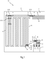
- Fig.1 1 shows a top view of a heating device 1 of a household appliance H.
- the heating device 1 can be used, for example, to heat water in a water tank of a steam generator.
- the household appliance H can also be an oven with steam cooking functionality, a dedicated steam cooker, an electrically heatable cooking space divider, a laundry care appliance, a dishwasher, a small household appliance, etc.
- the heating device 1 has a flat support 2 (e.g. made of sheet metal) with an electrically insulating support surface 3 (e.g. made of a slightly porous, for example thermally sprayed ceramic layer).
- a plurality of metallic layer structures 4 to 8 are thermally sprayed onto the carrier surface 3 .
- the thermally sprayed layer structures 4 to 8 are electrically insulated from one another by the carrier surface 3 and comprise: a first (long) meandering heating conductor track 4, a second (short) meandering heating conductor track 5 and three short straight conductor tracks 6 to 8.
- the two heating conductor tracks 4 and 5 are electrically connected to one another by two traces 9 made of a first solder or solder material 10 . As a result, the two heating conductors 4 and 5 electrically connected in series. If the second heating conductor track 5 is not to be used, instead of the two tracks 9, the two corresponding ends of the first heating conductor track 4 could be connected to one another directly by means of a track made of the first soldering material 10 (not illustrated).
- the electrical resistance can also be precisely trimmed in that a position of the lower track 9 between the heating conductor tracks 4 and 5 can be varied, as indicated by the double arrow.
- the common heating conductor track 4, 5 can consequently be trimmed by suitably attaching the tracks 9.
- the trace 9 of the first soldering material 10 has been ultrasonically soldered in one step from the surface of the first heating conductor 4 via the carrier surface 3 to the surface of the second heating conductor 5 . Due to the introduced ultrasonic energy, the first soldering material 10 holds both on the heating conductor tracks 4 and 5 and on the carrier surface 3 without the need for soldering flux.
- the trace 9 can be applied, for example, by soldering with an ultrasonic soldering iron.
- the three linear thermally sprayed conductor tracks 6 to 8 are connected to a connector plug 11 of the heating device 1, in particular to a respective electrical contact 11a of the connector plug 11.
- Adjacent conductor tracks 6 and 7 or 7 and 8 are connected via respective SMD components 12.
- the SMD components 12 are NTC resistors here, for example, which have electrical contacts or contact pads 14 in the form of soldering connections on their end regions.
- measured values eg electrical resistance values, voltage values or current values belonging to a respective temperature can be tapped via the plug trough 11 .
- the SMD components 12 are attached to the conductor tracks 6 and 7 or 7 and 8 via solder points 13 made of the first solder material 10 and a second solder material 15, as in FIG Fig.3 shown as section BB from heater 1.
- solder points 13 made of the first solder material 10
- a second solder material 15 as in FIG Fig.3 shown as section BB from heater 1.
- the conductor tracks 6 and 7 or 7 and 8 have been ultrasonically soldered with a volume of solder made of the first soldering material 10 .
- the SMD components 12 have been placed with their contact pads 14 on the respective solder volumes of the soldering material 10 .
- soldering volumes of the soldering material 10 are connected to the associated contact pads 14 by means of a non-ultrasonic soldering process (eg, laser soldering, reflow soldering, hand soldering, etc.) using the second solder material 15 has been soldered.
- a non-ultrasonic soldering process eg, laser soldering, reflow soldering, hand soldering, etc.
- the first solder material 10 and the second solder material 15 can be the same or different.
- the two conductor tracks 7 and 8 are electrically connected to one another by the SMD component 12 via the soldering points 13, which have (partial) solder volumes 13a and 13b made of the first soldering material 10 and the second soldering material 15, respectively.
- the electrical contacts 11a e.g. contact pins or contact pins
- the electrical contacts 11a of the connector plug 11 can also be attached to the conductor tracks 6 to 8, whereby they can have been immersed in a solder bath (not shown) before the connector plug 11 was installed.
- the solder bath can work with or without the introduction of ultrasound.
- the solder material applied in the solder bath can be, for example, one of the solder materials 10 or 15.
- Fig.4 shows a section CC from the heating device 1 as a sectional view in a side view.
- solder volume (solder point) 17 made of the first solder material 10 has been ultrasonically soldered and then a track 18 made of the second solder material 15 has been drawn from the solder volume 17 to the metallic contact surface 16, or vice versa, using a different soldering method (not based on ultrasound).
- the two thermally sprayed heating conductor tracks 4 and 5 could also each be provided with ultrasonically soldered solder volumes 17 made from the first solder material 10 , which are connected to one another via a track 18 made from the second solder material 15 .
- a conductive layer 19 has only been ultrasonically soldered onto the heating conductor 4 and possibly the carrier surface 3 in order to reduce a current density there and thus prevent the formation of so-called "hot spots", as in section DD in Fig.5 shown.
- a numerical specification can also include exactly the specified number as well as a usual tolerance range, as long as this is not explicitly excluded.
Landscapes
- Resistance Heating (AREA)
- Electric Connection Of Electric Components To Printed Circuits (AREA)
Description
- Die Erfindung betrifft ein Haushaltsgerät mit einer Heizvorrichtung. Erfindung betrifft ferner ein Verfahren zum Herstellen einer Heizeinrichtung für ein Haushaltsgerät.
- Die Erfindung ist insbesondere vorteilhaft anwendbar auf Gargeräte, insbesondere mit Dampfgarfunktionalität, auf Waschmaschinen, auf Spülmaschinen, auf Wäschepflegegeräte und auf Haushaltskleingeräte.
- Beim klassischen Löten (z.B. Laserlöten, Reflowlöten, Kolbenlöten usw.) von thermisch gespritzten Schichten wird die Verbindungs- oder Lötstelle mit Flussmittel behandelt, um ein Haften von Lot bzw. Lotmasse (auch als Lötmasse bezeichnet) zu ermöglichen. Denn typischerweise weist die thermisch gespritzte Schicht eine dünne Oxidschicht oder "Oxidhaut" auf, welche eine Haftung der Lotmasse stark erschwert oder sogar praktisch unmöglich macht. Das Flussmittel dient dazu, die Oxidhaut chemisch aufbrechen. Das Flussmittel dringt jedoch nachteiligerweise in die thermisch gespritzte Schicht ein, da diese typischerweise leicht porös ist. Es kann sogar weiter bis in darunterliegende poröse Schichten (beispielsweise eine Isolationsschicht) eindringen und deren Funktion beeinträchtigen. Um einen negativen Einfluss des Flussmittels (z.B. einen Verschlechterung einer elektrischen Isolationseigenschaft) zu vermeiden, muss es bisher aufwendig mit Lösemittel ausgewaschen werden.
- Es ist bisher bekannt, Leitflächen oder Anschlussflächen auf thermisch gespritzte Heizleiterschichten mittels thermisch gespritzter Metalle (z.B. Kupfer, Zinn, Bronze) herzustellen und diese Metalle dann mittels klassischer Lötverfahren zu verlöten. Für das Aufbringen nicht vollflächiger Anschlussflächen aus thermisch gespritzten Metallen (z.B. Anschlussflächen, Pads, usw.) muss aber aufwendig maskiert werden. Ein Verschleiß an Masken ist dabei hoch. Ein Auftragswirkungsgrad fällt dabei gering aus.
-
DE 10 2012 204 235 A1 offenbart ein Haushaltsgerät zum Zubereiten von Lebensmitteln, mit einem ersten Bauteil und einem mit dem ersten Bauteil verbundenen zweiten Bauteil, wobei zumindest an einer Verbindungsstelle der beiden Bauteile das erste Bauteil aus einem ersten Material und das zweite Bauteil aus einem zum ersten Material unterschiedlichen zweiten Material ausgebildet ist, und an der Verbindungsstelle zum Verbinden der Bauteile eine Lötverbindung ausgebildet ist, wobei die Lötverbindung eine Ultraschalllötverbindung ist.DE 10 2012 204 235 A1 betrifft auch ein Verfahren zum Herstellen eines Haushaltsgeräts. -
EP 0 963 143 A1 offenbart einen keramischen Träger mit einer elektrischen Schaltung und mit einer Anschlussvorrichtung, die wenigstens einen metallischen Anschluss, beispielsweise in Form eines Gewindebolzens, aufweist. Der Anschluss bzw. die Anschlussvorrichtung sind mit Ausgleichsmitteln, welche aus einem Metall mit einer höheren Verformbarkeit als das Material des Anschlusses bestehen, mit dem Träger verbunden, vorzugsweise mittels Aktivlötens. Die Ausgleichsmittel können in Form einer Ringscheibe o.dgl. ausgeführt sein und aus Kupfer bestehen und gleichen die Spannungen beim Abkühlen aus. Das Aktivlot weist vorteilhaft eine Basis aus Silber und Kupfer sowie eine reaktive Legierungskomponente, z.B. Titan oder ein Selten-Erd-Metall, auf. Die Anschlussvorrichtung kann sowohl einen hochbelastbaren mechanischen Befestigungsanschluss für den Träger als auch einen elektrischen Anschluss für die Schaltung darstellen. -
DE 20 2010 007 081 U1 offenbart eine Vorrichtung zum Erzeugen einer gasdichten Ultraschall-Lötverbindung zweier unterschiedlicher Materialien als Fügepartner A und B bei niedrigen Temperaturen, wobei diese eine entsprechende Bindungsfähigkeit mit dem verwendeten Lotmaterial aufweisen, mit den folgenden Merkmalen: einer Positionier- und Vorwärmeinrichtung für einen auf der Fügevorrichtung zuunterst liegenden Fügepartner B, einer Positionier- und Auflegeeinrichtung für den aufzusetzenden Fügepartner A, einer Aufwärm- und Löteinrichtung zum gemeinsamen Aufwärmen und Verlöten der Fügepartner A und B einer Entnahmeeinrichtung für die zusammengefügten Fügepartner A und B. -
DE 10 2013 201 386 A1 offenbart ein Kochfeld mit einer Kochfeldplatte, auf welcher zumindest eine Kochstelle ausgebildet ist, und einer Bedienvorrichtung, die Elektronikkomponenten umfasst, die in einer Draufsicht auf die Kochfeldplatte neben der Kochstelle positioniert sind, und einer Topferkennungseinrichtung, mit welcher die Position eines Zubereitungsgefäßes auf der Kochfeldplatte erkennbar ist, wobei die Topferkennungseinrichtung zumindest einen elektrisch leitenden Sensor aufweist, der als Leiterbahn an der Kochfeldplatte und zur positionellen Topferkennung zur elektrischen Wechselwirkung mit einem Zubereitungsgefäß ausgebildet ist, und zumindest abschnittweise als Flächenbegrenzung für eine Fläche auf der Kochfeldplatte angeordnet ist, innerhalb welcher die Elektronikkomponenten angeordnet sind. -
DE 10 2012 212 798 offenbart ein Haushaltsgerät mit einer Heizvorrichtung gemäß dem Oberbegriff des Anspruchs 1. - Es ist die Aufgabe der vorliegenden Erfindung, die Nachteile des Standes der Technik zumindest teilweise zu überwinden und insbesondere eine verbesserte Möglichkeit zur elektrischen Verbindung von thermisch aufgespritzten Schichten oder Schichtstrukturen eines Haushaltsgeräts bereitzustellen.
- Diese Aufgabe wird gemäß den Merkmalen der unabhängigen Ansprüche gelöst. Bevorzugte Ausführungsformen sind insbesondere den abhängigen Ansprüchen entnehmbar.
- Die Aufgabe wird gelöst durch ein Haushaltsgerät mit einer Heizvorrichtung, wobei die Heizvorrichtung einen flächigen Träger mit einer elektrisch isolierenden Trägeroberfläche, mindestens zwei auf die Trägeroberfläche thermisch aufgespritzte Schichtstrukturen und mindestens ein Lotvolumen, das auf mindestens einer thermisch aufgespritzten Schichtstruktur aufgebracht ist, aufweist, wobei das mindestens eine Lotvolumen ein ultraschall-aufgelötetes Lotvolumen ist, das die thermisch aufgespritzte Schichtstruktur mit mindestens einer weiteren thermisch aufgespritzten Schichtstruktur elektrisch verbindet.
- Diese Heizeinrichtung weist den Vorteil auf, dass das Lot bzw. die Lotmasse des Lotvolumens ohne weitere Hilfsstoffe fest an einer thermisch aufgespritzten Schichtstruktur haftet, und zwar mit einem geringen elektrischen Übergangswiderstand. Dies liegt daran, dass durch eine Einbringung von Ultraschallenergie die Oxidhaut der thermisch aufgespritzten Schichtstruktur aufgebrochen wird. Dadurch wird die Verbindung des Lots mit dem darunterliegenden nicht-oxidierten Material der thermisch gespritzten Schicht ermöglicht, und zwar insbesondere auch ohne Einsatz von Werkstoff ohne organische Anteile, insbesondere ohne Flussmittel.
- Das Lot bzw. die Lotmasse weist vorteilhafterweise eine hohe elektrische Leitfähigkeit auf. Insbesondere sind ein elektrischer Widerstand und eine Stromtragfähigkeit einer durch das Lot gebildeten elektrischen Leitung oder Lötverbindung so bemessen, dass eine Eignung über eine Schutzkleinspannung hinausgeht, und zwar insbesondere in einen Leistungsbereich (z.B. von 230 V bis mehr als 8 A). Besonders vorteilhafterweise ist die Lötverbindung auch für einen Einsatz im Hochspannungsbereich (z.B. ab ca. 1250 V AC oder 1800 V AC) ausreichend dimensioniert.
- Durch die Ultraschallunterstützung ist allgemein ein Auflöten von Lotmasse auf nicht mit klassischen Lötverfahren mit Lot benetzbaren Oberflächen möglich. Es ist allgemein möglich, auch sehr stark oxidierte Oberflächen oder nichtmetallische (z.B. glasartige oder keramische Oberflächen) fest und präzise mit Lot zu benetzen. So kann durch das Ultraschalllöten beispielsweise eine freiliegende keramische Isolierung (z.B. eine keramische Isolierschicht) auf einfache Weise mechanisch und elektrisch mit Lotmasse kontaktiert werden.
- Außerdem ist das Ultraschalllöten einfach anwendbar, da nicht maskiert zu werden braucht. Ferner ist es im Vergleich zum thermischen Spritzen von metallischen Anschlussschichten usw. deutlich effizienter in der Materialausnutzung (Materialeinsatz zur Erzeugung der Löt- oder Fügestelle). Zusätzlich kann eine Einsparung von Taktzeit und Kosten erreicht werden.
- Die gute Haftfestigkeit wird auch erreicht, wenn die thermisch aufgespritzte Schichtstruktur porös ist. Die gute Haftfestigkeit bleibt auch unter einer Temperaturwechselbeanspruchung bestehen.
- Außerdem ergibt sich der Vorteil, dass keine Korrosion in der Verbindungsstelle wie beim "klassischen" Löten mehr auftritt.
- Ferner ist die Ultraschall-Lötverbindung temperaturstabil bis mindestens 150°C ausgestaltbar. Sie kann zudem einen dem Substrat und/oder der thermisch aufgespritzten Schicht angepassten thermischen Ausdehnungskoeffizient aufweisen. Sie ist auch bei hohen Dauergebrauchstemperaturen über die gesamte Produktlebensdauer alterungsstabil.
- Unter einem flächigen Träger kann beispielsweise ein ebener Träger oder ein gekrümmter Träger (z.B. in Rohrform) verstanden werden. Der Träger kann insbesondere eine plattenartige Grundform aufweisen.
- Die elektrisch isolierende Trägeroberfläche kann eine auf einen Grundkörper oder Substrat des Trägers (z.B. ein Metallblech) aufgebrachte elektrisch isolierende Schicht (z.B. aus Keramik) sein. Diese Schicht kann ebenfalls thermisch aufgespritzt worden sein. Die elektrisch isolierende Trägeroberfläche kann aber auch ein oberflächenbehandelter (z.B. oxidierter) Schichtbereich eines Grundkörpers des Trägers sein. Die elektrisch isolierende Trägeroberfläche kann insbesondere eine nicht vernachlässigbare Porosität aufweisen. Bei Verwendung von Lotflussmittel kann dieses ggf. in die zugehörigen Poren eindringen und ggf. eine Fähigkeit zur elektrischen Isolierung - speziell bei angelegter Hochspannung - herabsetzen oder sogar praktisch aufheben. Insbesondere falls der Grundkörper bereits selbst elektrisch isolierend und temperaturbeständig (bis mindestens 150°C) ist, kann auch auf eine speziell ausgebildete oberflächliche Schicht verzichtet werden, und die Trägeroberfläche stellt dann die nicht-modifizierte Oberfläche des Grundkörpers dar. Dies kann beispielsweise der Fall sein, wenn der Grundkörper aus Keramik besteht.
- Die Trägeroberfläche kann zumindest an einer Flachseite, an der sich eine thermisch aufgespritzte Schicht oder Schichtstruktur befindet, vollflächig elektrisch isolierend ausgebildet sein. Alternativ ist die Trägeroberfläche nur unterhalb elektrisch leitfähiger Schichten oder Schichtstrukturen elektrisch isolierend ausgebildet, ggf. seitlich über die Schichten oder Schichtstrukturen hinausragend. So können elektrisch leitfähige thermisch gespritzte Schichtstrukturen auf gleich breite oder etwas breitere Schichtstrukturen aus einer elektrisch isolierenden Schicht thermisch aufgespritzt werden.
- Unter einer thermisch aufgespritzten Schicht kann eine Schicht verstanden werden, die beispielsweise durch Schmelzbadspritzen, Lichtbogenspritzen, Plasmaspritzen (z.B. Atmosphäre, unter Schutzgas oder unter niedrigem Druck), Flammspritzen (z.B. Pulverflammspritzen, Drahtflammspritzen oder Kunststoffflammspritzen), Hochgeschwindigkeit-Flammspritzen, Detonationsspritzen, Kaltgasspritzen, Laserspritzen oder PTWA-Spritzen hergestellt worden ist, insbesondere auf die Trägeroberfläche ausgespritzt worden ist. Falls mehrere thermisch aufgespritzte Schichten oder Schichtstrukturen vorhanden sind, können zumindest zwei davon gleich ausgebildet sein, z.B. im Hinblick auf ihr Material, ihre Schichtdicke usw. Auch können mindestens zwei thermisch aufgespritzte Schichtstrukturen unterschiedlich ausgebildet sein, z.B. im Hinblick auf ihr Material, ihre Schichtdicke usw.
- Zumindest eine thermisch aufgespritzte Schicht oder Schichtstruktur kann beispielsweise eine metallische Schicht oder Schichtstruktur sein, z.B. aufweisend Aluminium (Al), Bronze, Kupfer (Cu), Silber (Ag), Zinn (Sn) usw., oder eine Legierung davon. Die thermisch aufgespritzte Schicht kann auch eine Nickel-Chrom-Legierung (NiCr) sein. Die thermisch aufgespritzte Schicht kann zudem eine keramische Schicht sein, beispielsweise eine elektrisch isolierende Schicht. Eine Oberfläche der thermisch aufgespritzten Schicht oder Schichtstruktur kann oxidiert sein.
- Unter einer Schichtstruktur wird insbesondere eine Schicht verstanden, welche in Draufsicht eine von der Form der Trägeroberfläche unterschiedliche Form aufweist, also keine die ganze Trägeroberfläche vollflächig bedeckende Schicht ist. Vielmehr weist die Schichtstruktur auf dem Träger bzw. auf der Trägeroberfläche in Draufsicht eine eigene Kontur ("Außenkontur") auf, die zumindest teilweise auf der Trägeroberfläche (und nicht nur an ihrem Rand) verläuft. Die Schichtstruktur kann insbesondere in Form mindestens einer länglichen Leitungsspur oder Bahn vorliegen. Die Leitungsbahn kann ganz oder abschnittsweise geradlinig und/oder ganz oder abschnittsweise gekrümmt sein. Beispielsweise kann die Leitungsbahn einen mäanderförmigen Verlauf aufweisen. Die Leitungsbahn kann aber z.B. auch in Form eines kurzen Streifens oder eines rechteckigen, runden, ovalen usw. Kontaktfelds vorliegen.
- Ein ultraschall-aufgelötetes Lotvolumen ist insbesondere ein Lotvolumen, das mittels eines Ultraschall-Lötverfahrens aufgebracht worden ist.
- Es ist eine Ausgestaltung, dass mindestens eine thermisch aufgespritzte Schichtstruktur eine Widerstands-Heizleiterschicht ist, insbesondere eine Dickschicht. Die Heizleiterschicht kann insbesondere eine längliche Heizleiterbahn sein. Die Heizleiterbahn kann z.B. mäanderförmig oder spiralförmig verlaufen. Lotmasse kann insbesondere im Bereich mindestens eines Endes der Heizleiterschicht - insbesondere Heizleiterbahn - aufgebracht werden, um diese elektrisch anzuschließen. Als Material der Heizleiterschicht können insbesondere Aluminium, eine Aluminiumverbindung oder eine Nickel-ChromVerbindung vorgesehen sein. Die Heizleiterschicht kann also insbesondere eine thermisch aufgespritzte Flächenheizung für Haushaltsgeräte darstellen.
- Es ist außerdem eine Ausgestaltung, dass mindestens ein ultraschall-aufgelötetes Lotvolumen die thermisch aufgespritzte Schichtstruktur mit mindestens einer anderen Komponente der Heizeinrichtung elektrisch verbindet. Dadurch können besonders schnell, preiswert und sicher elektrische Verbindungen mit der thermisch aufgespritzten Schichtstruktur erzeugt werden.
- Es ist eine Weiterbildung, dass mindestens ein ultraschall-aufgelötetes Lotvolumen ein in einem Schritt bzw. einstufig hergestelltes Lotvolumen ist, was eine besonders einfache und schnelle elektrische Verbindung ermöglicht. Das Lotvolumen kann beispielsweise in einem Vorgang mittels eines Ultraschall-Lötkolbens zwischen der thermisch aufgespritzten Schichtstruktur und einer anderen Komponente aufgebracht werden.
- Es ist noch eine Ausgestaltung, dass mindestens ein ultraschall-aufgelötetes Lotvolumen mittels eines weiteren, nicht durch Ultraschall aufgebrachten Lotvolumens mit mindestens einer anderen Komponente der Heizeinrichtung elektrisch verbunden ist. Dies ergibt den Vorteil, dass ein Teil einer Lötverbindung auch mittels eines anderen Lötverfahrens (z.B. Laserlöten, Reflowlöten, Handlöten usw.) hergestellt sein kann, was eine besonders vielfältige Möglichkeit zur Aufbringung des Lotvolumens ermöglicht. So kann ein anderes Lötverfahren für bestimmte Oberflächen schonender und/oder für komplexe Geometrien einfach und schneller eine Verlötung herbeiführen. Bei dieser Ausgestaltung kann in einer Weiterbildung zunächst ein Lotvolumen auf eine thermisch aufgespritzte Schicht ultraschall-aufgelötet werden und dann das ultraschall-aufgelötete Lotvolumen über ein mit anderen Mitteln aufgebrachtes Lötvolumen elektrisch weiterverbunden werden. Das ultraschall-aufgelötete Lotvolumen dient somit als Basis oder Grund für das nicht durch Ultraschall aufgebrachte Lotvolumen. Das Aufbringen von Lotvolumina durch unterschiedliche Lötverfahren ist insbesondere im Rahmen eines mehrstufigen, z.B. zweistufigen, Verfahrens durchführbar.
- Es ist eine weitere Ausgestaltung, dass mindestens eine andere Komponente der Heizeinrichtung eine weitere thermisch aufgespritzte Schichtstruktur ist, an der mindestens ein ultraschall-aufgelötetes Lotvolumen vorhanden ist. Dann können z.B. in einer ersten Stufe beide thermisch aufgespritzten Schichtstrukturen (allg.: Fügepartner) mit einem ultraschall-aufgelöteten Lotvolumen versehen werden und folgend in einer zweiten Stufe die beiden ultraschall-aufgelöteten Lotvolumina mittels eines anderen Lötverfahrens miteinander verbunden werden.
- Beispielsweise kann so eine mit Lichtbogenspritzen hergestellte Schichtstruktur mit einer durch atmosphärisches Plasmaspritzen hergestellten Schichtstruktur verbunden werden, die durch einen Laserschnitt voneinander getrennt sind.
- Auch können so beispielsweise parallel verlaufende thermisch aufgespritzte Leiterbahnen über Lücken (z.B. Laserschnitte) hinweg miteinander verbunden werden. Dies kann z.B. zum nachträglichen Abgleich eines elektrischen Widerstands eines thermisch aufgespritzten Heizleiters genutzt werden, um eine geforderte Nennleistung der Heizeinrichtung zu gewährleisten ("Trimmen") und/oder um Fehlstellen in thermisch aufgespritzten Leiterbahnen (z.B. Heizleiterbahnen) zu reparieren.
- Es ist eine alternative Weiterbildung, dass das Lotvolumen in der zweiten Stufe ebenfalls ultraschall-aufgelötet wird oder worden ist. Dies entspricht einem zweistufigen Ultraschallverlöten mindestens einer thermisch aufgespritzten Schichtstruktur.
- Es ist noch eine weitere Ausgestaltung, dass mindestens eine andere Komponente der Heizeinrichtung ein metallischer Kontakt ist. Dann kann z.B. in einer ersten Stufe die thermisch aufgespritzte Schichtstruktur mit einem ultraschall-aufgelöteten Lotvolumen versehen werden und folgend in einer zweiten Stufe das ultraschall-aufgelötete Lotvolumen mittels eines anderen Lötverfahrens direkt mit dem metallischen Kontakt verbunden werden.
- Der metallische Kontakt kann z.B. ein durch Galvanisieren, Aufbringen einer metallischen Folie usw. auf die Trägeroberfläche aufgebrachtes Kontaktfeld sein, z.B. ein Kontaktelement, beispielweise aus Kupfer.
- Es ist ferner eine weitere Ausgestaltung, dass der metallische Kontakt ein Kontaktelement eines elektrischen oder elektronischen Bauelements ist, beispielsweise ein Kontaktstift eines Steckverbindungsteils (z.B. Anschlusssteckers) oder ein elektrischer Anschluss eines elektrischen oder elektronischen Bauteils (z.B. ein Kontaktbereich eines SMD-Bauteils wie eines NTC-Widerstands, einer Schmelzsicherung, eines - z.B. in Glaslot vergossenen - Sensors usw.). Dadurch kann eine thermisch gespritzte Schicht besonders einfach und langlebig mit einer Schaltung usw. verbunden werden. Das elektrische oder elektronische Bauelement ist vorteilhafterweise ein SMD ("Surface Mounted Device")-Bauteil. So können thermisch aufgespritzte Schichtstrukturen und elektrische und/oder elektronische Bauelemente besonders einfach und preiswert miteinander verbunden werden. Das SMD-Bauteil (z.B. der Größe 0603, 0805 oder 1206) kann mittels eines Vakuumgreifers platziert werden. Bedrahtete Bauteile, die für eine Durchsteckmontage ("THT-Through Hole Technology") vorgesehen sind, können ebenfalls über ihren metallischen Kontakt mit der thermisch aufgespritzten Struktur verbunden werden.
- Es ist auch eine Ausgestaltung, dass mindestens ein ultraschall-aufgelötetes Lotvolumen zumindest einen Abschnitt der thermisch aufgespritzten Schichtstruktur - insbesondere einer Heizleiterschicht - bedeckt, ohne sie mit einer anderen - insbesondere elektrisch leitfähigen - Komponente der Heizeinrichtung elektrisch zu verbinden. Es kann in dieser Ausgestaltung insbesondere mindestens eine Lotschicht (auch als "Leitschicht" bezeichnet) auf der Heizleiterschicht aufgebracht werden, um lokal eine elektrische Leistungsdichte in der Heizleiterschicht herabzusetzen. Dadurch wiederum kann lokal eine Erwärmung (sog. "Hot Spots") verhindert werden. Eine Leitschicht kann beispielsweise an Leistungsanschlüssen, an konstruktiv bedingten Verengungen in Leiterbahnen, an Ecken und/oder an Umkehrpunkten im Heizleiterlayout aufgebracht werden. Die Leitschicht bzw. das Lotmaterial kann dabei auch auf der Trägeroberfläche aufliegen.
- Das Haushaltsgerät kann beispielsweise ein Gargerät oder ein Zubehör für ein Gargerät (z.B. ein beheizbarer Garraumteiler) sein. Das Gargerät kann beispielsweise eine Dampfgarfunktion aufweisen, wobei die Heizeinrichtung einer Dampferzeugungsvorrichtung zugeordnet ist, um in der Dampferzeugungsvorrichtung vorhandenes Wasser zu verdampfen. Das Gargerät kann z.B. ein Backofen mit Dampfgarfunktionalität oder ein dedizierter Dampfgarer sein. Die Heizeinrichtung mag dann z.B. einen Boden eines Wassertanks darstellen.
- Für den Fall des beheizbaren Garraumteilers kann einseitig oder beidseitig mindestens eine thermisch aufgespritzte Schichtstruktur vorhanden sein, insbesondere mindestens eine Heizleiterschicht(struktur).
- Das Haushaltsgerät kann aber auch ein Wäschepflegegerät sein. Die Heizeinrichtung kann dann beispielsweise als Laugenheizung einer Waschmaschine oder eines Waschtrockners verwendet werden. Auch kann die Heizeinrichtung als Prozessluftheizung vorgesehen sein.
- Das Haushaltsgerät kann ferner eine Spülmaschine sein. Die Heizeinrichtung kann dann beispielsweise als Heizung zum Erwärmen der Spülflüssigkeit verwendet werden. In diesem Fall ist die Heizung insbesondere eine Komponente einer Heizpumpenbaugruppe.
- Das Haushaltsgerät kann zudem ein elektrisch betriebenes Haushaltskleingerät sein, z.B. ein Wasserkocher, eine Kaffeemaschine (z.B. in Form einer Espressomaschine), ein Toaster usw.
- Die Heizeinrichtung kann als ein Rohr (allgemein: ein rotationssymmetrischer Körper) ausgebildet sein, wobei mindestens ein thermisch aufgespritzter Dickschicht-Heizleiter an einer Wand des Rohrs des Haushaltsgeräts vorhanden ist. Das Rohr kann dann insbesondere als Durchlauferhitzer für dort durchgeleitetes Gas (z.B. Prozessluft) und/oder Flüssigkeit (z.B. zu verdampfendes Wasser, Spülflüssigkeit oder Lauge) verwendet oder angesehen werden.
- Die Aufgabe wird auch gelöst durch ein Verfahren zum Herstellen einer Heizeinrichtung für ein Haushaltsgerät, bei dem ein flächiger (ebener und/oder gekrümmter) Träger mit mindestens einer darauf aufgebrachten thermisch aufgespritzten Schichtstruktur bereitgestellt wird und auf mindestens eine thermisch aufgespritzten Schichtstruktur mindestens ein Lotvolumen ultraschall-aufgelötet wird. Das Verfahren ergibt die gleichen Vorteile wie die Heizeinrichtung und das Haushaltsgerät und kann analog dazu ausgebildet werden, und umgekehrt.
- So ist es eine Ausgestaltung, dass mindestens eine thermisch aufgespritzte Schichtstruktur einstufig mit einer anderen Komponente der Heizeinrichtung ultraschallverlötet wird. Dazu kann - z.B. mittels eines Ultraschalllötkolbens - in einem Vorgang eine Spur aus Lot von der mindestens einen thermisch aufgespritzten Schichtstruktur zu der anderen Komponente gezogen werden.
- Auch ist es eine Ausgestaltung, dass mindestens eine thermisch aufgespritzte Schichtstruktur zweistufig mit einer anderen Komponente der Heizeinrichtung ultraschallverlötet wird, indem in einer ersten Stufe zumindest an mindestens einer thermisch aufgespritzten Schichtstruktur ein Lotvolumen durch Ultraschalllöten aufgebracht wird und dieses Lotvolumen in einer zweiten Stufe mit der anderen Komponente der Heizeinrichtung verlötet wird. Das Verlöten in der zweiten Stufe kann mit oder ohne Ultraschall durchgeführt werden.
- Ferner ist es eine Ausgestaltung, dass die andere Komponente der Heizeinrichtung eine thermisch aufgespritzte Schichtstruktur ist, auf der in der ersten Stufe ein Lotvolumen durch Ultraschalllöten aufgebracht wird und dieses ultraschall-aufgebrachte Lotvolumen in der zweiten Stufe mit einem anderen ultraschall-aufgebrachten Lotvolumen der Heizeinrichtung verlötet wird.
- Außerdem ist es eine Ausgestaltung, dass das Ultraschalllöten mittels eines Ultraschall-Lötkolbens durchgeführt wird. Der Ultraschall-Lötkolben kann beispielsweise eine Sonotrode aufweisen, die als Lötspitze ausgeführt ist.
- Auch ist es eine Ausgestaltung, dass das Ultraschalllöten mittels eines Ultraschall-Lotbads (oder Lötbads) durchgeführt wird. Dabei kann eine mit Lot zu benetzende Komponente vor oder nach Montage an dem Träger in ein Lotbad eingetaucht werden. Das Benetzen dieser Komponente braucht also nicht an dem Träger vorgenommen zu werden, was eine vereinfachte Herstellung ermöglicht. Die jeweiligen Einzelschritte können ggf. durch einen Wärmebehandlungsprozess (z.B. durch ein Vorwärmen) der Komponente verbessert werden.
- Die oben beschriebenen Eigenschaften, Merkmale und Vorteile dieser Erfindung sowie die Art und Weise, wie diese erreicht werden, werden klarer und deutlicher verständlich im Zusammenhang mit der folgenden schematischen Beschreibung eines Ausführungsbeispiels, das im Zusammenhang mit den Zeichnungen näher erläutert wird.
- Fig.1
- zeigt in Draufsicht eine Skizze einer Heizeinrichtung eines Haushaltsgeräts;
- Fig.2
- zeigt als Schnittdarstellung in Seitenansicht einen ersten Ausschnitt aus der Heizeinrichtung nach
Fig.1 ; - Fig.3
- zeigt als Schnittdarstellung in Seitenansicht einen zweiten Ausschnitt aus der Heizeinrichtung nach
Fig.1 ; - Fig.4
- zeigt als Schnittdarstellung in Seitenansicht einen dritten Ausschnitt aus der Heizeinrichtung nach
Fig.1 ; und - Fig.5
- zeigt als Schnittdarstellung in Seitenansicht einen vierten Ausschnitt aus der Heizeinrichtung nach
Fig.1 . -
Fig.1 zeigt in Draufsicht eine Heizeinrichtung 1 eines Haushaltsgeräts H. Die Heizeinrichtung 1 kann beispielsweise zum Heizen von in einem Wassertank eines Dampferzeugers befindlichem Wasser verwendet werden. Das Haushaltsgerät H kann aber auch ein Backofen mit Dampfgarfunktionalität, ein dedizierter Dampfgarer, ein elektrisch beheizbarer Garraumteiler, ein Wäschepflegegerät, eine Spülmaschine, ein Haushaltskleingerät usw. sein. - Die Heizeinrichtung 1 weist einen flächigen Träger 2 (z.B. aus einem Metallblech) mit einer elektrisch isolierenden Trägeroberfläche 3 (z.B. aus einer leicht porösen, beispielsweise thermisch aufgespritzten Keramikschicht) auf. Auf der Trägeroberfläche 3 sind mehrere metallische Schichtstrukturen 4 bis 8 thermisch aufgespritzt. Die thermisch aufgespritzten Schichtstrukturen 4 bis 8 sind durch die Trägeroberfläche 3 voneinander elektrisch isoliert und umfassen: eine erste (lange) mäanderförmige Heizleiterbahn 4, eine zweite (kurze) mäanderförmige Heizleiterbahn 5 und drei kurze geradlinige Leiterbahnen 6 bis 8.
- Die beiden Heizleiterbahnen 4 und 5 sind durch zwei Spuren 9 aus einem ersten Lot oder Lotmaterial 10 elektrisch miteinander verbunden. Dadurch sind die beiden Heizleiterbahnen 4 und 5 elektrisch in Reihe geschaltet. Soll die zweite Heizleiterbahn 5 nicht verwendet werden, könnten anstelle der zwei Spuren 9 die beiden entsprechenden Enden der ersten Heizleiterbahn 4 direkt mittels einer Spur aus dem ersten Lotmaterial 10 miteinander verbunden sein (o. Abb.). Auch lässt sich der elektrische Widerstand dadurch genau trimmen, dass eine Position der hier unteren Spur 9 zwischen den Heizleiterbahnen 4 und 5 variiert werden kann, wie durch den Doppelpfeil angedeutet. Durch eine geeignete Anbringung der Spuren 9 kann folglich die gemeinsame Heizleiterbahn 4, 5 getrimmt werden.
- Wie in
Fig.2 im Schnitt A-A gezeigt, ist die Spur 9 des ersten Lotmaterial 10 dazu einstufig von der Oberfläche der ersten Heizleiterbahn 4 über die Trägeroberfläche 3 zu der Oberfläche der zweiten Heizleiterbahn 5 ultraschall-aufgelötet worden. Dabei hält das erste Lotmaterial 10 aufgrund der eingebrachten Ultraschallenergie sowohl auf den Heizleiterbahnen 4 und 5 als auch auf der Trägeroberfläche 3, ohne dass dazu Lötflussmittel benötigt wird. Die Spur 9 kann beispielsweise durch ein Verlöten mit einem Ultraschall-Lötkolben aufgebracht werden. - Wieder zurückkehrend zu
Fig.1 sind die drei geradlinigen thermisch aufgespritzten Leiterbahnen 6 bis 8 mit einem Anschlussstecker 11 der Heizeinrichtung 1 verbunden, insbesondere mit einem jeweiligen elektrischen Kontakt 11a des Anschlusssteckers 11. Benachbarte Leiterbahnen 6 und 7 bzw. 7 und 8 sind über jeweilige SMD-Bauelemente 12 verbunden. Die SMD-Bauelemente 12 sind hier beispielhaft NTC-Widerstände, die an ihren Stirnbereichen elektrische Kontakte oder Kontaktfelder 14 in Form von Lötanschlüssen aufweisen. So können über die Steckerwanne 11 zu einer jeweiligen Temperatur gehörige Messwerte (z.B. elektrische Widerstandswerte, Spannungswerte oder Stromwerte) abgegriffen werden. - Die SMD-Bauelemente 12 sind über Lötpunkte 13 aus dem ersten Lotmaterial 10 und einem zweiten Lotmaterial 15 an den Leiterbahnen 6 und 7 bzw. 7 und 8 befestigt, wie in
Fig.3 als Schnitt B-B aus der Heizeinrichtung 1 gezeigt. Dabei sind zunächst die Leiterbahnen 6 und 7 bzw. 7 und 8 mit einem Lotvolumen aus dem ersten Lotmaterial 10 ultraschallverlötet worden. Folgend sind die SMD-Bauelemente 12 mit ihren Kontaktfeldern 14 auf jeweilige Lotvolumina des Lötmaterials 10 aufgesetzt worden. Dann sind die Lotvolumina des Lötmaterials 10 mit den zugehörigen Kontaktfeldern 14 mittels eines Nicht-Ultraschall-Lötverfahrens (z.B. eines Laserlötens, Reflowlötens, Handlötens usw.) unter Verwendung des zweiten Lotmaterials 15 verlötet worden. Das erste Lotmaterial 10 und das zweite Lotmaterial 15 können gleich oder verschieden sein. - Folglich werden die beiden Leiterbahnen 7 und 8 durch das SMD-Bauelement 12 über die Lötpunkte 13, die (Teil-)Lotvolumina 13a und 13b aus dem ersten Lotmaterial 10 bzw. dem zweiten Lotmaterial 15 aufweisen, elektrisch miteinander verbunden.
- Analog können z.B. auch die elektrischen Kontakte 11a (z.B. Kontaktstifte oder Kontaktpins) des Anschlusssteckers 11 an die Leiterbahnen 6 bis 8 angebracht werden, wobei sie vor der Montage des Anschlusssteckers 11 in ein Lotbad (o. Abb.) getaucht worden sein können. Das Lotbad kann mit oder ohne Ultraschalleinbringung arbeiten. Das in dem Lotbad aufgebrachte Lotmaterial kann z.B. eines der Lotmaterialien 10 oder 15 sein.
- Wieder zurückkehrend zu
Fig.1 sind zudem zwei metallische Kontaktflächen 16 auf der Trägeroberfläche aufgebracht, über welche die kombinierte Heizleiterbahn 4 und 5 endseitig elektrisch angeschlossen werden kann, z.B. an eine Spannungsversorgung.Fig.4 zeigt dazu als Schnittdarstellung in Seitenansicht einen Schnitt C-C aus der Heizeinrichtung 1. - Auf der thermisch aufgespritzten Heizleiterbahn 4 ist dazu ähnlich zu
Fig.3 ein Lotvolumen (Lotpunkt) 17 aus dem ersten Lotmaterial 10 ultraschallaufgelötet worden und dann eine Spur 18 aus dem zweiten Lotmaterial 15 mit einem anderen (nicht auf Ultraschall beruhenden) Lötverfahren von dem Lotvolumen 17 zu der metallischen Kontaktfläche 16, oder umgekehrt, gezogen worden. - Analog könnten die beiden thermisch gespritzten Heizleiterbahnen 4 und 5 auch jeweils mit ultraschallaufgelöteten Lotvolumina 17 aus dem ersten Lotmaterial 10 versehen sein, die über eine Spur 18 aus dem zweiten Lotmaterial 15 miteinander verbunden sind.
- Wieder zurückkehrend zu
Fig.1 ist ferner an einer Biegung der Heizleiterbahn 4 eine Leitschicht 19 nur auf die Heizleiterbahn 4 und ggf. die Trägeroberfläche 3 ultraschallaufgelötet worden, um dort eine Stromdichte zu verringern und so eine Bildung von sog. "Hot Spots" zu verhindern, wie in Schnitt D-D inFig.5 gezeigt. - Selbstverständlich ist die vorliegende Erfindung nicht auf das gezeigte Ausführungsbeispiel beschränkt.
- Allgemein kann unter "ein", "eine" usw. eine Einzahl oder eine Mehrzahl verstanden werden, insbesondere im Sinne von "mindestens ein" oder "ein oder mehrere" usw., solange dies nicht explizit ausgeschlossen ist, z.B. durch den Ausdruck "genau ein" usw.
- Auch kann eine Zahlenangabe genau die angegebene Zahl als auch einen üblichen Toleranzbereich umfassen, solange dies nicht explizit ausgeschlossen ist.
-
- 1
- Heizeinrichtung
- 2
- Träger
- 3
- Trägeroberfläche
- 4
- Erste Heizleiterbahn
- 5
- Zweite Heizleiterbahn
- 6
- Leiterbahn
- 7
- Leiterbahn
- 8
- Leiterbahn
- 9
- Spur
- 10
- Erstes Lotmaterial
- 11
- Anschlussstecker
- 11a
- Elektrischer Kontakt des Anschlusssteckers
- 12
- SMD-Bauelement
- 13
- Lötpunkt
- 14
- Kontaktfeld
- 15
- Zweites Lotmaterial
- 16
- Metallische Kontaktfläche
- 17
- Lotvolumen
- 18
- Spur aus dem zweiten Lotmaterial
- 19
- Leitschicht
- H
- Haushaltsgerät
Claims (14)
- Haushaltsgerät (H) mit einer Heizeinrichtung (1), wobei die Heizeinrichtung (1)- einen flächigen Träger (2) mit einer Trägeroberfläche (3)- mindestens zwei eine auf die Trägeroberfläche (3) thermisch aufgespritzte Schichtstrukturen (4-8) und- mindestens ein Lotvolumen (9, 13a, 13b, 17, 18, 19), das auf mindestens zwei thermisch aufgespritzten Schichtstruktur (4-8) aufgebracht ist, aufweist, dadurch gekennzeichnet, dass- die Trägeroberfläche (3) eine elektrisch isolierende Trägeroberfläche ist,- mindestens ein Lotvolumen ein ultraschall-aufgelötetes Lotvolumen (9, 13a, 17, 19) ist,- das die thermisch aufgespritzte Schichtstruktur (4-8) mit mindestens einer weiteren thermisch aufgespritzten Schichtstruktur (4, 5) elektrisch verbindet.
- Haushaltsgerät (H) nach Anspruch 1, dadurch gekennzeichnet, dass mindestens eine thermisch aufgespritzte Schichtstruktur (4, 5) eine Widerstands-Heizleiterschicht ist.
- Haushaltsgerät (H) nach Anspruch 2, dadurch gekennzeichnet, dass- die beiden durch das ultraschall-aufgelötete Lotvolumen (9, 13a, 17, 19) elektrisch verbundenen thermisch aufgespritzten Schichtstrukturen (4-8) längliche Heizleiterbahnen sind und- das ultraschall-aufgelötete Lotvolumen (9, 13a, 17, 19) die Heizleiterbahnen über eine Lücke zwischen ihnen hinweg miteinander verbindet.
- Haushaltsgerät (H) nach einem der vorhergehenden Ansprüche, dadurch gekennzeichnet, dass die Trägeroberfläche (3) porös ist
- Haushaltsgerät (H) nach einem der vorhergehenden Ansprüche, dadurch gekennzeichnet, dass mindestens ein ultraschall-aufgelötetes Lotvolumen (13a, 17, 19) mittels eines weiteren, nicht durch Ultraschall aufgebrachten Lotvolumens (13b, 18) mit mindestens einer anderen Komponente der Heizeinrichtung (1) elektrisch verbunden ist.
- Haushaltsgerät (H) nach einem der vorhergehenden Ansprüche, dadurch gekennzeichnet, dass das ultraschall-aufgelötete Lotvolumen (9) als eine Spur von einer Oberfläche der thermisch aufgespritzten Schichtstruktur (4) über die Trägeroberfläche (3) zu einer Oberfläche der weiteren thermisch aufgespritzten Schichtstruktur (5) verläuft.
- Haushaltsgerät (H) nach einem der Ansprüche 3 bis 6, dadurch gekennzeichnet, dass zusätzlich mindestens eine andere Komponente der Heizeinrichtung (1) ein metallischer Kontakt (11a, 14, 16) ist.
- Haushaltsgerät (H) nach Anspruch 7, dadurch gekennzeichnet, dass der metallische Kontakt ein Kontakt (11a, 14) eines elektrischen oder elektronischen Bauelements (11, 12) ist.
- Haushaltsgerät (H) nach einem der vorhergehenden Ansprüche, dadurch gekennzeichnet, dass zusätzlich mindestens ein ultraschall-aufgelötetes Lotvolumen (19) zumindest einen Abschnitt der thermisch aufgespritzten Schichtstruktur (4) bedeckt ohne sie mit einer anderen elektrisch leitfähigen Komponente der Heizeinrichtung (1) elektrisch zu verbinden.
- Haushaltsgerät (H) nach einem der vorhergehenden Ansprüche, dadurch gekennzeichnet, dass das Haushaltsgerät ein Gargerät ist.
- Verfahren zum Herstellen einer Heizeinrichtung (1) für ein Haushaltsgerät (H), bei dem- ein flächiger Träger (2) mit einer elektrisch isolierenden Trägeroberfläche (3) und mit mindestens zwei darauf aufgebrachten thermisch aufgespritzten Schichtstrukturen (4-8) in Form länglicher Heizleiterbahnen, die durch eine Lücke voneinander getrennt sind, bereitgestellt wird und- die beiden Schichtstrukturen (4-8) mittels mindestens eines Lotvolumen (9, 13a, 17, 19), das auf die beiden Schichtstrukturen (4-8) ultraschall-aufgelötet wird, elektrisch verbunden werden.
- Verfahren nach Anspruch 11, bei dem mindestens eine thermisch aufgespritzte Schichtstruktur (4, 5) einstufig mit einer anderen Komponente (5, 4) der Heizeinrichtung (1) ultraschallverlötet wird.
- Verfahren nach einem der Ansprüche 11 oder 12, bei dem mindestens eine thermisch aufgespritzte Schichtstruktur (4, 6-8) zweistufig mit einer anderen Komponente (5, 11a, 12) der Heizeinrichtung (1) ultraschallverlötet wird, indem in einer ersten Stufe zumindest an mindestens einer thermisch aufgespritzten Schichtstruktur (4, 6-8) ein Lotvolumen (13a, 17) durch Ultraschalllöten aufgebracht wird und dieses Lotvolumen (13a, 17) in einer zweiten Stufe mit der anderen Komponente (5, 11a, 12) der Heizeinrichtung (1) verlötet wird.
- Verfahren nach Anspruch 13, bei dem die andere Komponente der Heizeinrichtung (1) eine thermisch aufgespritzte Schichtstruktur ist, auf der in der ersten Stufe ein Lotvolumen durch Ultraschalllöten aufgebracht wird und dieses ultraschall-aufgebrachte Lotvolumen in der zweiten Stufe mit einem anderen ultraschall-aufgebrachten Lotvolumen der Heizeinrichtung (1) verlötet wird.
Applications Claiming Priority (2)
| Application Number | Priority Date | Filing Date | Title |
|---|---|---|---|
| DE102015214627.8A DE102015214627A1 (de) | 2015-07-31 | 2015-07-31 | Verbinden thermisch aufgespritzter Schichtstrukturen von Heizeinrichtungen |
| PCT/EP2016/065541 WO2017021076A1 (de) | 2015-07-31 | 2016-07-01 | Verbinden thermisch aufgespritzter schichtstrukturen von heizeinrichtungen |
Publications (2)
| Publication Number | Publication Date |
|---|---|
| EP3329737A1 EP3329737A1 (de) | 2018-06-06 |
| EP3329737B1 true EP3329737B1 (de) | 2022-04-13 |
Family
ID=56464176
Family Applications (1)
| Application Number | Title | Priority Date | Filing Date |
|---|---|---|---|
| EP16740977.0A Active EP3329737B1 (de) | 2015-07-31 | 2016-07-01 | Verbinden thermisch aufgespritzter schichtstrukturen von heizeinrichtungen |
Country Status (6)
| Country | Link |
|---|---|
| US (1) | US11641698B2 (de) |
| EP (1) | EP3329737B1 (de) |
| CN (1) | CN107926084B (de) |
| DE (1) | DE102015214627A1 (de) |
| PL (1) | PL3329737T3 (de) |
| WO (1) | WO2017021076A1 (de) |
Families Citing this family (2)
| Publication number | Priority date | Publication date | Assignee | Title |
|---|---|---|---|---|
| DE102019213241A1 (de) * | 2019-07-26 | 2021-01-28 | Siemens Aktiengesellschaft | Verfahren zum thermischen Sprühen von Leiterbahnen und Elektronikmodul |
| TWI748571B (zh) * | 2020-07-22 | 2021-12-01 | 敏翔股份有限公司 | 具加熱功能之裝置之電連接部 |
Family Cites Families (35)
| Publication number | Priority date | Publication date | Assignee | Title |
|---|---|---|---|---|
| US3440720A (en) * | 1966-12-01 | 1969-04-29 | Corning Glass Works | Method of making electric heating units |
| JPH01194282A (ja) * | 1988-01-28 | 1989-08-04 | Ngk Insulators Ltd | セラミック・ヒータ及び電気化学的素子並びに酸素分析装置 |
| DE4126533A1 (de) * | 1991-08-10 | 1993-02-11 | Ver Glaswerke Gmbh | Verfahren zum kontaktieren von elektrisch heizbaren glasscheiben mit transparenten heizwiderstandsschichten |
| US5355144A (en) * | 1992-03-16 | 1994-10-11 | The Ohio State University | Transparent window antenna |
| JPH07106729A (ja) * | 1993-09-30 | 1995-04-21 | Murata Mfg Co Ltd | 厚膜回路部品の製造方法 |
| US5670966A (en) * | 1994-12-27 | 1997-09-23 | Ppg Industries, Inc. | Glass antenna for vehicle window |
| GB9511618D0 (en) * | 1995-06-08 | 1995-08-02 | Deeman Product Dev Limited | Electrical heating elements |
| US6037572A (en) * | 1997-02-26 | 2000-03-14 | White Consolidated Industries, Inc. | Thin film heating assemblies |
| US6762396B2 (en) * | 1997-05-06 | 2004-07-13 | Thermoceramix, Llc | Deposited resistive coatings |
| DE19825451A1 (de) | 1998-06-06 | 1999-12-09 | Ego Elektro Geraetebau Gmbh | Keramischer Träger mit einer elektrischen Schaltung und mit einer Anschlußvorrichtung |
| EP1193233A1 (de) * | 2000-02-07 | 2002-04-03 | Ibiden Co., Ltd. | Keramisches substrat zur herstellung von halbleitern/inspektions vorrichtung |
| US6919543B2 (en) * | 2000-11-29 | 2005-07-19 | Thermoceramix, Llc | Resistive heaters and uses thereof |
| US6924468B2 (en) * | 2002-12-14 | 2005-08-02 | Thermoceramix, Inc. | System and method for heating materials |
| DE602004011386T2 (de) * | 2003-11-20 | 2009-01-08 | Koninklijke Philips Electronics N.V. | Dünnschichtheizelement |
| DE10355043A1 (de) * | 2003-11-25 | 2005-06-23 | Watlow Electric Manufacturing Co., St. Louis | Verfahren zum Befestigen eines elektrischen Leiters auf einem Flächenelement, sowie Heißkanalelement, insbesondere für eine Kunststoff-Spritzeinrichtung |
| US20060278631A1 (en) * | 2005-06-10 | 2006-12-14 | Challenge Carbon Technology Co., Ltd. Of Taiwan | Laminate fabric heater and method of making |
| US8428445B2 (en) * | 2007-02-20 | 2013-04-23 | Thermoceramix, Inc. | Gas heating apparatus and methods |
| EP2517533A1 (de) * | 2009-07-31 | 2012-10-31 | American Roller Company LLC | Verfahren und vorrichtung zur ausstattung einer maschinentrommel mit einem heizaggregat |
| EP2491758A1 (de) * | 2009-10-22 | 2012-08-29 | Datec Coating Corporation | Verfahren zur schmelzbindung eines thermoplastischen hochtemperatur-erwärmungselements an ein substrat |
| DE102009059995A1 (de) * | 2009-12-21 | 2011-06-22 | W.E.T. Automotive Systems AG, 85235 | Elektrische Heizeinrichtung |
| DE202010007081U1 (de) | 2010-05-21 | 2010-08-26 | Bayerisches Zentrum für Angewandte Energieforschung e.V. | Vorrichtung zum Erzeugen einer gasdichten Ultraschall-Lötverbindung |
| EP2393337B1 (de) * | 2010-06-07 | 2013-01-23 | SMR Patents S.à.r.l. | Heizeinrichtung |
| ES2643181T3 (es) * | 2011-12-20 | 2017-11-21 | Saint-Gobain Glass France | Cubierta de luminaria calefactable |
| DE102012212798A1 (de) * | 2011-12-22 | 2013-06-27 | Robert Bosch Gmbh | Heizelement und Verfahren zu dessen Herstellung sowie Verwendung des Heizelementes |
| WO2013107749A1 (de) * | 2012-01-20 | 2013-07-25 | Saint-Gobain Glass France | Anschlusselement |
| DE102012204235B4 (de) | 2012-03-16 | 2024-02-29 | BSH Hausgeräte GmbH | Haushaltsgerät zum Zubereiten von Lebensmitteln mit einer Ultraschall-Lötverbindung sowie Verfahren zum Herstellen eines derartigen Haushaltsgeräts |
| TWI558039B (zh) * | 2012-06-06 | 2016-11-11 | 法國聖戈本玻璃公司 | 帶有電連接元件之板、製造彼之方法、及彼之用途 |
| US10118364B2 (en) * | 2012-10-30 | 2018-11-06 | Saint-Gobain Glass France | Polymeric vehicle glazing with a flush mounted opaque edge zone |
| DE102013201386A1 (de) | 2013-01-29 | 2014-07-31 | BSH Bosch und Siemens Hausgeräte GmbH | Kochfeld mit einer Kochfeldplatte und einer Leiterbahn als Flächenbegrenzung für Elektronikkomponenten |
| US9623951B2 (en) * | 2013-08-21 | 2017-04-18 | Goodrich Corporation | Heating elements for aircraft heated floor panels |
| JPWO2015045343A1 (ja) * | 2013-09-26 | 2017-03-09 | パナソニックIpマネジメント株式会社 | 赤外線放射素子及びその製造方法 |
| WO2016055208A1 (de) * | 2014-10-07 | 2016-04-14 | Saint-Gobain Glass France | Verfahren zur herstellung einer scheibe mit elektrisch leitfähiger beschichtung und einem darauf angelöteten metallischen band; entsprechende scheibe |
| DE102014116275A1 (de) * | 2014-11-07 | 2016-05-12 | Webasto SE | Verfahren zur Herstellung eines Kontaktbereichs für eine Schicht eines elektrischen Heizgeräts sowie Vorrichtung für ein elektrisches Heizgerät für ein Kraftfahrzeug |
| DE102015214628A1 (de) * | 2015-07-31 | 2017-02-02 | BSH Hausgeräte GmbH | Heizeinrichtung für ein Haushaltsgerät |
| KR102466203B1 (ko) * | 2016-03-22 | 2022-11-11 | 삼성전기주식회사 | 커패시터 및 그 제조방법 |
-
2015
- 2015-07-31 DE DE102015214627.8A patent/DE102015214627A1/de not_active Withdrawn
-
2016
- 2016-07-01 EP EP16740977.0A patent/EP3329737B1/de active Active
- 2016-07-01 WO PCT/EP2016/065541 patent/WO2017021076A1/de not_active Ceased
- 2016-07-01 PL PL16740977.0T patent/PL3329737T3/pl unknown
- 2016-07-01 CN CN201680044726.2A patent/CN107926084B/zh active Active
- 2016-07-01 US US15/747,171 patent/US11641698B2/en active Active
Non-Patent Citations (1)
| Title |
|---|
| None * |
Also Published As
| Publication number | Publication date |
|---|---|
| PL3329737T3 (pl) | 2022-07-25 |
| CN107926084A (zh) | 2018-04-17 |
| DE102015214627A1 (de) | 2017-02-02 |
| CN107926084B (zh) | 2021-07-27 |
| US20180213607A1 (en) | 2018-07-26 |
| WO2017021076A1 (de) | 2017-02-09 |
| US11641698B2 (en) | 2023-05-02 |
| EP3329737A1 (de) | 2018-06-06 |
Similar Documents
| Publication | Publication Date | Title |
|---|---|---|
| DE69619521T2 (de) | Elektrische heizelemente | |
| DE69834791T2 (de) | Heizelement | |
| EP1152639B1 (de) | Elektrische Heizeinheit, insbesondere für flüssige Medien | |
| EP0229928A2 (de) | Heizelement für thermische Hausgeräte, insbesondere für Kochstellen | |
| DE3545454A1 (de) | Heizelement fuer thermische hausgeraete, insb. fuer kochstellen | |
| EP0993233B1 (de) | Induktor für ein Induktions-Kochfeld | |
| EP0254070B1 (de) | Elektro-Bauelement | |
| DE3409925A1 (de) | Heizkoerper fuer haushaltgeraete | |
| WO2016050588A1 (de) | Thermoelektrische vorrichtung | |
| EP0809094A1 (de) | Verfahren zur Herstellung einer Sensoranordung für die Temperaturmessung | |
| EP3329736B1 (de) | Heizeinrichtung für ein haushaltsgerät | |
| EP1927132B1 (de) | Verfahren zur herstellung eines leistungshalbleitermoduls | |
| DE10110789C1 (de) | Kochgerät mit einer nicht planaren, mehrdimensional geformten Kochfläche aus Glas- oder Glaskeramik | |
| EP3329737A1 (de) | Verbinden thermisch aufgespritzter schichtstrukturen von heizeinrichtungen | |
| DE663355C (de) | Vorrichtung zur Messung und Regelung temperaturabhaengiger Vorgaenge | |
| DE19961781C2 (de) | Laminierbare Heizungsfolie mit hoher Temperaturbeständigkeit und Verfahren zum Aufbringen einer derartigen Heizungsfolie auf ein Trägermaterial | |
| DE2748239A1 (de) | Verfahren zum kontaktieren eines elektrischen kaltleiter-widerstandes mit einem anschlusselement | |
| DE102005056501A1 (de) | Flaches Induktionskochsystem | |
| DE102024119573B3 (de) | Verfahren zum Bilden einer Schaltkreisvorrichtung und Schaltkreisvorrichtung | |
| EP1519630B1 (de) | Heizvorrichtung für ein Gargerät oder dergleichen | |
| DE29617732U1 (de) | Kochmulde | |
| DE102021126808A1 (de) | Verfahren zur Herstellung eines Kochgeschirrs und Kochgeschirr | |
| DE102010062508A1 (de) | Heizung für ein Hausgerät sowie Haushaltsgerät | |
| WO2016046666A1 (de) | Hausgerätevorrichtung und verfahren zur herstellung einer hausgerätevorrichtung | |
| EP3893601A1 (de) | Küchengeschirr und verfahren zur herstellung eines küchengeschirrs und küchengeschirrerzeugnis |
Legal Events
| Date | Code | Title | Description |
|---|---|---|---|
| STAA | Information on the status of an ep patent application or granted ep patent |
Free format text: STATUS: THE INTERNATIONAL PUBLICATION HAS BEEN MADE |
|
| PUAI | Public reference made under article 153(3) epc to a published international application that has entered the european phase |
Free format text: ORIGINAL CODE: 0009012 |
|
| STAA | Information on the status of an ep patent application or granted ep patent |
Free format text: STATUS: REQUEST FOR EXAMINATION WAS MADE |
|
| 17P | Request for examination filed |
Effective date: 20180228 |
|
| AK | Designated contracting states |
Kind code of ref document: A1 Designated state(s): AL AT BE BG CH CY CZ DE DK EE ES FI FR GB GR HR HU IE IS IT LI LT LU LV MC MK MT NL NO PL PT RO RS SE SI SK SM TR |
|
| AX | Request for extension of the european patent |
Extension state: BA ME |
|
| RIN1 | Information on inventor provided before grant (corrected) |
Inventor name: KUEHN, ROBERT Inventor name: KOBLER, STEFAN Inventor name: SCHALLER, PHILIPP |
|
| DAV | Request for validation of the european patent (deleted) | ||
| DAX | Request for extension of the european patent (deleted) | ||
| STAA | Information on the status of an ep patent application or granted ep patent |
Free format text: STATUS: EXAMINATION IS IN PROGRESS |
|
| 17Q | First examination report despatched |
Effective date: 20200430 |
|
| GRAP | Despatch of communication of intention to grant a patent |
Free format text: ORIGINAL CODE: EPIDOSNIGR1 |
|
| STAA | Information on the status of an ep patent application or granted ep patent |
Free format text: STATUS: GRANT OF PATENT IS INTENDED |
|
| INTG | Intention to grant announced |
Effective date: 20211207 |
|
| GRAS | Grant fee paid |
Free format text: ORIGINAL CODE: EPIDOSNIGR3 |
|
| GRAA | (expected) grant |
Free format text: ORIGINAL CODE: 0009210 |
|
| STAA | Information on the status of an ep patent application or granted ep patent |
Free format text: STATUS: THE PATENT HAS BEEN GRANTED |
|
| AK | Designated contracting states |
Kind code of ref document: B1 Designated state(s): AL AT BE BG CH CY CZ DE DK EE ES FI FR GB GR HR HU IE IS IT LI LT LU LV MC MK MT NL NO PL PT RO RS SE SI SK SM TR |
|
| REG | Reference to a national code |
Ref country code: GB Ref legal event code: FG4D Free format text: NOT ENGLISH |
|
| REG | Reference to a national code |
Ref country code: CH Ref legal event code: EP |
|
| REG | Reference to a national code |
Ref country code: DE Ref legal event code: R096 Ref document number: 502016014767 Country of ref document: DE |
|
| REG | Reference to a national code |
Ref country code: IE Ref legal event code: FG4D Free format text: LANGUAGE OF EP DOCUMENT: GERMAN |
|
| REG | Reference to a national code |
Ref country code: AT Ref legal event code: REF Ref document number: 1484412 Country of ref document: AT Kind code of ref document: T Effective date: 20220515 |
|
| REG | Reference to a national code |
Ref country code: LT Ref legal event code: MG9D |
|
| REG | Reference to a national code |
Ref country code: NL Ref legal event code: MP Effective date: 20220413 |
|
| PG25 | Lapsed in a contracting state [announced via postgrant information from national office to epo] |
Ref country code: NL Free format text: LAPSE BECAUSE OF FAILURE TO SUBMIT A TRANSLATION OF THE DESCRIPTION OR TO PAY THE FEE WITHIN THE PRESCRIBED TIME-LIMIT Effective date: 20220413 |
|
| PG25 | Lapsed in a contracting state [announced via postgrant information from national office to epo] |
Ref country code: SE Free format text: LAPSE BECAUSE OF FAILURE TO SUBMIT A TRANSLATION OF THE DESCRIPTION OR TO PAY THE FEE WITHIN THE PRESCRIBED TIME-LIMIT Effective date: 20220413 Ref country code: PT Free format text: LAPSE BECAUSE OF FAILURE TO SUBMIT A TRANSLATION OF THE DESCRIPTION OR TO PAY THE FEE WITHIN THE PRESCRIBED TIME-LIMIT Effective date: 20220816 Ref country code: NO Free format text: LAPSE BECAUSE OF FAILURE TO SUBMIT A TRANSLATION OF THE DESCRIPTION OR TO PAY THE FEE WITHIN THE PRESCRIBED TIME-LIMIT Effective date: 20220713 Ref country code: LT Free format text: LAPSE BECAUSE OF FAILURE TO SUBMIT A TRANSLATION OF THE DESCRIPTION OR TO PAY THE FEE WITHIN THE PRESCRIBED TIME-LIMIT Effective date: 20220413 Ref country code: HR Free format text: LAPSE BECAUSE OF FAILURE TO SUBMIT A TRANSLATION OF THE DESCRIPTION OR TO PAY THE FEE WITHIN THE PRESCRIBED TIME-LIMIT Effective date: 20220413 Ref country code: GR Free format text: LAPSE BECAUSE OF FAILURE TO SUBMIT A TRANSLATION OF THE DESCRIPTION OR TO PAY THE FEE WITHIN THE PRESCRIBED TIME-LIMIT Effective date: 20220714 Ref country code: FI Free format text: LAPSE BECAUSE OF FAILURE TO SUBMIT A TRANSLATION OF THE DESCRIPTION OR TO PAY THE FEE WITHIN THE PRESCRIBED TIME-LIMIT Effective date: 20220413 Ref country code: ES Free format text: LAPSE BECAUSE OF FAILURE TO SUBMIT A TRANSLATION OF THE DESCRIPTION OR TO PAY THE FEE WITHIN THE PRESCRIBED TIME-LIMIT Effective date: 20220413 Ref country code: BG Free format text: LAPSE BECAUSE OF FAILURE TO SUBMIT A TRANSLATION OF THE DESCRIPTION OR TO PAY THE FEE WITHIN THE PRESCRIBED TIME-LIMIT Effective date: 20220713 |
|
| PG25 | Lapsed in a contracting state [announced via postgrant information from national office to epo] |
Ref country code: RS Free format text: LAPSE BECAUSE OF FAILURE TO SUBMIT A TRANSLATION OF THE DESCRIPTION OR TO PAY THE FEE WITHIN THE PRESCRIBED TIME-LIMIT Effective date: 20220413 Ref country code: LV Free format text: LAPSE BECAUSE OF FAILURE TO SUBMIT A TRANSLATION OF THE DESCRIPTION OR TO PAY THE FEE WITHIN THE PRESCRIBED TIME-LIMIT Effective date: 20220413 Ref country code: IS Free format text: LAPSE BECAUSE OF FAILURE TO SUBMIT A TRANSLATION OF THE DESCRIPTION OR TO PAY THE FEE WITHIN THE PRESCRIBED TIME-LIMIT Effective date: 20220813 |
|
| REG | Reference to a national code |
Ref country code: DE Ref legal event code: R097 Ref document number: 502016014767 Country of ref document: DE |
|
| PG25 | Lapsed in a contracting state [announced via postgrant information from national office to epo] |
Ref country code: SM Free format text: LAPSE BECAUSE OF FAILURE TO SUBMIT A TRANSLATION OF THE DESCRIPTION OR TO PAY THE FEE WITHIN THE PRESCRIBED TIME-LIMIT Effective date: 20220413 Ref country code: SK Free format text: LAPSE BECAUSE OF FAILURE TO SUBMIT A TRANSLATION OF THE DESCRIPTION OR TO PAY THE FEE WITHIN THE PRESCRIBED TIME-LIMIT Effective date: 20220413 Ref country code: RO Free format text: LAPSE BECAUSE OF FAILURE TO SUBMIT A TRANSLATION OF THE DESCRIPTION OR TO PAY THE FEE WITHIN THE PRESCRIBED TIME-LIMIT Effective date: 20220413 Ref country code: EE Free format text: LAPSE BECAUSE OF FAILURE TO SUBMIT A TRANSLATION OF THE DESCRIPTION OR TO PAY THE FEE WITHIN THE PRESCRIBED TIME-LIMIT Effective date: 20220413 Ref country code: DK Free format text: LAPSE BECAUSE OF FAILURE TO SUBMIT A TRANSLATION OF THE DESCRIPTION OR TO PAY THE FEE WITHIN THE PRESCRIBED TIME-LIMIT Effective date: 20220413 Ref country code: CZ Free format text: LAPSE BECAUSE OF FAILURE TO SUBMIT A TRANSLATION OF THE DESCRIPTION OR TO PAY THE FEE WITHIN THE PRESCRIBED TIME-LIMIT Effective date: 20220413 |
|
| PLBE | No opposition filed within time limit |
Free format text: ORIGINAL CODE: 0009261 |
|
| STAA | Information on the status of an ep patent application or granted ep patent |
Free format text: STATUS: NO OPPOSITION FILED WITHIN TIME LIMIT |
|
| PG25 | Lapsed in a contracting state [announced via postgrant information from national office to epo] |
Ref country code: MC Free format text: LAPSE BECAUSE OF FAILURE TO SUBMIT A TRANSLATION OF THE DESCRIPTION OR TO PAY THE FEE WITHIN THE PRESCRIBED TIME-LIMIT Effective date: 20220413 |
|
| REG | Reference to a national code |
Ref country code: CH Ref legal event code: PL |
|
| 26N | No opposition filed |
Effective date: 20230116 |
|
| REG | Reference to a national code |
Ref country code: BE Ref legal event code: MM Effective date: 20220731 |
|
| PG25 | Lapsed in a contracting state [announced via postgrant information from national office to epo] |
Ref country code: AL Free format text: LAPSE BECAUSE OF FAILURE TO SUBMIT A TRANSLATION OF THE DESCRIPTION OR TO PAY THE FEE WITHIN THE PRESCRIBED TIME-LIMIT Effective date: 20220413 |
|
| PG25 | Lapsed in a contracting state [announced via postgrant information from national office to epo] |
Ref country code: LU Free format text: LAPSE BECAUSE OF NON-PAYMENT OF DUE FEES Effective date: 20220701 Ref country code: LI Free format text: LAPSE BECAUSE OF NON-PAYMENT OF DUE FEES Effective date: 20220731 Ref country code: FR Free format text: LAPSE BECAUSE OF NON-PAYMENT OF DUE FEES Effective date: 20220731 Ref country code: CH Free format text: LAPSE BECAUSE OF NON-PAYMENT OF DUE FEES Effective date: 20220731 |
|
| PG25 | Lapsed in a contracting state [announced via postgrant information from national office to epo] |
Ref country code: SI Free format text: LAPSE BECAUSE OF FAILURE TO SUBMIT A TRANSLATION OF THE DESCRIPTION OR TO PAY THE FEE WITHIN THE PRESCRIBED TIME-LIMIT Effective date: 20220413 Ref country code: BE Free format text: LAPSE BECAUSE OF NON-PAYMENT OF DUE FEES Effective date: 20220731 |
|
| PG25 | Lapsed in a contracting state [announced via postgrant information from national office to epo] |
Ref country code: IE Free format text: LAPSE BECAUSE OF NON-PAYMENT OF DUE FEES Effective date: 20220701 |
|
| REG | Reference to a national code |
Ref country code: AT Ref legal event code: MM01 Ref document number: 1484412 Country of ref document: AT Kind code of ref document: T Effective date: 20220701 |
|
| PG25 | Lapsed in a contracting state [announced via postgrant information from national office to epo] |
Ref country code: AT Free format text: LAPSE BECAUSE OF NON-PAYMENT OF DUE FEES Effective date: 20220701 |
|
| PG25 | Lapsed in a contracting state [announced via postgrant information from national office to epo] |
Ref country code: IT Free format text: LAPSE BECAUSE OF FAILURE TO SUBMIT A TRANSLATION OF THE DESCRIPTION OR TO PAY THE FEE WITHIN THE PRESCRIBED TIME-LIMIT Effective date: 20220413 |
|
| PG25 | Lapsed in a contracting state [announced via postgrant information from national office to epo] |
Ref country code: HU Free format text: LAPSE BECAUSE OF FAILURE TO SUBMIT A TRANSLATION OF THE DESCRIPTION OR TO PAY THE FEE WITHIN THE PRESCRIBED TIME-LIMIT; INVALID AB INITIO Effective date: 20160701 |
|
| PG25 | Lapsed in a contracting state [announced via postgrant information from national office to epo] |
Ref country code: MK Free format text: LAPSE BECAUSE OF FAILURE TO SUBMIT A TRANSLATION OF THE DESCRIPTION OR TO PAY THE FEE WITHIN THE PRESCRIBED TIME-LIMIT Effective date: 20220413 Ref country code: CY Free format text: LAPSE BECAUSE OF FAILURE TO SUBMIT A TRANSLATION OF THE DESCRIPTION OR TO PAY THE FEE WITHIN THE PRESCRIBED TIME-LIMIT Effective date: 20220413 |
|
| PG25 | Lapsed in a contracting state [announced via postgrant information from national office to epo] |
Ref country code: MT Free format text: LAPSE BECAUSE OF FAILURE TO SUBMIT A TRANSLATION OF THE DESCRIPTION OR TO PAY THE FEE WITHIN THE PRESCRIBED TIME-LIMIT Effective date: 20220413 |
|
| PG25 | Lapsed in a contracting state [announced via postgrant information from national office to epo] |
Ref country code: BG Free format text: LAPSE BECAUSE OF FAILURE TO SUBMIT A TRANSLATION OF THE DESCRIPTION OR TO PAY THE FEE WITHIN THE PRESCRIBED TIME-LIMIT Effective date: 20220413 |
|
| PG25 | Lapsed in a contracting state [announced via postgrant information from national office to epo] |
Ref country code: BG Free format text: LAPSE BECAUSE OF FAILURE TO SUBMIT A TRANSLATION OF THE DESCRIPTION OR TO PAY THE FEE WITHIN THE PRESCRIBED TIME-LIMIT Effective date: 20220413 |
|
| PGFP | Annual fee paid to national office [announced via postgrant information from national office to epo] |
Ref country code: PL Payment date: 20250624 Year of fee payment: 10 |
|
| PGFP | Annual fee paid to national office [announced via postgrant information from national office to epo] |
Ref country code: TR Payment date: 20250626 Year of fee payment: 10 |
|
| PGFP | Annual fee paid to national office [announced via postgrant information from national office to epo] |
Ref country code: DE Payment date: 20250731 Year of fee payment: 10 |
|
| PGFP | Annual fee paid to national office [announced via postgrant information from national office to epo] |
Ref country code: GB Payment date: 20250724 Year of fee payment: 10 |