EP3328555B1 - Vorrichtung zum beidseitigen beschichten mindestens einer laufenden flachmaterialbahn - Google Patents
Vorrichtung zum beidseitigen beschichten mindestens einer laufenden flachmaterialbahn Download PDFInfo
- Publication number
- EP3328555B1 EP3328555B1 EP16740986.1A EP16740986A EP3328555B1 EP 3328555 B1 EP3328555 B1 EP 3328555B1 EP 16740986 A EP16740986 A EP 16740986A EP 3328555 B1 EP3328555 B1 EP 3328555B1
- Authority
- EP
- European Patent Office
- Prior art keywords
- supply line
- coating
- line section
- working position
- coating nozzle
- Prior art date
- Legal status (The legal status is an assumption and is not a legal conclusion. Google has not performed a legal analysis and makes no representation as to the accuracy of the status listed.)
- Active
Links
Images



Classifications
-
- B—PERFORMING OPERATIONS; TRANSPORTING
- B05—SPRAYING OR ATOMISING IN GENERAL; APPLYING FLUENT MATERIALS TO SURFACES, IN GENERAL
- B05B—SPRAYING APPARATUS; ATOMISING APPARATUS; NOZZLES
- B05B15/00—Details of spraying plant or spraying apparatus not otherwise provided for; Accessories
- B05B15/60—Arrangements for mounting, supporting or holding spraying apparatus
- B05B15/68—Arrangements for adjusting the position of spray heads
-
- B—PERFORMING OPERATIONS; TRANSPORTING
- B05—SPRAYING OR ATOMISING IN GENERAL; APPLYING FLUENT MATERIALS TO SURFACES, IN GENERAL
- B05B—SPRAYING APPARATUS; ATOMISING APPARATUS; NOZZLES
- B05B1/00—Nozzles, spray heads or other outlets, with or without auxiliary devices such as valves, heating means
- B05B1/30—Nozzles, spray heads or other outlets, with or without auxiliary devices such as valves, heating means designed to control volume of flow, e.g. with adjustable passages
- B05B1/3026—Gate valves; Sliding valves; Cocks
-
- B—PERFORMING OPERATIONS; TRANSPORTING
- B05—SPRAYING OR ATOMISING IN GENERAL; APPLYING FLUENT MATERIALS TO SURFACES, IN GENERAL
- B05B—SPRAYING APPARATUS; ATOMISING APPARATUS; NOZZLES
- B05B13/00—Machines or plants for applying liquids or other fluent materials to surfaces of objects or other work by spraying, not covered by groups B05B1/00 - B05B11/00
- B05B13/02—Means for supporting work; Arrangement or mounting of spray heads; Adaptation or arrangement of means for feeding work
- B05B13/0207—Means for supporting work; Arrangement or mounting of spray heads; Adaptation or arrangement of means for feeding work the work being an elongated body, e.g. wire or pipe
-
- B—PERFORMING OPERATIONS; TRANSPORTING
- B05—SPRAYING OR ATOMISING IN GENERAL; APPLYING FLUENT MATERIALS TO SURFACES, IN GENERAL
- B05B—SPRAYING APPARATUS; ATOMISING APPARATUS; NOZZLES
- B05B15/00—Details of spraying plant or spraying apparatus not otherwise provided for; Accessories
- B05B15/70—Arrangements for moving spray heads automatically to or from the working position
-
- B—PERFORMING OPERATIONS; TRANSPORTING
- B05—SPRAYING OR ATOMISING IN GENERAL; APPLYING FLUENT MATERIALS TO SURFACES, IN GENERAL
- B05C—APPARATUS FOR APPLYING FLUENT MATERIALS TO SURFACES, IN GENERAL
- B05C21/00—Accessories or implements for use in connection with applying liquids or other fluent materials to surfaces, not provided for in groups B05C1/00 - B05C19/00
-
- B—PERFORMING OPERATIONS; TRANSPORTING
- B05—SPRAYING OR ATOMISING IN GENERAL; APPLYING FLUENT MATERIALS TO SURFACES, IN GENERAL
- B05C—APPARATUS FOR APPLYING FLUENT MATERIALS TO SURFACES, IN GENERAL
- B05C5/00—Apparatus in which liquid or other fluent material is projected, poured or allowed to flow on to the surface of the work
- B05C5/02—Apparatus in which liquid or other fluent material is projected, poured or allowed to flow on to the surface of the work the liquid or other fluent material being discharged through an outlet orifice by pressure, e.g. from an outlet device in contact or almost in contact, with the work
- B05C5/0225—Apparatus in which liquid or other fluent material is projected, poured or allowed to flow on to the surface of the work the liquid or other fluent material being discharged through an outlet orifice by pressure, e.g. from an outlet device in contact or almost in contact, with the work characterised by flow controlling means, e.g. valves, located proximate the outlet
-
- B—PERFORMING OPERATIONS; TRANSPORTING
- B05—SPRAYING OR ATOMISING IN GENERAL; APPLYING FLUENT MATERIALS TO SURFACES, IN GENERAL
- B05C—APPARATUS FOR APPLYING FLUENT MATERIALS TO SURFACES, IN GENERAL
- B05C5/00—Apparatus in which liquid or other fluent material is projected, poured or allowed to flow on to the surface of the work
- B05C5/02—Apparatus in which liquid or other fluent material is projected, poured or allowed to flow on to the surface of the work the liquid or other fluent material being discharged through an outlet orifice by pressure, e.g. from an outlet device in contact or almost in contact, with the work
- B05C5/0241—Apparatus in which liquid or other fluent material is projected, poured or allowed to flow on to the surface of the work the liquid or other fluent material being discharged through an outlet orifice by pressure, e.g. from an outlet device in contact or almost in contact, with the work for applying liquid or other fluent material to elongated work, e.g. wires, cables, tubes
-
- B—PERFORMING OPERATIONS; TRANSPORTING
- B05—SPRAYING OR ATOMISING IN GENERAL; APPLYING FLUENT MATERIALS TO SURFACES, IN GENERAL
- B05C—APPARATUS FOR APPLYING FLUENT MATERIALS TO SURFACES, IN GENERAL
- B05C5/00—Apparatus in which liquid or other fluent material is projected, poured or allowed to flow on to the surface of the work
- B05C5/02—Apparatus in which liquid or other fluent material is projected, poured or allowed to flow on to the surface of the work the liquid or other fluent material being discharged through an outlet orifice by pressure, e.g. from an outlet device in contact or almost in contact, with the work
- B05C5/0254—Coating heads with slot-shaped outlet
-
- B—PERFORMING OPERATIONS; TRANSPORTING
- B05—SPRAYING OR ATOMISING IN GENERAL; APPLYING FLUENT MATERIALS TO SURFACES, IN GENERAL
- B05C—APPARATUS FOR APPLYING FLUENT MATERIALS TO SURFACES, IN GENERAL
- B05C9/00—Apparatus or plant for applying liquid or other fluent material to surfaces by means not covered by any preceding group, or in which the means of applying the liquid or other fluent material is not important
- B05C9/04—Apparatus or plant for applying liquid or other fluent material to surfaces by means not covered by any preceding group, or in which the means of applying the liquid or other fluent material is not important for applying liquid or other fluent material to opposite sides of the work
-
- B—PERFORMING OPERATIONS; TRANSPORTING
- B29—WORKING OF PLASTICS; WORKING OF SUBSTANCES IN A PLASTIC STATE IN GENERAL
- B29B—PREPARATION OR PRETREATMENT OF THE MATERIAL TO BE SHAPED; MAKING GRANULES OR PREFORMS; RECOVERY OF PLASTICS OR OTHER CONSTITUENTS OF WASTE MATERIAL CONTAINING PLASTICS
- B29B15/00—Pretreatment of the material to be shaped, not covered by groups B29B7/00 - B29B13/00
- B29B15/08—Pretreatment of the material to be shaped, not covered by groups B29B7/00 - B29B13/00 of reinforcements or fillers
- B29B15/10—Coating or impregnating independently of the moulding or shaping step
- B29B15/12—Coating or impregnating independently of the moulding or shaping step of reinforcements of indefinite length
- B29B15/122—Coating or impregnating independently of the moulding or shaping step of reinforcements of indefinite length with a matrix in liquid form, e.g. as melt, solution or latex
- B29B15/125—Coating or impregnating independently of the moulding or shaping step of reinforcements of indefinite length with a matrix in liquid form, e.g. as melt, solution or latex by dipping
-
- C—CHEMISTRY; METALLURGY
- C08—ORGANIC MACROMOLECULAR COMPOUNDS; THEIR PREPARATION OR CHEMICAL WORKING-UP; COMPOSITIONS BASED THEREON
- C08J—WORKING-UP; GENERAL PROCESSES OF COMPOUNDING; AFTER-TREATMENT NOT COVERED BY SUBCLASSES C08B, C08C, C08F, C08G or C08H
- C08J5/00—Manufacture of articles or shaped materials containing macromolecular substances
- C08J5/04—Reinforcing macromolecular compounds with loose or coherent fibrous material
- C08J5/0405—Reinforcing macromolecular compounds with loose or coherent fibrous material with inorganic fibres
- C08J5/042—Reinforcing macromolecular compounds with loose or coherent fibrous material with inorganic fibres with carbon fibres
-
- C—CHEMISTRY; METALLURGY
- C08—ORGANIC MACROMOLECULAR COMPOUNDS; THEIR PREPARATION OR CHEMICAL WORKING-UP; COMPOSITIONS BASED THEREON
- C08J—WORKING-UP; GENERAL PROCESSES OF COMPOUNDING; AFTER-TREATMENT NOT COVERED BY SUBCLASSES C08B, C08C, C08F, C08G or C08H
- C08J5/00—Manufacture of articles or shaped materials containing macromolecular substances
- C08J5/04—Reinforcing macromolecular compounds with loose or coherent fibrous material
- C08J5/0405—Reinforcing macromolecular compounds with loose or coherent fibrous material with inorganic fibres
- C08J5/043—Reinforcing macromolecular compounds with loose or coherent fibrous material with inorganic fibres with glass fibres
-
- C—CHEMISTRY; METALLURGY
- C08—ORGANIC MACROMOLECULAR COMPOUNDS; THEIR PREPARATION OR CHEMICAL WORKING-UP; COMPOSITIONS BASED THEREON
- C08J—WORKING-UP; GENERAL PROCESSES OF COMPOUNDING; AFTER-TREATMENT NOT COVERED BY SUBCLASSES C08B, C08C, C08F, C08G or C08H
- C08J5/00—Manufacture of articles or shaped materials containing macromolecular substances
- C08J5/24—Impregnating materials with prepolymers which can be polymerised in situ, e.g. manufacture of prepregs
-
- B—PERFORMING OPERATIONS; TRANSPORTING
- B05—SPRAYING OR ATOMISING IN GENERAL; APPLYING FLUENT MATERIALS TO SURFACES, IN GENERAL
- B05C—APPARATUS FOR APPLYING FLUENT MATERIALS TO SURFACES, IN GENERAL
- B05C5/00—Apparatus in which liquid or other fluent material is projected, poured or allowed to flow on to the surface of the work
- B05C5/02—Apparatus in which liquid or other fluent material is projected, poured or allowed to flow on to the surface of the work the liquid or other fluent material being discharged through an outlet orifice by pressure, e.g. from an outlet device in contact or almost in contact, with the work
- B05C5/0245—Apparatus in which liquid or other fluent material is projected, poured or allowed to flow on to the surface of the work the liquid or other fluent material being discharged through an outlet orifice by pressure, e.g. from an outlet device in contact or almost in contact, with the work for applying liquid or other fluent material to a moving work of indefinite length, e.g. to a moving web
Definitions
- the present invention relates to a device for coating both sides of at least one running flat material web.
- US6174372 shows a generic device.
- Coating nozzles are known for coating and solidifying flat material webs, for example flat, side by side running carbon fibers or carbon filaments. These coating nozzles, also commonly referred to as pultrusion nozzles, serve to apply a hot coating liquid which wets the fibers and flows between the fibers. When the flat material web is passed through an oven, the coating liquid cools, which permanently bonds the fibers together and thus obtains a consolidated tape. This can then be wound up and used in a later process for the production of lightweight components.
- the known coating nozzles have flexible, heatable feed lines which consist of plastic and through which molten coating material can be passed.
- the use of flexible leads is required to be able to open and clean the nozzle during production with only short downtimes, as the impregnation repeatedly results in the emergence of damaged fibers, which then accumulate in the coating die (s).
- rigid pipes it is not possible to simply open them for cleaning purposes.
- the plastic feed lines have to withstand high pressures and, on the other hand, ideally high melt temperatures. In both respects, however, the plastic leads are not optimal. For example, they usually only withstand a melt temperature of up to 260 ° C. Thermoplastics such as PA6, PET, etc. with higher Melting temperatures and required processing pressures are therefore not applicable.
- the part of the flexible supply line leading to the melt is not smooth, but rather corrugated. This leads to very different residence times of the melt in the supply line, which has a strong thermal degradation of parts of the melt result.
- the device according to the invention offers the advantage that rigid supply line sections are provided, which can be heated much more easily than flexible hoses.
- rigid supply line sections in particular made of metal, preferably made of stainless steel, which are surrounded from the outside with heaters, so that the coating material with temperatures of above 260 ° C can flow through them.
- temperatures of more than 400 ° C can be reached easily.
- the term "rigid” is understood in the present case to be a non-flexible, non-movable design which, in particular, can not be bent by hand.
- the invention thus allows very high processing temperatures of 300 ° C and higher and high processing pressures (about 200 bar) can be used.
- high processing pressures about 200 bar
- an opening movement of the coating nozzles in the maintenance position and a closing movement in their working position is possible without holders or screws would have to be solved.
- a further advantage is that at least one of the coating nozzles, preferably both, can be transferred from a working to a maintenance position, during which transfer a first rigid line section is moved relative to a second rigid line section in order to stop the flow of the coating material .
- This embodiment has the advantage that the at least one coating nozzle is moved together with the first supply line section, particularly preferably without an additional joint or the like. between the coating nozzle and the first supply section.
- the rigidly formed first supply line section is moved together with the associated coating nozzle relative to the second, rigidly formed supply line section.
- a single movement, namely a relative movement of the first to the second supply line section, both for transferring the at least one coating nozzle from the working to the maintenance position and for interrupting the flow of the coating material, is preferably sufficient in this case.
- a wall of the first supply line section in the maintenance position of the associated coating nozzle seals off the flow passage for the coating material formed in the second supply line section at the end.
- This sealing function is advantageously realized by the relative movement of the first to the second supply line section, particularly preferably by a single movement of the first supply line section and the associated coating nozzle.
- the seal is in this case such that no coating material can escape from the otherwise open end of the second flow channel, since the wall of the first supply line section seals this end.
- the advantage is that in the maintenance position, the coating material does not have to be deflected into another line. In addition, the coating material can not drip uncontrolled, which would constitute a risk of injury.
- the hermetic closure of the supply prevents the polymer from being oxidatively degraded.
- said first lead portion is positionally fixed relative to the associated coating die.
- the first supply section and the associated coating nozzle form a unit, which as a whole is moved from the working position to the maintenance position when transferring the coating nozzle.
- This structure is simple and easy to handle, but at the same time gives the advantage of easy accessibility to the nozzle slot of the coating nozzle.
- the second supply line section When transferring the at least one coating nozzle from the working position to the maintenance position and back, preferably the second supply line section is not moved.
- the first supply line section and the associated coating nozzle preferably move, preferably - in accordance with the above statements - with a single movement.
- the coating material leading supply line sections are rigid.
- the first and second feed line sections which are preferably rotationally and / or translationally movable relative to each other, not flexibly formed, i. non-rigid parts available.
- a common supply line section is provided for both coating nozzles. Coating material for both coating nozzles is led through this common supply line section, from which then two supply line sections lead away, each one of these supply line sections leads to a respective coating nozzle.
- These two said supply line sections are preferably formed as first supply line sections, which - according to the above - preferably form a rigid unit with the coating nozzle.
- the common lead portion is particularly preferably rigid.
- a common rigid supply line section is provided, branch off from the two rigid second supply line sections, which then merge in each case in a first rigid supply line section, according to the invention, the first and second supply line sections are movable relative to each other.
- said common feed line section is at least partially identical to at least one second feed line section, preferably with two second feed line sections which are each connected to a first feed line section leading to the respective coating nozzle.
- a common rigid lead portion leads to a first rigid lead portion, which is designed to be movable relative to the common lead portion. In this case, therefore, the common supply line section and the second supply line section - at least on this section - identical.
- the first and second supply line sections of at least one and preferably both coating nozzles are each connected to one another with a sliding joint.
- the first is preferably displaced relative to the second supply line section, for example linearly or in an arc movement. If, for example, the first supply line section, together with the associated coating nozzle, moves away from the flat material web in a linear movement away from the second supply line section, the nozzle slot of the coating nozzle can be accessed in a simple manner.
- the at least one coating nozzle can advantageously be designed in particular by a linear movement from the working to the maintenance position and by an opposite linear movement from the maintenance to the working position.
- the first supply line section is moved linearly relative to the second supply line section.
- the second supply line section preferably remains stationary or stationary.
- the first and the second supply line sections of at least one and preferably both coating nozzles are connected to each other by means of a rotary joint.
- the first supply line section is moved relative to the second, preferably stationary, supply line section and thus, with particular preference, the at least one coating nozzle is transferred from the working to the maintenance position and by an opposite rotational movement from the maintenance to the working position ,
- the flow channels formed in the first and second supply line sections are formed radially aligned with each other in the working position of the associated coating nozzle in the rotary joint.
- the first supply section is rotationally displaced relative to the second supply section in the circumferential direction of the rotary joint, so that the flow of the coating material is interrupted.
- the free end of the second supply line section, which merges into a free end of the first supply section in the working position of the coating nozzle, is in this case preferably sealed in the maintenance position by a convex wall of the first supply line section.
- the flow channel of the second supply line section is guided radially in the flow direction from outside to inside to the first supply line section.
- the inner first supply line section which is then preferably enclosed by the second supply line section, then rotates within this second supply line section, while the latter is preferably stationary.
- An advantageous embodiment of the first supply section provides that the flow channel provided therein initially, i. following the transition from the second supply line section, radially in the direction of flow with respect to the rotational axis of the rotary joint and subsequently in the axial direction of the rotary joint, preferably including the longitudinal axis, in the direction of the coating nozzle.
- This embodiment can be realized, for example, in a simple manner by two bores extending perpendicular to one another and merging into one another in the first feed line section, which is preferably designed as a block.
- a toggle device for transferring at least one of the coating nozzles from the working position into the maintenance position.
- the lever mechanism of the toggle lever makes it possible to perform a quick and powerful closing (transfer from the maintenance position to the working position) and opening (transfer from the working position to the maintenance position).
- the toggle device is preferably manually and / or pneumatically or hydraulically actuated.
- the two coating nozzles are arranged opposite each other in their respective working position, wherein the flat material web to be coated runs between the nozzle slots.
- the two coating nozzles and their associated first and second supply line sections can be symmetrical in particular (with the Symmetrieebene is defined by the transport plane of the flat material web) and by means of the same kinematics, for example, an aforementioned toggle device with two toggle levers may be formed.
- the above statements, in particular with regard to the rotary or sliding joints or the relative movements of the respective first to the respective second supply line section then apply particularly preferably for both coating nozzles.
- the two coating nozzles can be in particular in opposite directions from their respective working position in their maintenance position and be transferred back.
- the device according to the invention is designed according to the preceding description, wherein said features may be present individually or in any combination.
- the invention also relates to a method for producing prepregs (preimpregnated fibers) by coating a fiber-containing flat material web, in particular glass or carbon filaments, by means of the device described above, wherein the coating nozzles are transferred from a maintenance position to a working position to coating material to apply a running flat material web.
- the Figures 1 and 2 show in side view a device 1 with two coating nozzles 2, 3, in the FIGS. 3 to 6 are reproduced in solitary representation.
- the coating nozzles 2, 3 are in the FIG. 1 shown in a working position A, in which lie opposite their nozzle slots 6 and a flat material web 10 is guided between them.
- the flat material web 10 consists for example of parallel carbon filaments, which are to be glued together.
- a molten coating material for example a Polyamide (eg PA6) or polyester (PET), with a temperature of about 300 ° C and higher and high processing pressure (eg at 200 bar) by means of the coating nozzles 2, 3 applied to the running flat web 10 from both sides.
- the coating material cools and in this case solidifies the flat material web 10, which can then be further processed for the production of, in particular, three-dimensional workpieces.
- a common lead portion 12 which is connected by means of a flange 14 to an upstream lead portion, which leads to a storage unit for the coating material (not shown).
- Downstream branch off from the common supply line section 12 two second supply line sections 8, which are formed together with the common supply line section 12 T-shaped.
- a first lead portion 4 is provided, each of the first and second lead portions 4, 8 being connected to each other by a hinge 30, which will be described later.
- the respective first supply line section 4 leads to the coating nozzle 2 or the coating nozzle 3, which each have a nozzle slot 6, which can be delivered to the flat material web 10 in the working position A.
- the first and second supply line sections 4, 8 as well as the common supply line section 12 are rigid, ie not flexible, formed, preferably made of a metal and in particular of stainless steel. They have flow channels 4a, 8a and 12a, which allow a pivoted at working position A position from the storage unit to the nozzle slots 6 continuous flow of coating material.
- at least some of the supply line sections 4, 8, 12 at least in sections with heaters, for example Heating wires, surrounded (not shown).
- the lead portions of preferably stainless steel conduct the heat excellently, so that the coating material flowing therethrough can be easily maintained in the molten state. It should be noted that corresponding heating devices are also used in the devices of the other exemplary embodiments ( FIGS. 9 to 12 and Figures 13-16 ) are provided.
- each of the two first supply line sections 4 is rigidly connected to the respective coating nozzle 2 or 3, for example by welding or screwing, so that only a common movement of the respective first supply line section 4 and coating nozzle 2 or 3 is possible.
- the respective first and second supply line sections 4, 8 are aligned with one another in such a way that their flow channels 4a, 8a adjoin one another in order to allow the flow of the coating material to the respective coating nozzle 2, 3.
- the flow channel 8a of the second supply section 8 is guided radially in the flow direction from outside to inside to the first supply line section 4.
- the flow channel 4a has a 90 ° curvature and runs in the axial direction of the flow channel 4a, in order then to open into the nozzle slot 6 again after a 90 ° bend.
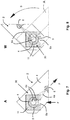
- this fact is shown in more detail in a side sectional view. In the FIG.
- the flow channel 8a of the second supply section 8 leads from below in the radial direction of the first supply section 4 and passes continuously into its flow channel 4a. Following this (perpendicular to the image plane of the FIG. 4 ) runs the Flow channel 4a in the axial direction of the first lead portion 4.
- the flow of the coating material is indicated by arrows F ( FIG. 7 ).
- the first supply section 4 and the coating nozzle 2 are shown pivoted by 90 ° relative to the working position A in the maintenance position W, s.
- Arrow S in the FIG. 8 the convex wall 5 of the first supply section 4 seals the free or open end of the flow channel 8a of the second supply section 8.
- the convex wall 5 of the first supply section 4 slides along the open end of the flow channel 8a until it is closed by the said convex wall 5.
- the flow of the coating material is stopped by the transfer of the coating nozzle 2 or 3 from the working position A to the maintenance position W - and released again in the corresponding reversing movement.
- the two coating nozzles 2, 3 in each case by means of a rotary joint 30 are pivotable about a respective pivot axis 31 (s. FIGS. 4 and 6 ), so that the coating nozzles 2, 3 from a working position A ( FIGS. 1 . 3 . 4 . 7 ) in a maintenance position W ( Figures 2 . 5 . 6 . 8th ) and are pivotable back.
- the first supply line sections 4 are rotatably mounted in each case a stationary bearing element 11 (s. FIGS. 4, 6 . 7, 8 ).
- the feeding angle is for each coating nozzle 2, 3 preferably 90 °, so that the entire angle between the two coating nozzles 2, 3 in the swung-open state (s. FIG. 5 ) Is 180 °.
- the two nozzle slots 6 are readily accessible in the maintenance position W pivoted coating nozzles 2, 3 easily accessible to remove, for example, upset fibers or filament fragments from them.
- a Knee lever device 17 is provided, the present case per coating nozzle 2 or 3 provides a toggle mechanism.
- a telescopic spring 18 is pivotally connected to a frame 19 on a frame 16.
- the telescopic spring 18 can be operated manually and / or pneumatically or hydraulically.
- the other end of the telescopic spring 18 is hinged to a lug 21 by means of a hinge 20 pivotally.
- the extension piece 21 is connected to a rod 22, one end of which is likewise pivotably articulated to the frame 16 by means of a joint 23 and the other end by means of a hinge 24 to another rod 25.
- This rod 25 in turn is articulated by means of a hinge 26 pivotally on the coating nozzle 3 (the same applies to the coating nozzle 2).
- the toggle presses the coating nozzle 3 (or 2) in the working position A.
- the telescopic spring 18 transferred to the retracted position ( FIG. 2 ), pivots the associated coating nozzle 3 and 2, including the respective first lead portion 4 by the buckling of the rod 25 relative to the rod 22 in the maintenance position W.
- This movement is reversible by extending the Teleskopfeder 18.
- the two toggle mechanisms can operate independently, so that only one of the two coating nozzles 2 or 3 is pivoted (for example, in the maintenance position W for cleaning the nozzle slot 6), while the other coating nozzle 3 or 2 remains in its current position ,
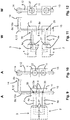
- FIGS. 9 to 12 an alternative embodiment for the realization of a relative movement of the first and second lead portion 4, 8 is shown.
- a sliding joint 35 is provided, with which the first supply line section 4 and thus also by means of a respective flange 27 at he attached coating die 2 and 3 (for better clarity, only in the FIGS. 9, 11 . 13 and 15 dashed lines) can be moved linearly in order to move them from a working position A (FIG. FIGS. 9 and 10 ) into a maintenance position W ( FIGS. 11 and 12 ).
- one of the two supply line sections 4, 8 is formed in sections in each one of two sliding bearing elements 11, each having two mutually perpendicular holes.
- the one hole forms a part of the flow channel 4a of the first lead portion 4, while the other is perpendicular to the former and forms part of the flow channel 8a of the second lead portion 8.
- the two bearing elements 11 are thus also part of the respective first lead sections 4 and part of the respective second lead sections 8.
- the two coating nozzles 2, 3 are relatively widely spaced so that they are relatively easily accessible from the underside or the side of the nozzle slots 6.
- the two coating nozzles 2, 3 form a thin gap between them, between which the flat material web 10 is passed (into the FIGS. 9 to 10 not shown; the passage direction of the flat material web runs in the image plane of the FIGS. 9 and 11 in).
- a common supply line section 12 is reproduced, which by means of a flange 14 with a storage unit (again not shown) is connectable.
- the common feed line section 12 bears this name because it supplies coating material to both coating nozzles 2, 3.
- the common supply line section 12 is also part of the second supply line section 8, with respect to which the (in the FIGS. 9 to 12 upper) second coating nozzle 3 is slidably disposed. In the extension of this common lead portion 12 this goes, after passing the upper Slide joint 35 for the second coating nozzle 3, in a sole second feed line section 8, which leads to the lower sliding joint 35 for the first coating nozzle 2.
- the entire second supply line section 8 from the flange 14 to its also the lower sliding joint 35 passing free end is formed as a rigid tube 15, along which the two rigid first lead sections 4 and the rigidly connected to their coating nozzles 2, 3 are arranged linearly displaceable.
- the free end of the respective first supply line sections 4 each seals an opening in the second supply line sections 8 in order to allow a flow through their flow channels 4a, 8a to the respective coating nozzle 2, 3 in the working position A ( FIGS. 9 and 10 ).
- the two openings of the second supply line sections 8 are sealed by the walls of the bore 15 running parallel to the pipe 15 in the bearing elements 11.
- the open to the pipe 15 facing ends of the flow channels 4a are sealed by the wall of the tube 15, so that a reflux of the coating material is prevented.
- FIGS. 13 to 16 is a further variant of a linearly displaceable arrangement of the first lead portions 4 and the rigid associated with these coating nozzles 2 and 3 (only in the FIGS. 13 and 15 and also reproduced there only in dashed lines) on the one hand and the second supply line sections 8 on the other hand.
- the corresponding push joints 40 of this embodiment are similar to the push joints 35 according to FIG FIGS. 9 to 12 educated.
- FIGS. 13 to 16 is a common supply line section 12, which is connected by means of a flange 14 to an upstream arranged storage unit (not shown) - possibly via further intermediate supply line sections - provided, branch off from the two short second lead portions 8 in opposite directions. At their ends they encounter - in the working position Ader coating nozzles 2, 4 - to the free ends of first supply line sections 4, which run at an angle of 90 ° in opposite directions to the coating nozzles 2, 3. The first supply line sections 4 and the coating nozzles 2, 3 are in turn connected to each other with flanges 27.
- each first lead portion 4 is in turn guided in a block-like bearing element 11, wherein each first lead portion 4 has an integrally connected thereto cylindrical extension piece 41 without bore, which extends in the direction away from the respective flange 27 direction.
- These extension pieces 41 seal in the maintenance position W (FIG. FIGS. 15 and 16 ) From the free open ends of the second lead portions 8 from.
- working position A FIGS. 13 and 14
- the flow channels 4a, 8a in turn allow a continuous flow of the coating material to the two coating nozzles 2, 3.
- each flow channel 4a is first formed by a parallel to the flow passage 8a extending bore in the bearing element 11, which in a perpendicular thereto lead portion 4a goes over, which is angled on its way to the coating nozzle 2 and 3 again by 90 ° until it ends in the respective flange 27.
- the invention makes it possible to produce prepregs by coating a fiber-containing flat material web 10, in particular glass or carbon filaments, by means of one of the devices described above, wherein the coating nozzles are transferred from the maintenance position W to a working position A in order to apply coating material to the moving flat material web 10.
- the present invention is not limited to the illustrated and described embodiments. Variations within the scope of the claims are also possible as a combination of features, even if they are shown and described in different embodiments. For example, it is possible to coat two or more flat material webs at the same time by two or more such flat material webs side by side through the device according to the invention.
Landscapes
- Chemical & Material Sciences (AREA)
- Engineering & Computer Science (AREA)
- Materials Engineering (AREA)
- Polymers & Plastics (AREA)
- Manufacturing & Machinery (AREA)
- Health & Medical Sciences (AREA)
- Chemical Kinetics & Catalysis (AREA)
- Medicinal Chemistry (AREA)
- Organic Chemistry (AREA)
- Inorganic Chemistry (AREA)
- Coating Apparatus (AREA)
- Mechanical Engineering (AREA)
- Application Of Or Painting With Fluid Materials (AREA)
- Reinforced Plastic Materials (AREA)
Description
- Die vorliegende Erfindung betrifft eine Vorrichtung zum beidseitigen Beschichten mindestens einer laufenden Flachmaterialbahn.
US6174372 zeigt ein gattungsgemäße Vorrichtung. - Zur Beschichtung und Verfestigung von Flachmaterialbahnen, beispielsweise flachen, nebeneinander laufenden Kohlenstofffasern bzw. Carbonfilamenten, sind Beschichtungsdüsen bekannt. Diese Beschichtungsdüsen, auch häufig als Pultrusionsdüsen bezeichnet, dienen zum Auftragen einer heißen Beschichtungsflüssigkeit, welche die Fasern benetzt und zwischen die Fasern fließt. Bei Weiterführen der Flachmaterialbahn durch einen Ofen kühlt die Beschichtungsflüssigkeit ab, wodurch die Fasern dauerhaft miteinander verkleben und somit ein verfestigtes Tape erhalten wird. Dieses kann dann aufgewickelt und in einem späteren Prozess zur Herstellung von Leichtbauteilen verwendet werden.
- Die bekannten Beschichtungsdüsen weisen flexible, beheizbare Zuleitungen auf, die aus Kunststoff bestehen und durch welche geschmolzenes Beschichtungsmaterial geführt werden kann. Die Verwendung von flexiblen Zuleitungen ist erforderlich, um die Düse während der Produktion mit nur kurzen Stillstandzeiten öffnen und reinigen zu können, da es beim Imprägnieren immer wieder zum Aufstauchen von beschädigten Fasern kommt, die dann in der oder den Beschichtungsdüsen akkumulieren. Bei Verwendung von starren Leitungen ist ein einfaches Öffnen zum Zweck der Reinigung nicht möglich.
- Die Kunststoff-Zuleitungen müssen einerseits hohe Drücke aushalten und andererseits idealerweise hohe Schmelze-Temperaturen. In beiderlei Hinsicht sind die Kunststoff-Zuleitungen jedoch nicht optimal. Beispielsweise halten sie in aller Regel lediglich einer Schmelze-Temperatur von bis zu 260 °C stand. Thermoplaste wie z.B. PA6, PET usw. mit höheren Schmelztemperaturen und erforderlichen Verarbeitungsdrücken sind damit nicht einsetzbar. Hinzu kommt noch, dass der die Schmelze führende Teil der flexiblen Zuleitung nicht glatt, sondern gewellt ist. Dies führt zu sehr unterschiedlichen Verweilzeiten der Schmelze in der Zuleitung, was einen starken thermischen Abbau von Teilen der Schmelze zur Folge hat.
- Es ist Aufgabe der vorliegenden Erfindung, eine Beschichtungsvorrichtung zur Verfügung zu stellen, die eine einfache Beschichtung und insbesondere Wartung ermöglicht und zudem gewährleistet, dass Beschichtungsmaterial ohne wesentliche Einschränkungen hinsichtlich dessen Temperatur und Druck einer Flachmaterialbahn zugeführt werden kann.
- Die Aufgabe wird gelöst durch eine Vorrichtung mit den Merkmalen des Patentanspruchs 1.
- Die erfindungsgemäße Vorrichtung bietet zum einen den Vorteil, dass starre Zuleitungsabschnitte vorgesehen sind, welche wesentlich einfacher beheizbar sind als flexible Schläuche. So können starre Zuleitungsabschnitte insbesondere aus Metall, vorzugsweise aus Edelstahl, bestehen, die von außen mit Heizeinrichtungen umgeben werden, so dass das Beschichtungsmaterial mit Temperaturen von oberhalb 260 °C durch sie hindurch fließen kann. So sind ohne weiteres Temperaturen von über 400 °C zu erreichen. Unter dem Begriff "starr" wird vorliegend eine nicht-flexible, unbewegliche Ausgestaltung verstanden, die insbesondere nicht per Hand verbiegbar ist.
- Die Erfindung ermöglicht somit, dass sehr hohe Verarbeitungstemperaturen von 300 °C und höher und hohe Verarbeitungsdrücke (ca. 200 bar) einsetzbar sind. Zudem ist eine Öffnungsbewegung der Beschichtungsdüsen in die Wartungsposition und eine Schließbewegung in deren Arbeitsposition möglich, ohne dass Halterungen oder Schrauben gelöst werden müssten.
- Ein weiterer Vorteil besteht darin, dass zumindest eine der Beschichtungsdüsen, vorzugsweise beide, von einer Arbeits- in eine Wartungsposition überführt werden kann, wobei bei diesem Überführen ein erster starrer Leitungsabschnitt relativ zu einem zweiten starren Leitungsabschnitt bewegt wird, um den Durchfluss des Beschichtungsmaterials zu stoppen. Diese Ausgestaltung hat den Vorteil, dass die mindestens eine Beschichtungsdüse zusammen mit dem ersten Zuleitungsabschnitt bewegt wird, besonders bevorzugt ohne ein zusätzliches Gelenk o.ä. zwischen der Beschichtungsdüse und dem ersten Zuleitungsabschnitt. Mit anderen Worten wird der starr ausgebildete erste Zuleitungsabschnitt zusammen mit der zugehörigen Beschichtungsdüse relativ zum zweiten, starr ausgebildeten Zuleitungsabschnitt bewegt. Vorzugsweise reicht hierbei eine einzige Bewegung, nämlich eine Relativbewegung des ersten zum zweiten Zuleitungsabschnitt, sowohl zum Überführen der mindestens einen Beschichtungsdüse von der Arbeits- in die Wartungsposition als auch zum Unterbrechen des Flusses des Beschichtungsmaterials.
- Vorzugsweise dichtet eine Wandung des ersten Zuleitungsabschnitts in der Wartungsposition der zugehörigen Beschichtungsdüse den im zweiten Zuleitungsabschnitt ausgebildeten Durchflusskanal für das Beschichtungsmaterial endseitig ab. Diese Abdichtfunktion wird vorteilhafterweise durch die Relativbewegung des ersten zum zweiten Zuleitungsabschnitt realisiert, besonders bevorzugt durch eine einzige Bewegung des ersten Zuleitungsabschnitts und der zugehörigen Beschichtungsdüse. Die Abdichtung erfolgt hierbei derart, dass kein Beschichtungsmaterial aus dem ansonsten offenen Ende des zweiten Durchflusskanals austreten kann, da die Wandung des ersten Zuleitungsabschnitts dieses Ende abdichtet. Der Vorteil liegt darin, dass in der Wartungsposition das Beschichtungsmaterial nicht in eine andere Leitung umgelenkt werden muss. Außerdem kann das Beschichtungsmaterial nicht unkontrolliert abtropfen, was eine Verletzungsgefahr darstellen würde.
- Schließlich wird durch den hermetischen Verschluss der Zuleitung verhindert, dass das Polymer oxidativ abgebaut wird.
- Wie oben ausgeführt ist es bevorzugt, wenn der besagte erste Zuleitungsabschnitt relativ zu der zugehörigen Beschichtungsdüse positionsunveränderlich ausgebildet ist. Mit anderen Worten bilden der erste Zuleitungsabschnitt und die zugehörige Beschichtungsdüse eine Einheit, die als Ganzes beim Überführen der Beschichtungsdüse von der Arbeitsposition in die Wartungsposition bewegt wird. Dieser Aufbau ist einfach und leicht handhabbar, verschafft aber gleichzeitig den Vorteil der leichten Zugänglichkeit zum Düsenschlitz der Beschichtungsdüse.
- Beim Überführen der mindestens einen Beschichtungsdüse von der Arbeitsposition in die Wartungsposition und zurück wird vorzugsweise der zweite Zuleitungsabschnitt nicht mitbewegt. Bevorzugt bewegen sich bei dem genannten Überführen tatsächlich lediglich der erste Zuleitungsabschnitt und die zugehörige Beschichtungsdüse, vorzugsweise - entsprechend den obigen Ausführungen - mit einer einzigen Bewegung.
- Besonders bevorzugt sind keine flexiblen Abschnitte zwischen der Bevorratungseinheit für das Beschichtungsmaterial und den Beschichtungsdüsen vorhanden. Mit anderen Worten sind alle das Beschichtungsmaterial führenden Zuleitungsabschnitte starr ausgebildet. Insbesondere sind hierbei auch zwischen den ersten und zweiten Zuleitungsabschnitten, die bevorzugt rotatorisch und/oder translatorisch zueinander bewegbar sind, keine flexibel ausgebildeten, d.h. nicht-starren Teile vorhanden.
- Bevorzugt ist ein gemeinsamer Zuleitungsabschnitt für beide Beschichtungsdüsen vorgesehen. Durch diesen gemeinsamen Zuleitungsabschnitt wird Beschichtungsmaterial für beide Beschichtungsdüsen geleitet, von welchem dann zwei Zuleitungsabschnitte wegführen, wobei jeweils eine dieser Zuleitungsabschnitte zu jeweils einer Beschichtungsdüse führt. Diese beiden besagten Zuleitungsabschnitte sind vorzugsweise als erste Zuleitungsabschnitte ausgebildet, die - entsprechend dem Vorgesagten - bevorzugt eine starre Einheit mit der Beschichtungsdüse bilden. Auch der gemeinsame Zuleitungsabschnitt ist besonders bevorzugt starr ausgebildet. Bei einer entsprechenden Ausführung ist ein gemeinsamer starrer Zuleitungsabschnitt vorgesehen, von dem zwei starre zweite Zuleitungsabschnitte abzweigen, die dann in jeweils in einen ersten starren Zuleitungsabschnitt übergehen, wobei entsprechend der Erfindung die ersten und zweiten Zuleitungsabschnitte relativ zueinander bewegbar sind.
- Der besagte gemeinsame Zuleitungsabschnitt ist gemäß einer vorteilhaften Ausführungsform zumindest teilweise identisch mit mindestens einem zweiten Zuleitungsabschnitt, vorzugsweise mit zwei zweiten Zuleitungsabschnitten, die jeweils mit einem ersten, zur jeweiligen Beschichtungsdüse führenden Zuleitungsabschnitt verbunden sind. Bei einer entsprechenden Ausgestaltung führt ein gemeinsamer starrer Zuleitungsabschnitt zu einem ersten starren Zuleitungsabschnitt, der relativ zum gemeinsamen Zuleitungsabschnitt bewegbar ausgebildet ist. In diesem Fall sind also der gemeinsame Zuleitungsabschnitt und der zweite Zuleitungsabschnitt - zumindest auf diesem Teilstück - identisch.
- Gemäß einer vorteilhaften Ausgestaltung sind der erste und der zweite Zuleitungsabschnitt mindestens einer und vorzugsweise beider Beschichtungsdüsen jeweils mit einem Schubgelenk miteinander verbunden. Hierbei wird bevorzugt der erste gegenüber dem zweiten Zuleitungsabschnitt verschoben, beispielsweise linear oder in einer Bogenbewegung. Wird beispielsweise der erste Zuleitungsabschnitt zusammen mit der zugehörigen Beschichtungsdüse von der Flachmaterialbahn in einer Linearbewegung vom zweiten Zuleitungsabschnitt wegbewegt, ist der Düsenschlitz der Beschichtungsdüse in einfacher Weise zugänglich.
- Die mindestens eine Beschichtungsdüse kann vorteilhafterweise insbesondere durch eine Linearbewegung von der Arbeits- in die Wartungsposition und durch eine entgegengesetzte Linearbewegung von der Wartungs- in die Arbeitsposition überführbar ausgestaltet sein. Hierbei wird auch der erste Zuleitungsabschnitt relativ zum zweiten Zuleitungsabschnitt linear verschoben. Der zweite Zuleitungsabschnitt bleibt vorzugsweise stationär bzw. ortsfest.
- Gemäß einer alternativen Ausführungsform (die ggf. jedoch auch mit der vorbeschriebenen kombinierbar ist), sind der erste und der zweite Zuleitungsabschnitt mindestens einer und vorzugsweise beider Beschichtungsdüsen jeweils mittels eines Drehgelenks miteinander verbunden. Bei dieser Schwenk- bzw. Rotationsbewegung wird der erste Zuleitungsabschnitt relativ zum zweiten, hierbei bevorzugt ortsfest bleibenden Zuleitungsabschnitt bewegt und somit besonders bevorzugt auch die mindestens eine Beschichtungsdüse von der Arbeits- in die Wartungsposition und durch eine entgegengesetzte Rotationsbewegung von der Wartungs- in die Arbeitsposition überführt.
- Bei einer diesbezüglich bevorzugten Ausführungsform sind die im ersten und zweiten Zuleitungsabschnitt ausgebildeten Durchflusskanäle in der Arbeitsposition der zugehörigen Beschichtungsdüse radial miteinander fluchtend in dem Drehgelenk ausgebildet. Bei einem Überführen dieser Beschichtungsdüse von der Arbeitsposition in die Wartungsposition wird der erste Zuleitungsabschnitt relativ zum zweiten Zuleitungsabschnitt in Umfangsrichtung des Drehgelenks rotatorisch verschoben, so dass der Durchfluss des Beschichtungsmaterials unterbrochen wird. Das freie Ende des zweiten Zuleitungsabschnitts, das in der Arbeitsposition der Beschichtungsdüse in ein freies Ende des ersten Zuleitungsabschnitts übergeht, wird hierbei in der Wartungsposition vorzugsweise durch eine konvexe Wandung des ersten Zuleitungsabschnitts abgedichtet.
- Bei der vorgenannten Ausführungsform ist es bevorzugt, wenn der Durchflusskanal des zweiten Zuleitungsabschnitts in Durchflussrichtung radial von außen nach innen zum ersten Zuleitungsabschnitt geführt ist. Der innen liegende erste Zuleitungsabschnitt, der dann vorzugsweise vom zweiten Zuleitungsabschnitt umschlossen ist, dreht sich dann innerhalb dieses zweiten Zuleitungsabschnitts, während der letztere vorzugsweise ortsfest ist.
- Eine vorteilhafte Ausgestaltung des ersten Zuleitungsabschnitts sieht vor, dass der darin vorgesehene Durchflusskanal zunächst, d.h. im Anschluss an den Übergang vom zweiten Zuleitungsabschnitt, in Durchflussrichtung radial in Bezug auf die Drehachse des Drehgelenks und nachfolgend in Axialrichtung des Drehgelenks, vorzugsweise die Längsachse einschließend, in Richtung der Beschichtungsdüse führt. Diese Ausgestaltung ist beispielsweise in einfacher Weise durch zwei senkrecht zueinander verlaufende und ineinander übergehende Bohrungen in dem vorzugsweise als Block ausgebildeten ersten Zuleitungsabschnitt realisierbar.
- Bei einer vorteilhaften Ausgestaltung der erfindungsgemäßen Vorrichtung ist eine Kniehebeleinrichtung zum Überführen mindestens einer der Beschichtungsdüsen von der Arbeitsposition in die Wartungsposition vorgesehen. Der Hebelmechanismus des Kniehebels ermöglicht es, ein schnelles und kraftvolles Schließen (Überführen von der Wartungsposition in die Arbeitsposition) und Öffnen (Überführen von der Arbeitsposition in die Wartungsposition) ausführen zu können. Die Kniehebeleinrichtung ist vorzugsweise manuell und/oder pneumatisch oder hydraulisch betätigbar.
- Besonders bevorzugt sind die beiden Beschichtungsdüsen in ihrer jeweiligen Arbeitsposition sich gegenüberliegend angeordnet, wobei die zu beschichtende Flachmaterialbahn zwischen den Düsenschlitzen läuft. Die beiden Beschichtungsdüsen sowie deren zugehöriger erster und zweiter Zuleitungsabschnitt können insbesondere symmetrisch (wobei die Symmetrieebene durch die Transportebene der Flachmaterialbahn definiert ist) und mittels gleicher Kinematik, beispielsweise einer vorgenannten Kniehebeleinrichtung mit zwei Kniehebeln, ausgebildet sein. Die obigen Ausführungen, insbesondere hinsichtlich der Dreh- oder Schubgelenke bzw. der Relativbewegungen von dem jeweiligen ersten zum jeweiligen zweiten Zuleitungsabschnitt, gelten dann besonders bevorzugt für beide Beschichtungsdüsen. Die beiden Beschichtungsdüsen können insbesondere gegenläufig zueinander aus ihrer jeweiligen Arbeitsposition in ihre Wartungsposition und zurück überführbar sein.
- Die erfindungsgemäße Vorrichtung ist gemäß der vorangegangenen Beschreibung ausgebildet, wobei die genannten Merkmale einzeln oder in beliebiger Kombination vorhanden sein können.
- Die Erfindung betrifft ebenfalls ein Verfahren zum Herstellen von Prepregs (preimpregnated fibres, vorimprägnierte Fasern) durch Beschichten einer faserhaltigen Flachmaterialbahn, insbesondere aus Glas- oder Carbonfilamenten, mittels der vorbeschriebenen Vorrichtung, wobei die Beschichtungsdüsen von einer Wartungsposition in eine Arbeitsposition überführt werden, um Beschichtungsmaterial auf eine laufende Flachmaterialbahn aufzutragen.
- Weitere Vorteile der Erfindung sind in den nachfolgenden Ausführungsbeispielen beschrieben. Es zeigen:
- Figur 1
- eine Seitenansicht einer erfindungsgemäßen Vorrichtung mit zwei in Arbeitsposition befindlichen Beschichtungsdüsen, die gegeneinander mittels einer Kniehebeleinrichtung verschwenkbar sind;
- Figur 2
- eine Seitenansicht der Vorrichtung der
Figur 1 in Wartungsposition; - Figur 3
- eine Seitenansicht der beiden Beschichtungsdüsen der
Figuren 1 und 2 , in Arbeitsstellung (um 90° gegenüber der Darstellung inFigur 1 gedreht); - Figur 4
- eine Draufsicht auf die beiden Beschichtungsdüsen der
Figur 3 , in Arbeitsstellung; - Figur 5
- eine Seitenansicht der beiden Beschichtungsdüsen der
Figuren 3 und 4 , in Wartungsstellung; - Figur 6
- eine Draufsicht auf die beiden Beschichtungsdüsen der
Figuren 3 bis 5 , in Wartungsstellung; - Figur 7
- eine geschnittene Seitenansicht einer Beschichtungsdüse der
Figuren 3-6 , in Arbeitsstellung; - Figur 8
- eine geschnittene Seitenansicht einer Beschichtungsdüse wie in
Figur 7 , allerdings in Wartungsstellung; - Figur 9
- eine Seitenansicht einer Vorrichtung mit zwei gegeneinander linear verschiebbaren, in Arbeitsstellung befindlichen Beschichtungsdüsen (gestrichelt dargestellt);
- Figur 10
- eine Vorderansicht auf die Vorrichtung der
Figur 9 (Beschichtungsdüsen nicht dargestellt); - Figur 11
- eine Seitenansicht der Vorrichtung der
Figuren 8 und9 mit in Wartungsstellung verschobenen Beschichtungsdüsen (gestrichelt dargestellt); - Figur 12
- eine Vorderansicht auf die Vorrichtung der
Figur 11 (Beschichtungsdüsen nicht dargestellt); - Figur 13
- eine Hinteransicht einer alternativen Vorrichtung mit zwei gegeneinander linear verschiebbaren, in Arbeitsstellung befindlichen Beschichtungsdüsen (gestrichelt dargestellt);
- Figur 14
- eine Seitenansicht der Vorrichtung der
Figur 13 (Beschichtungsdüsen nicht dargestellt); - Figur 15
- eine Hinteransicht wie in
Figur 13 , allerdings mit linear gegeneinander verschobenen Zuleitungsabschnitten (Beschichtungsdüsen gestrichelt dargestellt), und - Figur 16
- eine Seitenansicht der Vorrichtung der
Figur 15 (Beschichtungsdüsen nicht dargestellt); - Bei der nachfolgenden Beschreibung werden für gleiche Merkmale, die bei unterschiedlichen Ausführungsformen in ihrer Ausgestaltung und/oder Wirkweise identisch und/oder zumindest vergleichbar sind, gleiche Bezugszeichen verwendet. Sofern diese nicht nochmals detailliert erläutert werden, entspricht deren Ausgestaltung und/oder Wirkweise der Ausgestaltung und/oder Wirkweise der vorstehend bereits beschriebenen Merkmale.
- Die
Figuren 1 und 2 zeigen in Seitenansicht eine Vorrichtung 1 mit zwei Beschichtungsdüsen 2, 3, die in denFiguren 3 bis 6 in Alleindarstellung wiedergegeben sind. Die Beschichtungsdüsen 2, 3 sind in derFigur 1 in einer Arbeitsstellung A dargestellt, in der sich ihre Düsenschlitze 6 gegenüberliegen und eine Flachmaterialbahn 10 zwischen ihnen hindurch geführt wird. Die Flachmaterialbahn 10 besteht beispielsweise aus parallel verlaufenden Carbonfilamenten, die miteinander verklebt werden sollen. Hierzu wird ein geschmolzenes Beschichtungsmaterial, beispielsweise ein Polyamid (z.B. PA6) oder Polyester (PET), mit einer Temperatur von ca. 300 °C und höher und hohem Verarbeitungsdruck (z.B. bei 200 bar) mittels der Beschichtungsdüsen 2, 3 auf die laufende Flachmaterialbahn 10 von deren beider Seiten aufgetragen. Nach Verlassen der Beschichtungsdüsen 2, 3 erkaltet das Beschichtungsmaterial und verfestigt hierbei die Flachmaterialbahn 10, welche dann zur Herstellung von insbesondere dreidimensionalen Werkstücken weiterverarbeitet werden kann. - Zum Zuführen des flüssigen Beschichtungsmaterials weist das Ausführungsbeispiel der
Figuren 1-8 einen gemeinsamen Zuleitungsabschnitt 12 auf, der mittels eines Flansches 14 an einen vorgeordneten Zuleitungsabschnitt angeschlossen ist, der zu einer Bevorratungseinheit für das Beschichtungsmaterial führt (nicht dargestellt). Stromabwärtig zweigen vom gemeinsamen Zuleitungsabschnitt 12 zwei zweite Zuleitungsabschnitte 8 ab, die zusammen mit dem gemeinsamen Zuleitungsabschnitt 12 T-förmig ausgebildet sind. Am stromabwärtigen Ende jedes zweiten Zuleitungsabschnittes 8 ist ein erster Zuleitungsabschnitt 4 vorgesehen, wobei der jeweilige erste und zweite Zuleitungsabschnitt 4, 8 jeweils mittels eines Drehgelenks 30, das weiter unten beschrieben wird, miteinander verbunden sind. Der jeweilige erste Zuleitungsabschnitt 4 führt zu der Beschichtungsdüse 2 bzw. der Beschichtungsdüse 3, die jeweils einen Düsenschlitz 6 aufweisen, welcher der Flachmaterialbahn 10 in der Arbeitsposition A zugestellt werden kann. - Die ersten und zweiten Zuleitungsabschnitte 4, 8 sowie auch der gemeinsame Zuleitungsabschnitt 12 sind starr, d.h. nicht flexibel, ausgebildet, vorzugsweise aus einem Metall und insbesondere aus Edelstahl. Sie weisen Durchflusskanäle 4a, 8a und 12a auf, die bei in Arbeitsstellung A verschwenkter Position einen von der Bevorratungseinheit bis zu den Düsenschlitzen 6 durchgehenden Fluss an Beschichtungsmaterial ermöglichen. Hierzu werden zumindest einige der Zuleitungsabschnitte 4, 8, 12 zumindest abschnittsweise mit Heizeinrichtungen, beispielsweise Heizdrähten, umgeben (nicht dargestellt). Die Zuleitungsabschnitte aus bevorzugt Edelstahl leiten die Wärme hervorragend, so dass das durch sie hindurchfließende Beschichtungsmaterial problemlos im geschmolzenen Zustand gehalten werden kann. Angemerkt sei, dass entsprechende Heizeinrichtungen auch bei den Vorrichtungen der übrigen Ausführungsbeispiele (
Figuren 9 bis 12 undFiguren 13-16 ) vorgesehen sind. - Des Weiteren ist jeder der beiden ersten Zuleitungsabschnitte 4 starr mit der jeweiligen Beschichtungsdüse 2 bzw. 3 verbunden, beispielsweise durch Verschweißung oder Verschraubung, so dass nur eine gemeinsame Bewegung von jeweiligem ersten Zuleitungsabschnitt 4 und Beschichtungsdüse 2 bzw. 3 möglich ist. Die zweiten Zuleitungsabschnitte 8 hingegen bleiben stets in ihrer Position; nur der jeweilige erste Zuleitungsabschnitt 4 und die zugehörige Beschichtungsdüse 2 bzw. 3 werden beim Überführen von der Arbeitsposition A in die Wartungsposition W und zurück bewegt.
- In der Arbeitsstellung A sind der jeweilige erste und zweite Zuleitungsabschnitt 4, 8 derart zueinander ausgerichtet, dass deren Durchflusskanäle 4a, 8a aneinander anschließen, um den Durchfluss des Beschichtungsmaterials zur jeweiligen Beschichtungsdüse 2, 3 zu ermöglichen. Hierzu ist gemäß dem vorliegenden Ausführungsbeispiel der Durchflusskanal 8a des zweiten Zuleitungsabschnitts 8 in Durchflussrichtung radial von außen nach innen zum ersten Zuleitungsabschnitt 4 geführt. Anschließend - in Durchflussrichtung gesehen - weist der Durchflusskanal 4a eine 90°-Krümmung auf und läuft in Axialrichtung des Durchflusskanals 4a, um dann - wiederum nach einer 90°-Krümmung - in dem Düsenschlitz 6 zu münden. In den
Figuren 7 und 8 ist dieser Sachverhalt genauer in einer seitlichen Schnittansicht dargestellt. In derFigur 7 führt der Durchflusskanal 8a des zweiten Zuleitungsabschnitts 8 von unten in Radialrichtung des ersten Zuleitungsabschnitts 4 und geht durchgehend in dessen Durchflusskanal 4a über. Im Anschluss daran (senkrecht zur Bildebene derFigur 4 ) verläuft der Durchflusskanal 4a in Axialrichtung des ersten Zuleitungsabschnitts 4. Der Fluss des Beschichtungsmaterials ist mit Pfeilen F (Figur 7 ) gekennzeichnet. - In der
Figur 8 sind der erste Zuleitungsabschnitt 4 und die Beschichtungsdüse 2 um 90° gegenüber der Arbeitsposition A in die Wartungsposition W verschwenkt dargestellt, s. Pfeil S in derFigur 8 . Bei diesem Verschwenken dichtet die konvexe Wandung 5 des ersten Zuleitungsabschnitts 4 das freie bzw. offene Ende des Durchflusskanals 8a des zweiten Zuleitungsabschnitts 8 ab. Hierbei gleitet die konvexe Wandung 5 des ersten Zuleitungsabschnitts 4 entlang dem offenen Ende des Durchflusskanals 8a, bis dieser von der besagten konvexen Wandung 5 verschlossen ist. Somit wird der Fluss des Beschichtungsmaterials durch das Überführen der Beschichtungsdüse 2 bzw. 3 von der Arbeitsposition A in die Wartungsposition W gestoppt - und bei der entsprechenden Umkehrbewegung wieder freigegeben. - Wie oben angedeutet, sind die beiden Beschichtungsdüsen 2, 3 jeweils mittels eines Drehgelenks 30 um jeweils eine Schwenkachse 31 verschwenkbar ausgebildet (s.
Figuren 4 und 6 ), so dass die Beschichtungsdüsen 2, 3 von einer Arbeitsstellung A (Figuren 1 ,3 ,4 ,7 ) in eine Wartungsstellung W (Figuren 2 ,5 ,6 ,8 ) und zurück verschwenkbar sind. Hierzu sind die ersten Zuleitungsabschnitte 4 in je einem ortsfesten Lagerelement 11 drehbar gelagert (s.Figuren 4, 6 ,7, 8 ). Der Schenkwinkel beträgt für jede Beschichtungsdüse 2, 3 vorzugsweise 90°, so dass der gesamte Winkel zwischen den beiden Beschichtungsdüsen 2, 3 im aufgeschwenkten Zustand (s.Figur 5 ) 180° beträgt. Wie insbesondere denFiguren 2 und5 zu entnehmen ist, sind die beiden Düsenschlitze 6 bei in Wartungsposition W verschwenkten Beschichtungsdüsen 2, 3 ohne weiteres bequem zugänglich, um beispielsweise aufgestauchte Fasern bzw. Filamentbruchstücke aus ihnen zu entfernen. - Um die genannte Schwenkbewegung zu realisieren, ist eine Kniehebeleinrichtung 17 vorgesehen, die vorliegend pro Beschichtungsdüse 2 bzw. 3 eine Kniehebelmechanik vorsieht. Hierzu ist an einem Gestell 16 jeweils eine Teleskopfeder 18 an einem Gelenk 19 schwenkbar angelenkt. Die Teleskopfeder 18 kann manuell und/oder pneumatisch oder hydraulisch betätigt werden. Das andere Ende der Teleskopfeder 18 ist an einem Ansatzstück 21 mittels eines Gelenks 20 schwenkbar angelenkt. Das Ansatzstück 21 ist mit einer Stange 22 verbunden, deren eines Ende ebenfalls an dem Gestell 16 mittels eines Gelenks 23 und deren anderes Ende mittels eines Gelenks 24 an einer weiteren Stange 25 schwenkbar angelenkt ist. Diese Stange 25 wiederum ist mittels eines Gelenks 26 schwenkbar an der Beschichtungsdüse 3 (Analoges gilt für die Beschichtungsdüse 2) angelenkt. In der
Figur 1 befindet sich die Teleskopfeder 18 im ausgefahrenen Zustand, wobei der Kniehebel die Beschichtungsdüse 3 (bzw. 2) in die Arbeitsstellung A presst. Wird die Teleskopfeder 18 in die eingefahrene Stellung überführt (Figur 2 ), schwenkt die zugehörige Beschichtungsdüse 3 bzw. 2 einschließlich des jeweiligen ersten Zuleitungsabschnitts 4 durch das Einknicken der Stange 25 relativ zur Stange 22 in die Wartungsposition W. Diese Bewegung ist durch Ausfahren der Teleskopfeder 18 reversibel. - Wie zudem den
Figuren 1 und 2 zu entnehmen ist, können die beiden Kniehebelmechanismen unabhängig voneinander arbeiten, so dass auch nur eine der beiden Beschichtungsdüsen 2 oder 3 verschwenkt wird (beispielsweise in die Wartungsposition W zum Reinigen des Düsenschlitzes 6), während die andere Beschichtungsdüse 3 oder 2 in ihrer momentanen Position verbleibt. - In den
Figuren 9 bis 12 ist eine alternative Ausführungsform für die Realisierung einer Relativbewegung von erstem und zweitem Zuleitungsabschnitt 4, 8 dargestellt. Statt eines Drehgelenks 30 (Figuren 1 bis 8 ) ist ein Schubgelenk 35 vorgesehen, mit dem der erste Zuleitungsabschnitt 4 und damit auch die mittels je eines Flansches 27 an ihm befestigte Beschichtungsdüse 2 bzw. 3 (der besseren Übersichtlichkeit halber nur in denFiguren 9, 11 ,13 und 15 gestrichelt dargestellt) linear verschoben werden können, um sie von einer Arbeitsposition A (Figuren 9 und 10 ) in eine Wartungsposition W (Figuren 11 und 12 ) zu überführen. Hierzu ist jeweils eines der beiden Zuleitungsabschnitte 4, 8 abschnittsweise in je einem von zwei Gleit-Lagerelementen 11 ausgebildet, die jeweils zwei zueinander senkrechte Bohrungen aufweisen. Die eine Bohrung bildet einen Teil des Durchflusskanals 4a des ersten Zuleitungsabschnitts 4 aus, während die andere senkrecht zu der erstgenannten verläuft und einen Teil des Durchflusskanals 8a des zweiten Zuleitungsabschnitts 8 ausbildet. Die beiden Lagerelemente 11 sind somit auch Teil der jeweiligen ersten Zuleitungsabschnitte 4 und Teil der jeweiligen zweiten Zuleitungsabschnitte 8. - In der Wartungsposition W sind die beiden Beschichtungsdüsen 2, 3 relativ weit voneinander beabstandet, so dass sie von der Unterseite bzw. der Seite der Düsenschlitze 6 relativ leicht zugänglich sind. In der Arbeitsposition A bilden die beiden Beschichtungsdüsen 2, 3 einen dünnen Spalt zwischen sich aus, zwischen denen die Flachmaterialbahn 10 hindurchgeführt wird (in den
Figuren 9 bis 10 nicht dargestellt; die Durchlaufrichtung der Flachmaterialbahn verläuft in die Bildebene derFiguren 9 und 11 hinein). - In der Seitenansicht der
Figur 9 und der Vorderansicht derFigur 10 ist ein gemeinsamer Zuleitungsabschnitt 12 wiedergegeben, der mittels eines Flansches 14 mit einer Bevorratungseinheit (wiederum nicht dargestellt) verbindbar ist. Der gemeinsame Zuleitungsabschnitt 12 trägt diesen Namen, weil er Beschichtungsmaterial zu beiden Beschichtungsdüsen 2, 3 zuführt. Im gezeigten Ausführungsbeispiel ist der gemeinsame Zuleitungsabschnitt 12 auch Teil des zweiten Zuleitungsabschnitts 8, gegenüber dem die (in denFiguren 9 bis 12 obere) zweite Beschichtungsdüse 3 verschiebbar angeordnet ist. In der Verlängerung dieses gemeinsamen Zuleitungsabschnitts 12 geht dieser, nach Passieren des oberen Schubgelenks 35 für die zweite Beschichtungsdüse 3, in einen alleinigen zweiten Zuleitungsabschnitt 8 über, der zu dem unteren Schubgelenk 35 für die erste Beschichtungsdüse 2 führt. Der gesamte zweite Zuleitungsabschnitt 8 vom Flansch 14 bis zu seinem auch das untere Schubgelenk 35 passierenden freien Ende ist als starres Rohr 15 ausgebildet, entlang dem die beiden starren ersten Zuleitungsabschnitte 4 und die mit ihr starr verbundenen Beschichtungsdüsen 2, 3 linear verschiebbar angeordnet sind. - Das freie Ende der jeweiligen ersten Zuleitungsabschnitte 4 dichtet je eine Öffnung in den zweiten Zuleitungsabschnitten 8 ab, um einen Durchfluss durch deren Durchflusskanäle 4a, 8a zur jeweiligen Beschichtungsdüse 2, 3 in der Arbeitsposition A zu ermöglichen (
Figuren 9 und 10 ). Beim Verschieben der Beschichtungsdüsen 2, 3 nach unten bzw. nach oben werden die beiden Öffnungen der zweiten Zuleitungsabschnitte 8 durch die Wandungen der zum Rohr 15 parallel laufenden Bohrung in den Lagerelementen 11 abgedichtet. Die offenen zu dem Rohr 15 weisenden Enden der Durchflusskanäle 4a werden hingegen durch die Wandung des Rohrs 15 abgedichtet, so dass ein Rückfluss des Beschichtungsmaterials unterbunden wird. - In den
Figuren 13 bis 16 ist eine weitere Variante einer linear verschiebbaren Anordnung der ersten Zuleitungsabschnitte 4 sowie der starr mit diesen verbundenen Beschichtungsdüsen 2 bzw. 3 (nur in denFiguren 13 und 15 und auch dort nur in gestrichelten Linien wiedergegeben) einerseits und der zweiten Zuleitungsabschnitte 8 andererseits dargestellt. Die entsprechenden Schubgelenke 40 dieser Ausführungsform sind ähnlich zu den Schubgelenken 35 gemäß derFiguren 9 bis 12 ausgebildet. - Entsprechend dem Ausführungsbeispiel der
Figuren 13 bis 16 ist ein gemeinsamer Zuleitungsabschnitt 12, der mittels eines Flansches 14 an eine stromaufwärtig angeordnete Bevorratungseinheit (nicht dargestellt) - ggf. über weitere zwischengeschaltete Zuleitungsabschnitte - angeschlossen ist, vorgesehen, von dem zwei kurze zweite Zuleitungsabschnitte 8 in entgegengesetzte Richtungen abzweigen. An deren Enden stoßen sie - in der Arbeitsposition Ader Beschichtungsdüsen 2, 4 - an die freien Enden von ersten Zuleitungsabschnitten 4, die in einem Winkel von 90° in entgegengesetzte Richtungen zu den Beschichtungsdüsen 2, 3 laufen. Die ersten Zuleitungsabschnitte 4 und die Beschichtungsdüsen 2, 3 sind wiederum mit Flanschen 27 miteinander verbunden. - Die beiden ersten Zuleitungsabschnitte 4 sind wiederum in einem blockartigen Lagerelement 11 geführt, wobei jeder erste Zuleitungsabschnitt 4 ein mit ihm einstückig verbundenes zylindrisches Verlängerungsstück 41 ohne Bohrung aufweist, das sich in der dem jeweiligen Flansch 27 abgewandten Richtung erstreckt. Diese Verlängerungsstücke 41 dichten in der Wartungsposition W (
Figuren 15 und 16 ) die freien offenen Enden der zweiten Zuleitungsabschnitte 8 ab. In der Arbeitsposition A (Figuren 13 und 14 ) hingegen ermöglichen die Durchflusskanäle 4a, 8a wiederum einen durchgehenden Fluss des Beschichtungsmaterials zu den beiden Beschichtungsdüsen 2, 3. Hierzu ist jeder Durchflusskanal 4a zunächst durch eine parallel zum Durchflusskanal 8a verlaufende Bohrung in dem Lagerelement 11 gebildet, welche in einen senkrecht dazu verlaufenden Zuleitungsabschnitt 4a übergeht, der auf seinem Weg zur Beschichtungsdüse 2 bzw. 3 noch einmal um 90° abgewinkelt ist, bis er im jeweiligen Flansch 27 endet. - Sämtliche Passungen in dem Bereich der zueinander drehenden oder schiebenden Teile sind so eng und mit einer solch glatten Oberflächenqualität gestaltet, dass aufgrund der engen Spalte bei der gegebenen Viskosität der Schmelze eine Abdichtung gewährleistet ist.
- Zum Ausführungsbeispiel der
Figuren 13 bis 16 ist zu erwähnen, dass Teile der Zuleitungsabschnitte 4, 8 und 12 in dem Lagerelement 11 ausgebildet sind. - Die Erfindung ermöglicht es, Prepregs durch Beschichten einer faserhaltigen Flachmaterialbahn 10, insbesondere aus Glas- oder Carbonfilamenten, mittels einer der vorbeschriebenen Vorrichtungen herzustellen, wobei die Beschichtungsdüsen von der Wartungsposition W in eine Arbeitsposition A überführt werden, um Beschichtungsmaterial auf die laufende Flachmaterialbahn 10 aufzutragen.
- Die vorliegende Erfindung ist nicht auf die dargestellten und beschriebenen Ausführungsbeispiele beschränkt. Abwandlungen im Rahmen der Patentansprüche sind ebenso möglich wie eine Kombination der Merkmale, auch wenn diese in unterschiedlichen Ausführungsbeispielen dargestellt und beschrieben sind. Beispielsweise ist es möglich, zwei oder mehr Flachmaterialbahnen gleichzeitig zu beschichten, indem zwei oder mehr solcher Flachmaterialbahnen nebeneinander die erfindungsgemäße Vorrichtung durchlaufen.
-
- 1
- Vorrichtung
- 2
- erste Beschichtungsdüse
- 3
- zweite Beschichtungsdüse
- 4
- erster Zuleitungsabschnitt
- 4a
- Durchflusskanal
- 5
- konvexe Wandung
- 6
- Düsenschlitz
- 8
- zweiter Zuleitungsabschnitt
- 8a
- Durchflusskanal
- 10
- Flachmaterialbahn
- 11
- Lagerelement
- 12
- gemeinsamer Zuleitungsabschnitt
- 12a
- gemeinsamer Durchflusskanal
- 14
- Flansch
- 15
- Rohr
- 16
- Gestell
- 17
- Kniehebeleinrichtung
- 18
- Teleskopfeder
- 19
- Gelenk
- 20
- Gelenk
- 21
- Ansatzstück
- 22
- Stange
- 23
- Gelenk
- 24
- Gelenk
- 25
- Stange
- 26
- Gelenk
- 27
- Flansch
- 30
- Drehgelenk
- 31
- Schwenkachse
- 35
- Schubgelenk
- 40
- Schubgelenk
- 41
- Verlängerungsstück
- A
- Arbeitsposition
- W
- Wartungsposition
- F
- Fluss des Beschichtungsmaterials
- S
- Schwenkbewegung
Claims (18)
- Vorrichtung zum beidseitigen Beschichten mindestens einer laufenden Flachmaterialbahn (10),- mit einer ersten und einer zweiten Beschichtungsdüse (2, 3),wobei die erste Beschichtungsdüse (2) der ersten Seite der Flachmaterialbahn (10) und die zweite Beschichtungsdüse (3) der zweiten Seite der Flachmaterialbahn (10) zustellbar ist, um die jeweilige Seite der Flachmaterialbahn (10) zu beschichten, undwobei zumindest eine, vorzugsweise beide, Beschichtungsdüsen (2, 3) von einer Arbeits- in eine Wartungsposition (A, W) und zurück überführbar sind, sowie- mit Zuleitungsabschnitten (4, 8) mit in ihnen ausgebildeten und in der Arbeitsposition (A) miteinander verbundenen, einen Durchfluss gewährleistenden Durchflusskanälen (4a, 8a) zum Zuführen eines heißen, flüssigen Beschichtungsmaterials zu der jeweiligen Beschichtungsdüse (2, 3),
dadurch gekennzeichnet, dass durch das Überführen mindestens einer der besagten Beschichtungsdüsen (2, 3) von der Arbeits- in die Wartungsposition (A, W) automatisch ein erster starrer und ein zweiter starrer Zuleitungsabschnitt (4, 8), die in der Arbeitsposition (A) einen Durchfluss des Beschichtungsmaterials zur Beschichtungsdüse (2, 3) ermöglichen, relativ zueinander derart bewegt werden, dass die in ihnen ausgebildeten Durchflusskanäle (4a, 8a) relativ zueinander bewegt werden, um den Durchfluss des Beschichtungsmaterials zu dieser Beschichtungsdüse (2, 3) zu unterbrechen. - Vorrichtung nach Anspruch 1, dadurch gekennzeichnet, dass der im zweiten Zuleitungsabschnitt (8) ausgebildete Durchflusskanal (8a) für das Beschichtungsmaterial beim Überführen der zugehörigen Beschichtungsdüse von der Arbeits- in die Wartungsposition (A, W) endseitig durch eine Wandung des ersten Zuleitungsabschnitts (4) abgedichtet wird.
- Vorrichtung nach einem der Ansprüche 1 oder 2, dadurch gekennzeichnet, dass der besagte erste Zuleitungsabschnitt (4) relativ zur zugehörigen Beschichtungsdüse (2, 3) positionsunveränderlich ausgebildet ist und beim Überführen dieser Beschichtungsdüse (2, 3) von der Arbeitsposition (A) in die Wartungsposition (W) mitbewegt wird.
- Vorrichtung nach einem der Ansprüche 1 oder 2, dadurch gekennzeichnet, dass der besagte zweite Zuleitungsabschnitt (8) derart ausgebildet ist, dass er beim Überführen einer oder beider Beschichtungsdüsen (2, 3) von der Arbeitsposition (A) in die Wartungsposition (W) und zurück nicht mitbewegt wird.
- Vorrichtung nach einem der Ansprüche 1 oder 2, dadurch gekennzeichnet, dass alle von einer Bevorratungseinheit für das Beschichtungsmaterial zu den Beschichtungsdüsen (2, 3) führenden Zuleitungsabschnitte (4, 8, 12) starr ausgebildet sind.
- Vorrichtung nach einem der Ansprüche 1 oder 2, dadurch gekennzeichnet, dass ein gemeinsamer Zuleitungsabschnitt (12) für beide Beschichtungsdüsen (2, 3) vorgesehen ist, von dem zwei Zuleitungsabschnitte (8) wegführen, wobei jeweils einer dieser Zuleitungsabschnitte (8) zu jeweils einer Beschichtungsdüse (2, 3) führt.
- Vorrichtung nach Anspruch 6, dadurch gekennzeichnet, dass der gemeinsame Zuleitungsabschnitt (12) und mindestens ein zweiter Zuleitungsabschnitt (8), zumindest teilweise, identisch sind.
- Vorrichtung nach einem der Ansprüche 1 oder 2, dadurch gekennzeichnet, dass der erste und der zweite Zuleitungsabschnitt (4, 8) über ein Drehgelenk (30) miteinander verbunden sind.
- Vorrichtung nach Anspruch 8, dadurch gekennzeichnet, dass die mindestens eine Beschichtungsdüse (2, 3) durch eine Rotationsbewegung von der Arbeits- in die Wartungsposition (A, W) und durch eine entgegengesetzte Rotationsbewegung von der Wartungs- in die Arbeitsposition (W, A) überführbar ist, wobei auch der erste Zuleitungsabschnitt (4) relativ zum zweiten Zuleitungsabschnitt (8) rotatorisch bewegt wird.
- Vorrichtung nach Anspruch 9, dadurch gekennzeichnet, dass die im ersten und zweiten Zuleitungsabschnitt (4, 8) ausgebildeten Durchflusskanäle (4a, 8a) für das Beschichtungsmaterial in der Arbeitsposition (A) der mindestens einen Beschichtungsdüse (2, 3) radial miteinander fluchtend ausgebildet sind und dass beim Überführen der zugehörigen Beschichtungsdüse (2, 3) von der Arbeitsposition (A) in die Wartungsposition (W) der erste und der zweite Zuleitungsabschnitt (4, 8) in Umfangsrichtung des Drehgelenks (30) gegeneinander bewegt werden.
- Vorrichtung nach Anspruch 10, dadurch gekennzeichnet, dass der Durchflusskanal (8a) des zweiten Zuleitungsabschnitts (8) in Durchflussrichtung radial von außen nach innen zum ersten Zuleitungsabschnitt (4) geführt ist.
- Vorrichtung nach Anspruch 11, dadurch gekennzeichnet, dass der Durchflusskanal (4a) im ersten Zuleitungsabschnitt (4) in Durchflussrichtung radial in Bezug auf die Drehachse (31) des Drehgelenks (30) und dann in Axialrichtung zur Beschichtungsdüse (2, 3) führt.
- Vorrichtung nach einem der Ansprüche 1 oder 2, dadurch gekennzeichnet, dass eine Kniehebeleinrichtung (17), vorzugsweise manuell betätigbar und/oder pneumatisch oder hydraulisch unterstützt, zum Überführen mindestens einer der Beschichtungsdüsen (2, 3) von der Arbeitsposition (A) in die Wartungsposition (W) vorgesehen ist.
- Vorrichtung nach einem der Ansprüche 1 oder 2, dadurch gekennzeichnet, dass der erste und der zweite Zuleitungsabschnitt (4, 8) über ein Schubgelenk (35; 40) miteinander verbunden sind.
- Vorrichtung nach Anspruch 14, dadurch gekennzeichnet, dass mindestens eine Beschichtungsdüse (2, 3) durch eine Linearbewegung von der Arbeits- in die Wartungsposition (A, W) und durch eine entgegengesetzte Linearbewegung von der Wartungs- in die Arbeitsposition (W, A) überführbar ist, wobei auch der erste Zuleitungsabschnitt (4) relativ zum zweiten Zuleitungsabschnitt (8) linear verschoben wird.
- Vorrichtung nach Anspruch 1 oder 2, dadurch gekennzeichnet, dass die beiden Beschichtungsdüsen (2, 3) in ihrer jeweiligen Arbeitsposition (A) sich gegenüberliegend angeordnet sind.
- Vorrichtung nach einem der Ansprüche 1 oder 2, dadurch gekennzeichnet, dass die beiden Beschichtungsdüsen (2, 3) gegenläufig zueinander aus ihrer jeweiligen Arbeitsposition (A) in ihre Wartungsposition (W) und zurück überführbar sind.
- Verfahren zum Herstellen von Prepregs durch Beschichten einer faserhaltigen Flachmaterialbahn (10), insbesondere aus Glas- oder Carbonfilamenten, mittels einer Vorrichtung (1) nach mindestens einem der Ansprüche 1 oder 2, wobei die Beschichtungsdüsen (2, 3) von einer Wartungsposition (W) in eine Arbeitsposition (A) überführt werden, um Beschichtungsmaterial auf eine laufende Flachmaterialbahn (10) aufzutragen.
Applications Claiming Priority (2)
| Application Number | Priority Date | Filing Date | Title |
|---|---|---|---|
| DE102015112659.1A DE102015112659A1 (de) | 2015-07-31 | 2015-07-31 | Vorrichtung zum beidseitigen Beschichten mindestens einer laufenden Flachmaterialbahn |
| PCT/EP2016/066397 WO2017021102A1 (de) | 2015-07-31 | 2016-07-11 | Vorrichtung zum beidseitigen beschichten mindestens einer laufenden flachmaterialbahn |
Publications (2)
| Publication Number | Publication Date |
|---|---|
| EP3328555A1 EP3328555A1 (de) | 2018-06-06 |
| EP3328555B1 true EP3328555B1 (de) | 2019-10-09 |
Family
ID=56464181
Family Applications (1)
| Application Number | Title | Priority Date | Filing Date |
|---|---|---|---|
| EP16740986.1A Active EP3328555B1 (de) | 2015-07-31 | 2016-07-11 | Vorrichtung zum beidseitigen beschichten mindestens einer laufenden flachmaterialbahn |
Country Status (11)
| Country | Link |
|---|---|
| US (1) | US10464093B2 (de) |
| EP (1) | EP3328555B1 (de) |
| JP (1) | JP6847917B2 (de) |
| KR (1) | KR20180048625A (de) |
| CN (1) | CN107921462B (de) |
| AU (1) | AU2016304315A1 (de) |
| CA (1) | CA2992659A1 (de) |
| DE (1) | DE102015112659A1 (de) |
| RU (1) | RU2018107082A (de) |
| TW (1) | TWI632955B (de) |
| WO (1) | WO2017021102A1 (de) |
Families Citing this family (3)
| Publication number | Priority date | Publication date | Assignee | Title |
|---|---|---|---|---|
| JP6835696B2 (ja) * | 2017-10-24 | 2021-02-24 | 株式会社ヒラノテクシード | 塗工装置 |
| CN111570153B (zh) * | 2020-05-27 | 2021-02-26 | 潍坊科技学院 | 一种仿形管片模具脱模剂喷涂装置 |
| CN116209526B (zh) * | 2020-09-28 | 2026-01-16 | 维特罗平板玻璃有限责任公司 | 用于分配密封剂材料的装置及其使用方法 |
Family Cites Families (23)
| Publication number | Priority date | Publication date | Assignee | Title |
|---|---|---|---|---|
| BE756865A (fr) * | 1970-01-05 | 1971-03-01 | Acumeter Lab | Appareil applicateur de fluide |
| JPS5930728A (ja) * | 1982-08-12 | 1984-02-18 | Nippon Sheet Glass Co Ltd | 板材へのペ−スト状物質の塗布方法 |
| ATE45687T1 (de) * | 1984-11-16 | 1989-09-15 | Ciba Geigy Ag | Applikationsvorrichtung fuer eine zaehfluessige oder pastoese masse. |
| DE3616235A1 (de) * | 1986-05-14 | 1987-11-19 | Daimler Benz Ag | Spruehduesentraeger zum automatisierten beschichten von hohlraeumen einer kraftfahrzeug-karosserie mit korrosionsschutzmitteln |
| JP3186002B2 (ja) * | 1993-04-19 | 2001-07-11 | 富士写真フイルム株式会社 | 接着剤供給方法 |
| JP2890184B2 (ja) * | 1996-07-22 | 1999-05-10 | 株式会社ヒラノテクシード | 両面塗工型塗工装置及び塗工システム |
| JP3200763B2 (ja) * | 1997-02-04 | 2001-08-20 | 株式会社ヒラノテクシード | 両面塗工型塗工装置 |
| JP2929189B2 (ja) * | 1998-05-01 | 1999-08-03 | 井上金属工業株式会社 | 両面同時塗工装置 |
| DE19855430A1 (de) * | 1998-12-02 | 2000-06-08 | Voith Sulzer Papiertech Patent | Verfahren und Vorrichtung zum direkten oder indirekten ein- oder beidseitigen Auftragen eines flüssigen oder pastösen Auftragsmediums auf eine laufende Oberfläche |
| JP4152230B2 (ja) * | 2003-03-26 | 2008-09-17 | 住友ベークライト株式会社 | 複合基材の製造方法 |
| CN101045385B (zh) * | 2006-03-29 | 2012-07-18 | 鸿富锦精密工业(深圳)有限公司 | 喷头维护装置及喷头维护方法 |
| DE202006016674U1 (de) * | 2006-10-27 | 2007-02-22 | Nordson Corporation, Westlake | Auftragsvorrichtung zum Auftragen von flüssigem Material |
| ES2331502B1 (es) * | 2008-03-12 | 2010-08-11 | Ideko, S. Coop | Cabezal para la colocacion automatica de mantas de fibra. |
| JP5175387B2 (ja) * | 2008-06-02 | 2013-04-03 | アグファ−ゲヴェルト ナームロゼ ベンノートチャップ | イオン透過性ウエブ強化セパレータの製造装置及びプロセス並びにそれを用いて得られるセパレータ |
| US20100221435A1 (en) * | 2008-11-07 | 2010-09-02 | Palo Alto Research Center Incorporated | Micro-Extrusion System With Airjet Assisted Bead Deflection |
| WO2010055061A1 (en) * | 2008-11-12 | 2010-05-20 | Lm Glasfiber A/S | Method of applying gelcoat and an arrangement performing said method |
| GB2465770A (en) * | 2008-11-28 | 2010-06-02 | Vestas Wind Sys As | Manufacturing wind turbine rotor blade by moulding |
| JP5279594B2 (ja) * | 2009-04-21 | 2013-09-04 | パナソニック株式会社 | 塗布装置 |
| JP4644303B2 (ja) * | 2009-05-14 | 2011-03-02 | 米沢ダイヤエレクトロニクス株式会社 | 基板材の表面処理装置 |
| JP5491767B2 (ja) * | 2009-05-26 | 2014-05-14 | パナソニック株式会社 | プリント配線板用プリプレグの製造方法及びプリント配線板用プリプレグ製造装置 |
| DE102011087611B4 (de) * | 2011-12-02 | 2026-05-21 | Bayerische Motoren Werke Aktiengesellschaft | Sprühvorrichtung |
| DE102012217682B3 (de) | 2012-09-27 | 2014-02-20 | Volkswagen Varta Microbattery Forschungsgesellschaft Mbh & Co. Kg | Schaltbares Schlitzventil für eine Beschichtungsanlage, Beschichtungsanlage und Verwendung der Anlage |
| CN104384044A (zh) * | 2014-09-28 | 2015-03-04 | 无锡康柏斯机械科技有限公司 | 一种工件外涂层喷绘装置 |
-
2015
- 2015-07-31 DE DE102015112659.1A patent/DE102015112659A1/de not_active Withdrawn
-
2016
- 2016-06-29 TW TW105120508A patent/TWI632955B/zh not_active IP Right Cessation
- 2016-07-11 EP EP16740986.1A patent/EP3328555B1/de active Active
- 2016-07-11 AU AU2016304315A patent/AU2016304315A1/en not_active Abandoned
- 2016-07-11 WO PCT/EP2016/066397 patent/WO2017021102A1/de not_active Ceased
- 2016-07-11 CN CN201680045082.9A patent/CN107921462B/zh active Active
- 2016-07-11 RU RU2018107082A patent/RU2018107082A/ru not_active Application Discontinuation
- 2016-07-11 JP JP2018504897A patent/JP6847917B2/ja active Active
- 2016-07-11 US US15/744,997 patent/US10464093B2/en active Active
- 2016-07-11 KR KR1020187005132A patent/KR20180048625A/ko not_active Withdrawn
- 2016-07-11 CA CA2992659A patent/CA2992659A1/en not_active Abandoned
Non-Patent Citations (1)
| Title |
|---|
| None * |
Also Published As
| Publication number | Publication date |
|---|---|
| CA2992659A1 (en) | 2017-02-09 |
| WO2017021102A1 (de) | 2017-02-09 |
| US20180207668A1 (en) | 2018-07-26 |
| JP6847917B2 (ja) | 2021-03-24 |
| CN107921462B (zh) | 2019-08-23 |
| CN107921462A (zh) | 2018-04-17 |
| EP3328555A1 (de) | 2018-06-06 |
| TW201703871A (zh) | 2017-02-01 |
| RU2018107082A (ru) | 2019-08-28 |
| TWI632955B (zh) | 2018-08-21 |
| AU2016304315A1 (en) | 2018-02-22 |
| KR20180048625A (ko) | 2018-05-10 |
| DE102015112659A1 (de) | 2017-02-02 |
| JP2018523570A (ja) | 2018-08-23 |
| US10464093B2 (en) | 2019-11-05 |
Similar Documents
| Publication | Publication Date | Title |
|---|---|---|
| DE102014004020A1 (de) | Winkelverstellbare Anpress- oder Nipwalze | |
| EP2146810B1 (de) | Biegearm für eine biegevorrichtung und verfahren zum biegen von rohren | |
| DE102007056239A1 (de) | Heißluftschweißvorrichtung für gegen Wasser abdichtendes Band | |
| WO1994007695A1 (de) | Verfahren und vorrichtung zum einstellen der anpressung einer mit einem kunststoffmantel versehenen walze bei rotationsdruckmaschinen | |
| EP2895317A1 (de) | Andruckrolle zum ablegen von bahnförmigem halbzeug | |
| EP0897442B1 (de) | Vorrichtung zum ausbringen von beton | |
| EP3328555A1 (de) | Vorrichtung zum beidseitigen beschichten mindestens einer laufenden flachmaterialbahn | |
| EP3302927A1 (de) | Führungseinrichtung und verfahren zum führen einer kunststofffolie sowie blasfolienanlage | |
| DE102012021836B4 (de) | Heißstempelnietvorrichtung | |
| DE102016120698A1 (de) | Extrusionsvorrichtung und Verfahren zum Betrieb einer Extrusionsvorrichtung | |
| EP2441568B1 (de) | Planenschweißmaschine | |
| DE60307697T2 (de) | Verfahren und Vorrichtung zum Führen der Einfädelstreifen einer Bahn, insbesondere in einer Papiermaschine | |
| DE102011002313A9 (de) | Extrusionswerkzeug zur Herstellung von flächigen Vorformlingen aus einer Kunststoffschmelze | |
| WO2020152176A2 (de) | Vorrichtung zum bereitstellen von klebstoff | |
| DE10140450A1 (de) | Verfahren und Vorrichtung zum Beschichten einer Profilschiene | |
| DE4235280C1 (de) | Spritzkopf für einen Extruder | |
| EP2121278B1 (de) | Übertragungsvorrichtung für eine einspritzdüse zur führung von schmelzemasse in einer werkzeugform | |
| DE2855607C2 (de) | Strangpreßkopf zum Herstellen von einschichtigen oder mehrschichtigen Schlauchfolien | |
| EP1552925B1 (de) | Farbkartuschen-Behälter | |
| DE102004012212B4 (de) | Einen Balken enthaltende Behandlungsanlage in der Papiermaschine | |
| DE20020564U1 (de) | Vorrichtung zum Abgeben von Fluiden, insbesondere fließfähigem Klebstoff | |
| DE2847614A1 (de) | Dreh-schieberverschluss fuer giesspfannen o.ae. | |
| EP3467324A2 (de) | Verriegelungsvorrichtung zum dichten verbinden eines schlauches mit einem flugobjekt | |
| EP2414107B1 (de) | HANDSCHWEIßEXTRUDER | |
| DE102007055890A1 (de) | Rakeleinrichtung |
Legal Events
| Date | Code | Title | Description |
|---|---|---|---|
| STAA | Information on the status of an ep patent application or granted ep patent |
Free format text: STATUS: THE INTERNATIONAL PUBLICATION HAS BEEN MADE |
|
| PUAI | Public reference made under article 153(3) epc to a published international application that has entered the european phase |
Free format text: ORIGINAL CODE: 0009012 |
|
| STAA | Information on the status of an ep patent application or granted ep patent |
Free format text: STATUS: REQUEST FOR EXAMINATION WAS MADE |
|
| 17P | Request for examination filed |
Effective date: 20180213 |
|
| AK | Designated contracting states |
Kind code of ref document: A1 Designated state(s): AL AT BE BG CH CY CZ DE DK EE ES FI FR GB GR HR HU IE IS IT LI LT LU LV MC MK MT NL NO PL PT RO RS SE SI SK SM TR |
|
| AX | Request for extension of the european patent |
Extension state: BA ME |
|
| DAV | Request for validation of the european patent (deleted) | ||
| DAX | Request for extension of the european patent (deleted) | ||
| REG | Reference to a national code |
Ref country code: DE Ref legal event code: R079 Ref document number: 502016007023 Country of ref document: DE Free format text: PREVIOUS MAIN CLASS: B05C0009040000 Ipc: B05B0015000000 |
|
| RIC1 | Information provided on ipc code assigned before grant |
Ipc: B05B 15/00 20180101AFI20190205BHEP |
|
| GRAP | Despatch of communication of intention to grant a patent |
Free format text: ORIGINAL CODE: EPIDOSNIGR1 |
|
| STAA | Information on the status of an ep patent application or granted ep patent |
Free format text: STATUS: GRANT OF PATENT IS INTENDED |
|
| INTG | Intention to grant announced |
Effective date: 20190318 |
|
| GRAS | Grant fee paid |
Free format text: ORIGINAL CODE: EPIDOSNIGR3 |
|
| GRAA | (expected) grant |
Free format text: ORIGINAL CODE: 0009210 |
|
| STAA | Information on the status of an ep patent application or granted ep patent |
Free format text: STATUS: THE PATENT HAS BEEN GRANTED |
|
| AK | Designated contracting states |
Kind code of ref document: B1 Designated state(s): AL AT BE BG CH CY CZ DE DK EE ES FI FR GB GR HR HU IE IS IT LI LT LU LV MC MK MT NL NO PL PT RO RS SE SI SK SM TR |
|
| REG | Reference to a national code |
Ref country code: GB Ref legal event code: FG4D Free format text: NOT ENGLISH |
|
| REG | Reference to a national code |
Ref country code: CH Ref legal event code: EP |
|
| REG | Reference to a national code |
Ref country code: DE Ref legal event code: R096 Ref document number: 502016007023 Country of ref document: DE |
|
| REG | Reference to a national code |
Ref country code: IE Ref legal event code: FG4D Free format text: LANGUAGE OF EP DOCUMENT: GERMAN |
|
| REG | Reference to a national code |
Ref country code: AT Ref legal event code: REF Ref document number: 1188161 Country of ref document: AT Kind code of ref document: T Effective date: 20191115 |
|
| REG | Reference to a national code |
Ref country code: NL Ref legal event code: FP |
|
| REG | Reference to a national code |
Ref country code: LT Ref legal event code: MG4D |
|
| PG25 | Lapsed in a contracting state [announced via postgrant information from national office to epo] |
Ref country code: FI Free format text: LAPSE BECAUSE OF FAILURE TO SUBMIT A TRANSLATION OF THE DESCRIPTION OR TO PAY THE FEE WITHIN THE PRESCRIBED TIME-LIMIT Effective date: 20191009 Ref country code: SE Free format text: LAPSE BECAUSE OF FAILURE TO SUBMIT A TRANSLATION OF THE DESCRIPTION OR TO PAY THE FEE WITHIN THE PRESCRIBED TIME-LIMIT Effective date: 20191009 Ref country code: BG Free format text: LAPSE BECAUSE OF FAILURE TO SUBMIT A TRANSLATION OF THE DESCRIPTION OR TO PAY THE FEE WITHIN THE PRESCRIBED TIME-LIMIT Effective date: 20200109 Ref country code: LT Free format text: LAPSE BECAUSE OF FAILURE TO SUBMIT A TRANSLATION OF THE DESCRIPTION OR TO PAY THE FEE WITHIN THE PRESCRIBED TIME-LIMIT Effective date: 20191009 Ref country code: PL Free format text: LAPSE BECAUSE OF FAILURE TO SUBMIT A TRANSLATION OF THE DESCRIPTION OR TO PAY THE FEE WITHIN THE PRESCRIBED TIME-LIMIT Effective date: 20191009 Ref country code: NO Free format text: LAPSE BECAUSE OF FAILURE TO SUBMIT A TRANSLATION OF THE DESCRIPTION OR TO PAY THE FEE WITHIN THE PRESCRIBED TIME-LIMIT Effective date: 20200109 Ref country code: ES Free format text: LAPSE BECAUSE OF FAILURE TO SUBMIT A TRANSLATION OF THE DESCRIPTION OR TO PAY THE FEE WITHIN THE PRESCRIBED TIME-LIMIT Effective date: 20191009 Ref country code: LV Free format text: LAPSE BECAUSE OF FAILURE TO SUBMIT A TRANSLATION OF THE DESCRIPTION OR TO PAY THE FEE WITHIN THE PRESCRIBED TIME-LIMIT Effective date: 20191009 Ref country code: PT Free format text: LAPSE BECAUSE OF FAILURE TO SUBMIT A TRANSLATION OF THE DESCRIPTION OR TO PAY THE FEE WITHIN THE PRESCRIBED TIME-LIMIT Effective date: 20200210 Ref country code: GR Free format text: LAPSE BECAUSE OF FAILURE TO SUBMIT A TRANSLATION OF THE DESCRIPTION OR TO PAY THE FEE WITHIN THE PRESCRIBED TIME-LIMIT Effective date: 20200110 |
|
| PG25 | Lapsed in a contracting state [announced via postgrant information from national office to epo] |
Ref country code: HR Free format text: LAPSE BECAUSE OF FAILURE TO SUBMIT A TRANSLATION OF THE DESCRIPTION OR TO PAY THE FEE WITHIN THE PRESCRIBED TIME-LIMIT Effective date: 20191009 Ref country code: RS Free format text: LAPSE BECAUSE OF FAILURE TO SUBMIT A TRANSLATION OF THE DESCRIPTION OR TO PAY THE FEE WITHIN THE PRESCRIBED TIME-LIMIT Effective date: 20191009 Ref country code: IS Free format text: LAPSE BECAUSE OF FAILURE TO SUBMIT A TRANSLATION OF THE DESCRIPTION OR TO PAY THE FEE WITHIN THE PRESCRIBED TIME-LIMIT Effective date: 20200224 |
|
| PG25 | Lapsed in a contracting state [announced via postgrant information from national office to epo] |
Ref country code: AL Free format text: LAPSE BECAUSE OF FAILURE TO SUBMIT A TRANSLATION OF THE DESCRIPTION OR TO PAY THE FEE WITHIN THE PRESCRIBED TIME-LIMIT Effective date: 20191009 |
|
| REG | Reference to a national code |
Ref country code: DE Ref legal event code: R097 Ref document number: 502016007023 Country of ref document: DE |
|
| PG2D | Information on lapse in contracting state deleted |
Ref country code: IS |
|
| PG25 | Lapsed in a contracting state [announced via postgrant information from national office to epo] |
Ref country code: IS Free format text: LAPSE BECAUSE OF FAILURE TO SUBMIT A TRANSLATION OF THE DESCRIPTION OR TO PAY THE FEE WITHIN THE PRESCRIBED TIME-LIMIT Effective date: 20200209 Ref country code: RO Free format text: LAPSE BECAUSE OF FAILURE TO SUBMIT A TRANSLATION OF THE DESCRIPTION OR TO PAY THE FEE WITHIN THE PRESCRIBED TIME-LIMIT Effective date: 20191009 Ref country code: DK Free format text: LAPSE BECAUSE OF FAILURE TO SUBMIT A TRANSLATION OF THE DESCRIPTION OR TO PAY THE FEE WITHIN THE PRESCRIBED TIME-LIMIT Effective date: 20191009 Ref country code: EE Free format text: LAPSE BECAUSE OF FAILURE TO SUBMIT A TRANSLATION OF THE DESCRIPTION OR TO PAY THE FEE WITHIN THE PRESCRIBED TIME-LIMIT Effective date: 20191009 |
|
| PLBE | No opposition filed within time limit |
Free format text: ORIGINAL CODE: 0009261 |
|
| STAA | Information on the status of an ep patent application or granted ep patent |
Free format text: STATUS: NO OPPOSITION FILED WITHIN TIME LIMIT |
|
| PG25 | Lapsed in a contracting state [announced via postgrant information from national office to epo] |
Ref country code: SK Free format text: LAPSE BECAUSE OF FAILURE TO SUBMIT A TRANSLATION OF THE DESCRIPTION OR TO PAY THE FEE WITHIN THE PRESCRIBED TIME-LIMIT Effective date: 20191009 Ref country code: SM Free format text: LAPSE BECAUSE OF FAILURE TO SUBMIT A TRANSLATION OF THE DESCRIPTION OR TO PAY THE FEE WITHIN THE PRESCRIBED TIME-LIMIT Effective date: 20191009 |
|
| 26N | No opposition filed |
Effective date: 20200710 |
|
| PG25 | Lapsed in a contracting state [announced via postgrant information from national office to epo] |
Ref country code: SI Free format text: LAPSE BECAUSE OF FAILURE TO SUBMIT A TRANSLATION OF THE DESCRIPTION OR TO PAY THE FEE WITHIN THE PRESCRIBED TIME-LIMIT Effective date: 20191009 |
|
| PG25 | Lapsed in a contracting state [announced via postgrant information from national office to epo] |
Ref country code: MC Free format text: LAPSE BECAUSE OF FAILURE TO SUBMIT A TRANSLATION OF THE DESCRIPTION OR TO PAY THE FEE WITHIN THE PRESCRIBED TIME-LIMIT Effective date: 20191009 |
|
| REG | Reference to a national code |
Ref country code: BE Ref legal event code: MM Effective date: 20200731 |
|
| PG25 | Lapsed in a contracting state [announced via postgrant information from national office to epo] |
Ref country code: LU Free format text: LAPSE BECAUSE OF NON-PAYMENT OF DUE FEES Effective date: 20200711 |
|
| PG25 | Lapsed in a contracting state [announced via postgrant information from national office to epo] |
Ref country code: BE Free format text: LAPSE BECAUSE OF NON-PAYMENT OF DUE FEES Effective date: 20200731 |
|
| PG25 | Lapsed in a contracting state [announced via postgrant information from national office to epo] |
Ref country code: IE Free format text: LAPSE BECAUSE OF NON-PAYMENT OF DUE FEES Effective date: 20200711 |
|
| PG25 | Lapsed in a contracting state [announced via postgrant information from national office to epo] |
Ref country code: TR Free format text: LAPSE BECAUSE OF FAILURE TO SUBMIT A TRANSLATION OF THE DESCRIPTION OR TO PAY THE FEE WITHIN THE PRESCRIBED TIME-LIMIT Effective date: 20191009 Ref country code: MT Free format text: LAPSE BECAUSE OF FAILURE TO SUBMIT A TRANSLATION OF THE DESCRIPTION OR TO PAY THE FEE WITHIN THE PRESCRIBED TIME-LIMIT Effective date: 20191009 Ref country code: CY Free format text: LAPSE BECAUSE OF FAILURE TO SUBMIT A TRANSLATION OF THE DESCRIPTION OR TO PAY THE FEE WITHIN THE PRESCRIBED TIME-LIMIT Effective date: 20191009 |
|
| PG25 | Lapsed in a contracting state [announced via postgrant information from national office to epo] |
Ref country code: MK Free format text: LAPSE BECAUSE OF FAILURE TO SUBMIT A TRANSLATION OF THE DESCRIPTION OR TO PAY THE FEE WITHIN THE PRESCRIBED TIME-LIMIT Effective date: 20191009 |
|
| REG | Reference to a national code |
Ref country code: AT Ref legal event code: MM01 Ref document number: 1188161 Country of ref document: AT Kind code of ref document: T Effective date: 20210711 |
|
| PG25 | Lapsed in a contracting state [announced via postgrant information from national office to epo] |
Ref country code: AT Free format text: LAPSE BECAUSE OF NON-PAYMENT OF DUE FEES Effective date: 20210711 |
|
| P01 | Opt-out of the competence of the unified patent court (upc) registered |
Effective date: 20230512 |
|
| PGFP | Annual fee paid to national office [announced via postgrant information from national office to epo] |
Ref country code: CZ Payment date: 20250620 Year of fee payment: 10 |
|
| PGFP | Annual fee paid to national office [announced via postgrant information from national office to epo] |
Ref country code: NL Payment date: 20250723 Year of fee payment: 10 |
|
| PGFP | Annual fee paid to national office [announced via postgrant information from national office to epo] |
Ref country code: DE Payment date: 20250724 Year of fee payment: 10 |
|
| PGFP | Annual fee paid to national office [announced via postgrant information from national office to epo] |
Ref country code: IT Payment date: 20250715 Year of fee payment: 10 |
|
| PGFP | Annual fee paid to national office [announced via postgrant information from national office to epo] |
Ref country code: GB Payment date: 20250725 Year of fee payment: 10 |
|
| PGFP | Annual fee paid to national office [announced via postgrant information from national office to epo] |
Ref country code: FR Payment date: 20250728 Year of fee payment: 10 |
|
| PGFP | Annual fee paid to national office [announced via postgrant information from national office to epo] |
Ref country code: CH Payment date: 20250807 Year of fee payment: 10 |