EP3326441B1 - Machine d'épandage agricole dotée d'un dispositif d'agitation - Google Patents
Machine d'épandage agricole dotée d'un dispositif d'agitation Download PDFInfo
- Publication number
- EP3326441B1 EP3326441B1 EP17401114.8A EP17401114A EP3326441B1 EP 3326441 B1 EP3326441 B1 EP 3326441B1 EP 17401114 A EP17401114 A EP 17401114A EP 3326441 B1 EP3326441 B1 EP 3326441B1
- Authority
- EP
- European Patent Office
- Prior art keywords
- element component
- stirrer
- stirring
- shaft
- stirrer element
- Prior art date
- Legal status (The legal status is an assumption and is not a legal conclusion. Google has not performed a legal analysis and makes no representation as to the accuracy of the status listed.)
- Active
Links
- 238000003756 stirring Methods 0.000 title claims description 176
- 239000000463 material Substances 0.000 claims description 17
- 230000000694 effects Effects 0.000 claims description 15
- 230000009975 flexible effect Effects 0.000 claims description 12
- 238000003860 storage Methods 0.000 claims description 9
- 239000002184 metal Substances 0.000 claims description 6
- 239000003337 fertilizer Substances 0.000 claims description 3
- 238000006073 displacement reaction Methods 0.000 claims description 2
- 230000009471 action Effects 0.000 description 14
- 230000006378 damage Effects 0.000 description 11
- 238000009826 distribution Methods 0.000 description 7
- 208000027418 Wounds and injury Diseases 0.000 description 6
- 230000008901 benefit Effects 0.000 description 6
- 208000014674 injury Diseases 0.000 description 6
- 244000025254 Cannabis sativa Species 0.000 description 2
- 238000005452 bending Methods 0.000 description 1
- 238000006243 chemical reaction Methods 0.000 description 1
- 238000010276 construction Methods 0.000 description 1
- 238000011109 contamination Methods 0.000 description 1
- 230000001419 dependent effect Effects 0.000 description 1
- 238000012423 maintenance Methods 0.000 description 1
- 238000004519 manufacturing process Methods 0.000 description 1
- 230000007246 mechanism Effects 0.000 description 1
- 230000000704 physical effect Effects 0.000 description 1
- 230000007480 spreading Effects 0.000 description 1
- 238000003892 spreading Methods 0.000 description 1
Images


Classifications
-
- A—HUMAN NECESSITIES
- A01—AGRICULTURE; FORESTRY; ANIMAL HUSBANDRY; HUNTING; TRAPPING; FISHING
- A01C—PLANTING; SOWING; FERTILISING
- A01C15/00—Fertiliser distributors
- A01C15/005—Undercarriages, tanks, hoppers, stirrers specially adapted for seeders or fertiliser distributors
- A01C15/006—Hoppers
- A01C15/007—Hoppers with agitators in the hopper
-
- A—HUMAN NECESSITIES
- A45—HAND OR TRAVELLING ARTICLES
- A45D—HAIRDRESSING OR SHAVING EQUIPMENT; EQUIPMENT FOR COSMETICS OR COSMETIC TREATMENTS, e.g. FOR MANICURING OR PEDICURING
- A45D34/00—Containers or accessories specially adapted for handling liquid toiletry or cosmetic substances, e.g. perfumes
- A45D34/04—Appliances specially adapted for applying liquid, e.g. using roller or ball
- A45D34/042—Appliances specially adapted for applying liquid, e.g. using roller or ball using a brush or the like
- A45D34/045—Appliances specially adapted for applying liquid, e.g. using roller or ball using a brush or the like connected to the cap of the container
-
- A—HUMAN NECESSITIES
- A45—HAND OR TRAVELLING ARTICLES
- A45D—HAIRDRESSING OR SHAVING EQUIPMENT; EQUIPMENT FOR COSMETICS OR COSMETIC TREATMENTS, e.g. FOR MANICURING OR PEDICURING
- A45D40/00—Casings or accessories specially adapted for storing or handling solid or pasty toiletry or cosmetic substances, e.g. shaving soaps or lipsticks
- A45D40/20—Pencil-like cosmetics; Simple holders for handling stick-shaped cosmetics or shaving soap while in use
-
- A—HUMAN NECESSITIES
- A01—AGRICULTURE; FORESTRY; ANIMAL HUSBANDRY; HUNTING; TRAPPING; FISHING
- A01C—PLANTING; SOWING; FERTILISING
- A01C7/00—Sowing
- A01C7/08—Broadcast seeders; Seeders depositing seeds in rows
Definitions
- the invention relates to an agricultural distribution machine according to the preamble of claim 1.
- Such a seed drill typically has a stirring device in order to avoid clumping of seeds, in particular in the outlet region of the storage container.
- a stirring device is in DE 1 950 873 U1 described.
- the stirring device is designed as a driven stirrer shaft and has a multiplicity of stirring elements which are arranged along the stirrer shaft. These are detachably attached to the stirrer shaft. As a result, they can be grown or not grown for various seeds according to the need for the stirring shaft.
- the stirring elements described consist of spring wire and have a plurality of bent and / or bent parts.
- the US 2005/0284349 describes another stirring device with two different types of stirring elements.
- the EP 1 704 765 A1 describes a stirring device whose stirring elements are arranged by means of a connecting element on the agitator shaft.
- the stirring elements designed in this way protrude from the agitator shaft in a finger-like or mesh-like manner into the storage container and, during rotation of the agitator shaft, touch the seed stored in the storage container.
- the disadvantage here is that the finger or mesh-like projecting into the reservoir stirring elements edges and / or meshes, where objects can get caught. There is a risk that these items are drawn into the stirrer shaft.
- the DE 10 2016 113 619 describes a stirring device which is equipped with disc-like stirring elements.
- the disc-shaped stirring elements are connected by means of screw and / or plug-in connections with the stirring shaft and have form elements which achieve a stirring effect when passing through the stored material. Due to the disc-like design of the stirring elements dangerous for an operator catchment effect is significantly reduced.
- the achieved stirring effect is not strong enough to reliably eliminate clogging and / or clumping. Thus, a sufficiently uniform flow of fine seeds is not guaranteed.
- the invention is therefore based on the object to provide a stirring device with at least one stirring element, which has a significantly reduced risk of injury to the operator and at the same time achieves a sufficiently reliable stirring effect even with fine seeds.
- the disk-shaped stirring elements as in the DE 10 2016 113 619 are described, to use. These have no stitches and / or edges in which limbs, parts of clothing and / or tools of the operator can get caught. Thus, the disc-shaped stirring elements only a small catchment effect, which significantly reduces the risk of injury to an operator.
- a suitable stirring action for fine seeds is made possible in a simple manner by adding a second, more aggressive stirring element component.
- a particular advantage of the stirring element constructed according to the invention results from the fact that the stirring device of a distributor can be retrofitted with the second stirring element component. Thus, it is possible, especially older, to convert distribution machines for the application of fine seeds.
- the second stirring element component rotating with the stirring shaft deforms upon reaching and / or exceeding a torque limit value as a result of hitting an obstacle in such a way that it separates from the stirring shaft and / or the first stirring element component.
- a second stirring element component dissolved by reaching and / or exceeding a torque limit value of the agitator shaft and / or the first Rhakelementkomponente is reusable.
- the efficiency of the distributor is increased.
- the second stirring element component is flexible. Due to the flexible configuration, the second stirring element component can be fastened in a particularly simple manner to the stirring shaft and / or the first stirring element components and removed again.
- the second stirring element component forms the stirring shaft at least partially encompassing and the stirring shaft is fastened to the stirring shaft in a clamped manner.
- the attachment of the second Rhakelementkomponente by means of clamping action on the agitator shaft and / or first Rhakelementkomponente not susceptible to contamination.
- dusts occurring within the reservoir would, for example, contaminate fine threads which would be necessary for a screw connection and thus impede secure fastening of the second stirring element component.
- the first stirring element component has recesses and the second stirring element component is connected to the first stirring element component by engagement in the recesses of the first stirring element component.
- the second stirring element component surrounds the stirring shaft in the direction of rotation and has an open end which is oriented in the direction of rotation.
- the open end it is possible to encompass the stirring shaft and / or the first stirring element component by means of the second stirring element component.
- the clamping effect required for attachment to the stirring shaft and / or the first stirring element component is achieved by means of the open end of the second stirring element component.
- the second stirring element component is formed such that it does not develop a retracting effect upon rotation with the stirring shaft. Thus, the risk of injury to an operator is kept low.
- the second stirring element component encompasses the stirring shaft in a flexible manner and has an open end which is oriented in the direction of rotation of the stirring shaft.
- the second stirring element component strikes the obstacle which catches in the second stirring element component, in particular in its open end. Due to the continuing rotational movement, the open end is pressed against the obstacle and increases the torque acting on the second Rhakelementkomponente and / or the open end.
- the stirring shaft encompassing second Rhakelementkomponente is spread and / or bent, whereby after reaching and / or exceeding a limit torque, the clamping action is canceled.
- the second stirring element component is completely released from the stirring shaft and / or the first stirring element component upon further rotation of the stirring shaft.
- the detached second stirring element component remains within the reservoir and can be recovered by the operator.
- the second stirring element component is made of plastic or metal. Both materials can be shaped as desired in a simple manner to produce the second stirring element component according to the invention. Both plastic and metal have the necessary flexibility to perform the functions described. In addition, plastic and metal are very cost-effective materials.
- the second stirring element component is designed in a wire-shaped manner.
- a wire-shaped configuration only a small amount of material is needed to produce the second Rhakelementkomponente invention together with its described functionality.
- a wire-shaped second stirring element component has a particularly high flexibility.
- the second Rhakelementkomponente is a particularly cost-effective component. Even in the case of loss or damage, it is cheap to replace and quick to install.
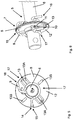
- An agricultural distribution machine has a storage container 1 for storing material to be distributed, preferably seed and / or fertilizer.
- a reservoir 1 is in the Fig. 1 and 2 shown.
- the reservoir is supported on a frame, not shown, of the agricultural distribution machine, wherein the distribution machine is provided for attachment or attachment to an agricultural tractor, not shown.
- the storage container 1 has an outlet region 2. Below the outlet region 2, a plurality of metering elements 3 is arranged transversely to the direction of travel F. The dosing 3 serve to feed the cleanserden seeds in Ausbringierin leading conveyor lines. 4
- a stirring device 5 is arranged above the metering elements 3.
- the stirring device 5 is designed as a rotatably mounted stirring shaft 6.
- the agitator shaft 6 is arranged horizontally transversely to the direction of travel F and extends over the entire width of the reservoir 1.
- the stirring elements 7 consist of a first stirring element component 8 and a second stirring element component 9, as in FIG 4 to 6 shown.
- the first stirring element component 8 has a receiving region 10 for receiving a fastener 11, shown in the Fig. 4 and 6 , Suitable fasteners 11 are for example screws or bolts.
- the first Rlickelementkomponente 8 Due to the releasable attachment of the first Rhakelementkomponente 8 on the agitator 6, the first Rlickelementkomponente 8 can be easily and quickly replaced in case of maintenance and / or wear.
- stirring elements 7 of suitable type and / or in a suitable number can be arranged on the agitator shaft 6.
- stirring elements 7 are set in rotation about the longitudinal axis of the agitator shaft 6 serving as the axis of rotation, transverse to the direction of travel F.
- the stirring elements 7 are used to loosen up the stored in the reservoir 1 seed. This avoids clots and / or blockages and ensures a uniform seed flow to the metering 3.
- the first stirring element 8 is designed like a disk, as it 4 to 6 demonstrate.
- each form elements 13 are arranged in the selected example.
- the mold elements 13 are designed as elevations 13A and recesses 13B.
- the elevations 13A and the recesses 13B face each other in the radial direction.
- the circumferential direction results in an alternating sequence of elevations 13A and recesses 13B.
- the on the different side surfaces of the same disc, ie in the direction of the axis of rotation opposite form elements also alternate, so that each elevation 13A is a recess 13B opposite.
- the agitator shaft 6 is driven in rotation by suitable means and rotates together with the stirring elements 7 attached to it about their longitudinal axis extending transversely to the direction of travel F.
- the mold elements 13 effect in their Passage through the stored seed a seed-loosening stirring action.
- an orientation of the reservoir 1 and / or the stirring shaft 6 parallel to the direction of travel F is possible.
- the number, arrangement and / or shape of the mold elements 13 is not on the in the 4 to 6 limited embodiments shown. In an analogous manner, many embodiments and combinations of elevations 13A and recesses 13B are conceivable.
- the concrete design of the stirring elements 7 depends on the type of material to be applied, since the materials differ in their physical properties, in particular with regard to their fine graininess, flowability and susceptibility to blockages and / or lumps.
- Very fine-grained material such as fine seeds, especially grass seeds, have a strong tendency to form clogs and / or lumps.
- the first stirring element component 8 fastened to the stirring shaft 6 is supplemented by the second stirring element component 9 when using the modular stirring elements 7 according to the invention.
- the first Rhakelementkomponente 8 has a recess 14 into which the second Rlickelementkomponente 9 positively engages, as in the FIGS. 5 and 6 is shown.
- the rotation of the stirring shaft 6 is transferred to the second stirring element component 9 without any loss.
- the second stirring element component 9 is flexible and preferably wire-shaped, shown in FIGS 4 to 6 , and has a closed end 15 and an open end 16.
- materials for the second Rhakelementkomponente 9 are particularly suitable plastic and / or metal.
- the two materials can be used in combination, for example as plastic-coated metal wire.
- the second stirring element component 9 is the stirring shaft 6 formed at least partially encompassing and / or umklammerd. For attachment and / or removal of the second agitator shaft 6, this is bent up by taking advantage of its flexible properties in a suitable degree and attached to the agitator shaft 6 or removed. In cooperation with the flexible embodiment, the second stirring element component 9 is attached to the stirring shaft by means of clamping and / or clamping action. In this case, the shape-retaining restoring force of the second stirring element component 9 acts on the surface of the stirring shaft 6 in the direction of the axis of rotation of the stirring shaft 6.
- the second stirring element component 9 preferably surrounds at least half of the circumference of the agitating shaft 6. The second stirring element component 9 slips along the circumferential direction of the agitating shaft 6 into the recess provided by the positive engagement, in particular of the closed end 15, of the second stirring element component 9 14 prevents the first Rhakelementkomponente 8.
- the stirring shaft 6 encompassing region 17 of the second Rhakelementkomponente 9 is positively against the agitator shaft 6 and at the same time adjacent to the formally fit laterally to the first Rhakelementkomponente 8.
- the second stirring element component 9 is secured against slipping in the longitudinal direction of the stirring shaft 6.
- the agitator shaft 6 is driven to rotate and rotates in the direction of rotation R.
- the open end 16 of the second stirring element component 9 is oriented counter to the direction of rotation. As a result, a retracting effect of the stirring element 7 is prevented. Retraction of limbs, parts of the operator's clothing and / or tools may cause significant injury to the operator or substantial damage to the agitator 5.
- the open end 16 Due to the orientation of the open end 16 opposite to the direction of rotation R, in cooperation with the flexibility of the second stirring element component 9, the open end 16 can, within certain limits, escape an obstacle and move move harmlessly along the obstacle without unfolding a retracting effect.
- the continued rotation in the direction of rotation R causes a pressure of the open end 16 of the second Rhakelementkomponente 9 against the obstacle.
- an obstacle can be given for example by limbs, parts of clothing and / or tools of the operator.
- the increasing pressure against the obstacle causes an increasing acting on the second Rhakelementkomponente 9 and in particular the open end 16 of the second Rlickelementkomponente 9 torque.
- the second stirring element component encompassing the stirring shaft 6 is spread open and / or bent up. This spreading and / or bending of the second stirring element component 9 reduces the clamping action which ensures the attachment of the second stirring element component 9 to the stirring shaft 6.
- the clamping effect is reduced in such a way that the second stirring element component 9 is detached from the agitator shaft 6.
- the limit torque leading to detachment is dependent on the shape-retaining restoring force with which the second stirring element component 9 realizes the fastening clamping action on the agitator shaft 6.
- the limit torque is thus adjustable on the material properties and the geometry of the second Rlickelementkomponente 9 and preferably in such a way that a satisfactory stirring effect is achieved and yet reliable and safe detachment of the second Rlickelementkomponente 9 is ensured by the agitator 6 to injury of a Operator and / or damage to the stirring device 5 to avoid.
- a detached second stirring element component 9 remains in the reservoir 1 and can be recovered by the operator. Due to its flexible properties, the second stirring element component 9 is fully functional even after obstacle-related detachment and thus reusable.
- the detached second stirring element 9 can again in the manner described the stirring shaft 6 and / or the first Rhakelementkomponente 8 are plugged.
- the operator can manually release the second stirring element component 9 from the stirring shaft 6 and / or the first stirring element component 8 in a simple manner. Due to the flexible properties and the attachment by means of clamping action, the second stirring element component 9 can be attached or removed by the operator at any time without tools, comfortably and quickly.
- the described stirring device 5 can be easily adapted to the requirements, in particular to different types of materials to be applied.
- the modular stirring elements 7 represent a particularly economical way to convert an agricultural distributor for different types ofdesignurdem material.
- the attachment and removal of the second stirring element 9 is at any time quickly and conveniently carried out without tools.
- the stirring device 5 according to the invention has a very high level of occupational safety.
- Modular stirring elements 7 and in particular the second stirring element component 9 can also be retrofitted in a simple manner in older distribution machines.
Landscapes
- Life Sciences & Earth Sciences (AREA)
- Soil Sciences (AREA)
- Environmental Sciences (AREA)
- Mixers Of The Rotary Stirring Type (AREA)
Claims (9)
- Distributeur agricole destiné à l'épandage de semence et/ou d'engrais, ledit distributeur comprenant au moins un réservoir (1) destiné à stocker la semence et/ou l'engrais à épandre, au moins une zone de sortie aménagée (2) disposée dans la région inférieure du réservoir (1) et comportant au moins un élément de dosage (3) disposé dans la région de sortie (2) et destiné à introduire la matière à épandre dans des conduits de transport (4) menant à des éléments d'épandage, un agitateur (5) entraîné en rotation étant disposé dans la région inférieure du réservoir (1) au-dessus d'au moins un élément de dosage (3) et l'agitateur (5) étant équipé d'un arbre d'agitation (6) qui est équipé d'au moins un élément d'agitation (7), l'au moins un élément d'agitation (7) étant conçu de manière modulaire à partir d'au moins un premier (8) et un deuxième composant d'élément d'agitation (9), caractérisé en ce que, lorsqu'une valeur limite de couple est atteinte et/ou dépassée, le deuxième composant d'élément d'agitation (9), tournant avec l'arbre d'agitation (6), se déforme par collision avec un obstacle de telle sorte qu'il se détache de l'arbre d'agitation (6) et/ou du premier composant d'élément d'agitation (8) et le deuxième composant d'élément d'agitation (9), détaché de l'arbre d'agitation (6) et/ou du premier composant d'élément d'agitation (8) lorsqu'une valeur limite de couple est atteinte et/ou dépassée, est entièrement fonctionnel et réutilisable.
- Distributeur selon l'une au moins des revendications précédentes, caractérisé en ce que le deuxième composant d'élément d'agitation (9) est flexible.
- Distributeur selon l'une au moins des revendications précédentes, caractérisé en ce que le deuxième composant d'élément d'agitation (9) s'engage au moins partiellement autour de l'arbre d'agitation (6) et l'arbre d'agitation (6) est fixé par pincement à l'arbre d'agitation (6).
- Distributeur selon l'une au moins des revendications précédentes, caractérisé en ce que le premier composant d'élément d'agitation (8) comporte des évidements (14) et le deuxième composant d'élément d'agitation (9) est relié au premier composant d'élément d'agitation (8) par engagement dans les évidements (14) du premier composant d'élément d'agitation (8).
- Distributeur selon l'une au moins des revendications précédentes, caractérisé en ce que le deuxième composant d'élément d'agitation (9) est empêché de coulisser le long de l'axe longitudinal de l'arbre d'agitation (6) par un engagement par complémentarité de formes avec le premier composant d'élément d'agitation (8).
- Distributeur selon l'une au moins des revendications précédentes, caractérisé en ce que le deuxième élément d'agitation (9) s'engage autour de l'arbre d'agitation (6) dans le sens de rotation et comporte une extrémité ouverte (16) qui est orientée dans le sens de la rotation.
- Distributeur selon l'une au moins des revendications précédentes, caractérisé en ce que le deuxième composant d'élément d'agitation (9) est conçu de manière à ne développer aucune action de rétraction lors de la rotation avec l'arbre d'agitation (6).
- Distributeur selon l'une au moins des revendications précédentes, caractérisé en ce que le deuxième composant d'élément d'agitation (9) est en matière synthétique ou en métal.
- Distributeur selon l'une au moins des revendications précédentes, caractérisé en ce que le deuxième composant d'élément d'agitation (9) est conçu sous la forme de fil.
Applications Claiming Priority (1)
| Application Number | Priority Date | Filing Date | Title |
|---|---|---|---|
| DE102016122552.5A DE102016122552A1 (de) | 2016-11-23 | 2016-11-23 | Landwirtschaftliche Verteilmaschine mit Rühreinrichtung |
Publications (2)
| Publication Number | Publication Date |
|---|---|
| EP3326441A1 EP3326441A1 (fr) | 2018-05-30 |
| EP3326441B1 true EP3326441B1 (fr) | 2019-11-06 |
Family
ID=60569856
Family Applications (1)
| Application Number | Title | Priority Date | Filing Date |
|---|---|---|---|
| EP17401114.8A Active EP3326441B1 (fr) | 2016-11-23 | 2017-11-16 | Machine d'épandage agricole dotée d'un dispositif d'agitation |
Country Status (2)
| Country | Link |
|---|---|
| EP (1) | EP3326441B1 (fr) |
| DE (2) | DE202016008713U1 (fr) |
Families Citing this family (2)
| Publication number | Priority date | Publication date | Assignee | Title |
|---|---|---|---|---|
| DE102019118900A1 (de) * | 2019-07-12 | 2021-01-14 | Amazonen-Werke H. Dreyer Gmbh & Co. Kg | Landwirtschaftliche Verteilmaschine mit Rühreinrichtung |
| DE102020003359A1 (de) | 2020-06-03 | 2021-12-09 | Horsch Leeb Application Systems Gmbh | Verteilmaschine, insbesondere pneumatischer Düngerstreuer |
Family Cites Families (5)
| Publication number | Priority date | Publication date | Assignee | Title |
|---|---|---|---|---|
| DE1950873U (de) | 1966-09-30 | 1966-12-01 | Amazonen Werke Dreyer H | Ruehrwelle fuer eine landwirtschaftliche maschine, insbesondere drillmaschine. |
| DE2835011C2 (de) * | 1978-08-10 | 1980-10-02 | Amazonen-Werke H. Dreyer Gmbh & Co Kg, 4507 Hasbergen | Schleuderstreuer, insbesondere für gekörnte Düngemittel |
| US7341009B2 (en) * | 2004-06-25 | 2008-03-11 | Kasco Manufacturing Company, Inc. | Seed hopper |
| FR2883265B1 (fr) * | 2005-03-21 | 2007-05-25 | Sulky Burel Soc Par Actions Si | Dispositif de montage et de reglage d'un doigt d'agitateur facilitant l'ecoulement par une ouverture d'un produit contenu dans une tremie, notamment pour un distributeur d'engrais |
| DE102016113619A1 (de) | 2016-07-25 | 2018-02-08 | Amazonen-Werke H. Dreyer Gmbh & Co. Kg | Landwirtschaftliche Sämaschine mit Rühreinrichtung |
-
2016
- 2016-11-23 DE DE202016008713.5U patent/DE202016008713U1/de active Active
- 2016-11-23 DE DE102016122552.5A patent/DE102016122552A1/de not_active Withdrawn
-
2017
- 2017-11-16 EP EP17401114.8A patent/EP3326441B1/fr active Active
Non-Patent Citations (1)
| Title |
|---|
| None * |
Also Published As
| Publication number | Publication date |
|---|---|
| EP3326441A1 (fr) | 2018-05-30 |
| DE102016122552A1 (de) | 2018-05-24 |
| DE202016008713U1 (de) | 2019-02-25 |
Similar Documents
| Publication | Publication Date | Title |
|---|---|---|
| EP1570716B1 (fr) | Appareil de dosage agricole | |
| EP2832203B1 (fr) | Semoir | |
| EP3275301B1 (fr) | Semoir agricole pourvu d'un dispositif agitateur | |
| EP3326441B1 (fr) | Machine d'épandage agricole dotée d'un dispositif d'agitation | |
| DE202009006698U1 (de) | Walzenförmige Bodenbearbeitungsvorrichtung | |
| DE102011088512B3 (de) | Spreuaufbereitungs- und -verteilvorrichtung | |
| DE1949926C3 (de) | Drillmaschine oder Düngerstreuer mit Dosiervorrichtungen | |
| EP3036982A1 (fr) | Rouleau compacteur | |
| DE102012005112B4 (de) | Abstreifvorrichtung für eine Bodenverdichtungswalze und Bodenverdichtungswalze, insbesondere Grabenwalze | |
| EP3771847B1 (fr) | Attache de courroie et courroie | |
| DE2060413A1 (de) | Erdbewegungsgeraet | |
| DE1189309B (de) | Schlegeltrommel fuer Schlegel-Feldhaecksler | |
| WO1998057530A2 (fr) | Dispositif permettant de combiner la preparation du sol pour les semailles et l'epandage de la semence | |
| DE202021002121U1 (de) | Zinkenbefestigung an einer Aufnahmeeinrichtung | |
| WO2022048708A1 (fr) | Appareil de travail du sol | |
| EP3763187B1 (fr) | Machine d'épandage agricole dotée d'un dispositif d'agitation | |
| DE202008014705U1 (de) | Vorrichtung zum Vorbereiten des Bodens zum Säen und zum Ausbringen von Saatgut | |
| DE8026581U1 (de) | Krümelwalze | |
| EP3278647B1 (fr) | Semoir agricole pourvu d'une roue à semences fendue | |
| EP3228169A1 (fr) | Soc de semoir | |
| EP0439718B1 (fr) | Epandeur centrifuge | |
| DE1905745C3 (de) | Landwirtschaftliches Streugerät für körniges oder pulvriges Streugut | |
| AT43447B (de) | Düngerstreumaschine. | |
| DE202021101470U1 (de) | Landwirtschaftliche Streuvorrichtung | |
| DE4215774A1 (de) | Aufbereitungsmaschine für Halmgut |
Legal Events
| Date | Code | Title | Description |
|---|---|---|---|
| PUAI | Public reference made under article 153(3) epc to a published international application that has entered the european phase |
Free format text: ORIGINAL CODE: 0009012 |
|
| STAA | Information on the status of an ep patent application or granted ep patent |
Free format text: STATUS: THE APPLICATION HAS BEEN PUBLISHED |
|
| AK | Designated contracting states |
Kind code of ref document: A1 Designated state(s): AL AT BE BG CH CY CZ DE DK EE ES FI FR GB GR HR HU IE IS IT LI LT LU LV MC MK MT NL NO PL PT RO RS SE SI SK SM TR |
|
| AX | Request for extension of the european patent |
Extension state: BA ME |
|
| STAA | Information on the status of an ep patent application or granted ep patent |
Free format text: STATUS: REQUEST FOR EXAMINATION WAS MADE |
|
| 17P | Request for examination filed |
Effective date: 20181128 |
|
| RBV | Designated contracting states (corrected) |
Designated state(s): AL AT BE BG CH CY CZ DE DK EE ES FI FR GB GR HR HU IE IS IT LI LT LU LV MC MK MT NL NO PL PT RO RS SE SI SK SM TR |
|
| RIC1 | Information provided on ipc code assigned before grant |
Ipc: A01C 15/00 20060101AFI20190508BHEP Ipc: A01C 7/08 20060101ALN20190508BHEP |
|
| RIC1 | Information provided on ipc code assigned before grant |
Ipc: A01C 7/08 20060101ALN20190515BHEP Ipc: A01C 15/00 20060101AFI20190515BHEP |
|
| GRAP | Despatch of communication of intention to grant a patent |
Free format text: ORIGINAL CODE: EPIDOSNIGR1 |
|
| STAA | Information on the status of an ep patent application or granted ep patent |
Free format text: STATUS: GRANT OF PATENT IS INTENDED |
|
| INTG | Intention to grant announced |
Effective date: 20190627 |
|
| GRAS | Grant fee paid |
Free format text: ORIGINAL CODE: EPIDOSNIGR3 |
|
| GRAA | (expected) grant |
Free format text: ORIGINAL CODE: 0009210 |
|
| STAA | Information on the status of an ep patent application or granted ep patent |
Free format text: STATUS: THE PATENT HAS BEEN GRANTED |
|
| AK | Designated contracting states |
Kind code of ref document: B1 Designated state(s): AL AT BE BG CH CY CZ DE DK EE ES FI FR GB GR HR HU IE IS IT LI LT LU LV MC MK MT NL NO PL PT RO RS SE SI SK SM TR |
|
| REG | Reference to a national code |
Ref country code: GB Ref legal event code: FG4D Free format text: NOT ENGLISH |
|
| REG | Reference to a national code |
Ref country code: CH Ref legal event code: EP Ref country code: AT Ref legal event code: REF Ref document number: 1197520 Country of ref document: AT Kind code of ref document: T Effective date: 20191115 |
|
| REG | Reference to a national code |
Ref country code: IE Ref legal event code: FG4D Free format text: LANGUAGE OF EP DOCUMENT: GERMAN |
|
| REG | Reference to a national code |
Ref country code: DE Ref legal event code: R096 Ref document number: 502017002803 Country of ref document: DE |
|
| REG | Reference to a national code |
Ref country code: NL Ref legal event code: MP Effective date: 20191106 |
|
| REG | Reference to a national code |
Ref country code: LT Ref legal event code: MG4D |
|
| PG25 | Lapsed in a contracting state [announced via postgrant information from national office to epo] |
Ref country code: PT Free format text: LAPSE BECAUSE OF FAILURE TO SUBMIT A TRANSLATION OF THE DESCRIPTION OR TO PAY THE FEE WITHIN THE PRESCRIBED TIME-LIMIT Effective date: 20200306 Ref country code: SE Free format text: LAPSE BECAUSE OF FAILURE TO SUBMIT A TRANSLATION OF THE DESCRIPTION OR TO PAY THE FEE WITHIN THE PRESCRIBED TIME-LIMIT Effective date: 20191106 Ref country code: LV Free format text: LAPSE BECAUSE OF FAILURE TO SUBMIT A TRANSLATION OF THE DESCRIPTION OR TO PAY THE FEE WITHIN THE PRESCRIBED TIME-LIMIT Effective date: 20191106 Ref country code: FI Free format text: LAPSE BECAUSE OF FAILURE TO SUBMIT A TRANSLATION OF THE DESCRIPTION OR TO PAY THE FEE WITHIN THE PRESCRIBED TIME-LIMIT Effective date: 20191106 Ref country code: NO Free format text: LAPSE BECAUSE OF FAILURE TO SUBMIT A TRANSLATION OF THE DESCRIPTION OR TO PAY THE FEE WITHIN THE PRESCRIBED TIME-LIMIT Effective date: 20200206 Ref country code: GR Free format text: LAPSE BECAUSE OF FAILURE TO SUBMIT A TRANSLATION OF THE DESCRIPTION OR TO PAY THE FEE WITHIN THE PRESCRIBED TIME-LIMIT Effective date: 20200207 Ref country code: BG Free format text: LAPSE BECAUSE OF FAILURE TO SUBMIT A TRANSLATION OF THE DESCRIPTION OR TO PAY THE FEE WITHIN THE PRESCRIBED TIME-LIMIT Effective date: 20200206 Ref country code: LT Free format text: LAPSE BECAUSE OF FAILURE TO SUBMIT A TRANSLATION OF THE DESCRIPTION OR TO PAY THE FEE WITHIN THE PRESCRIBED TIME-LIMIT Effective date: 20191106 Ref country code: PL Free format text: LAPSE BECAUSE OF FAILURE TO SUBMIT A TRANSLATION OF THE DESCRIPTION OR TO PAY THE FEE WITHIN THE PRESCRIBED TIME-LIMIT Effective date: 20191106 Ref country code: NL Free format text: LAPSE BECAUSE OF FAILURE TO SUBMIT A TRANSLATION OF THE DESCRIPTION OR TO PAY THE FEE WITHIN THE PRESCRIBED TIME-LIMIT Effective date: 20191106 |
|
| PG25 | Lapsed in a contracting state [announced via postgrant information from national office to epo] |
Ref country code: HR Free format text: LAPSE BECAUSE OF FAILURE TO SUBMIT A TRANSLATION OF THE DESCRIPTION OR TO PAY THE FEE WITHIN THE PRESCRIBED TIME-LIMIT Effective date: 20191106 Ref country code: IS Free format text: LAPSE BECAUSE OF FAILURE TO SUBMIT A TRANSLATION OF THE DESCRIPTION OR TO PAY THE FEE WITHIN THE PRESCRIBED TIME-LIMIT Effective date: 20200306 Ref country code: RS Free format text: LAPSE BECAUSE OF FAILURE TO SUBMIT A TRANSLATION OF THE DESCRIPTION OR TO PAY THE FEE WITHIN THE PRESCRIBED TIME-LIMIT Effective date: 20191106 |
|
| PG25 | Lapsed in a contracting state [announced via postgrant information from national office to epo] |
Ref country code: AL Free format text: LAPSE BECAUSE OF FAILURE TO SUBMIT A TRANSLATION OF THE DESCRIPTION OR TO PAY THE FEE WITHIN THE PRESCRIBED TIME-LIMIT Effective date: 20191106 |
|
| PG25 | Lapsed in a contracting state [announced via postgrant information from national office to epo] |
Ref country code: DK Free format text: LAPSE BECAUSE OF FAILURE TO SUBMIT A TRANSLATION OF THE DESCRIPTION OR TO PAY THE FEE WITHIN THE PRESCRIBED TIME-LIMIT Effective date: 20191106 Ref country code: CZ Free format text: LAPSE BECAUSE OF FAILURE TO SUBMIT A TRANSLATION OF THE DESCRIPTION OR TO PAY THE FEE WITHIN THE PRESCRIBED TIME-LIMIT Effective date: 20191106 Ref country code: RO Free format text: LAPSE BECAUSE OF FAILURE TO SUBMIT A TRANSLATION OF THE DESCRIPTION OR TO PAY THE FEE WITHIN THE PRESCRIBED TIME-LIMIT Effective date: 20191106 Ref country code: EE Free format text: LAPSE BECAUSE OF FAILURE TO SUBMIT A TRANSLATION OF THE DESCRIPTION OR TO PAY THE FEE WITHIN THE PRESCRIBED TIME-LIMIT Effective date: 20191106 Ref country code: LU Free format text: LAPSE BECAUSE OF NON-PAYMENT OF DUE FEES Effective date: 20191116 Ref country code: ES Free format text: LAPSE BECAUSE OF FAILURE TO SUBMIT A TRANSLATION OF THE DESCRIPTION OR TO PAY THE FEE WITHIN THE PRESCRIBED TIME-LIMIT Effective date: 20191106 |
|
| REG | Reference to a national code |
Ref country code: DE Ref legal event code: R097 Ref document number: 502017002803 Country of ref document: DE |
|
| REG | Reference to a national code |
Ref country code: BE Ref legal event code: MM Effective date: 20191130 |
|
| PG25 | Lapsed in a contracting state [announced via postgrant information from national office to epo] |
Ref country code: SM Free format text: LAPSE BECAUSE OF FAILURE TO SUBMIT A TRANSLATION OF THE DESCRIPTION OR TO PAY THE FEE WITHIN THE PRESCRIBED TIME-LIMIT Effective date: 20191106 Ref country code: SK Free format text: LAPSE BECAUSE OF FAILURE TO SUBMIT A TRANSLATION OF THE DESCRIPTION OR TO PAY THE FEE WITHIN THE PRESCRIBED TIME-LIMIT Effective date: 20191106 Ref country code: MC Free format text: LAPSE BECAUSE OF FAILURE TO SUBMIT A TRANSLATION OF THE DESCRIPTION OR TO PAY THE FEE WITHIN THE PRESCRIBED TIME-LIMIT Effective date: 20191106 |
|
| PLBE | No opposition filed within time limit |
Free format text: ORIGINAL CODE: 0009261 |
|
| STAA | Information on the status of an ep patent application or granted ep patent |
Free format text: STATUS: NO OPPOSITION FILED WITHIN TIME LIMIT |
|
| 26N | No opposition filed |
Effective date: 20200807 |
|
| PG25 | Lapsed in a contracting state [announced via postgrant information from national office to epo] |
Ref country code: IE Free format text: LAPSE BECAUSE OF NON-PAYMENT OF DUE FEES Effective date: 20191116 |
|
| PG25 | Lapsed in a contracting state [announced via postgrant information from national office to epo] |
Ref country code: BE Free format text: LAPSE BECAUSE OF NON-PAYMENT OF DUE FEES Effective date: 20191130 Ref country code: SI Free format text: LAPSE BECAUSE OF FAILURE TO SUBMIT A TRANSLATION OF THE DESCRIPTION OR TO PAY THE FEE WITHIN THE PRESCRIBED TIME-LIMIT Effective date: 20191106 |
|
| PG25 | Lapsed in a contracting state [announced via postgrant information from national office to epo] |
Ref country code: IT Free format text: LAPSE BECAUSE OF FAILURE TO SUBMIT A TRANSLATION OF THE DESCRIPTION OR TO PAY THE FEE WITHIN THE PRESCRIBED TIME-LIMIT Effective date: 20191106 |
|
| REG | Reference to a national code |
Ref country code: DE Ref legal event code: R081 Ref document number: 502017002803 Country of ref document: DE Owner name: AMAZONEN-WERKE H. DREYER SE & CO. KG, DE Free format text: FORMER OWNER: AMAZONEN-WERKE H. DREYER GMBH & CO. KG, 49205 HASBERGEN, DE |
|
| PG25 | Lapsed in a contracting state [announced via postgrant information from national office to epo] |
Ref country code: CY Free format text: LAPSE BECAUSE OF FAILURE TO SUBMIT A TRANSLATION OF THE DESCRIPTION OR TO PAY THE FEE WITHIN THE PRESCRIBED TIME-LIMIT Effective date: 20191106 |
|
| REG | Reference to a national code |
Ref country code: CH Ref legal event code: PL |
|
| PG25 | Lapsed in a contracting state [announced via postgrant information from national office to epo] |
Ref country code: HU Free format text: LAPSE BECAUSE OF FAILURE TO SUBMIT A TRANSLATION OF THE DESCRIPTION OR TO PAY THE FEE WITHIN THE PRESCRIBED TIME-LIMIT; INVALID AB INITIO Effective date: 20171116 Ref country code: MT Free format text: LAPSE BECAUSE OF FAILURE TO SUBMIT A TRANSLATION OF THE DESCRIPTION OR TO PAY THE FEE WITHIN THE PRESCRIBED TIME-LIMIT Effective date: 20191106 |
|
| PG25 | Lapsed in a contracting state [announced via postgrant information from national office to epo] |
Ref country code: LI Free format text: LAPSE BECAUSE OF NON-PAYMENT OF DUE FEES Effective date: 20201130 Ref country code: CH Free format text: LAPSE BECAUSE OF NON-PAYMENT OF DUE FEES Effective date: 20201130 |
|
| PGFP | Annual fee paid to national office [announced via postgrant information from national office to epo] |
Ref country code: FR Payment date: 20210930 Year of fee payment: 5 |
|
| PG25 | Lapsed in a contracting state [announced via postgrant information from national office to epo] |
Ref country code: TR Free format text: LAPSE BECAUSE OF FAILURE TO SUBMIT A TRANSLATION OF THE DESCRIPTION OR TO PAY THE FEE WITHIN THE PRESCRIBED TIME-LIMIT Effective date: 20191106 |
|
| PG25 | Lapsed in a contracting state [announced via postgrant information from national office to epo] |
Ref country code: MK Free format text: LAPSE BECAUSE OF FAILURE TO SUBMIT A TRANSLATION OF THE DESCRIPTION OR TO PAY THE FEE WITHIN THE PRESCRIBED TIME-LIMIT Effective date: 20191106 |
|
| GBPC | Gb: european patent ceased through non-payment of renewal fee |
Effective date: 20211116 |
|
| PG25 | Lapsed in a contracting state [announced via postgrant information from national office to epo] |
Ref country code: GB Free format text: LAPSE BECAUSE OF NON-PAYMENT OF DUE FEES Effective date: 20211116 |
|
| P01 | Opt-out of the competence of the unified patent court (upc) registered |
Effective date: 20230523 |
|
| PG25 | Lapsed in a contracting state [announced via postgrant information from national office to epo] |
Ref country code: FR Free format text: LAPSE BECAUSE OF NON-PAYMENT OF DUE FEES Effective date: 20221130 |
|
| REG | Reference to a national code |
Ref country code: AT Ref legal event code: MM01 Ref document number: 1197520 Country of ref document: AT Kind code of ref document: T Effective date: 20221116 |
|
| PG25 | Lapsed in a contracting state [announced via postgrant information from national office to epo] |
Ref country code: AT Free format text: LAPSE BECAUSE OF NON-PAYMENT OF DUE FEES Effective date: 20221116 |
|
| PGFP | Annual fee paid to national office [announced via postgrant information from national office to epo] |
Ref country code: DE Payment date: 20230919 Year of fee payment: 7 |