EP3325915B1 - Optische hochgeschwindigkeitskohärenztomografie mit mehreren interferometern mit unterdrücktem mehrfachstreuungsübersprechen - Google Patents
Optische hochgeschwindigkeitskohärenztomografie mit mehreren interferometern mit unterdrücktem mehrfachstreuungsübersprechen Download PDFInfo
- Publication number
- EP3325915B1 EP3325915B1 EP16741928.2A EP16741928A EP3325915B1 EP 3325915 B1 EP3325915 B1 EP 3325915B1 EP 16741928 A EP16741928 A EP 16741928A EP 3325915 B1 EP3325915 B1 EP 3325915B1
- Authority
- EP
- European Patent Office
- Prior art keywords
- radiation
- delayed
- interferometer
- time delay
- delay
- Prior art date
- Legal status (The legal status is an assumption and is not a legal conclusion. Google has not performed a legal analysis and makes no representation as to the accuracy of the status listed.)
- Active
Links
Images




Classifications
-
- G—PHYSICS
- G01—MEASURING; TESTING
- G01B—MEASURING LENGTH, THICKNESS OR SIMILAR LINEAR DIMENSIONS; MEASURING ANGLES; MEASURING AREAS; MEASURING IRREGULARITIES OF SURFACES OR CONTOURS
- G01B9/00—Measuring instruments characterised by the use of optical techniques
- G01B9/02—Interferometers
- G01B9/02055—Reduction or prevention of errors; Testing; Calibration
- G01B9/0207—Error reduction by correction of the measurement signal based on independently determined error sources, e.g. using a reference interferometer
-
- A—HUMAN NECESSITIES
- A61—MEDICAL OR VETERINARY SCIENCE; HYGIENE
- A61B—DIAGNOSIS; SURGERY; IDENTIFICATION
- A61B5/00—Measuring for diagnostic purposes; Identification of persons
- A61B5/0059—Measuring for diagnostic purposes; Identification of persons using light, e.g. diagnosis by transillumination, diascopy, fluorescence
- A61B5/0062—Arrangements for scanning
- A61B5/0066—Optical coherence imaging
-
- G—PHYSICS
- G01—MEASURING; TESTING
- G01B—MEASURING LENGTH, THICKNESS OR SIMILAR LINEAR DIMENSIONS; MEASURING ANGLES; MEASURING AREAS; MEASURING IRREGULARITIES OF SURFACES OR CONTOURS
- G01B9/00—Measuring instruments characterised by the use of optical techniques
- G01B9/02—Interferometers
- G01B9/02015—Interferometers characterised by the beam path configuration
- G01B9/02027—Two or more interferometric channels or interferometers
-
- G—PHYSICS
- G01—MEASURING; TESTING
- G01B—MEASURING LENGTH, THICKNESS OR SIMILAR LINEAR DIMENSIONS; MEASURING ANGLES; MEASURING AREAS; MEASURING IRREGULARITIES OF SURFACES OR CONTOURS
- G01B9/00—Measuring instruments characterised by the use of optical techniques
- G01B9/02—Interferometers
- G01B9/02055—Reduction or prevention of errors; Testing; Calibration
- G01B9/02056—Passive reduction of errors
-
- G—PHYSICS
- G01—MEASURING; TESTING
- G01B—MEASURING LENGTH, THICKNESS OR SIMILAR LINEAR DIMENSIONS; MEASURING ANGLES; MEASURING AREAS; MEASURING IRREGULARITIES OF SURFACES OR CONTOURS
- G01B9/00—Measuring instruments characterised by the use of optical techniques
- G01B9/02—Interferometers
- G01B9/02055—Reduction or prevention of errors; Testing; Calibration
- G01B9/02075—Reduction or prevention of errors; Testing; Calibration of particular errors
-
- G—PHYSICS
- G01—MEASURING; TESTING
- G01B—MEASURING LENGTH, THICKNESS OR SIMILAR LINEAR DIMENSIONS; MEASURING ANGLES; MEASURING AREAS; MEASURING IRREGULARITIES OF SURFACES OR CONTOURS
- G01B9/00—Measuring instruments characterised by the use of optical techniques
- G01B9/02—Interferometers
- G01B9/0209—Low-coherence interferometers
- G01B9/02091—Tomographic interferometers, e.g. based on optical coherence
-
- A—HUMAN NECESSITIES
- A61—MEDICAL OR VETERINARY SCIENCE; HYGIENE
- A61B—DIAGNOSIS; SURGERY; IDENTIFICATION
- A61B3/00—Apparatus for testing the eyes; Instruments for examining the eyes
- A61B3/10—Objective types, i.e. instruments for examining the eyes independent of the patients' perceptions or reactions
- A61B3/102—Objective types, i.e. instruments for examining the eyes independent of the patients' perceptions or reactions for optical coherence tomography [OCT]
-
- A—HUMAN NECESSITIES
- A61—MEDICAL OR VETERINARY SCIENCE; HYGIENE
- A61B—DIAGNOSIS; SURGERY; IDENTIFICATION
- A61B5/00—Measuring for diagnostic purposes; Identification of persons
- A61B5/72—Signal processing specially adapted for physiological signals or for diagnostic purposes
- A61B5/7203—Signal processing specially adapted for physiological signals or for diagnostic purposes for noise prevention, reduction or removal
- A61B5/7207—Signal processing specially adapted for physiological signals or for diagnostic purposes for noise prevention, reduction or removal of noise induced by motion artifacts
Definitions
- Embodiments of the invention relate to the field of optical coherence tomography. Background
- OCT Optical Coherence Tomography
- Axial information is obtained in OCT through interferometric methods.
- One approach to generate images (2D) and volume representations (3D) of the histology of tissue is to move the beam laterally over the area of interest. This movement has been traditionally done by means of mechanical displacement of some optical element within the system, such as the waveguide in the case of fiber-based systems. Alternatively, the sample can be moved underneath a stationary beam. The most common solution utilizes a moving mirror in the beam path in the sample arm of the interferometer. Although this method is effective, it has drawbacks, especially in terms of reliability, manufacturing cost, maintenance cost, complexity of adjustment, final system size, etc.
- MOEMS technology Micro-opto-electromechanical systems
- MOEMS Micro-opto-electromechanical systems
- these devices suffer from many of the same problems as their macroscopic versions and they pose their own challenges in terms of encapsulation, sterilization, etc.
- High-speed Optical Coherence Tomography (OCT) imaging is important for 3D scans of large tissue volumes, for the evaluation of fast dynamics in the sample and in indications prone to motion artifacts because of mechanical instability or body movements. Meeting this goal may require a significant increase in actual acquisition speed beyond the line speed of a single axial scanner (which is fixed by the physical properties of the external cavity or delay line) to obtain a sufficiently high sampling rate. Also, it may require improving the signal-to-noise (SNR) of the system to ensure good image quality in spite of high speeds.
- SNR signal-to-noise
- Full-field OCT systems may meet these goals a priori because of their construction. However, they may suffer from cross-talk between adjacent channels and image quality problems.
- Full-field OCT (FF-OCT) systems also require 2D imaging sensors, which may limit them practically to wavelengths where such sensors are affordable and have sufficient resolutions (currently only ⁇ 1 ⁇ m). Such sensors also limit image acquisition speed to the frame rate of the imager.
- Line-scan OCT limits the parallel acquisition to a single line and uses a scanning element to gain additional directions.
- a solution described in WIPO Patent Application Publication WO 2014/089504 uses a spatially expanded source that is conformed into a plurality of separate beams by means of a mechanically actuated mask. The beams are then scanned over the surface of the tissue to be analyzed in order to produce the images. As long as the separation of these beams is large (the sampling is sparse), cross-talk can be effectively reduced.
- the problems with this approach are the loss in optical throughput when the source is masked, the need for a 2D imager (especially at longer wavelengths), and the trade-off between dense sampling and cross-talk.
- the invention provides a time-domain optical coherence tomography system according to claim 1, and a method of performing time-domain optical coherence tomography according to claim 11.
- Advantageous embodiments thereof are set out in the dependent claims.
- references in the specification to "one embodiment,” “an embodiment,” “an example embodiment,” etc. indicate that the embodiment described may include a particular feature, structure, or characteristic, but every embodiment may not necessarily include the particular feature, structure, or characteristic. Moreover, such phrases do not necessarily refer to the same embodiment. Further, when a particular feature, structure or characteristic is described in connection with an embodiment, it would be within the knowledge of one skilled in the art to effect such feature, structure or characteristic in connection with other embodiments whether or not explicitly described.
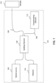
- FIG. 1 illustrates an OCT system 101, according to a non-claimed example.
- OCT system 101 includes a compensating element 112, and is used for imaging a sample 110.
- Compensating element 112 may be a variable delay system.
- compensating element 112 may be used to provide a variable delay to the light within OCT system 101, while compensating for the effects of birefringence.
- the use of the term "light” may refer to any range of the electromagnetic spectrum.
- An example wavelength of light that may be used is infrared radiation at a wavelength of around 1.3 ⁇ m.
- OCT system 101 further includes an optical source 102, a mixing splitter 104, a sample arm 106, a reference arm 108, and a detector 114.
- detector 114 is a balanced detector pair.
- compensating element 112 is located within reference arm 108. However, it should be understood that compensating element 112 may also be located in sample arm 106. Alternatively, various components of compensating element 112 may be present in both sample arm 106 and reference arm 108. For example, components of compensating element 112 that introduce a variable delay to the light may be located in sample arm 106, while components that modulate different polarization modes of the light to reduce birefringence may be located in reference arm 108.
- sample arm 106 and reference arm 108 are optical waveguides, such as patterned waveguides or optical fibers.
- all of the components of OCT system 101 are integrated onto a planar lightwave circuit (PLC). In another embodiment, at least all the components within compensating element 112 are integrated on the same substrate of a PLC. Other implementations may be considered as well, such as, for example, fiber optic systems, free-space optical systems, photonic crystal systems, etc.
- OCT system 101 may include any number of other optical elements not shown for the sake of clarity.
- OCT system 101 may include mirrors, lenses, gratings, splitters, micromechanical elements, etc., along the paths of sample arm 106 or reference arm 108.
- Mixing splitter 104 is used to direct light received from optical source 102 to both sample arm 106 and reference arm 108.
- Mixing splitter 104 may be, for example, a bi-directional coupler, an optical splitter, or any other modulating optical device that converts a single beam of light into two or more beams of light.
- Sample 110 may be any suitable sample to be imaged, such as tissue.
- the light scans at a certain depth within sample 110 and the scattered radiation is collected back into sample arm 106.
- the scattered radiation is collected back into a different waveguide than the transmitting waveguide. The scan depth may be chosen via the delay imposed on the light within compensating element 112.
- Light within sample arm 106 and reference arm 108 is recombined before being received at detector 114.
- the light is recombined by mixing splitter 104.
- the light is recombined at a different optical coupling element than mixing splitter 104.
- compensating element 112 is used to describe the components that introduce variable delay as well as reduce birefringence.
- compensating element 112 one may categorize the set of components related to introducing variable delay as a variable delay unit and the set of components related to reducing birefringence as an optical modulating unit.
- FIG. 6 shows an example optical system 600 for focusing light from two output apertures 602 and 604 on tissue 606.
- Figure 6 illustrates the multiple scattering effect, where a multiply scattered photon 608 (in a quasi-diffusive regime) coming from the excitation in a Beam 1 channel is collected by a Beam 2 channel and may contribute to the interference signal for Beam 2 channel.
- Imaging depth may be defined as the depth in the tissue where the contribution of single and multiple scattered photons to the OCT signal is equal.
- FIG. 7 illustrates this concept. As shown in FIG. 7 , ignoring focus effects, the maximum potential imaging depth z 2 goes down to zi when multiple scattering cross-talk between apertures takes place.
- FIG. 8 This multiple scattering cross-talk effect is further illustrated in FIG. 8 .
- diffusive or quasi-diffusive photon propagation from two lateral beams 804 contribute to the collected power in a middle beam 808.
- Constant fluence lines 802 correspond to the diffusive or quasi-diffusive fields generated by two independent excitation apertures.
- constant fluence lines 802 are overlaid on a representation of the corresponding excitation beams 804 and collection middle beam 808. The addition of multiple scattering contributions from excitation sources that are non-confocal with collection at distances shorter than the diffusion length for photon transport further reduce imaging depth and contrast.
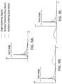
- FIGS. 9A, 9B, and 9C show the effect of the different multiple scattering contributions on the interference signal generated by a differential reflector at a fixed depth in tissue.
- the information-carrying single-scattering component has a width that is related to the coherence length of the source in a dispersion-adjusted OCT system.
- FIG. 9A shows an example intensity of photon propagation before adding a delay to shift the background interference due to multiple scattering out of coherence.
- FIG. 9B shows an example intensity of photon propagation after introducing a delay in an adjacent channel.
- FIG. 9C shows example reciprocal behavior of intensity of photon propagation in the delayed adjacent channel with respect to the excitation in the collection channel shown in FIG. 9B .
- the small-angle multiple scattering caused by excitation with the same aperture as used for collection cannot be decoupled from the single-scattering contribution, and adds a tail to the collected signal that degrades contrast and ultimately limits system imaging depth.
- the multiple scattering contributions from adjacent apertures that are non-confocal with a collection aperture add a background interference with a larger path-length dispersion. Further discussion of such scattering may be found in B. Karamata, "Multiple Scattering in Wide-Field Optical Coherence Tomography," Thesis EPFL (2004 ).
- Some embodiments herein unlink image speed enhancement from image degradation due to the cross-talk caused by multiple scattering. By suppressing this cross-talk, which may be caused by the presence of multiple scattering, embodiments keep the advantages of increased speed and potential SNR and regain optimum image quality.
- multiple interferometers may multiply the effective line rate by the number of replicated interferometers.
- cross-talk between channels is suppressed by means of multiplexing, such as frequency multiplexing or time multiplexing between channels.
- the invention provides shifting adjacent interferometer signals out of coherence with respect to each other, such that any significant multiple scattering contributions from beams/apertures are out of coherence with respect to each other.
- time delays provide such shifting.
- the appropriate time delays may be determined by taking into account the non-symmetrical property of multiple scattering caused by excitation by the beam from the same aperture that is also used for collection. These relative time delays may depend on the geometrical configuration of the different beams and on sample properties, and can be determined experimentally or through simulation tools (like Monte Carlo methods).
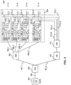
- FIG. 2 illustrates a block diagram of a multi-interferometer Swept Source OCT system 200, according to a non-claimed example.
- OCT system 200 includes a variable wavelength optical source 202, a splitter 206, and interferometers 208.
- a path 204 connects variable wavelength source 202 to splitter 206.
- Beam path 204 may be a waveguide, according to an embodiment.
- Splitter 206 may split beam of radiation generated by variable wavelength source 202 into multiple beams over paths 207_1, 207_2, 207_3, ..., 207_N.
- Splitting element 206 may be, for example, a bi-directional coupler, an optical splitter, or any other optical device that converts a single beam of light into two or more beams of light.
- each output of splitter 206 is received by an interferometer of interferometers 208.
- Each output of splitter 206 may have the same functionality as an optical source, for example optical source 102, for its corresponding interferometer.
- a first output of splitter 206, on path 207_1 is received by interferometer 208_1.
- a second output of splitter 206, on path 207_2, is received by interferometer 208_2.
- a third output of splitter 206, on path 207_3, is received by interferometer 208_3.
- An N th output of splitter 206, on path 207_N is received by interferometer 208_N, wherein N is an integer.
- each output beam of splitter 206 is delayed using a delay element.
- the beam over path 207_1 may be delayed by time delay ⁇ 1 using delay element 210_1
- the beam over path 207_2 may be delayed by time delay ⁇ 2 using delay element 210_2
- the beam over path 207_3 may be delayed by time delay ⁇ 3 using delay element 210_3
- the beam over path 207_N may be delayed by time delay ⁇ N using delay element 210_N.
- delay elements 210_1, 210_2, 210_3, and 210 N may be implemented as part of their corresponding interferometers. In another embodiment, delay elements 210_1, 210_2, 210_3, and 210_N may be implemented on their respective beam paths outside their corresponding interferometers.
- the example embodiment of FIG. 1 may be incorporated into a multiple-interferometer 208 construction for SS-OCT with separation of beams on paths 207_1, 207_2, 207_3, ..., 207_N by means of coherence shifting created by different delays ⁇ 1 , ⁇ 2 , ⁇ 3 , ..., ⁇ N , respectively.
- the time differences between the optical signals delayed according to delays ⁇ 1 , ⁇ 2 , ⁇ 3 , ..., ⁇ N may be larger than the coherence time of the source increased by a factor of the reduced mean free path of light in a tissue undergoing tomography at the working wavelength, depending on the conditions of multiple scattering.
- differences between any pair of delays ⁇ 1 , ⁇ 2 , ⁇ 3 , ..., ⁇ N are large enough to shift adjacent interferometer signals out of coherence with respect to each other, as described above.
- time delay ⁇ i may be determined by taking into account the non-symmetrical shape of multiple scattering caused by and detected by interferometer 208_i.
- the difference between a first time delay applied to a first beam and a second time delay applied to a second beam may be greater than a coherence time of the first and second beams.
- outputs 207 of splitter 206 after being delayed by delay elements 210, are fed to mixing splitters 216 in each respective interferometer.
- Mixing splitter 216 then generate sample signals on sample arms 212, and reference signals on reference arms 214.
- mixing splitter 216_1 generates a sample signal on arm 212_1 of interferometer 208_1, and a reference signal on arm 214_1 of interferometer 208_1.
- the reference signal, and sample signal after being scattered by a tissue undergoing tomography, are fed to mixing splitters 218 that are connected to detecting elements 220 in each interferometer.
- Detecting elements 220 each may include two detectors in a balanced configuration.
- the lengths of each individual sample and reference arm pair may determine actual interference within each channel.
- the length of the arms may be equal for all replicas and can be tuned to maximize image quality. Delay elements on the sample and reference arms may be used for tuning.
- FIG. 3 illustrates a block diagram of a Time Domain OCT system 300, according to an embodiment of the invention.
- OCT system 300 may include a source 302, a first splitter 306, a second splitter 308, a variable delay element 310, a third splitter 312, and interferometers 314.
- Source 302 generates a beam of radiation.
- source 302 is a superluminescent diode (SLED).
- a path 304 may connect source 302 to splitter 306.
- Beam path 304 may be a waveguide, according to an embodiment.
- Splitter 306 may split the beam of radiation generated by source 302 into two beams over paths 307_1 and 307_2.
- Splitting element 306 may be, for example, a bi-directional coupler, an optical splitter, or any other modulating optical device that converts a single beam of light into two or more beams of light.
- the output of splitter 306 over path 307_1 is received by splitter 308, and the output of splitter 306 over path 307_2 is received by variable delay element 310.
- the beam on path 307_1 is used to generate a sample beam for interferometry and the beam on path 307_2 is used to generate a reference beam for interferometry.
- Splitting the sample and reference signal in this manner may prevent the need for a delay line in each individual interferometer.
- variable delay element 310 provides a common variable delay to the beam on path 307_2.
- Variable delay element 310 may provide group delay modulation.
- the output of variable delay element 310 may be split, using splitter 312, into output beams on output paths 313.
- Splitting element 312 may be, for example, a bi-directional coupler, an optical splitter, or any other modulating optical device that converts a single beam of light into two or more beams of light.
- Each beam on paths 313 may be received by respective interferometers 314.
- a first output of splitter 312, on path 313_1 may be received by interferometer 314_1.
- a second output of splitter 312, on path 313_2, may be received by interferometer 314_2.
- a third output of splitter 312, on path 313_3, may be received by interferometer 314_3.
- An N th output of splitter 312, on path 313_N may be received by interferometer 314_N, where N is an integer.
- splitter 308 splits the beam on path 307_1 into output beams on paths 309.
- Each beam on paths 309 may be received by respective interferometers 314.
- a first output of splitter 308, on path 309_1 may be received by interferometer 314_1.
- a second output of splitter 308, on path 309_2 may be received by interferometer 314_2.
- a third output of splitter 308, on path 309_3, may be received by interferometer 314_3.
- An N th output of splitter 308, on path 309_N may be received by interferometer 314_N, where N is an integer.
- each output beam of splitter 312 is delayed using a delay element.
- the beam over path 313_1 may be delayed by time delay ⁇ 1 using delay element 318_1
- the beam over path 313_2 may be delayed by time delay ⁇ 2 using delay element 318_2
- the beam over path 313_3 may be delayed by time delay ⁇ 3 using delay element 318_3
- the beam over path 313_N may be delayed by time delay ⁇ N using delay element 318_N.
- each output beam of splitter 308 is delayed using a delay element 320.
- the beam over path 309_1 may be delayed by time delay ⁇ 1 using delay element 320_1
- the beam over path 309_2 may be delayed by time delay ⁇ 2 using delay element 320_2
- the beam over path 309_3 may be delayed by time delay ⁇ 3 using delay element 320_3
- the beam over path 309_N may be delayed by time delay ⁇ N using delay element 320_N.
- the same delays may be applied to beams on paths 309 and the beam on a path 313 corresponding to a same interferometer.
- the delay introduced by delay element 318_1 on a beam on path 313_1 may be the same as the delay introduced by delay element 320_1 on a beam on path 309_1.
- differences between any pair of delays ⁇ 1 , ⁇ 2 , ⁇ 3 , ..., ⁇ N are large enough so as to preclude any significant cross-talk between channels.
- the time differences between the optical signals delayed according to delays ⁇ 1 , ⁇ 2 , ⁇ 3 , ..., ⁇ N may be larger than the coherence time of the source increased by a factor of the reduced mean free path of light in a tissue undergoing tomography at the working wavelength, depending on the conditions of multiple scattering.
- differences between any pair of delays ⁇ 1 , ⁇ 2 , ⁇ 3 , ..., ⁇ N are large enough to shift adjacent interferometer signals out of coherence with respect to each other, as described above.
- time delay ⁇ i is determined by taking into account the non-symmetrical shape of multiple scattering caused by and detected by interferometer 208_i.
- the difference between a first time delay applied to a first beam and a second time delay applied to a second beam may be greater than a coherence time of the first and second beams.
- delay elements 318 and 320 may be implemented as part of their corresponding interferometers. In another embodiment, delay elements 318 and 320 may be implemented on their respective beam paths outside their corresponding interferometers.
- beams on each path 309 after being delayed by delaying elements 320, are fed to respective output mixing splitters 322.
- Mixing splitters 322 send the light to the sample and direct reflections coming back from the sample to a first input of respective mixing splitters 324.
- the beam on path 309_1 after being delayed by delaying element 320_1, is fed to output mixing splitters 322_1 to generate a sample light from interferometer 314_1. The reflection of the sample light is then fed to a first input of mixing splitter 324_1.
- Matched reference lines 313, after being delayed by delaying elements 318, are fed to respective second inputs of mixing splitters 324, whose outputs are in turn connected to respective detecting elements 326 in each interferometer 314.
- Detecting elements 326 each may include two detectors in a balanced configuration. For example, the beam on path 313_1, after being delayed by delaying element 318_1, is fed to a second input of mixing splitter 324_1 whose outputs are in turn connected to detecting elements 326_1.
- source 302 power may be amplified through an optical amplifier (e.g. an SOA or a doped fiber amplifier) so as to profit from the extended maximum allowable power manageable by the combination of interferometers.
- an optical amplifier e.g. an SOA or a doped fiber amplifier
- FIG. 4 illustrates a flowchart of an example method 400, according to a non-claimed example.
- a source light beam is generated with a variable wavelength.
- the source light beam is split into multiple light beams.
- each light beam is delayed with a time delay such that any significant multiple scattering contributions from the delayed light beams are out of coherence with respect to each other, as described above.
- each delayed light beam is input to an interferometer.
- the interferometers split the respective delayed light beams to generate a sample light beam and a reference light beam for each corresponding interferometer.
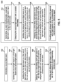
- FIG. 5 illustrates a flowchart of an example time-domain optical coherence tomography method 500, according to an embodiment of the invention.
- a source light beam is generated.
- the source light beam is split into a first light beam and a second light beam.
- the first light beam is split into a first set of light beams, such that each light beam in the first set corresponds to a respective interferometer in a set of interferometers.
- each light beam in the first set of light beams is delayed, by a time delay, such that any significant multiple scattering contributions from the delayed light beams are out of coherence with respect to each other, as described above.
- each delayed light beam in the first set of light beams is input to its corresponding interferometer.
- each interferometer generates a sample light beam, using the delayed light beam input to the interferometer.
- the second light beam is delayed with a variable time delay.
- the delayed second light beam is split into a second set of light beams, each light beam in the second set corresponding to an interferometer in a set of interferometers.
- each delayed light beam in the second set of light beams is input to its corresponding interferometer as a reference signal.
- inventions may include free-space optics OCT implementations (Full Field) using modulation of group delay or phase applied through a spatial dense 2D modulator.
- wave guide paths may be replaced by optical beam sections.
Landscapes
- Physics & Mathematics (AREA)
- Health & Medical Sciences (AREA)
- General Physics & Mathematics (AREA)
- Life Sciences & Earth Sciences (AREA)
- Nuclear Medicine, Radiotherapy & Molecular Imaging (AREA)
- Radiology & Medical Imaging (AREA)
- General Health & Medical Sciences (AREA)
- Engineering & Computer Science (AREA)
- Pathology (AREA)
- Biomedical Technology (AREA)
- Heart & Thoracic Surgery (AREA)
- Medical Informatics (AREA)
- Molecular Biology (AREA)
- Surgery (AREA)
- Animal Behavior & Ethology (AREA)
- Biophysics (AREA)
- Public Health (AREA)
- Veterinary Medicine (AREA)
- Investigating Or Analysing Materials By Optical Means (AREA)
Claims (15)
- System (300) zur optischen Kohärenztomographie im Zeitbereich, aufweisend:eine Quelle (302), die dafür ausgelegt ist, ein Strahlenbündel zu erzeugen;einen ersten Splitter (306), der dafür ausgelegt ist, das Strahlenbündel in ein erstes Strahlenbündel und ein zweites Strahlenbündel zu teilen;einen zweiten Splitter (308), der dafür ausgelegt ist, das erste Strahlenbündel in mindestens ein drittes Strahlenbündel und ein viertes Strahlenbündel zu teilen;ein erstes Verzögerungselement (320_1), das dafür ausgelegt ist, das dritte Strahlenbündel mit einer ersten Zeitverzögerung (τ1) zu verzögern;ein zweites Verzögerungselement (320_2), das dafür ausgelegt ist, das vierte Strahlenbündel mit einer zweiten Zeitverzögerung (τ2) zu verzögern, so dass das verzögerte dritte Strahlenbündel und das verzögerte vierte Strahlenbündel nicht miteinander kohärent sind;ein erstes Interferometer (314_1), das dafür ausgelegt ist, das verzögerte dritte Strahlenbündel als einen Eingang zu empfangen, wobei das erste Interferometer aufweist:einen ersten Mischsplitter (322_1), der ausgelegt ist zum:Empfangen des verzögerten dritten Strahlenbündels und Erzeugen eines ersten Abtaststrahlenbündels; und zumEmpfangen eines gestreuten Abtaststrahlenbündels von einer Probe; undeinen zweiten Mischsplitter (324_1), der ausgelegt ist zum:Empfangen des gestreuten Abtaststrahlenbündels vom ersten Mischsplitter;Empfangen eines ersten Referenzeingangs basierend auf dem zweiten Strahlenbündel vom ersten Splitter; undein zweites Interferometer (314_2), das dafür ausgelegt ist, das verzögerte vierte Strahlenbündel als einen Eingang und einen zweiten Referenzeingang basierend auf dem zweiten Strahlenbündel vom ersten Splitter zu empfangen,wobei das zweite Interferometer (314_2) einen dritten Mischsplitter (322_2) aufweist, der dafür ausgelegt ist, das verzögerte vierte Strahlenbündel zu empfangen und ein zweites Abtaststrahlenbündel zu erzeugen,wobei das System darüber hinaus aufweist:ein variables Verzögerungselement (310), das dafür ausgelegt ist, das zweite Strahlenbündel um eine variable Verzögerung zu verzögern;einen dritten Splitter (312), der dafür ausgelegt ist, das verzögerte zweite Strahlenbündel in mindestens ein fünftes Strahlenbündel und ein sechstes Strahlenbündel zu teilen;ein drittes Verzögerungselement (318_1), das dafür ausgelegt ist, das fünfte Strahlenbündel um die erste Zeitverzögerung (τ1) zu verzögern; undein viertes Verzögerungselement (318_2), das dafür ausgelegt ist, das sechste Strahlenbündel um die zweite Zeitverzögerung (τ2) zu verzögern,wobei das erste Interferometer (314_1) darüber hinaus dafür ausgelegt ist, das verzögerte fünfte Strahlenbündel als den ersten Referenzeingang zu empfangen, undwobei das zweite Interferometer (314_2) darüber hinaus dafür ausgelegt ist, das verzögerte sechste Strahlenbündel als den zweiten Referenzeingang zu empfangen.
- System nach Anspruch 1, wobei eine Differenz zwischen der ersten Zeitverzögerung und der zweiten Zeitverzögerung groß genug ist, um für eine unsymmetrische Eigenschaft einer Mehrfachstreuung verantwortlich zu sein, die durch das dritte Strahlenbündel verursacht wird.
- System nach Anspruch 1, wobei der zweite Splitter (308) darüber hinaus dafür ausgelegt ist, das erste Strahlenbündel in ein siebtes Strahlenbündel zu teilen.
- System nach Anspruch 3, darüber hinaus aufweisend:eine fünftes Verzögerungselement (320_3), das dafür ausgelegt ist, das siebte Strahlenbündel mit einer dritten Zeitverzögerung zu verzögern, so dass das verzögerte siebte Strahlenbündel nicht mehr mit dem verzögerten dritten Strahlenbündel und dem verzögerten vierten Strahlenbündel kohärent ist; undein drittes Interferometer (314_3), das dafür ausgelegt ist, das verzögerte siebte Strahlenbündel als einen Eingang zu empfangen.
- System nach Anspruch 4, wobei Differenzen zwischen der dritten Zeitverzögerung und der ersten Zeitverzögerung sowie zwischen der dritten Zeitverzögerung und der zweiten Zeitverzögerung groß genug sind, um für unsymmetrische Eigenschaften einer Mehrfachstreuung verantwortlich zu sein, die durch das verzögerte dritte Strahlenbündel bzw. das verzögerte vierte Strahlenbündel verursacht werden.
- System nach Anspruch 4, wobei das dritte Interferometer (314_3) einen vierten Mischsplitter (322_3) aufweist, der dafür ausgelegt ist, das verzögerte siebte Strahlenbündel zu empfangen und ein drittes Abtaststrahlenbündel zu erzeugen.
- System nach Anspruch 6, wobei der dritte Splitter (312) darüber hinaus dafür ausgelegt ist, das verzögerte zweite Strahlenbündel in ein achtes Strahlenbündel zu teilen.
- System nach Anspruch 7, darüber hinaus aufweisend:
ein sechstes Verzögerungselement (318_3), das dafür ausgelegt ist, das achte Strahlenbündel mit der dritten Zeitverzögerung zu verzögern. - System nach Anspruch 8, wobei das dritte Interferometer (314_3) darüber hinaus dafür ausgelegt ist, das verzögerte achte Strahlenbündel als einen Referenzeingang zu empfangen.
- System nach Anspruch 1, wobei die erste Zeitverzögerung gleich Null ist.
- Verfahren zum Durchführen einer optischen Kohärenztomographie im Zeitbereich unter Verwendung des Systems nach einem der Ansprüche 1 bis 10, wobei das Verfahren umfasst:Erzeugen eines Quellenstrahlenbündels;Teilen des Quellenstrahlenbündels in ein erstes Strahlenbündel und ein zweites Strahlenbündel;Teilen des ersten Strahlenbündels in mindestens ein drittes Strahlenbündel und ein viertes Strahlenbündel;Verzögern des dritten Strahlenbündels um eine erste Zeitverzögerung (τ1);Verzögern des vierten Strahlenbündels um eine zweite Zeitverzögerung (τ2), so dass das verzögerte dritte Strahlenbündel und das verzögerte vierte Strahlenbündel nicht mehr miteinander kohärent sind;Eingeben des verzögerten dritten Strahlenbündels in ein erstes Interferometer (314_1), das einen ersten Mischsplitter (322_1) und einen zweiten Mischsplitter (324_1) aufweist;Erzeugen, durch den ersten Mischsplitter (322_1) des ersten Interferometers (314_1), eines ersten Abtaststrahlenbündels unter Verwendung des verzögerten dritten Strahlenbündels;Empfangen, durch den zweiten Mischsplitter (324_1) des ersten Interferometers (314_1), eines gestreuten Abtaststrahlenbündels von einer Probe vom ersten Mischsplitter;
undEingeben des verzögerten vierten Strahlenbündels in ein zweites Interferometer (314_2) und Erzeugen eines zweiten Abtaststrahlenbündels durch das zweite Interferometer (314_2) unter Verwendung des verzögerten vierten Strahlenbündels,Verzögern des zweiten Strahlenbündels mit einer variablen Zeitverzögerung;Teilen des verzögerten zweiten Strahlenbündels in mindestens ein fünftes Strahlenbündel und ein sechstes Strahlenbündel;Verzögern des fünften Strahlenbündels um die erste Zeitverzögerung (τ1);Eingeben des verzögerten fünften Strahlenbündels in das erste Interferometer (314_1) als ein erstes Referenzstrahlenbündel;Verzögern des sechsten Strahlenbündels um die zweite Zeitverzögerung (τ2); undEingeben des verzögerten sechsten Strahlenbündels in das zweite Interferometer (314_2) als ein zweites Referenzstrahlenbündel. - Verfahren nach Anspruch 11, wobei eine Differenz zwischen der ersten Zeitverzögerung und der zweiten Zeitverzögerung groß genug ist, um für eine unsymmetrische Eigenschaft einer Mehrfachstreuung verantwortlich zu sein, die durch das dritte Strahlenbündel verursacht wird.
- Verfahren nach Anspruch 11, darüber hinaus umfassend:weiteres Teilen des ersten Strahlenbündels in ein siebtes Strahlenbündel;Verzögern des siebten Strahlenbündels um eine dritte Zeitverzögerung, so dass das verzögerte siebte Strahlenbündel nicht mehr mit dem verzögerten dritten Strahlenbündel und dem verzögerten vierten Strahlenbündel kohärent ist;Eingeben des verzögerten siebten Strahlenbündels in ein drittes Interferometer (314_3); undErzeugen eines dritten Abtaststrahlenbündels durch das dritte Interferometer (314_3) unter Verwendung des verzögerten siebten Strahlenbündels.
- Verfahren nach Anspruch 13, wobei Differenzen zwischen der dritten Zeitverzögerung und der ersten Zeitverzögerung sowie zwischen der dritten Zeitverzögerung und der zweiten Zeitverzögerung groß genug sind, um für unsymmetrische Eigenschaften einer Mehrfachstreuung verantwortlich zu sein, die durch das dritte Strahlenbündel bzw. das vierte Strahlenbündel verursacht werden.
- Verfahren nach Anspruch 13, darüber hinaus umfassend:weiteres Teilen des verzögerten zweiten Strahlenbündels in ein achtes Strahlenbündel;Verzögern des achten Strahlenbündels um die dritte Zeitverzögerung, so dass das verzögerte achte Strahlenbündel nicht mehr mit dem verzögerten fünften Strahlenbündel und dem verzögerten sechsten Strahlenbündel kohärent ist; undEingeben des verzögerten achten Strahlenbündels in das dritte Interferometer als ein drittes Referenzstrahlenbündel.
Priority Applications (1)
| Application Number | Priority Date | Filing Date | Title |
|---|---|---|---|
| EP24196329.7A EP4517254A3 (de) | 2015-07-22 | 2016-07-20 | Optische hochgeschwindigkeitskohärenztomografie mit mehreren interferometern mit unterdrücktem mehrfachstreuungsübersprechen |
Applications Claiming Priority (3)
| Application Number | Priority Date | Filing Date | Title |
|---|---|---|---|
| US201562195573P | 2015-07-22 | 2015-07-22 | |
| US15/213,293 US9869541B2 (en) | 2015-07-22 | 2016-07-18 | High-speed optical coherence tomography using multiple interferometers with suppressed multiple scattering cross-talk |
| PCT/EP2016/067313 WO2017013177A1 (en) | 2015-07-22 | 2016-07-20 | High-speed optical coherence tomography using multiple interferometers with suppressed multiple scattering cross-talk |
Related Child Applications (1)
| Application Number | Title | Priority Date | Filing Date |
|---|---|---|---|
| EP24196329.7A Division EP4517254A3 (de) | 2015-07-22 | 2016-07-20 | Optische hochgeschwindigkeitskohärenztomografie mit mehreren interferometern mit unterdrücktem mehrfachstreuungsübersprechen |
Publications (3)
| Publication Number | Publication Date |
|---|---|
| EP3325915A1 EP3325915A1 (de) | 2018-05-30 |
| EP3325915C0 EP3325915C0 (de) | 2024-08-28 |
| EP3325915B1 true EP3325915B1 (de) | 2024-08-28 |
Family
ID=56511568
Family Applications (2)
| Application Number | Title | Priority Date | Filing Date |
|---|---|---|---|
| EP16741928.2A Active EP3325915B1 (de) | 2015-07-22 | 2016-07-20 | Optische hochgeschwindigkeitskohärenztomografie mit mehreren interferometern mit unterdrücktem mehrfachstreuungsübersprechen |
| EP24196329.7A Withdrawn EP4517254A3 (de) | 2015-07-22 | 2016-07-20 | Optische hochgeschwindigkeitskohärenztomografie mit mehreren interferometern mit unterdrücktem mehrfachstreuungsübersprechen |
Family Applications After (1)
| Application Number | Title | Priority Date | Filing Date |
|---|---|---|---|
| EP24196329.7A Withdrawn EP4517254A3 (de) | 2015-07-22 | 2016-07-20 | Optische hochgeschwindigkeitskohärenztomografie mit mehreren interferometern mit unterdrücktem mehrfachstreuungsübersprechen |
Country Status (8)
| Country | Link |
|---|---|
| US (1) | US9869541B2 (de) |
| EP (2) | EP3325915B1 (de) |
| JP (1) | JP6453519B2 (de) |
| CN (1) | CN108139199B (de) |
| AU (2) | AU2016296781A1 (de) |
| BR (1) | BR112018001315B1 (de) |
| CA (1) | CA2993268C (de) |
| WO (1) | WO2017013177A1 (de) |
Families Citing this family (5)
| Publication number | Priority date | Publication date | Assignee | Title |
|---|---|---|---|---|
| EP3734252A4 (de) * | 2017-12-25 | 2021-02-24 | NEC Corporation | Steuergerät optischer strahlen und vorrichtung zur tomografiebildgebung mit optischen interferenzen mit verwendung davon |
| JP6803887B2 (ja) * | 2018-10-10 | 2020-12-23 | 株式会社吉田製作所 | 光干渉断層画像生成装置 |
| KR101990251B1 (ko) | 2018-10-15 | 2019-06-17 | 경북대학교 산학협력단 | 광 간섭성 단층 촬영 장치 및 이를 이용한 영상 생성 방법 |
| AU2020405254A1 (en) * | 2019-12-20 | 2022-05-12 | The General Hospital Corporation | Systems, methods, and media for multiple beam optical coherence tomography |
| WO2023275929A1 (ja) * | 2021-06-28 | 2023-01-05 | 日本電気株式会社 | 光干渉断層撮像装置、光干渉断層撮像方法、及び記録媒体 |
Citations (2)
| Publication number | Priority date | Publication date | Assignee | Title |
|---|---|---|---|---|
| US20120026463A1 (en) * | 2009-05-08 | 2012-02-02 | Canon Kabushiki Kaisha | Optical coherence tomographic imaging apparatus |
| WO2014088650A1 (en) * | 2012-12-06 | 2014-06-12 | Lehigh University | Space-division multiplexing optical coherence tomography apparatus |
Family Cites Families (14)
| Publication number | Priority date | Publication date | Assignee | Title |
|---|---|---|---|---|
| US4748686A (en) * | 1986-10-15 | 1988-05-31 | United Technologies Corporation | Coherence multiplexed optical position transducer |
| US6332093B1 (en) * | 1998-08-06 | 2001-12-18 | Art Recherches Et Technologies Avancees Inc./Art Advanced Research Technologies, Inc. | Scanning module for imaging through scattering media |
| EP1713377A1 (de) * | 2004-02-10 | 2006-10-25 | Optovue, Inc. | Hochleistungsfähige interferometrie mit niedriger kohärenz |
| JP5627259B2 (ja) * | 2009-05-22 | 2014-11-19 | キヤノン株式会社 | 撮像装置及び撮像方法 |
| JP5645445B2 (ja) * | 2009-05-22 | 2014-12-24 | キヤノン株式会社 | 撮像装置及び撮像方法 |
| JP2010276462A (ja) | 2009-05-28 | 2010-12-09 | Sumitomo Electric Ind Ltd | Oct装置 |
| JP2011214969A (ja) * | 2010-03-31 | 2011-10-27 | Canon Inc | 撮像装置及び撮像方法 |
| JP2012042348A (ja) * | 2010-08-19 | 2012-03-01 | Canon Inc | 断層画像表示装置およびその制御方法 |
| ES2497190T3 (es) * | 2011-04-06 | 2014-09-22 | Agfa Healthcare N.V. | Sistema y procedimiento para tomografía de coherencia óptica |
| ES2415555B2 (es) * | 2011-05-20 | 2014-07-09 | Medlumics, S.L. | Dispositivo de barrido para interferometría de baja coherencia. |
| ES2396391B2 (es) * | 2011-06-28 | 2014-12-04 | Medlumics, S.L. | Dispositivo de retardo óptico variable para interferometría de baja coherencia. |
| JP2013160699A (ja) * | 2012-02-08 | 2013-08-19 | Hitachi High-Technologies Corp | 光断層画像測定装置 |
| CN104870930A (zh) | 2012-12-06 | 2015-08-26 | 周超 | 并行成像光学相干断层扫描系统及方法 |
| US9200888B2 (en) * | 2013-11-01 | 2015-12-01 | Tomey Corporation | Multi-channel optical coherence tomography |
-
2016
- 2016-07-18 US US15/213,293 patent/US9869541B2/en active Active
- 2016-07-20 JP JP2018503251A patent/JP6453519B2/ja active Active
- 2016-07-20 WO PCT/EP2016/067313 patent/WO2017013177A1/en not_active Ceased
- 2016-07-20 EP EP16741928.2A patent/EP3325915B1/de active Active
- 2016-07-20 AU AU2016296781A patent/AU2016296781A1/en not_active Abandoned
- 2016-07-20 CN CN201680051536.3A patent/CN108139199B/zh active Active
- 2016-07-20 EP EP24196329.7A patent/EP4517254A3/de not_active Withdrawn
- 2016-07-20 BR BR112018001315-3A patent/BR112018001315B1/pt active IP Right Grant
- 2016-07-20 CA CA2993268A patent/CA2993268C/en active Active
-
2021
- 2021-11-24 AU AU2021273569A patent/AU2021273569B2/en active Active
Patent Citations (2)
| Publication number | Priority date | Publication date | Assignee | Title |
|---|---|---|---|---|
| US20120026463A1 (en) * | 2009-05-08 | 2012-02-02 | Canon Kabushiki Kaisha | Optical coherence tomographic imaging apparatus |
| WO2014088650A1 (en) * | 2012-12-06 | 2014-06-12 | Lehigh University | Space-division multiplexing optical coherence tomography apparatus |
Also Published As
| Publication number | Publication date |
|---|---|
| CA2993268C (en) | 2024-02-20 |
| WO2017013177A1 (en) | 2017-01-26 |
| AU2021273569B2 (en) | 2024-01-11 |
| JP2018521326A (ja) | 2018-08-02 |
| AU2021273569A1 (en) | 2021-12-16 |
| BR112018001315A2 (pt) | 2018-09-11 |
| EP3325915A1 (de) | 2018-05-30 |
| JP6453519B2 (ja) | 2019-01-16 |
| EP4517254A3 (de) | 2025-04-23 |
| AU2016296781A1 (en) | 2018-03-15 |
| CN108139199B (zh) | 2020-12-25 |
| EP3325915C0 (de) | 2024-08-28 |
| CN108139199A (zh) | 2018-06-08 |
| EP4517254A2 (de) | 2025-03-05 |
| US20170023350A1 (en) | 2017-01-26 |
| US9869541B2 (en) | 2018-01-16 |
| CA2993268A1 (en) | 2017-01-26 |
| BR112018001315B1 (pt) | 2022-12-20 |
Similar Documents
| Publication | Publication Date | Title |
|---|---|---|
| AU2021273569B2 (en) | High-speed optical coherence tomography using multiple interferometers with suppressed multiple scattering cross-talk | |
| US6992776B2 (en) | Method for studying a sample and optical interferometer for doing the same | |
| US7728985B2 (en) | Polarization-sensitive common path optical coherence reflectometry/tomography device | |
| JP4494160B2 (ja) | 光画像計測装置 | |
| TWI397715B (zh) | 使用頻率域干涉法用以執行光學成像之方法及設備 | |
| JP5939866B2 (ja) | 光干渉断層撮像装置及び撮像方法 | |
| JP4869896B2 (ja) | 光断層画像化装置 | |
| EP2719324B1 (de) | Vorrichtung für optische kohärenztomographie | |
| JP7617107B2 (ja) | マルチビーム光コヒーレンストモグラフィのためのシステム、方法及び媒体 | |
| Ahmad et al. | Ultra-short longitudinal spatial coherence length of laser light with the combined effect of spatial, angular, and temporal diversity | |
| KR101544962B1 (ko) | 기하학적 두께와 굴절률 측정을 위한 투과형 광섬유 간섭 장치 | |
| JP7120400B2 (ja) | 光干渉断層撮像器 | |
| KR101882769B1 (ko) | 주파수 분할 다중화방식의 광단층 영상장치 | |
| JP2017111062A (ja) | 光干渉断層計 | |
| JP2014092425A (ja) | 光干渉断層撮像装置及び光干渉断層撮像方法 | |
| Dashtabi et al. | Space division multiplexed optical coherence tomography on a silicon Chip―an experimental and numerical analysis of potential artifacts |
Legal Events
| Date | Code | Title | Description |
|---|---|---|---|
| STAA | Information on the status of an ep patent application or granted ep patent |
Free format text: STATUS: THE INTERNATIONAL PUBLICATION HAS BEEN MADE |
|
| PUAI | Public reference made under article 153(3) epc to a published international application that has entered the european phase |
Free format text: ORIGINAL CODE: 0009012 |
|
| STAA | Information on the status of an ep patent application or granted ep patent |
Free format text: STATUS: REQUEST FOR EXAMINATION WAS MADE |
|
| 17P | Request for examination filed |
Effective date: 20180222 |
|
| AK | Designated contracting states |
Kind code of ref document: A1 Designated state(s): AL AT BE BG CH CY CZ DE DK EE ES FI FR GB GR HR HU IE IS IT LI LT LU LV MC MK MT NL NO PL PT RO RS SE SI SK SM TR |
|
| AX | Request for extension of the european patent |
Extension state: BA ME |
|
| DAV | Request for validation of the european patent (deleted) | ||
| DAX | Request for extension of the european patent (deleted) | ||
| STAA | Information on the status of an ep patent application or granted ep patent |
Free format text: STATUS: EXAMINATION IS IN PROGRESS |
|
| 17Q | First examination report despatched |
Effective date: 20190516 |
|
| RAP1 | Party data changed (applicant data changed or rights of an application transferred) |
Owner name: MEDLUMICS S.L. |
|
| REG | Reference to a national code |
Ref country code: DE Ref legal event code: R079 Free format text: PREVIOUS MAIN CLASS: G01B0009020000 Ipc: G01B0009020150 Ref document number: 602016089115 Country of ref document: DE |
|
| GRAP | Despatch of communication of intention to grant a patent |
Free format text: ORIGINAL CODE: EPIDOSNIGR1 |
|
| STAA | Information on the status of an ep patent application or granted ep patent |
Free format text: STATUS: GRANT OF PATENT IS INTENDED |
|
| RIC1 | Information provided on ipc code assigned before grant |
Ipc: A61B 5/00 20060101ALN20240315BHEP Ipc: A61B 3/10 20060101ALN20240315BHEP Ipc: G01B 9/02091 20220101ALI20240315BHEP Ipc: G01B 9/02056 20220101ALI20240315BHEP Ipc: G01B 9/02055 20220101ALI20240315BHEP Ipc: G01B 9/02015 20220101AFI20240315BHEP |
|
| INTG | Intention to grant announced |
Effective date: 20240417 |
|
| RIC1 | Information provided on ipc code assigned before grant |
Ipc: A61B 5/00 20060101ALN20240408BHEP Ipc: A61B 3/10 20060101ALN20240408BHEP Ipc: G01B 9/02091 20220101ALI20240408BHEP Ipc: G01B 9/02056 20220101ALI20240408BHEP Ipc: G01B 9/02055 20220101ALI20240408BHEP Ipc: G01B 9/02015 20220101AFI20240408BHEP |
|
| GRAS | Grant fee paid |
Free format text: ORIGINAL CODE: EPIDOSNIGR3 |
|
| GRAA | (expected) grant |
Free format text: ORIGINAL CODE: 0009210 |
|
| STAA | Information on the status of an ep patent application or granted ep patent |
Free format text: STATUS: THE PATENT HAS BEEN GRANTED |
|
| AK | Designated contracting states |
Kind code of ref document: B1 Designated state(s): AL AT BE BG CH CY CZ DE DK EE ES FI FR GB GR HR HU IE IS IT LI LT LU LV MC MK MT NL NO PL PT RO RS SE SI SK SM TR |
|
| REG | Reference to a national code |
Ref country code: GB Ref legal event code: FG4D |
|
| REG | Reference to a national code |
Ref country code: CH Ref legal event code: EP |
|
| REG | Reference to a national code |
Ref country code: DE Ref legal event code: R096 Ref document number: 602016089115 Country of ref document: DE |
|
| REG | Reference to a national code |
Ref country code: IE Ref legal event code: FG4D |
|
| U01 | Request for unitary effect filed |
Effective date: 20240926 |
|
| U07 | Unitary effect registered |
Designated state(s): AT BE BG DE DK EE FI FR IT LT LU LV MT NL PT RO SE SI Effective date: 20241018 |
|
| PG25 | Lapsed in a contracting state [announced via postgrant information from national office to epo] |
Ref country code: NO Free format text: LAPSE BECAUSE OF FAILURE TO SUBMIT A TRANSLATION OF THE DESCRIPTION OR TO PAY THE FEE WITHIN THE PRESCRIBED TIME-LIMIT Effective date: 20241128 |
|
| PG25 | Lapsed in a contracting state [announced via postgrant information from national office to epo] |
Ref country code: PL Free format text: LAPSE BECAUSE OF FAILURE TO SUBMIT A TRANSLATION OF THE DESCRIPTION OR TO PAY THE FEE WITHIN THE PRESCRIBED TIME-LIMIT Effective date: 20240828 |
|
| PG25 | Lapsed in a contracting state [announced via postgrant information from national office to epo] |
Ref country code: IS Free format text: LAPSE BECAUSE OF FAILURE TO SUBMIT A TRANSLATION OF THE DESCRIPTION OR TO PAY THE FEE WITHIN THE PRESCRIBED TIME-LIMIT Effective date: 20241228 |
|
| PG25 | Lapsed in a contracting state [announced via postgrant information from national office to epo] |
Ref country code: HR Free format text: LAPSE BECAUSE OF FAILURE TO SUBMIT A TRANSLATION OF THE DESCRIPTION OR TO PAY THE FEE WITHIN THE PRESCRIBED TIME-LIMIT Effective date: 20240828 |
|
| PG25 | Lapsed in a contracting state [announced via postgrant information from national office to epo] |
Ref country code: RS Free format text: LAPSE BECAUSE OF FAILURE TO SUBMIT A TRANSLATION OF THE DESCRIPTION OR TO PAY THE FEE WITHIN THE PRESCRIBED TIME-LIMIT Effective date: 20241128 Ref country code: ES Free format text: LAPSE BECAUSE OF FAILURE TO SUBMIT A TRANSLATION OF THE DESCRIPTION OR TO PAY THE FEE WITHIN THE PRESCRIBED TIME-LIMIT Effective date: 20240828 |
|
| PG25 | Lapsed in a contracting state [announced via postgrant information from national office to epo] |
Ref country code: RS Free format text: LAPSE BECAUSE OF FAILURE TO SUBMIT A TRANSLATION OF THE DESCRIPTION OR TO PAY THE FEE WITHIN THE PRESCRIBED TIME-LIMIT Effective date: 20241128 Ref country code: PL Free format text: LAPSE BECAUSE OF FAILURE TO SUBMIT A TRANSLATION OF THE DESCRIPTION OR TO PAY THE FEE WITHIN THE PRESCRIBED TIME-LIMIT Effective date: 20240828 Ref country code: NO Free format text: LAPSE BECAUSE OF FAILURE TO SUBMIT A TRANSLATION OF THE DESCRIPTION OR TO PAY THE FEE WITHIN THE PRESCRIBED TIME-LIMIT Effective date: 20241128 Ref country code: IS Free format text: LAPSE BECAUSE OF FAILURE TO SUBMIT A TRANSLATION OF THE DESCRIPTION OR TO PAY THE FEE WITHIN THE PRESCRIBED TIME-LIMIT Effective date: 20241228 Ref country code: HR Free format text: LAPSE BECAUSE OF FAILURE TO SUBMIT A TRANSLATION OF THE DESCRIPTION OR TO PAY THE FEE WITHIN THE PRESCRIBED TIME-LIMIT Effective date: 20240828 Ref country code: ES Free format text: LAPSE BECAUSE OF FAILURE TO SUBMIT A TRANSLATION OF THE DESCRIPTION OR TO PAY THE FEE WITHIN THE PRESCRIBED TIME-LIMIT Effective date: 20240828 |
|
| PG25 | Lapsed in a contracting state [announced via postgrant information from national office to epo] |
Ref country code: SM Free format text: LAPSE BECAUSE OF FAILURE TO SUBMIT A TRANSLATION OF THE DESCRIPTION OR TO PAY THE FEE WITHIN THE PRESCRIBED TIME-LIMIT Effective date: 20240828 |
|
| PG25 | Lapsed in a contracting state [announced via postgrant information from national office to epo] |
Ref country code: CZ Free format text: LAPSE BECAUSE OF FAILURE TO SUBMIT A TRANSLATION OF THE DESCRIPTION OR TO PAY THE FEE WITHIN THE PRESCRIBED TIME-LIMIT Effective date: 20240828 |
|
| PG25 | Lapsed in a contracting state [announced via postgrant information from national office to epo] |
Ref country code: SK Free format text: LAPSE BECAUSE OF FAILURE TO SUBMIT A TRANSLATION OF THE DESCRIPTION OR TO PAY THE FEE WITHIN THE PRESCRIBED TIME-LIMIT Effective date: 20240828 |
|
| PLBE | No opposition filed within time limit |
Free format text: ORIGINAL CODE: 0009261 |
|
| STAA | Information on the status of an ep patent application or granted ep patent |
Free format text: STATUS: NO OPPOSITION FILED WITHIN TIME LIMIT |
|
| 26N | No opposition filed |
Effective date: 20250530 |
|
| U20 | Renewal fee for the european patent with unitary effect paid |
Year of fee payment: 10 Effective date: 20250729 |
|
| REG | Reference to a national code |
Ref country code: CH Ref legal event code: H13 Free format text: ST27 STATUS EVENT CODE: U-0-0-H10-H13 (AS PROVIDED BY THE NATIONAL OFFICE) Effective date: 20260224 |
|
| GBPC | Gb: european patent ceased through non-payment of renewal fee |
Effective date: 20250720 |
|
| PG25 | Lapsed in a contracting state [announced via postgrant information from national office to epo] |
Ref country code: GB Free format text: LAPSE BECAUSE OF NON-PAYMENT OF DUE FEES Effective date: 20250720 |
|
| PG25 | Lapsed in a contracting state [announced via postgrant information from national office to epo] |
Ref country code: CH Free format text: LAPSE BECAUSE OF NON-PAYMENT OF DUE FEES Effective date: 20250731 |