EP3325901B1 - Füllvorrichtung zum befüllen eines einem kühlbehälter zugeordneten kältemittel-aufnahmefachs mit einem kryogenen kältemittel - Google Patents
Füllvorrichtung zum befüllen eines einem kühlbehälter zugeordneten kältemittel-aufnahmefachs mit einem kryogenen kältemittel Download PDFInfo
- Publication number
- EP3325901B1 EP3325901B1 EP16742299.7A EP16742299A EP3325901B1 EP 3325901 B1 EP3325901 B1 EP 3325901B1 EP 16742299 A EP16742299 A EP 16742299A EP 3325901 B1 EP3325901 B1 EP 3325901B1
- Authority
- EP
- European Patent Office
- Prior art keywords
- filling
- carbon dioxide
- nozzle
- pistol
- receiving compartment
- Prior art date
- Legal status (The legal status is an assumption and is not a legal conclusion. Google has not performed a legal analysis and makes no representation as to the accuracy of the status listed.)
- Active
Links
Images


Classifications
-
- F—MECHANICAL ENGINEERING; LIGHTING; HEATING; WEAPONS; BLASTING
- F25—REFRIGERATION OR COOLING; COMBINED HEATING AND REFRIGERATION SYSTEMS; HEAT PUMP SYSTEMS; MANUFACTURE OR STORAGE OF ICE; LIQUEFACTION SOLIDIFICATION OF GASES
- F25D—REFRIGERATORS; COLD ROOMS; ICE-BOXES; COOLING OR FREEZING APPARATUS NOT OTHERWISE PROVIDED FOR
- F25D3/00—Devices using other cold materials; Devices using cold-storage bodies
- F25D3/12—Devices using other cold materials; Devices using cold-storage bodies using solidified gases, e.g. carbon-dioxide snow
- F25D3/125—Movable containers
Definitions
- the invention relates to a filling device for filling a refrigerant receiving compartment assigned to a cooling container for cooling products with carbon dioxide snow, with a supply unit and a filling pistol that can be coupled to the supply unit, the filling pistol having an expansion nozzle that can be connected to at least one filling opening of the refrigerant receiving compartment for supplying liquid Has carbon dioxide and a suction opening that can be connected to a gas outlet opening of the refrigerant receiving compartment for discharging gaseous carbon dioxide and is connected to the supply unit via a carbon dioxide liquid feed line that is flow-connected to the filling opening and a suction line that is flow-connected to the suction opening, and with a control valve for regulating the supply of liquid carbon dioxide into the carbon dioxide liquid feed line, a suction device for sucking off gaseous carbon dioxide from the suction line and a control and monitoring unit for Control the filling process.
- Mobile isothermal cooling containers are used to transport heat-sensitive products, in particular food such as fresh or frozen products, with which a seamless cooling chain from production to the end customer is to be ensured even if permanent cooling by an electrically operated cooling device is not possible is.
- Such mobile cooling containers have a product receiving compartment for storing the products to be kept cool and a refrigerant receiving compartment for a cryogenic refrigerant that is spatially separated from this but is thermally connected to it.
- the refrigerant absorbs heat that penetrates through the walls of the container and thus ensures that the temperature in the product receiving compartment does not rise and the product is kept at a low temperature. This leads to gradual evaporation or sublimation of the refrigerant.
- the product can in this way be kept at a certain low temperature for many hours without the need for a permanent external energy supply.
- the cooler of the talk standing type are dimensioned so that they can easily be moved by one person by means of wheels attached to them.
- Typical cooling containers have, for example, a base area based on the European pallet standard of 600 mm x 800 mm to 1200 mm x 800 mm and a height between 1000 mm and 2000 mm and a useful volume of, for example, between 200 liters and 1500 liters.
- the compartment for the refrigerant is much smaller than the compartment for receiving the products and has, for example a volume between 5 liters and 50 liters.
- the present invention relates to a filling device for filling such refrigerant receiving compartments.
- a cooling container of the aforementioned type is for example from EP 0 942 244 A1 known.
- the container has a drawer-like refrigerant receptacle for carbon dioxide snow, which is thermally and fluidically connected to a product receptacle arranged below.
- the refrigerant storage compartment is loaded with carbon dioxide snow with a temperature of -78 ° C, which absorbs heat penetrating into the cooling container and gradually sublimates in the process. Due to a suitable setting of the heat transfer between the compartments, the products can be reliably kept at a temperature of, for example, 0 ° C to 5 ° C (for fresh goods) or -15 ° C to -25 ° C (frozen goods) for more than 24 hours.
- the filling device has a filling pistol and a supply unit connected to it.
- the filling pistol is equipped with an expansion nozzle which is inserted into a filling opening of the refrigerant receiving compartment, as well as with an exhaust device which is connected to a gas exhaust opening of the refrigerant receiving compartment.
- liquid carbon dioxide is supplied which, when exiting the expansion nozzle, expands with strong cooling, a mixture of carbon dioxide snow and carbon dioxide gas being formed.
- the filling pistol is equipped with connection fittings with which the filling pistol is connected to the refrigerant receiving compartment in a substantially gas-tight manner and which ensure that as no carbon dioxide as possible escapes into the vicinity of the container during the filling process. Since the carbon dioxide is supplied at high pressure, the filling pistol is also equipped with electromagnets that establish a secure connection with the refrigerant compartment.
- a control valve arranged in the filling pistol, which regulates the supply of carbon dioxide, can only be opened when a correct connection is established via electrical detectors likewise arranged in the filling pistol.
- the supply unit comprises supply and discharge lines for the carbon dioxide, a control unit electrically connected to the control valve, the electromagnets and the detectors, and a mechanical holding device which enables the filling gun to be operated with one hand.
- the filling devices known from the prior art often have the disadvantage that the impulse flow of the carbon dioxide emerging from the expansion nozzle at high pressure exerts a force on the expansion nozzle, which forces it out of the refrigerant receiving compartment.
- strong electromagnets are used which are switched on before the filling process begins and, in cooperation with a ferromagnetic element on the coolant receiving compartment, ensure a firm connection.
- the electrical feeds and connections inside the filling pistol required to operate the electromagnets must, however, be protected in a complex manner against moisture, temperature fluctuations and electrostatic charges, so that these filling pistols are very complex in construction and have a high dead weight, which makes them difficult to handle.
- the object of the present invention is therefore to create a filling system for filling a refrigerant receiving compartment assigned to a cooling container for cooling products with carbon dioxide snow, in which the risk of the filling pistol being forced out of the refrigerant receiving compartment during the filling process is minimized, and in which the generated carbon dioxide snow is evenly distributed inside the snow storage compartment.
- a front section of the expansion nozzle is equipped with at least two nozzle heads arranged parallel to one another, which protrude into the interior of the refrigerant receiving compartment during filling and which each have at least one nozzle opening, the nozzle openings of the nozzle heads being directed towards one another in such a way that in use the expansion nozzle at least largely cancel out the impulse flows of the carbon dioxide jets emerging from the nozzle openings.
- the expansion nozzle at least largely cancel out the impulse flows of the carbon dioxide jets emerging from the nozzle openings.
- the nozzle heads are preferably designed symmetrically to one another, so each have similar nozzle openings, which are each arranged at the same distance from the front section of the expansion nozzle on the nozzle heads.
- the expansion nozzle has two nozzle heads, on which nozzle openings of the same type are arranged at the same height and which face one another are directed.
- the expansion nozzle can also have more than two nozzle heads.
- the nozzle heads project preferably at equal angular distances from the front section of the expansion nozzle.
- three nozzle heads are provided, which protrude parallel to one another on the basis of an equilateral triangle from the front section of the expansion nozzle and whose nozzle openings are each directed in the direction of the bisector between the connecting lines of two adjacent nozzle heads, so that here too the impulse flows of the carbon dioxide jets emerging from the three nozzle heads are in the essential to cancel.
- the nozzle openings of opposite nozzle heads face one another.
- the nozzle heads are preferably arranged in such a way that the nozzle heads or the nozzle openings facing one another are spaced between 1 cm and 10 cm apart.
- the refrigerant receiving compartment is preferably equipped with separate filling openings for the individual nozzle heads, which are preferably between 5 cm and 10 cm apart.
- the refrigerant receiving compartment it is also possible within the scope of the invention to keep the distance between the nozzle heads closer than 5 cm to choose from each other, for example 1 cm to 3 cm.
- a common filling opening for several or for all nozzle heads is provided in the refrigerant receiving compartment.
- a plurality of nozzle openings on each nozzle head is also conceivable, but here too the impulse flows of the carbon dioxide emerging from the nozzle openings of all nozzle heads cancel each other out completely or to a large extent and, due to the impulse flows of the carbon dioxide emerging from the nozzle openings, there is no or no significant , the nozzle heads coming out of the respective filling opening resulting force effect.
- the nozzle openings of the nozzle heads are arranged inclined in the direction of the front section of the expansion nozzle; the angle of inclination is preferably up to 30 °.
- the expansion nozzle and a suction opening of the filling gun are arranged in or on a common housing, which preferably consists of a light material, for example a light metal.
- the expansion nozzle and suction opening of the filling gun are adapted to the respective arrangement of the filling opening and gas outlet opening on the refrigerant receiving compartment.
- the filling opening and the gas discharge opening of the refrigerant receiving compartment are arranged spaced apart from one another or concentrically with one another, and accordingly the expansion nozzle used and the suction opening are also arranged spaced apart from one another or concentrically with one another.
- the filling pistol is preferably detachably connected to the supply unit; if a refrigerant receptacle of a different type is to be filled with the device according to the invention, the filling pistol can easily be separated from the supply unit and replaced by a correspondingly different filling pistol.
- the filling pistol is preferably designed in such a way that the expansion nozzle is arranged within the suction opening.
- the suction device is designed as a hood equipped with flexible sealing elements, which is pressed onto the refrigerant receiving compartment when the filling pistol is in use so that it covers both the filling opening and the gas outlet opening of the refrigerant receiving compartment, while at the same time the expansion nozzle protruding inside the hood is connected gas-tight to the filling opening. This in particular prevents the accumulation of moisture on the expansion nozzle during the filling process.
- the expansion nozzle according to the invention can be installed in many filling guns known from the prior art.
- a particularly advantageous embodiment of the invention provides, however, that the filling pistol contains neither a valve controlling the supply of the liquid carbon dioxide nor electrical components, in particular no electrical controls and valves, electrical sensors or electromagnets. Instead, these are within the Supply unit, spatially separated from the filling gun, arranged. As a result, these components are well protected against negative effects from moisture, temperature or mechanical influences.
- the filling pistol is characterized by a very simple structure and low weight, which makes operation much easier; In particular, a crane arrangement for holding the filling pistol during filling can be dispensed with.
- the filling pistol and supply unit are only connected to one another via a carbon dioxide liquid feed line, a gas discharge line and optionally one or more optical waveguides, each of which is designed in the form of flexible lines and thus provides an operator with a great deal of freedom of movement.
- the supply unit designed as a cabinet, for example, is basically set up in a stationary manner during the filling process and is connected, for example, to corresponding supply and discharge lines for carbon dioxide of a supply network at the site.
- the supply unit can be moved during a break in operation and that suitable transport devices, such as wheels, can be provided for this purpose.
- Both the suction line and the carbon dioxide liquid supply line are preferably made of a flexible material and have a length of 1m to 3m or more in order to give an operator great freedom of movement when connecting the refrigerant receiving compartment of a mobile cooling container of the type mentioned at the beginning to the filling device enable.
- the filling pistol When the device according to the invention is in operation, the filling pistol is connected to a refrigerant receiving compartment.
- the refrigerant storage compartment contains a snow storage compartment equipped with at least one filling opening and a gas extraction compartment which is preferably arranged above the snow storage compartment and which is equipped with a gas extraction opening. Snow storage compartment and gas extraction compartment are separated from each other by a gas-permeable filter.
- the expansion nozzle When the filling pistol is connected, the expansion nozzle is inserted into the filling opening (s) of the refrigerant receiving compartment, and the vent opening covers the gas vent opening of the gas vent compartment.
- the filling opening and / or gas discharge opening of the refrigerant receiving compartment and / or expansion nozzle and / or discharge opening of the filling gun are equipped with suitable sealing elements.
- the carbon dioxide is in the at least predominantly liquid state at a pressure above the triple point pressure of carbon dioxide (5.18 bar) and is released to the expansion nozzle when it exits the expansion nozzle into the snow receiving compartment, whereby a mixture of carbon dioxide gas and carbon dioxide snow is formed.
- the carbon dioxide snow is retained in the snow storage compartment, the carbon dioxide gas penetrates the gas-permeable filter and is drawn off by the suction device through the suction line.
- the negative pressure generated by the suction device is so dimensioned that the filling pistol is pressed onto the refrigerant receiving compartment under the effect of the ambient pressure, with the sealing elements creating a gas-tight connection that prevents carbon dioxide from escaping into the environment.
- the carbon dioxide liquid supply line is before and after filling with Flooded carbon dioxide gas, which is supplied at a pressure above the triple point pressure of carbon dioxide.
- the carbon dioxide liquid supply line is flooded with pressurized carbon dioxide gas for a period of 0.5 to 1 s before the supply of liquid carbon dioxide and for a period of 0.5 to 3 s after the supply of liquid carbon dioxide is switched off.
- the carbon dioxide gas required for this is expediently obtained in the supply unit by evaporating liquid carbon dioxide.
- the invention provides that the control and monitoring unit arranged in the supply unit is equipped with a photoelectric unit for determining the existence of a secure connection, which is connected to optical waveguides in the filling gun.
- the photoelectric unit sends and receives optical signals via the optical waveguide to or from a reflector arranged on the refrigerant receiving compartment. There is no need for electrical components inside the filling gun.
- a firm but detachable connection between the filling pistol and the refrigerant receptacle is established by setting the suction power of the suction device so that the filling pistol is also pressed against the refrigerant receptacle during the filling process under the effect of the suction force.
- the filling pistol and / or the refrigerant receiving compartment have / have at least one permanent magnet that interacts with a further permanent magnet or a ferromagnetic surface on the refrigerant receiving compartment or the filling pistol / work together.
- the carbon dioxide liquid feed line is expediently arranged within the suction line at least in sections, preferably at least over the entire distance between the filling pistol and the supply unit.
- the liquid carbon dioxide transported through the supply line is precooled by the cold gaseous refrigerant, which is sucked off in countercurrent through the discharge line.
- the feed line arranged within the suction line does not require any thermal insulation, as a result of which the feed line can be designed to be lighter and more flexible, which makes the handling of the filling gun easier overall.
- liquid carbon dioxide can also be fed to the refrigerant receiving compartment, which has previously been brought to a temperature below its boiling point in a subcooler.
- the suction line and / or the carbon dioxide liquid line and / or the optical waveguides are preferably made of a flexible material.
- the suction line and / or the carbon dioxide liquid line and / or the optical waveguide is / are preferred with connecting means hinged to the filling gun and / or the supply unit in a rotatable or pivotable manner, for example via rotating flanges.
- the suction device is preferably designed in such a way that a negative pressure can be produced in the area of the refrigerant receiving compartment during operation of the filling device, which vacuum should be dimensioned such that it is sufficient to hold the filling pistol on the refrigerant receiving compartment.
- the cooling container can also have a refrigerant receiving compartment which is divided into at least two separate compartments, each of which is connected to a product receiving compartment of the cooling container via thermal bridges with different thermal resistance.
- a refrigerant receiving compartment which is divided into at least two separate compartments, each of which is connected to a product receiving compartment of the cooling container via thermal bridges with different thermal resistance.
- one of the sub-compartments has very good heat conduction, while the other sub-compartment, on the other hand, has poor heat conduction to the product receiving compartment. If only the compartment with good heat conduction is filled with carbon dioxide, the products are cooled to a lower temperature for a shorter time. If, on the other hand, the compartment with the poorer heat conduction is filled, the products are cooled to a less low temperature, which, however, lasts for a longer period of time.
- the individual sub-compartments each have separate filling openings and gas outlet openings.
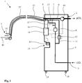
- the filling device 1 shown comprises a filling gun 2, described in more detail below, which is connected to a supply unit 3.
- the supply unit 3 is designed as a mobile cabinet in the embodiment shown in the drawings and has a fixed housing 4.
- a pressure-resistant and thermally insulated supply line 5 for liquid carbon dioxide which is connected to a source of liquid carbon dioxide not shown here, for example a tank, in which the liquid carbon dioxide is stored at a pressure of 20 bar and a temperature of approx. minus 20 ° C, is passed through the housing 4 of the supply unit 3 and opens at a multiple connector 6. Upstream of the multiple connector 6 is an electrical inside the housing 4 controllable control valve 7 arranged.
- phase detector 8 is also provided, which detects the proportions of gas phase and liquid phase of the carbon dioxide flowing through the feed line 5.
- a phase separation device (not shown here) can also be provided in the feed line 5, with which it is ensured that the carbon dioxide fed to the multiple connection 6 contains the greatest possible proportion of liquid phase.
- a discharge line 9 for gaseous carbon dioxide opens out at the multiple connection 6.
- the discharge line 9 is connected in a manner not shown here either to a device for reprocessing or to an exhaust air line leading into the open air.
- Discharge line 9 and supply line 5 can be thermally connected to one another via a heat exchanger, not shown here, by means of which the liquid passed through supply line 5 Carbon dioxide can be pre-cooled with the carbon dioxide gas passed through the discharge line 9.
- a branch line 11 branches off from the supply line 5, in which an evaporator 12 for evaporating liquid carbon dioxide and a control valve 13 are arranged.
- Branch line 11, evaporator 12 and control valve 13 are arranged inside the housing 4 of the supply unit 3.
- a pistol receptacle 14 into which the filling pistol 2 can be inserted in a resting phase before or after a filling process and connected to the housing 4 in a substantially gas-tight manner.
- An electrical heating device 15 for heating the inserted filling pistol 2 is provided in the pistol receptacle 14.
- a photoelectric unit 16 is provided within the housing 4, which is connected to an optical connector on the multiple connector 6 via two optical waveguides 17 (only one of which is shown here).
- the photoelectric unit 16 is integrated in a control and monitoring unit 18 with which the control valves 7, 13, the phase detector 8, the suction pump 10, the heating devices 15 and the evaporator 12 are also in data connection.
- the control and monitoring unit 18 is used to control the filling process in the manner described in more detail below.
- the supply unit is equipped with wheels 19 which are intended to facilitate transport of the supply unit 3 within the location; During normal operation, however, the supply unit 3 is fixed and is basically not moved during a filling process. Instead of the mobile form shown here, however, the supply unit can also be permanently installed at the location.
- the refrigerant receiving compartment 20 of a cooling container 21, which is equipped with walls 22 with good thermal insulation, comprises a cooling container 21 which is shown here only as a section Product receiving compartment 23 or several compartments for receiving products to be cooled as well as an insert 24 for inserting the refrigerant receiving compartment 20, which is designed as a drawer in the exemplary embodiment.
- a door opening 25 is provided on the front of the cooling container 21, which provides access to the product receiving compartment 23 and the refrigerant receiving compartment 20 and which can be closed with a door, not shown here.
- the refrigerant receiving compartment 20 has on its front side 26 two filling openings 28, 29, each equipped with a sealing ring 27, for liquid carbon dioxide and a gas outlet opening 30 for gaseous carbon dioxide.
- the filling openings 28, 29 are arranged horizontally next to one another at a distance of 5 to 10 cm.
- the gas outlet opening 30 is arranged above the filling openings 28, 29, for example 1 to 4 cm apart from them.
- a (lower) snow storage compartment 31 and an (upper) gas vent compartment 32 extend inside the refrigerant receiving compartment 20, which are separated from one another by a gas-permeable filter 33 in such a way that the gas outlet opening 30 into the gas vent compartment 32 and the filling openings 28, 29 into the snow receiving compartment 31 joins.
- the filter 33 preferably extends over the entire width of the refrigerant receiving compartment 20 in order to create the largest possible area for the passage of carbon dioxide gas when the device 1 is in operation.
- two reflectors 24, 35 are arranged in the immediate vicinity of the filling openings 28, 29 and the gas outlet opening 30.
- the reflectors 34, 35 are, for example, an area colored in a specific color.
- a ferromagnetic element for example an iron sheet 36, is arranged.
- the filling pistol 2 comprises a housing 37 made of a light, but low-temperature-resistant material, for example plastic, a light metal or a composite material, which has an orifice 38 and a connection opening 39.
- the mouth opening 38 which is equipped with a circumferential sealing element 40, for example a sealing lip made of a flexible, but low-temperature-resistant material, is dimensioned such that when the filling gun 2 is connected to the refrigerant receptacle 23, both the filling openings 28, 29 and the gas outlet opening 29 of the refrigerant receiving compartment 20 are covered.
- connection opening 39 of the housing 37 is used for gas-tight connection of a flexible gas discharge line 41, which in turn is connected to the multiple connection 6 of the supply unit 3 in a gas-tight, but detachable manner.
- the gas discharge line 41 is, for example, a corrugated hose made of a material that is resistant to low temperatures.
- a handle 42 is arranged on the housing 37.
- the filling gun 2 furthermore comprises an expansion nozzle 45 for supplying liquid carbon dioxide.
- the expansion nozzle 45 is equipped with two nozzle heads 46, 47 which protrude from a T-shaped front section 48 of the expansion nozzle 45 parallel to one another at a distance from one another which corresponds to the distance between the two filling openings 28, 29. This distance is between 5 cm and 10 cm, for example.
- the nozzle heads 46, 47 are each equipped with a nozzle opening 49, 50 which are inclined at an angle of between 0 and 30 ° with respect to the connecting axis of the two nozzle openings 49, 50 in the direction of the front section 48. In Fig. 3 a slight such inclination is indicated by dash-dotted lines at 49, 50.
- the nozzle heads 46, 47 are each pushed into the filling openings 28, 29 and protrude inside the snow receiving compartment 31 in such a way that the nozzle openings 49, 50 are each spaced 5 cm to 10 cm from the inner wall of the front side 26 .
- the expansion nozzle 45 is connected to a flexible and pressure-resistant carbon dioxide liquid supply line 52, which is routed within the gas discharge line 41 and is flow-connected to the supply line 5 at the multiple connector 6.
- the carbon dioxide liquid feed line 52 is accommodated within the gas discharge line 41 and establishes a flow connection to the feed line 5 at the multiple connection 6.
- the multiple connection 6 comprises, for example, a connection piece to which the gas discharge line 41 is firmly but detachably connected.
- a CO 2 liquid connection which is connected to the feed line 5 and to which the carbon dioxide liquid feed line is fixedly but also detachably fastened, is arranged within this connection piece.
- the filling pistol 2 is equipped with one or more, in the exemplary embodiment with two, optical waveguides 54, 55, which each end within the mouth opening 38 of the housing 37 with a conductor head 56, 57.
- the optical waveguides 54, 55 are passed through the housing 37 and the gas discharge line 41 and are optically connected to a respective optical waveguide 17 at a connection terminal arranged in the multiple connector 6.
- the optical waveguides 54, 55, 17 are constructed in a manner known per se and each have an optical fiber for emitted light and an optical waveguide for reflected light, the corresponding light-emitting and light-receiving units being arranged in the photoelectric unit 16.
- a permanent magnet 58 is mounted on the housing 37 within the mouth opening 27 in such a way that it interacts with the sheet iron 36 when the filling pistol is placed on the refrigerant receiving compartment 20.
- the device 1 has two operating modes, a sleep mode and a filling mode.
- the filling pistol 2 is received in the pistol receptacle 14 of the supply unit 3, the sealing element 40 producing an at least largely airtight connection.
- the control valves 7, 13 are closed.
- the suction pump 10 ensures a moderate negative pressure controlled by the control and monitoring unit 18, which is sufficient to hold the filling pistol 2 in the pistol receptacle 14, but which can easily be overcome manually in order to remove the filling pistol 2 from the pistol receptacle 14.
- a ferromagnetic element (not shown here) can also be arranged inside the pistol receptacle 14, which cooperates with the permanent magnet 58 when the filling pistol 2 is pushed in. If the expansion nozzle 45 has a low temperature due to a previous use, it is heated by means of the heating device 15 in order to prevent the accumulation of water on the surface of the expansion nozzle 45.
- the filling pistol 2 is first removed from the pistol receptacle 14 and placed on the front 26 of the refrigerant receiving compartment 20 in such a way that the nozzle heads 46, 47 are inserted into the respective filling openings 28, 29 and the Muzzle opening 38 of the filling gun 2 covers the gas outlet opening 30.
- the sealing element 40 ensures a gas-tight connection between the filling pistol 2 and the front side 26 of the refrigerant receptacle 20.
- the action of the suction pump 10 generates a negative pressure inside the refrigerant receptacle 20 and thus also inside the housing 37 of the filling pistol 2 , which is sufficient to hold the filling gun 2 on the refrigerant receiving compartment 20.
- a magnetic connection between permanent magnet 58 and sheet iron 36 provides additional security.
- optical signals are passed from an emitter of the photoelectric unit 16 through the optical waveguides 17, 54, which are reflected on the reflector 34.
- the reflected optical signals pass through the optical waveguides 54, 17 back to a detector of the photoelectric unit 16, where they are recorded and evaluated in the control and monitoring unit 18. If the control and monitoring unit 18 recognizes a correct position of the filling gun, the control valves 7, 13 are released for manual actuation.
- the optical waveguide 55 is used to determine the respective type of the refrigerant receiving compartment 20.
- the reflector 35 is designed specifically for a certain type of refrigerant receiving compartments 20 and has type-specific reflection properties which lead accordingly to different reflection signals transmitted to the control and monitoring unit 18. From this, the control and monitoring unit 18 determines the type of refrigerant receiving compartment and initiates a filling procedure corresponding to the type of refrigerant receiving compartment 20.
- the filling process is then started on the basis of a command entered manually into the control and monitoring unit 18.
- the carbon dioxide liquid feed line 52 is first flooded with gaseous carbon dioxide by opening the control valve 13 and starting the evaporator 12.
- liquid carbon dioxide is evaporated from the supply line 5 in the evaporator 12 and flows into the carbon dioxide liquid supply line 52.
- the purpose of the flooding is to create a pressure above the triple point pressure of 5.18 in the carbon dioxide liquid feed line 52 to generate bar in order to prevent that liquid carbon dioxide relaxes when entering the carbon dioxide liquid feed line 52 and the carbon dioxide snow generated thereby clogs the carbon dioxide liquid feed line 52.
- control valve 13 is closed and the evaporator 12 is switched off.
- the control valve 7 is then opened and liquid carbon dioxide flows at a pressure of, for example, 10 bar to 20 bar via the supply line 5 and the carbon dioxide liquid supply line 52 to the expansion nozzle 45, where it enters the snow receptacle 31 at the nozzle openings 49, 50.
- the control and monitoring unit 18 regulates, in particular, the supply of liquid carbon dioxide as a function of a gas phase component determined at the phase detector 8 and the suction strength of the suction pump 10 as a function of a pressure determined in the discharge line 9, upstream of the suction pump 10, by means of detectors not shown here .
- the liquid carbon dioxide relaxes and changes into a mixture of carbon dioxide snow and carbon dioxide gas. While the carbon dioxide snow is retained in the snow receiving compartment 31, the carbon dioxide gas produced during the expansion passes through the gas-permeable filter 33 into the gas vent compartment 32 and is drawn off by means of the suction pump 10 via the gas vent line 41 and the discharge line 9.
- the arrangement of the carbon dioxide liquid feed line 52 within the gas discharge line 41 serves to precool the liquid carbon dioxide and thus to increase the efficiency of the filling process.
- the evaporator 12 is switched on and the control valve 13 is opened. The control valve 7 is then closed.
- carbon dioxide gas flows into the carbon dioxide liquid feed line 52 and prevents liquid carbon dioxide still present in the carbon dioxide feed line 52 from being expanded with the formation of carbon dioxide snow and from clogging the carbon dioxide feed line 52.
- the control valve 13 is closed.
- the filling pistol 2 does not have any electrical components in its interior and, in particular, has a very low weight of, for example, less than 1 kg. Due to the low weight, the negative pressure generated by the suction pump 10 in the refrigerant receiving compartment 20 is generally sufficient to hold the filling pistol 2 on the refrigerant receiving compartment 20 during the filling.
- the light construction of the filling pistol 2 also makes it possible to dispense with complex crane arrangements for holding the filling pistol during the filling procedure.
- the filling gun 2 is moved and operated manually by an operator using the handle 42.
- the flexible parts of the gas discharge line 41 or the carbon dioxide liquid feed line 52 or the optical waveguides 54, 55 are sometimes subjected to severe stress due to bending and twisting.
- the gas discharge line 41, the carbon dioxide liquid feed line 52 and the optical waveguide 54, 55 on the multiple connector 6 and / or in the area of the connection opening 39 are each provided with one opposite the terminating nozzle 6 or the filling gun 2 rotatably or pivotably mounted connection piece (not shown here) equipped.
- the filling pistol 2a shown differs from the filling pistol 20 only in that it has a different expansion nozzle 45a. Otherwise, the same features are denoted by the same reference numerals as in the case of the filling gun 2.
- the expansion nozzle 45a has two nozzle heads 46a, 47a, which are arranged at a smaller distance from one another than the nozzle heads 46, 47 of the Relaxation nozzle 45. For example, the distance between the two nozzle heads 46a, 47a is 1 cm to 3 cm. In the case of the filling pistol 2a, too, the nozzle heads 46a, 47a are equipped with nozzle openings 49a, 50a directed towards one another.
- the filling pistol 20a is used to fill a refrigerant receiving compartment 20a, in the snow receiving compartment 31a of which there is only one filling opening 28a, into which the two nozzle heads 46a, 47a are jointly inserted for the purpose of filling the refrigerant receiving compartment 20a.
- a permanent magnet is present, which cooperates to establish a secure connection with a ferromagnetic element, likewise not shown, in the front side 26 of the refrigerant receiving compartment 20a.
- the filling pistol 20a between the nozzle heads 46a, 47a is parallel to the orifice 38a of the filling pistol 20a a retaining plate 59 is arranged which, during filling, seals off the parts of the filling opening 28a which are not filled by the nozzle heads 46a, 47a.
- Fig. 5 shows the jet pattern of the expansion nozzle 45a Fig. 4 in the by the line VV in Fig. 4 marked plane perpendicular to the longitudinal extent of the expansion nozzle 45a.
- the nozzle openings 49a, 50a of the respective nozzle heads 46a, 47a are directed towards one another, so that the two carbon dioxide jets 60, 61 exiting from the nozzle openings 49a, 50a and expanding in a fan-like manner collide with one another.
- the pulse currents of the two carbon dioxide jets 60, 61 cancel each other out, at least to a significant extent; in particular, there is no or only a slight force component which forces the expansion nozzle 45a out of the filling opening 28a.
- a turbulent flow is generated within the snow storage compartment 31a, due to which the dry ice particles generated during the expansion of the carbon dioxide are distributed very evenly in the snow storage compartment.
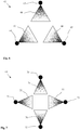
- the embodiment according to Fig. 6 shows an expansion nozzle 62 with three parallel nozzle heads 63, 64, 65 which - seen in cross section - are arranged in the form of an equilateral triangle.
- the nozzle heads 63, 64, 65 each have similar nozzle openings, which are each arranged at the same height on the nozzle heads 63, 64, 65 in such a way that the impulse flows of the carbon dioxide jets 66, 67, 68 flowing out of them cancel each other out.
- the nozzle opening of a nozzle head 63, 64, 65 points in each case to the center of the connecting line of the two remaining nozzle heads 64, 65, 63.
- FIG. 7 shows an expansion nozzle 69 with four parallel nozzle heads 70, 71, 72, 73 which - seen in cross section - are arranged in the form of a square.
- the nozzle heads 70, 71, 72, 73 each have similar nozzle openings, which are each arranged at the same height on the nozzle heads 70, 71, 72, 73 in such a way that the impulse flows of the carbon dioxide jets 74, 75, 76, 77 flowing out of them are mutually exclusive cancel.
- the nozzle openings each have opposing nozzle heads 70-72; 71-73 towards each other.
- expansion nozzles 62, 69 each correspond to corresponding filling openings of a refrigerant receiving compartment to be filled, whereby, similarly to the FIGS FIGS. 2 and 3 exemplary embodiments shown, each with separate filling openings for each nozzle head 63, 64, 65; 70, 71, 72, 73, or a common filling opening for all nozzle heads 63, 64, 65; 70, 71, 72, 73 of a relaxation nozzle 62, 69 can be provided.
- the preferred number of nozzle heads and / or nozzle openings depends in particular on the geometry of the refrigerant receiving compartment to be filled and the amount of carbon dioxide snow to be supplied. In any case, when designing the expansion nozzle, care should be taken to ensure that when the refrigerant receiving compartment is filled, the impulse flows of the carbon dioxide jets emerging from the nozzle openings at least substantially cancel each other out and that no or at least only a negligible resulting force effect in the axial direction occurs due to the emerging carbon dioxide jets that propel the expansion nozzle out of the filling opening or openings could.
- the embodiment according to the invention also discloses a
Landscapes
- Engineering & Computer Science (AREA)
- Chemical & Material Sciences (AREA)
- Chemical Kinetics & Catalysis (AREA)
- Combustion & Propulsion (AREA)
- Physics & Mathematics (AREA)
- Mechanical Engineering (AREA)
- Thermal Sciences (AREA)
- General Engineering & Computer Science (AREA)
- Filling Or Discharging Of Gas Storage Vessels (AREA)
- Carbon And Carbon Compounds (AREA)
Priority Applications (1)
| Application Number | Priority Date | Filing Date | Title |
|---|---|---|---|
| PL16742299T PL3325901T3 (pl) | 2015-07-24 | 2016-07-22 | Urządzenie napełniające do napełniania komory przyjmującej czynnik chłodniczy przyporządkowanej do pojemnika chłodniczego kriogenicznym czynnikiem chłodniczym |
Applications Claiming Priority (2)
| Application Number | Priority Date | Filing Date | Title |
|---|---|---|---|
| DE102015009647.8A DE102015009647B3 (de) | 2015-07-24 | 2015-07-24 | Füllvorrichtung zum Befüllen eines einem Kühlbehälter zugeordneten Kältemittel-Aufnahmefachs mit einem kryogenen Kältemittel |
| PCT/EP2016/067574 WO2017017030A1 (de) | 2015-07-24 | 2016-07-22 | Füllvorrichtung zum befüllen eines einem kühlbehälter zugeordneten kältemittel-aufnahmefachs mit einem kryogenen kältemittel |
Publications (2)
| Publication Number | Publication Date |
|---|---|
| EP3325901A1 EP3325901A1 (de) | 2018-05-30 |
| EP3325901B1 true EP3325901B1 (de) | 2021-03-10 |
Family
ID=56550230
Family Applications (1)
| Application Number | Title | Priority Date | Filing Date |
|---|---|---|---|
| EP16742299.7A Active EP3325901B1 (de) | 2015-07-24 | 2016-07-22 | Füllvorrichtung zum befüllen eines einem kühlbehälter zugeordneten kältemittel-aufnahmefachs mit einem kryogenen kältemittel |
Country Status (7)
| Country | Link |
|---|---|
| EP (1) | EP3325901B1 (pl) |
| CN (1) | CN107923686B (pl) |
| DE (1) | DE102015009647B3 (pl) |
| ES (1) | ES2866033T3 (pl) |
| HU (1) | HUE054077T2 (pl) |
| PL (1) | PL3325901T3 (pl) |
| WO (1) | WO2017017030A1 (pl) |
Families Citing this family (1)
| Publication number | Priority date | Publication date | Assignee | Title |
|---|---|---|---|---|
| DE102020002206A1 (de) * | 2020-04-08 | 2021-10-14 | Messer France S.A.S. | Vorrichtung zum Erzeugen und Speichern von Kohlendioxidschnee |
Family Cites Families (18)
| Publication number | Priority date | Publication date | Assignee | Title |
|---|---|---|---|---|
| GB775371A (en) * | 1953-07-20 | 1957-05-22 | Herbert William Brock | An improved method of and means for, coating plastic materials |
| US4640460A (en) * | 1985-02-19 | 1987-02-03 | Franklin Jr Paul R | CO2 snow forming header with triple point feature |
| CN87212367U (zh) * | 1987-10-13 | 1988-09-21 | 邵伟强 | 便携式自冷保鲜箱 |
| GB8815584D0 (en) * | 1988-06-30 | 1988-08-03 | Analytical Instr Ltd | Fleet data monitoring system |
| US5398522A (en) * | 1994-04-28 | 1995-03-21 | Franklin, Jr.; Paul R. | Double end servicing freight container CO2 snow forming header |
| DE69510025T2 (de) * | 1994-12-15 | 1999-12-09 | He Holdings Inc., Los Angeles | CO2-Sprühdüse mit Mehrfachöffnung |
| US5638688A (en) * | 1995-11-24 | 1997-06-17 | Reznikov; Lev | Method of and apparatus for cooling food products |
| US6761043B1 (en) * | 1997-06-16 | 2004-07-13 | Lev Reznikov | Apparatus for cooling food products |
| DE19808267A1 (de) * | 1998-02-27 | 1999-09-02 | Messer France Sa | Befüll- und Entnahmemodul für ein Kühlmodul und Verfahren zum Befüllen eines Kühlmoduls |
| FR2776056B1 (fr) * | 1998-03-10 | 2000-05-26 | Olivo | Dispositif brise-jet pour compartiment cryogenique de conteneur isothermique |
| DE102005033854B4 (de) * | 2005-07-12 | 2007-06-14 | Siemens Ag | Anordnung mit einem Tankeinlass und einer Tankbefülleinrichtung und Verfahren zu deren Betrieb |
| FR2891354B1 (fr) * | 2005-09-28 | 2007-11-16 | Air Liquide | Receptacle de neige carbonique a double compartiment pour conteneurs isothermes |
| FR2891899B1 (fr) * | 2005-10-12 | 2007-11-30 | Air Liquide | Systeme d'injection de neige carbonique dans des conteneurs isothermes et conteneurs associes |
| EP2336684B1 (de) * | 2009-12-21 | 2013-04-03 | Messer France S.A.S. | Befüllvorrichtung zum Befüllen eines einem Kühlbehälter zugeordneten Kältemittel-Aufnahmefachs mit einem kryogenen Kältemittel |
| NL1039372C2 (nl) * | 2011-02-09 | 2013-12-30 | Acp Polska Spolka Z Ograniczona Odpowiedzialnoscia | Systeem voor het inbrengen van koelmiddel in een container. |
| DE102011014943A1 (de) * | 2011-03-24 | 2012-09-27 | Airbus Operations Gmbh | Multifunktionaler Kälteträgermediumbehälter und Verfahren zum Betreiben eines derartigen Kälteträgermediumbehälters |
| DE102011121013A1 (de) * | 2011-12-13 | 2013-06-13 | Linde Aktiengesellschaft | Vorrichtung und Verfahren zurTemperaturhaltung |
| DE102012006478A1 (de) * | 2012-03-29 | 2013-10-02 | Linde Aktiengesellschaft | Kühlmittelbehälter, Vorrichtung und Verfahren zur Temperaturhaltung |
-
2015
- 2015-07-24 DE DE102015009647.8A patent/DE102015009647B3/de not_active Expired - Fee Related
-
2016
- 2016-07-22 WO PCT/EP2016/067574 patent/WO2017017030A1/de not_active Ceased
- 2016-07-22 ES ES16742299T patent/ES2866033T3/es active Active
- 2016-07-22 EP EP16742299.7A patent/EP3325901B1/de active Active
- 2016-07-22 HU HUE16742299A patent/HUE054077T2/hu unknown
- 2016-07-22 CN CN201680042244.3A patent/CN107923686B/zh active Active
- 2016-07-22 PL PL16742299T patent/PL3325901T3/pl unknown
Non-Patent Citations (1)
| Title |
|---|
| None * |
Also Published As
| Publication number | Publication date |
|---|---|
| HUE054077T2 (hu) | 2021-08-30 |
| EP3325901A1 (de) | 2018-05-30 |
| ES2866033T3 (es) | 2021-10-19 |
| CN107923686B (zh) | 2020-11-10 |
| PL3325901T3 (pl) | 2021-07-26 |
| WO2017017030A1 (de) | 2017-02-02 |
| CN107923686A (zh) | 2018-04-17 |
| DE102015009647B3 (de) | 2016-10-06 |
Similar Documents
| Publication | Publication Date | Title |
|---|---|---|
| EP3325900B1 (de) | Füllvorrichtung zum befüllen eines einem kühlbehälter zugeordneten kältemittel-aufnahmefachs mit einem kryogenen kältemittel | |
| DE3234268C2 (pl) | ||
| DE60113738T2 (de) | Gerät zum Kühlen und Gefrieren von Waren | |
| DE60317467T2 (de) | Verfahren zum kühlen einer vorrichtung zum isostatischen heisspressen und vorrichtung zum isostatischen heisspressen | |
| DE60006212T2 (de) | Apparat zur gasbehandlung von produkten | |
| DE19500487A1 (de) | Einrichtung zum Entfernen von Kühlluft | |
| EP2336684B1 (de) | Befüllvorrichtung zum Befüllen eines einem Kühlbehälter zugeordneten Kältemittel-Aufnahmefachs mit einem kryogenen Kältemittel | |
| EP2874879A1 (de) | Kühlkonzept kaltluftdusche | |
| EP0077960B2 (de) | Kühlgutbehälter zum Kühlen eines Kühlgutes in einem Behälter | |
| DE10303736B4 (de) | Klimaschrank und insbesondere Klimakühlschrank | |
| EP3325901B1 (de) | Füllvorrichtung zum befüllen eines einem kühlbehälter zugeordneten kältemittel-aufnahmefachs mit einem kryogenen kältemittel | |
| DE102012002403A9 (de) | System zur Einführung eines Kühlmittels in einen Container | |
| DE102004018133B3 (de) | Anordnung zur Erzeugung eines Trockeneispartikel-Strahls sowie deren Verwendung | |
| DE20104205U1 (de) | Heißlufttrockner für eine Beschichtungsanlage | |
| DE3026530A1 (de) | Kopfseitig offener, gekuehlter schaustellbehaelter mit mit umgebender luft arbeitendem abtausystem | |
| EP4013719A1 (de) | Vorrichtung zum dosieren von kohlendioxidschnee | |
| DE3027397A1 (de) | Kuehlraum | |
| DE102018118472B4 (de) | Mobile Kühlvorrichtung | |
| DE8521012U1 (de) | Vorrichtung zum Temperieren von elektronischen Einrichtungen in geschlossenen Räumen | |
| DE10304011A1 (de) | Klimavorrichtung und Verfahren zum Abtauen eines Wärmeaustauschers einer Klimavorrichtung | |
| DE60315222T2 (de) | Tiefgefrieranlage, insbesondere für Lebensmittel, mit hocheffizientem Wärmeausstausch zwischen dem kryogenen Gas und dem Gefriergut | |
| DE102009011732A1 (de) | Verfahren und Vorrichtung zum Kühlen von Speisen in einem mehretagigen Transportwagen | |
| EP1242775A1 (de) | Kältegerät wie no-frost-kühl- oder gefrierschrank | |
| DE2903144C2 (de) | Vorrichtung zum gekühlten Aufbahren eingesargter Leichen | |
| DE10066504B3 (de) | Luftführungseinrichtung für Kühl- oder Warmluft in zu klimatisierenden Räumen zur Aufnahme zu klimatisierender Güter und zu klimatisierender Raum |
Legal Events
| Date | Code | Title | Description |
|---|---|---|---|
| STAA | Information on the status of an ep patent application or granted ep patent |
Free format text: STATUS: THE INTERNATIONAL PUBLICATION HAS BEEN MADE |
|
| PUAI | Public reference made under article 153(3) epc to a published international application that has entered the european phase |
Free format text: ORIGINAL CODE: 0009012 |
|
| STAA | Information on the status of an ep patent application or granted ep patent |
Free format text: STATUS: REQUEST FOR EXAMINATION WAS MADE |
|
| 17P | Request for examination filed |
Effective date: 20180226 |
|
| AK | Designated contracting states |
Kind code of ref document: A1 Designated state(s): AL AT BE BG CH CY CZ DE DK EE ES FI FR GB GR HR HU IE IS IT LI LT LU LV MC MK MT NL NO PL PT RO RS SE SI SK SM TR |
|
| AX | Request for extension of the european patent |
Extension state: BA ME |
|
| STAA | Information on the status of an ep patent application or granted ep patent |
Free format text: STATUS: EXAMINATION IS IN PROGRESS |
|
| 17Q | First examination report despatched |
Effective date: 20200211 |
|
| GRAP | Despatch of communication of intention to grant a patent |
Free format text: ORIGINAL CODE: EPIDOSNIGR1 |
|
| STAA | Information on the status of an ep patent application or granted ep patent |
Free format text: STATUS: GRANT OF PATENT IS INTENDED |
|
| INTG | Intention to grant announced |
Effective date: 20201124 |
|
| GRAS | Grant fee paid |
Free format text: ORIGINAL CODE: EPIDOSNIGR3 |
|
| GRAA | (expected) grant |
Free format text: ORIGINAL CODE: 0009210 |
|
| STAA | Information on the status of an ep patent application or granted ep patent |
Free format text: STATUS: THE PATENT HAS BEEN GRANTED |
|
| AK | Designated contracting states |
Kind code of ref document: B1 Designated state(s): AL AT BE BG CH CY CZ DE DK EE ES FI FR GB GR HR HU IE IS IT LI LT LU LV MC MK MT NL NO PL PT RO RS SE SI SK SM TR |
|
| AX | Request for extension of the european patent |
Extension state: BA ME |
|
| REG | Reference to a national code |
Ref country code: GB Ref legal event code: FG4D Free format text: NOT ENGLISH |
|
| REG | Reference to a national code |
Ref country code: AT Ref legal event code: REF Ref document number: 1370251 Country of ref document: AT Kind code of ref document: T Effective date: 20210315 Ref country code: CH Ref legal event code: EP |
|
| REG | Reference to a national code |
Ref country code: IE Ref legal event code: FG4D Free format text: LANGUAGE OF EP DOCUMENT: GERMAN |
|
| REG | Reference to a national code |
Ref country code: DE Ref legal event code: R096 Ref document number: 502016012562 Country of ref document: DE |
|
| REG | Reference to a national code |
Ref country code: RO Ref legal event code: EPE |
|
| REG | Reference to a national code |
Ref country code: LT Ref legal event code: MG9D |
|
| PG25 | Lapsed in a contracting state [announced via postgrant information from national office to epo] |
Ref country code: NO Free format text: LAPSE BECAUSE OF FAILURE TO SUBMIT A TRANSLATION OF THE DESCRIPTION OR TO PAY THE FEE WITHIN THE PRESCRIBED TIME-LIMIT Effective date: 20210610 Ref country code: FI Free format text: LAPSE BECAUSE OF FAILURE TO SUBMIT A TRANSLATION OF THE DESCRIPTION OR TO PAY THE FEE WITHIN THE PRESCRIBED TIME-LIMIT Effective date: 20210310 Ref country code: GR Free format text: LAPSE BECAUSE OF FAILURE TO SUBMIT A TRANSLATION OF THE DESCRIPTION OR TO PAY THE FEE WITHIN THE PRESCRIBED TIME-LIMIT Effective date: 20210611 Ref country code: HR Free format text: LAPSE BECAUSE OF FAILURE TO SUBMIT A TRANSLATION OF THE DESCRIPTION OR TO PAY THE FEE WITHIN THE PRESCRIBED TIME-LIMIT Effective date: 20210310 Ref country code: LT Free format text: LAPSE BECAUSE OF FAILURE TO SUBMIT A TRANSLATION OF THE DESCRIPTION OR TO PAY THE FEE WITHIN THE PRESCRIBED TIME-LIMIT Effective date: 20210310 Ref country code: BG Free format text: LAPSE BECAUSE OF FAILURE TO SUBMIT A TRANSLATION OF THE DESCRIPTION OR TO PAY THE FEE WITHIN THE PRESCRIBED TIME-LIMIT Effective date: 20210610 |
|
| REG | Reference to a national code |
Ref country code: NL Ref legal event code: MP Effective date: 20210310 |
|
| REG | Reference to a national code |
Ref country code: HU Ref legal event code: AG4A Ref document number: E054077 Country of ref document: HU |
|
| PG25 | Lapsed in a contracting state [announced via postgrant information from national office to epo] |
Ref country code: SE Free format text: LAPSE BECAUSE OF FAILURE TO SUBMIT A TRANSLATION OF THE DESCRIPTION OR TO PAY THE FEE WITHIN THE PRESCRIBED TIME-LIMIT Effective date: 20210310 Ref country code: LV Free format text: LAPSE BECAUSE OF FAILURE TO SUBMIT A TRANSLATION OF THE DESCRIPTION OR TO PAY THE FEE WITHIN THE PRESCRIBED TIME-LIMIT Effective date: 20210310 Ref country code: RS Free format text: LAPSE BECAUSE OF FAILURE TO SUBMIT A TRANSLATION OF THE DESCRIPTION OR TO PAY THE FEE WITHIN THE PRESCRIBED TIME-LIMIT Effective date: 20210310 |
|
| PG25 | Lapsed in a contracting state [announced via postgrant information from national office to epo] |
Ref country code: NL Free format text: LAPSE BECAUSE OF FAILURE TO SUBMIT A TRANSLATION OF THE DESCRIPTION OR TO PAY THE FEE WITHIN THE PRESCRIBED TIME-LIMIT Effective date: 20210310 |
|
| REG | Reference to a national code |
Ref country code: ES Ref legal event code: FG2A Ref document number: 2866033 Country of ref document: ES Kind code of ref document: T3 Effective date: 20211019 |
|
| PG25 | Lapsed in a contracting state [announced via postgrant information from national office to epo] |
Ref country code: CZ Free format text: LAPSE BECAUSE OF FAILURE TO SUBMIT A TRANSLATION OF THE DESCRIPTION OR TO PAY THE FEE WITHIN THE PRESCRIBED TIME-LIMIT Effective date: 20210310 Ref country code: EE Free format text: LAPSE BECAUSE OF FAILURE TO SUBMIT A TRANSLATION OF THE DESCRIPTION OR TO PAY THE FEE WITHIN THE PRESCRIBED TIME-LIMIT Effective date: 20210310 Ref country code: SM Free format text: LAPSE BECAUSE OF FAILURE TO SUBMIT A TRANSLATION OF THE DESCRIPTION OR TO PAY THE FEE WITHIN THE PRESCRIBED TIME-LIMIT Effective date: 20210310 |
|
| PG25 | Lapsed in a contracting state [announced via postgrant information from national office to epo] |
Ref country code: PT Free format text: LAPSE BECAUSE OF FAILURE TO SUBMIT A TRANSLATION OF THE DESCRIPTION OR TO PAY THE FEE WITHIN THE PRESCRIBED TIME-LIMIT Effective date: 20210712 Ref country code: SK Free format text: LAPSE BECAUSE OF FAILURE TO SUBMIT A TRANSLATION OF THE DESCRIPTION OR TO PAY THE FEE WITHIN THE PRESCRIBED TIME-LIMIT Effective date: 20210310 Ref country code: IS Free format text: LAPSE BECAUSE OF FAILURE TO SUBMIT A TRANSLATION OF THE DESCRIPTION OR TO PAY THE FEE WITHIN THE PRESCRIBED TIME-LIMIT Effective date: 20210710 |
|
| VS25 | Lapsed in a validation state [announced via postgrant information from nat. office to epo] |
Ref country code: MD Free format text: LAPSE BECAUSE OF FAILURE TO SUBMIT A TRANSLATION OF THE DESCRIPTION OR TO PAY THE FEE WITHIN THE PRESCRIBED TIME-LIMIT Effective date: 20210310 |
|
| REG | Reference to a national code |
Ref country code: DE Ref legal event code: R097 Ref document number: 502016012562 Country of ref document: DE |
|
| PLBE | No opposition filed within time limit |
Free format text: ORIGINAL CODE: 0009261 |
|
| STAA | Information on the status of an ep patent application or granted ep patent |
Free format text: STATUS: NO OPPOSITION FILED WITHIN TIME LIMIT |
|
| PG25 | Lapsed in a contracting state [announced via postgrant information from national office to epo] |
Ref country code: AL Free format text: LAPSE BECAUSE OF FAILURE TO SUBMIT A TRANSLATION OF THE DESCRIPTION OR TO PAY THE FEE WITHIN THE PRESCRIBED TIME-LIMIT Effective date: 20210310 Ref country code: DK Free format text: LAPSE BECAUSE OF FAILURE TO SUBMIT A TRANSLATION OF THE DESCRIPTION OR TO PAY THE FEE WITHIN THE PRESCRIBED TIME-LIMIT Effective date: 20210310 |
|
| 26N | No opposition filed |
Effective date: 20211213 |
|
| PG25 | Lapsed in a contracting state [announced via postgrant information from national office to epo] |
Ref country code: SI Free format text: LAPSE BECAUSE OF FAILURE TO SUBMIT A TRANSLATION OF THE DESCRIPTION OR TO PAY THE FEE WITHIN THE PRESCRIBED TIME-LIMIT Effective date: 20210310 |
|
| REG | Reference to a national code |
Ref country code: CH Ref legal event code: PL |
|
| GBPC | Gb: european patent ceased through non-payment of renewal fee |
Effective date: 20210722 |
|
| PG25 | Lapsed in a contracting state [announced via postgrant information from national office to epo] |
Ref country code: MC Free format text: LAPSE BECAUSE OF FAILURE TO SUBMIT A TRANSLATION OF THE DESCRIPTION OR TO PAY THE FEE WITHIN THE PRESCRIBED TIME-LIMIT Effective date: 20210310 |
|
| PG25 | Lapsed in a contracting state [announced via postgrant information from national office to epo] |
Ref country code: LI Free format text: LAPSE BECAUSE OF NON-PAYMENT OF DUE FEES Effective date: 20210731 Ref country code: IT Free format text: LAPSE BECAUSE OF FAILURE TO SUBMIT A TRANSLATION OF THE DESCRIPTION OR TO PAY THE FEE WITHIN THE PRESCRIBED TIME-LIMIT Effective date: 20210310 Ref country code: GB Free format text: LAPSE BECAUSE OF NON-PAYMENT OF DUE FEES Effective date: 20210722 Ref country code: CH Free format text: LAPSE BECAUSE OF NON-PAYMENT OF DUE FEES Effective date: 20210731 |
|
| PG25 | Lapsed in a contracting state [announced via postgrant information from national office to epo] |
Ref country code: IS Free format text: LAPSE BECAUSE OF FAILURE TO SUBMIT A TRANSLATION OF THE DESCRIPTION OR TO PAY THE FEE WITHIN THE PRESCRIBED TIME-LIMIT Effective date: 20210710 Ref country code: LU Free format text: LAPSE BECAUSE OF NON-PAYMENT OF DUE FEES Effective date: 20210722 |
|
| PG25 | Lapsed in a contracting state [announced via postgrant information from national office to epo] |
Ref country code: IE Free format text: LAPSE BECAUSE OF NON-PAYMENT OF DUE FEES Effective date: 20210722 |
|
| PG25 | Lapsed in a contracting state [announced via postgrant information from national office to epo] |
Ref country code: CY Free format text: LAPSE BECAUSE OF FAILURE TO SUBMIT A TRANSLATION OF THE DESCRIPTION OR TO PAY THE FEE WITHIN THE PRESCRIBED TIME-LIMIT Effective date: 20210310 |
|
| PG25 | Lapsed in a contracting state [announced via postgrant information from national office to epo] |
Ref country code: MK Free format text: LAPSE BECAUSE OF FAILURE TO SUBMIT A TRANSLATION OF THE DESCRIPTION OR TO PAY THE FEE WITHIN THE PRESCRIBED TIME-LIMIT Effective date: 20210310 |
|
| VS25 | Lapsed in a validation state [announced via postgrant information from nat. office to epo] |
Ref country code: MA Free format text: LAPSE BECAUSE OF FAILURE TO SUBMIT A TRANSLATION OF THE DESCRIPTION OR TO PAY THE FEE WITHIN THE PRESCRIBED TIME-LIMIT Effective date: 20210310 |
|
| PG25 | Lapsed in a contracting state [announced via postgrant information from national office to epo] |
Ref country code: MT Free format text: LAPSE BECAUSE OF FAILURE TO SUBMIT A TRANSLATION OF THE DESCRIPTION OR TO PAY THE FEE WITHIN THE PRESCRIBED TIME-LIMIT Effective date: 20210310 |
|
| PGFP | Annual fee paid to national office [announced via postgrant information from national office to epo] |
Ref country code: PL Payment date: 20250612 Year of fee payment: 10 |
|
| PGFP | Annual fee paid to national office [announced via postgrant information from national office to epo] |
Ref country code: BE Payment date: 20250619 Year of fee payment: 10 |
|
| PGFP | Annual fee paid to national office [announced via postgrant information from national office to epo] |
Ref country code: FR Payment date: 20250610 Year of fee payment: 10 |
|
| PGFP | Annual fee paid to national office [announced via postgrant information from national office to epo] |
Ref country code: RO Payment date: 20250625 Year of fee payment: 10 |
|
| PGFP | Annual fee paid to national office [announced via postgrant information from national office to epo] |
Ref country code: HU Payment date: 20250630 Year of fee payment: 10 |
|
| PGFP | Annual fee paid to national office [announced via postgrant information from national office to epo] |
Ref country code: ES Payment date: 20250804 Year of fee payment: 10 |
|
| PGFP | Annual fee paid to national office [announced via postgrant information from national office to epo] |
Ref country code: DE Payment date: 20250731 Year of fee payment: 10 |
|
| PGFP | Annual fee paid to national office [announced via postgrant information from national office to epo] |
Ref country code: AT Payment date: 20250625 Year of fee payment: 10 |
|
| PG25 | Lapsed in a contracting state [announced via postgrant information from national office to epo] |
Ref country code: TR Free format text: LAPSE BECAUSE OF FAILURE TO SUBMIT A TRANSLATION OF THE DESCRIPTION OR TO PAY THE FEE WITHIN THE PRESCRIBED TIME-LIMIT Effective date: 20210310 |