EP3325901B1 - Füllvorrichtung zum befüllen eines einem kühlbehälter zugeordneten kältemittel-aufnahmefachs mit einem kryogenen kältemittel - Google Patents
Füllvorrichtung zum befüllen eines einem kühlbehälter zugeordneten kältemittel-aufnahmefachs mit einem kryogenen kältemittel Download PDFInfo
- Publication number
- EP3325901B1 EP3325901B1 EP16742299.7A EP16742299A EP3325901B1 EP 3325901 B1 EP3325901 B1 EP 3325901B1 EP 16742299 A EP16742299 A EP 16742299A EP 3325901 B1 EP3325901 B1 EP 3325901B1
- Authority
- EP
- European Patent Office
- Prior art keywords
- filling
- carbon dioxide
- nozzle
- pistol
- receiving compartment
- Prior art date
- Legal status (The legal status is an assumption and is not a legal conclusion. Google has not performed a legal analysis and makes no representation as to the accuracy of the status listed.)
- Active
Links
Images


Classifications
-
- F—MECHANICAL ENGINEERING; LIGHTING; HEATING; WEAPONS; BLASTING
- F25—REFRIGERATION OR COOLING; COMBINED HEATING AND REFRIGERATION SYSTEMS; HEAT PUMP SYSTEMS; MANUFACTURE OR STORAGE OF ICE; LIQUEFACTION SOLIDIFICATION OF GASES
- F25D—REFRIGERATORS; COLD ROOMS; ICE-BOXES; COOLING OR FREEZING APPARATUS NOT OTHERWISE PROVIDED FOR
- F25D3/00—Devices using other cold materials; Devices using cold-storage bodies
- F25D3/12—Devices using other cold materials; Devices using cold-storage bodies using solidified gases, e.g. carbon-dioxide snow
- F25D3/125—Movable containers
Definitions
- the invention relates to a filling device for filling a refrigerant receiving compartment assigned to a cooling container for cooling products with carbon dioxide snow, with a supply unit and a filling pistol that can be coupled to the supply unit, the filling pistol having an expansion nozzle that can be connected to at least one filling opening of the refrigerant receiving compartment for supplying liquid Has carbon dioxide and a suction opening that can be connected to a gas outlet opening of the refrigerant receiving compartment for discharging gaseous carbon dioxide and is connected to the supply unit via a carbon dioxide liquid feed line that is flow-connected to the filling opening and a suction line that is flow-connected to the suction opening, and with a control valve for regulating the supply of liquid carbon dioxide into the carbon dioxide liquid feed line, a suction device for sucking off gaseous carbon dioxide from the suction line and a control and monitoring unit for Control the filling process.
- Mobile isothermal cooling containers are used to transport heat-sensitive products, in particular food such as fresh or frozen products, with which a seamless cooling chain from production to the end customer is to be ensured even if permanent cooling by an electrically operated cooling device is not possible is.
- Such mobile cooling containers have a product receiving compartment for storing the products to be kept cool and a refrigerant receiving compartment for a cryogenic refrigerant that is spatially separated from this but is thermally connected to it.
- the refrigerant absorbs heat that penetrates through the walls of the container and thus ensures that the temperature in the product receiving compartment does not rise and the product is kept at a low temperature. This leads to gradual evaporation or sublimation of the refrigerant.
- the product can in this way be kept at a certain low temperature for many hours without the need for a permanent external energy supply.
- the cooler of the talk standing type are dimensioned so that they can easily be moved by one person by means of wheels attached to them.
- Typical cooling containers have, for example, a base area based on the European pallet standard of 600 mm x 800 mm to 1200 mm x 800 mm and a height between 1000 mm and 2000 mm and a useful volume of, for example, between 200 liters and 1500 liters.
- the compartment for the refrigerant is much smaller than the compartment for receiving the products and has, for example a volume between 5 liters and 50 liters.
- the present invention relates to a filling device for filling such refrigerant receiving compartments.
- a cooling container of the aforementioned type is for example from EP 0 942 244 A1 known.
- the container has a drawer-like refrigerant receptacle for carbon dioxide snow, which is thermally and fluidically connected to a product receptacle arranged below.
- the refrigerant storage compartment is loaded with carbon dioxide snow with a temperature of -78 ° C, which absorbs heat penetrating into the cooling container and gradually sublimates in the process. Due to a suitable setting of the heat transfer between the compartments, the products can be reliably kept at a temperature of, for example, 0 ° C to 5 ° C (for fresh goods) or -15 ° C to -25 ° C (frozen goods) for more than 24 hours.
- the filling device has a filling pistol and a supply unit connected to it.
- the filling pistol is equipped with an expansion nozzle which is inserted into a filling opening of the refrigerant receiving compartment, as well as with an exhaust device which is connected to a gas exhaust opening of the refrigerant receiving compartment.
- liquid carbon dioxide is supplied which, when exiting the expansion nozzle, expands with strong cooling, a mixture of carbon dioxide snow and carbon dioxide gas being formed.
- the filling pistol is equipped with connection fittings with which the filling pistol is connected to the refrigerant receiving compartment in a substantially gas-tight manner and which ensure that as no carbon dioxide as possible escapes into the vicinity of the container during the filling process. Since the carbon dioxide is supplied at high pressure, the filling pistol is also equipped with electromagnets that establish a secure connection with the refrigerant compartment.
- a control valve arranged in the filling pistol, which regulates the supply of carbon dioxide, can only be opened when a correct connection is established via electrical detectors likewise arranged in the filling pistol.
- the supply unit comprises supply and discharge lines for the carbon dioxide, a control unit electrically connected to the control valve, the electromagnets and the detectors, and a mechanical holding device which enables the filling gun to be operated with one hand.
- the filling devices known from the prior art often have the disadvantage that the impulse flow of the carbon dioxide emerging from the expansion nozzle at high pressure exerts a force on the expansion nozzle, which forces it out of the refrigerant receiving compartment.
- strong electromagnets are used which are switched on before the filling process begins and, in cooperation with a ferromagnetic element on the coolant receiving compartment, ensure a firm connection.
- the electrical feeds and connections inside the filling pistol required to operate the electromagnets must, however, be protected in a complex manner against moisture, temperature fluctuations and electrostatic charges, so that these filling pistols are very complex in construction and have a high dead weight, which makes them difficult to handle.
- the object of the present invention is therefore to create a filling system for filling a refrigerant receiving compartment assigned to a cooling container for cooling products with carbon dioxide snow, in which the risk of the filling pistol being forced out of the refrigerant receiving compartment during the filling process is minimized, and in which the generated carbon dioxide snow is evenly distributed inside the snow storage compartment.
- a front section of the expansion nozzle is equipped with at least two nozzle heads arranged parallel to one another, which protrude into the interior of the refrigerant receiving compartment during filling and which each have at least one nozzle opening, the nozzle openings of the nozzle heads being directed towards one another in such a way that in use the expansion nozzle at least largely cancel out the impulse flows of the carbon dioxide jets emerging from the nozzle openings.
- the expansion nozzle at least largely cancel out the impulse flows of the carbon dioxide jets emerging from the nozzle openings.
- the nozzle heads are preferably designed symmetrically to one another, so each have similar nozzle openings, which are each arranged at the same distance from the front section of the expansion nozzle on the nozzle heads.
- the expansion nozzle has two nozzle heads, on which nozzle openings of the same type are arranged at the same height and which face one another are directed.
- the expansion nozzle can also have more than two nozzle heads.
- the nozzle heads project preferably at equal angular distances from the front section of the expansion nozzle.
- three nozzle heads are provided, which protrude parallel to one another on the basis of an equilateral triangle from the front section of the expansion nozzle and whose nozzle openings are each directed in the direction of the bisector between the connecting lines of two adjacent nozzle heads, so that here too the impulse flows of the carbon dioxide jets emerging from the three nozzle heads are in the essential to cancel.
- the nozzle openings of opposite nozzle heads face one another.
- the nozzle heads are preferably arranged in such a way that the nozzle heads or the nozzle openings facing one another are spaced between 1 cm and 10 cm apart.
- the refrigerant receiving compartment is preferably equipped with separate filling openings for the individual nozzle heads, which are preferably between 5 cm and 10 cm apart.
- the refrigerant receiving compartment it is also possible within the scope of the invention to keep the distance between the nozzle heads closer than 5 cm to choose from each other, for example 1 cm to 3 cm.
- a common filling opening for several or for all nozzle heads is provided in the refrigerant receiving compartment.
- a plurality of nozzle openings on each nozzle head is also conceivable, but here too the impulse flows of the carbon dioxide emerging from the nozzle openings of all nozzle heads cancel each other out completely or to a large extent and, due to the impulse flows of the carbon dioxide emerging from the nozzle openings, there is no or no significant , the nozzle heads coming out of the respective filling opening resulting force effect.
- the nozzle openings of the nozzle heads are arranged inclined in the direction of the front section of the expansion nozzle; the angle of inclination is preferably up to 30 °.
- the expansion nozzle and a suction opening of the filling gun are arranged in or on a common housing, which preferably consists of a light material, for example a light metal.
- the expansion nozzle and suction opening of the filling gun are adapted to the respective arrangement of the filling opening and gas outlet opening on the refrigerant receiving compartment.
- the filling opening and the gas discharge opening of the refrigerant receiving compartment are arranged spaced apart from one another or concentrically with one another, and accordingly the expansion nozzle used and the suction opening are also arranged spaced apart from one another or concentrically with one another.
- the filling pistol is preferably detachably connected to the supply unit; if a refrigerant receptacle of a different type is to be filled with the device according to the invention, the filling pistol can easily be separated from the supply unit and replaced by a correspondingly different filling pistol.
- the filling pistol is preferably designed in such a way that the expansion nozzle is arranged within the suction opening.
- the suction device is designed as a hood equipped with flexible sealing elements, which is pressed onto the refrigerant receiving compartment when the filling pistol is in use so that it covers both the filling opening and the gas outlet opening of the refrigerant receiving compartment, while at the same time the expansion nozzle protruding inside the hood is connected gas-tight to the filling opening. This in particular prevents the accumulation of moisture on the expansion nozzle during the filling process.
- the expansion nozzle according to the invention can be installed in many filling guns known from the prior art.
- a particularly advantageous embodiment of the invention provides, however, that the filling pistol contains neither a valve controlling the supply of the liquid carbon dioxide nor electrical components, in particular no electrical controls and valves, electrical sensors or electromagnets. Instead, these are within the Supply unit, spatially separated from the filling gun, arranged. As a result, these components are well protected against negative effects from moisture, temperature or mechanical influences.
- the filling pistol is characterized by a very simple structure and low weight, which makes operation much easier; In particular, a crane arrangement for holding the filling pistol during filling can be dispensed with.
- the filling pistol and supply unit are only connected to one another via a carbon dioxide liquid feed line, a gas discharge line and optionally one or more optical waveguides, each of which is designed in the form of flexible lines and thus provides an operator with a great deal of freedom of movement.
- the supply unit designed as a cabinet, for example, is basically set up in a stationary manner during the filling process and is connected, for example, to corresponding supply and discharge lines for carbon dioxide of a supply network at the site.
- the supply unit can be moved during a break in operation and that suitable transport devices, such as wheels, can be provided for this purpose.
- Both the suction line and the carbon dioxide liquid supply line are preferably made of a flexible material and have a length of 1m to 3m or more in order to give an operator great freedom of movement when connecting the refrigerant receiving compartment of a mobile cooling container of the type mentioned at the beginning to the filling device enable.
- the filling pistol When the device according to the invention is in operation, the filling pistol is connected to a refrigerant receiving compartment.
- the refrigerant storage compartment contains a snow storage compartment equipped with at least one filling opening and a gas extraction compartment which is preferably arranged above the snow storage compartment and which is equipped with a gas extraction opening. Snow storage compartment and gas extraction compartment are separated from each other by a gas-permeable filter.
- the expansion nozzle When the filling pistol is connected, the expansion nozzle is inserted into the filling opening (s) of the refrigerant receiving compartment, and the vent opening covers the gas vent opening of the gas vent compartment.
- the filling opening and / or gas discharge opening of the refrigerant receiving compartment and / or expansion nozzle and / or discharge opening of the filling gun are equipped with suitable sealing elements.
- the carbon dioxide is in the at least predominantly liquid state at a pressure above the triple point pressure of carbon dioxide (5.18 bar) and is released to the expansion nozzle when it exits the expansion nozzle into the snow receiving compartment, whereby a mixture of carbon dioxide gas and carbon dioxide snow is formed.
- the carbon dioxide snow is retained in the snow storage compartment, the carbon dioxide gas penetrates the gas-permeable filter and is drawn off by the suction device through the suction line.
- the negative pressure generated by the suction device is so dimensioned that the filling pistol is pressed onto the refrigerant receiving compartment under the effect of the ambient pressure, with the sealing elements creating a gas-tight connection that prevents carbon dioxide from escaping into the environment.
- the carbon dioxide liquid supply line is before and after filling with Flooded carbon dioxide gas, which is supplied at a pressure above the triple point pressure of carbon dioxide.
- the carbon dioxide liquid supply line is flooded with pressurized carbon dioxide gas for a period of 0.5 to 1 s before the supply of liquid carbon dioxide and for a period of 0.5 to 3 s after the supply of liquid carbon dioxide is switched off.
- the carbon dioxide gas required for this is expediently obtained in the supply unit by evaporating liquid carbon dioxide.
- the invention provides that the control and monitoring unit arranged in the supply unit is equipped with a photoelectric unit for determining the existence of a secure connection, which is connected to optical waveguides in the filling gun.
- the photoelectric unit sends and receives optical signals via the optical waveguide to or from a reflector arranged on the refrigerant receiving compartment. There is no need for electrical components inside the filling gun.
- a firm but detachable connection between the filling pistol and the refrigerant receptacle is established by setting the suction power of the suction device so that the filling pistol is also pressed against the refrigerant receptacle during the filling process under the effect of the suction force.
- the filling pistol and / or the refrigerant receiving compartment have / have at least one permanent magnet that interacts with a further permanent magnet or a ferromagnetic surface on the refrigerant receiving compartment or the filling pistol / work together.
- the carbon dioxide liquid feed line is expediently arranged within the suction line at least in sections, preferably at least over the entire distance between the filling pistol and the supply unit.
- the liquid carbon dioxide transported through the supply line is precooled by the cold gaseous refrigerant, which is sucked off in countercurrent through the discharge line.
- the feed line arranged within the suction line does not require any thermal insulation, as a result of which the feed line can be designed to be lighter and more flexible, which makes the handling of the filling gun easier overall.
- liquid carbon dioxide can also be fed to the refrigerant receiving compartment, which has previously been brought to a temperature below its boiling point in a subcooler.
- the suction line and / or the carbon dioxide liquid line and / or the optical waveguides are preferably made of a flexible material.
- the suction line and / or the carbon dioxide liquid line and / or the optical waveguide is / are preferred with connecting means hinged to the filling gun and / or the supply unit in a rotatable or pivotable manner, for example via rotating flanges.
- the suction device is preferably designed in such a way that a negative pressure can be produced in the area of the refrigerant receiving compartment during operation of the filling device, which vacuum should be dimensioned such that it is sufficient to hold the filling pistol on the refrigerant receiving compartment.
- the cooling container can also have a refrigerant receiving compartment which is divided into at least two separate compartments, each of which is connected to a product receiving compartment of the cooling container via thermal bridges with different thermal resistance.
- a refrigerant receiving compartment which is divided into at least two separate compartments, each of which is connected to a product receiving compartment of the cooling container via thermal bridges with different thermal resistance.
- one of the sub-compartments has very good heat conduction, while the other sub-compartment, on the other hand, has poor heat conduction to the product receiving compartment. If only the compartment with good heat conduction is filled with carbon dioxide, the products are cooled to a lower temperature for a shorter time. If, on the other hand, the compartment with the poorer heat conduction is filled, the products are cooled to a less low temperature, which, however, lasts for a longer period of time.
- the individual sub-compartments each have separate filling openings and gas outlet openings.
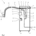
- the filling device 1 shown comprises a filling gun 2, described in more detail below, which is connected to a supply unit 3.
- the supply unit 3 is designed as a mobile cabinet in the embodiment shown in the drawings and has a fixed housing 4.
- a pressure-resistant and thermally insulated supply line 5 for liquid carbon dioxide which is connected to a source of liquid carbon dioxide not shown here, for example a tank, in which the liquid carbon dioxide is stored at a pressure of 20 bar and a temperature of approx. minus 20 ° C, is passed through the housing 4 of the supply unit 3 and opens at a multiple connector 6. Upstream of the multiple connector 6 is an electrical inside the housing 4 controllable control valve 7 arranged.
- phase detector 8 is also provided, which detects the proportions of gas phase and liquid phase of the carbon dioxide flowing through the feed line 5.
- a phase separation device (not shown here) can also be provided in the feed line 5, with which it is ensured that the carbon dioxide fed to the multiple connection 6 contains the greatest possible proportion of liquid phase.
- a discharge line 9 for gaseous carbon dioxide opens out at the multiple connection 6.
- the discharge line 9 is connected in a manner not shown here either to a device for reprocessing or to an exhaust air line leading into the open air.
- Discharge line 9 and supply line 5 can be thermally connected to one another via a heat exchanger, not shown here, by means of which the liquid passed through supply line 5 Carbon dioxide can be pre-cooled with the carbon dioxide gas passed through the discharge line 9.
- a branch line 11 branches off from the supply line 5, in which an evaporator 12 for evaporating liquid carbon dioxide and a control valve 13 are arranged.
- Branch line 11, evaporator 12 and control valve 13 are arranged inside the housing 4 of the supply unit 3.
- a pistol receptacle 14 into which the filling pistol 2 can be inserted in a resting phase before or after a filling process and connected to the housing 4 in a substantially gas-tight manner.
- An electrical heating device 15 for heating the inserted filling pistol 2 is provided in the pistol receptacle 14.
- a photoelectric unit 16 is provided within the housing 4, which is connected to an optical connector on the multiple connector 6 via two optical waveguides 17 (only one of which is shown here).
- the photoelectric unit 16 is integrated in a control and monitoring unit 18 with which the control valves 7, 13, the phase detector 8, the suction pump 10, the heating devices 15 and the evaporator 12 are also in data connection.
- the control and monitoring unit 18 is used to control the filling process in the manner described in more detail below.
- the supply unit is equipped with wheels 19 which are intended to facilitate transport of the supply unit 3 within the location; During normal operation, however, the supply unit 3 is fixed and is basically not moved during a filling process. Instead of the mobile form shown here, however, the supply unit can also be permanently installed at the location.
- the refrigerant receiving compartment 20 of a cooling container 21, which is equipped with walls 22 with good thermal insulation, comprises a cooling container 21 which is shown here only as a section Product receiving compartment 23 or several compartments for receiving products to be cooled as well as an insert 24 for inserting the refrigerant receiving compartment 20, which is designed as a drawer in the exemplary embodiment.
- a door opening 25 is provided on the front of the cooling container 21, which provides access to the product receiving compartment 23 and the refrigerant receiving compartment 20 and which can be closed with a door, not shown here.
- the refrigerant receiving compartment 20 has on its front side 26 two filling openings 28, 29, each equipped with a sealing ring 27, for liquid carbon dioxide and a gas outlet opening 30 for gaseous carbon dioxide.
- the filling openings 28, 29 are arranged horizontally next to one another at a distance of 5 to 10 cm.
- the gas outlet opening 30 is arranged above the filling openings 28, 29, for example 1 to 4 cm apart from them.
- a (lower) snow storage compartment 31 and an (upper) gas vent compartment 32 extend inside the refrigerant receiving compartment 20, which are separated from one another by a gas-permeable filter 33 in such a way that the gas outlet opening 30 into the gas vent compartment 32 and the filling openings 28, 29 into the snow receiving compartment 31 joins.
- the filter 33 preferably extends over the entire width of the refrigerant receiving compartment 20 in order to create the largest possible area for the passage of carbon dioxide gas when the device 1 is in operation.
- two reflectors 24, 35 are arranged in the immediate vicinity of the filling openings 28, 29 and the gas outlet opening 30.
- the reflectors 34, 35 are, for example, an area colored in a specific color.
- a ferromagnetic element for example an iron sheet 36, is arranged.
- the filling pistol 2 comprises a housing 37 made of a light, but low-temperature-resistant material, for example plastic, a light metal or a composite material, which has an orifice 38 and a connection opening 39.
- the mouth opening 38 which is equipped with a circumferential sealing element 40, for example a sealing lip made of a flexible, but low-temperature-resistant material, is dimensioned such that when the filling gun 2 is connected to the refrigerant receptacle 23, both the filling openings 28, 29 and the gas outlet opening 29 of the refrigerant receiving compartment 20 are covered.
- connection opening 39 of the housing 37 is used for gas-tight connection of a flexible gas discharge line 41, which in turn is connected to the multiple connection 6 of the supply unit 3 in a gas-tight, but detachable manner.
- the gas discharge line 41 is, for example, a corrugated hose made of a material that is resistant to low temperatures.
- a handle 42 is arranged on the housing 37.
- the filling gun 2 furthermore comprises an expansion nozzle 45 for supplying liquid carbon dioxide.
- the expansion nozzle 45 is equipped with two nozzle heads 46, 47 which protrude from a T-shaped front section 48 of the expansion nozzle 45 parallel to one another at a distance from one another which corresponds to the distance between the two filling openings 28, 29. This distance is between 5 cm and 10 cm, for example.
- the nozzle heads 46, 47 are each equipped with a nozzle opening 49, 50 which are inclined at an angle of between 0 and 30 ° with respect to the connecting axis of the two nozzle openings 49, 50 in the direction of the front section 48. In Fig. 3 a slight such inclination is indicated by dash-dotted lines at 49, 50.
- the nozzle heads 46, 47 are each pushed into the filling openings 28, 29 and protrude inside the snow receiving compartment 31 in such a way that the nozzle openings 49, 50 are each spaced 5 cm to 10 cm from the inner wall of the front side 26 .
- the expansion nozzle 45 is connected to a flexible and pressure-resistant carbon dioxide liquid supply line 52, which is routed within the gas discharge line 41 and is flow-connected to the supply line 5 at the multiple connector 6.
- the carbon dioxide liquid feed line 52 is accommodated within the gas discharge line 41 and establishes a flow connection to the feed line 5 at the multiple connection 6.
- the multiple connection 6 comprises, for example, a connection piece to which the gas discharge line 41 is firmly but detachably connected.
- a CO 2 liquid connection which is connected to the feed line 5 and to which the carbon dioxide liquid feed line is fixedly but also detachably fastened, is arranged within this connection piece.
- the filling pistol 2 is equipped with one or more, in the exemplary embodiment with two, optical waveguides 54, 55, which each end within the mouth opening 38 of the housing 37 with a conductor head 56, 57.
- the optical waveguides 54, 55 are passed through the housing 37 and the gas discharge line 41 and are optically connected to a respective optical waveguide 17 at a connection terminal arranged in the multiple connector 6.
- the optical waveguides 54, 55, 17 are constructed in a manner known per se and each have an optical fiber for emitted light and an optical waveguide for reflected light, the corresponding light-emitting and light-receiving units being arranged in the photoelectric unit 16.
- a permanent magnet 58 is mounted on the housing 37 within the mouth opening 27 in such a way that it interacts with the sheet iron 36 when the filling pistol is placed on the refrigerant receiving compartment 20.
- the device 1 has two operating modes, a sleep mode and a filling mode.
- the filling pistol 2 is received in the pistol receptacle 14 of the supply unit 3, the sealing element 40 producing an at least largely airtight connection.
- the control valves 7, 13 are closed.
- the suction pump 10 ensures a moderate negative pressure controlled by the control and monitoring unit 18, which is sufficient to hold the filling pistol 2 in the pistol receptacle 14, but which can easily be overcome manually in order to remove the filling pistol 2 from the pistol receptacle 14.
- a ferromagnetic element (not shown here) can also be arranged inside the pistol receptacle 14, which cooperates with the permanent magnet 58 when the filling pistol 2 is pushed in. If the expansion nozzle 45 has a low temperature due to a previous use, it is heated by means of the heating device 15 in order to prevent the accumulation of water on the surface of the expansion nozzle 45.
- the filling pistol 2 is first removed from the pistol receptacle 14 and placed on the front 26 of the refrigerant receiving compartment 20 in such a way that the nozzle heads 46, 47 are inserted into the respective filling openings 28, 29 and the Muzzle opening 38 of the filling gun 2 covers the gas outlet opening 30.
- the sealing element 40 ensures a gas-tight connection between the filling pistol 2 and the front side 26 of the refrigerant receptacle 20.
- the action of the suction pump 10 generates a negative pressure inside the refrigerant receptacle 20 and thus also inside the housing 37 of the filling pistol 2 , which is sufficient to hold the filling gun 2 on the refrigerant receiving compartment 20.
- a magnetic connection between permanent magnet 58 and sheet iron 36 provides additional security.
- optical signals are passed from an emitter of the photoelectric unit 16 through the optical waveguides 17, 54, which are reflected on the reflector 34.
- the reflected optical signals pass through the optical waveguides 54, 17 back to a detector of the photoelectric unit 16, where they are recorded and evaluated in the control and monitoring unit 18. If the control and monitoring unit 18 recognizes a correct position of the filling gun, the control valves 7, 13 are released for manual actuation.
- the optical waveguide 55 is used to determine the respective type of the refrigerant receiving compartment 20.
- the reflector 35 is designed specifically for a certain type of refrigerant receiving compartments 20 and has type-specific reflection properties which lead accordingly to different reflection signals transmitted to the control and monitoring unit 18. From this, the control and monitoring unit 18 determines the type of refrigerant receiving compartment and initiates a filling procedure corresponding to the type of refrigerant receiving compartment 20.
- the filling process is then started on the basis of a command entered manually into the control and monitoring unit 18.
- the carbon dioxide liquid feed line 52 is first flooded with gaseous carbon dioxide by opening the control valve 13 and starting the evaporator 12.
- liquid carbon dioxide is evaporated from the supply line 5 in the evaporator 12 and flows into the carbon dioxide liquid supply line 52.
- the purpose of the flooding is to create a pressure above the triple point pressure of 5.18 in the carbon dioxide liquid feed line 52 to generate bar in order to prevent that liquid carbon dioxide relaxes when entering the carbon dioxide liquid feed line 52 and the carbon dioxide snow generated thereby clogs the carbon dioxide liquid feed line 52.
- control valve 13 is closed and the evaporator 12 is switched off.
- the control valve 7 is then opened and liquid carbon dioxide flows at a pressure of, for example, 10 bar to 20 bar via the supply line 5 and the carbon dioxide liquid supply line 52 to the expansion nozzle 45, where it enters the snow receptacle 31 at the nozzle openings 49, 50.
- the control and monitoring unit 18 regulates, in particular, the supply of liquid carbon dioxide as a function of a gas phase component determined at the phase detector 8 and the suction strength of the suction pump 10 as a function of a pressure determined in the discharge line 9, upstream of the suction pump 10, by means of detectors not shown here .
- the liquid carbon dioxide relaxes and changes into a mixture of carbon dioxide snow and carbon dioxide gas. While the carbon dioxide snow is retained in the snow receiving compartment 31, the carbon dioxide gas produced during the expansion passes through the gas-permeable filter 33 into the gas vent compartment 32 and is drawn off by means of the suction pump 10 via the gas vent line 41 and the discharge line 9.
- the arrangement of the carbon dioxide liquid feed line 52 within the gas discharge line 41 serves to precool the liquid carbon dioxide and thus to increase the efficiency of the filling process.
- the evaporator 12 is switched on and the control valve 13 is opened. The control valve 7 is then closed.
- carbon dioxide gas flows into the carbon dioxide liquid feed line 52 and prevents liquid carbon dioxide still present in the carbon dioxide feed line 52 from being expanded with the formation of carbon dioxide snow and from clogging the carbon dioxide feed line 52.
- the control valve 13 is closed.
- the filling pistol 2 does not have any electrical components in its interior and, in particular, has a very low weight of, for example, less than 1 kg. Due to the low weight, the negative pressure generated by the suction pump 10 in the refrigerant receiving compartment 20 is generally sufficient to hold the filling pistol 2 on the refrigerant receiving compartment 20 during the filling.
- the light construction of the filling pistol 2 also makes it possible to dispense with complex crane arrangements for holding the filling pistol during the filling procedure.
- the filling gun 2 is moved and operated manually by an operator using the handle 42.
- the flexible parts of the gas discharge line 41 or the carbon dioxide liquid feed line 52 or the optical waveguides 54, 55 are sometimes subjected to severe stress due to bending and twisting.
- the gas discharge line 41, the carbon dioxide liquid feed line 52 and the optical waveguide 54, 55 on the multiple connector 6 and / or in the area of the connection opening 39 are each provided with one opposite the terminating nozzle 6 or the filling gun 2 rotatably or pivotably mounted connection piece (not shown here) equipped.
- the filling pistol 2a shown differs from the filling pistol 20 only in that it has a different expansion nozzle 45a. Otherwise, the same features are denoted by the same reference numerals as in the case of the filling gun 2.
- the expansion nozzle 45a has two nozzle heads 46a, 47a, which are arranged at a smaller distance from one another than the nozzle heads 46, 47 of the Relaxation nozzle 45. For example, the distance between the two nozzle heads 46a, 47a is 1 cm to 3 cm. In the case of the filling pistol 2a, too, the nozzle heads 46a, 47a are equipped with nozzle openings 49a, 50a directed towards one another.
- the filling pistol 20a is used to fill a refrigerant receiving compartment 20a, in the snow receiving compartment 31a of which there is only one filling opening 28a, into which the two nozzle heads 46a, 47a are jointly inserted for the purpose of filling the refrigerant receiving compartment 20a.
- a permanent magnet is present, which cooperates to establish a secure connection with a ferromagnetic element, likewise not shown, in the front side 26 of the refrigerant receiving compartment 20a.
- the filling pistol 20a between the nozzle heads 46a, 47a is parallel to the orifice 38a of the filling pistol 20a a retaining plate 59 is arranged which, during filling, seals off the parts of the filling opening 28a which are not filled by the nozzle heads 46a, 47a.
- Fig. 5 shows the jet pattern of the expansion nozzle 45a Fig. 4 in the by the line VV in Fig. 4 marked plane perpendicular to the longitudinal extent of the expansion nozzle 45a.
- the nozzle openings 49a, 50a of the respective nozzle heads 46a, 47a are directed towards one another, so that the two carbon dioxide jets 60, 61 exiting from the nozzle openings 49a, 50a and expanding in a fan-like manner collide with one another.
- the pulse currents of the two carbon dioxide jets 60, 61 cancel each other out, at least to a significant extent; in particular, there is no or only a slight force component which forces the expansion nozzle 45a out of the filling opening 28a.
- a turbulent flow is generated within the snow storage compartment 31a, due to which the dry ice particles generated during the expansion of the carbon dioxide are distributed very evenly in the snow storage compartment.
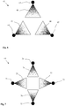
- the embodiment according to Fig. 6 shows an expansion nozzle 62 with three parallel nozzle heads 63, 64, 65 which - seen in cross section - are arranged in the form of an equilateral triangle.
- the nozzle heads 63, 64, 65 each have similar nozzle openings, which are each arranged at the same height on the nozzle heads 63, 64, 65 in such a way that the impulse flows of the carbon dioxide jets 66, 67, 68 flowing out of them cancel each other out.
- the nozzle opening of a nozzle head 63, 64, 65 points in each case to the center of the connecting line of the two remaining nozzle heads 64, 65, 63.
- FIG. 7 shows an expansion nozzle 69 with four parallel nozzle heads 70, 71, 72, 73 which - seen in cross section - are arranged in the form of a square.
- the nozzle heads 70, 71, 72, 73 each have similar nozzle openings, which are each arranged at the same height on the nozzle heads 70, 71, 72, 73 in such a way that the impulse flows of the carbon dioxide jets 74, 75, 76, 77 flowing out of them are mutually exclusive cancel.
- the nozzle openings each have opposing nozzle heads 70-72; 71-73 towards each other.
- expansion nozzles 62, 69 each correspond to corresponding filling openings of a refrigerant receiving compartment to be filled, whereby, similarly to the FIGS FIGS. 2 and 3 exemplary embodiments shown, each with separate filling openings for each nozzle head 63, 64, 65; 70, 71, 72, 73, or a common filling opening for all nozzle heads 63, 64, 65; 70, 71, 72, 73 of a relaxation nozzle 62, 69 can be provided.
- the preferred number of nozzle heads and / or nozzle openings depends in particular on the geometry of the refrigerant receiving compartment to be filled and the amount of carbon dioxide snow to be supplied. In any case, when designing the expansion nozzle, care should be taken to ensure that when the refrigerant receiving compartment is filled, the impulse flows of the carbon dioxide jets emerging from the nozzle openings at least substantially cancel each other out and that no or at least only a negligible resulting force effect in the axial direction occurs due to the emerging carbon dioxide jets that propel the expansion nozzle out of the filling opening or openings could.
- the embodiment according to the invention also discloses a
Landscapes
- Engineering & Computer Science (AREA)
- Chemical & Material Sciences (AREA)
- Chemical Kinetics & Catalysis (AREA)
- Combustion & Propulsion (AREA)
- Physics & Mathematics (AREA)
- Mechanical Engineering (AREA)
- Thermal Sciences (AREA)
- General Engineering & Computer Science (AREA)
- Filling Or Discharging Of Gas Storage Vessels (AREA)
- Carbon And Carbon Compounds (AREA)
Description
- Die Erfindung betrifft eine Füllvorrichtung zum Befüllen eines einem Kühlbehälter zum Kühlen von Produkten zugeordneten Kältemittel-Aufnahmefachs mit Kohlendioxidschnee, mit einer Versorgungseinheit und einer an die Versorgungseinheit koppelbaren Füllpistole, wobei die Füllpistole eine mit wenigstens einer Füllöffnung des Kältemittel-Aufnahmefachs verbindbare Entspannungsdüse zum Zuführen von flüssigem Kohlendioxid und eine mit einer Gasaustrittsöffnung des Kältemittel-Aufnahmefachs verbindbare Absaugöffnung zum Abführen von gasförmigem Kohlendioxid aufweist und mit der Versorgungseinheit über eine mit der Füllöffnung strömungsverbundene Kohlendioxid-Flüssigzuleitung und eine mit der Absaugöffnung strömungsverbundene Absaugleitung verbunden ist, und mit einem Steuerventil zum Regeln der Zufuhr von flüssigem Kohlendioxid in die Kohlendioxid-Flüssigzuleitung, einer Absaugeinrichtung zum Absaugen von gasförmigem Kohlendioxid aus der Absaugleitung und einer Steuer- und Kontrolleinheit zum Steuern des Füllvorgangs.
- Zum Transportieren von wärmeempfindlichen Produkten, insbesondere von Lebensmitteln wie Frisch- oder Tiefkühlprodukten, kommen mobile isotherme Kühlbehälter zum Einsatz, mit denen eine lückenlose Kühlkette von der Produktion bis zum Endkunden auch dann sichergestellt werden soll, wenn eine permanente Kühlung durch ein elektrisch betriebenes Kühlgerät nicht möglich ist. Derartige mobile Kühlbehälter weisen ein Produkt-Aufnahmefach für die Einlagerung der kühl zu haltenden Produkte sowie ein von diesem räumlich getrenntes, jedoch mit diesem thermisch verbundenes Kältemittel-Aufnahmefach für ein kryogenes Kältemittel auf. Das Kältemittel nimmt Wärme auf, die durch die Wände des Behälters dringt und sorgt so dafür, dass die Temperatur im Produkt-Aufnahmefach nicht steigt und das Produkt auf niedriger Temperatur gehalten wird. Dabei kommt es zur allmählichen Verdampfung oder Sublimation des Kältemittels. Durch die Wahl einer geeigneten thermischen Verbindung zwischen Produkt-Aufnahmefach und Kältemittel-Aufnahmefach kann das Produkt auf diese Weise über viele Stunden auf einer bestimmten tiefen Temperatur gehalten werden, ohne dass es dazu einer permanenten Energiezufuhr von außen bedarf. Die Kühlbehälter der in Rede stehenden Art sind so bemessen, dass sie mittels an ihnen befestigter Räder leicht von einer Person bewegt werden können. Typische Kühlbehälter haben beispielsweise eine auf den europäischen Palettenstandard beruhende Grundfläche von 600 mm x 800 mm bis 1200 mm x 800 mm und eine Höhe zwischen 1000 mm und 2000 mm sowie ein Nutzvolumen von beispielsweise zwischen 200 Litern und 1500 Litern. Da in der Regel bereits eine - gemessen an der Produktmenge - kleine Menge an Trockeneis zur Aufrechterhaltung einer hinreichend niedrigen Kühltemperatur über einen Zeitraum von einigen Stunden ausreicht, ist das Aufnahmefach für das Kältemittel sehr viel kleiner dimensioniert als das Fach zur Aufnahme der Produkte und hat beispielsweise ein Volumen zwischen 5 Litern und 50 Litern. Die vorliegende Erfindung bezieht sich auf eine Füllvorrichtung zum Befüllen derartiger Kältemittel-Aufnahmefächer.
- Ein Kühlbehälter der vorgenannten Art ist beispielsweise aus der
EP 0 942 244 A1 bekannt. Der Behälter weist ein schubladenartiges Kältemittel-Aufnahmefach für Kohlendioxidschnee auf, das thermisch und strömungstechnisch mit einem darunter angeordnetem Produkt-Aufnahmefach verbunden ist. Das Kältemittel- Aufnahmefach wird mit Kohlendioxidschnee mit einer Temperatur von -78°C beladen, der in den Kühlbehälter eindringende Wärme aufnimmt und dabei allmählich sublimiert. Aufgrund einer geeigneten Einstellung der Wärmeübertragung zwischen den Fächern können die Produkte zuverlässig auf einer Temperatur von beispielsweise 0°C bis 5°C (für Frischware) oder -15°C bis -25°C (Tiefkühlware) für mehr als 24 Stunden gehalten werden. - Zum Befüllen des Kältemittel-Aufnahmefachs eines solchen Kühlbehälters kommt eine in der
EP 1 088 191 B1 beschriebene Fülleinrichtung zu Einsatz. Die Fülleinrichtung weist eine Füllpistole sowie eine mit dieser verbundene Versorgungseinheit auf. Die Füllpistole ist mit einer Entspannungsdüse ausgerüstet, die in eine Füllöffnung des Kältemittel-Aufnahmefachs eingeführt wird, sowie mit einer Abzugseinrichtung, die mit einer Gasabzugsöffnung des Kältemittel-Aufnahmefachs verbunden wird. Beim Befüllen wird flüssiges Kohlendioxid zugeführt, das beim Austritt aus der Entspannungsdüse unter starker Abkühlung entspannt, wobei sich ein Gemisch aus Kohlendioxidschnee und Kohlendioxidgas bildet. Während der Kohlendioxidschnee von einem gasdurchlässigen Filter im Kältemittel-Aufnahmefach zurückgehalten wird, gelangt das Gas durch den Filter in die Gasabzugsöffnung und wird von einer Abzugseinrichtung aus dem Arbeitsbereich entfernt. Weiterhin ist die Füllpistole mit Anschlussarmaturen ausgerüstet, mit denen die Füllpistole im wesentlichen gasdicht mit dem Kältemittel-Aufnahmefach verbunden wird und die dafür sorgen, dass beim Füllvorgang möglichst kein Kohlendioxid in die Umgebung des Behälters entweicht. Da das Kohlendioxid mit hohem Druck zugeführt wird, ist die Füllpistole zudem mit Elektromagneten ausgestattet, die eine sichere Verbindung mit dem Kältemittel-Aufnahmefach herstellen. Ein in der Füllpistole angeordnetes Steuerventil, das die Zufuhr von Kohlendioxid regelt, kann erst geöffnet werden, wenn über gleichfalls in der Füllpistole angeordnete elektrische Detektoren eine korrekte Verbindung festgestellt wird. Die Versorgungseinheit umfasst Zu- und Ableitungen für das Kohlendioxid, eine mit dem Steuerventil, den Elektromagneten und den Detektoren elektrisch verbundene Steuereinheit sowie eine mechanische Haltevorrichtung, die es eine einhändige Bedienung der Füllpistole ermöglicht. - Ähnliche Systeme zum Befüllen von Kältemittel-Aufnahmefächern für Kühlbehälter mit Kohlendioxidschnee werden auch in der
WO2012/107518 A1 , derWO 2007/036656 A1 , derWO 2007/042727 A1 , derEP 2 645 024 A1 und derEP 2 336 684 A1 beschrieben. - Die aus dem Stand der Technik bekannten Füllvorrichtungen weisen oft den Nachteil auf, dass durch den Impulsstrom des mit hohem Druck aus der Entspannungsdüse austretenden Kohlendioxids eine Kraft auf die Entspannungsdüse ausgeübt wird, die diese aus dem Kältemittel-Aufnahmefach hinausdrängt. Um die Füllpistole während des Füllvorgangs sicher am Kältemittel-Aufnahmefach zu halten, kommen daher starke Elektromagnete zum Einsatz, die vor Beginn des Füllvorgangs eingeschaltet werden und in Zusammenwirken mit einem ferromagnetischen Element am Kühlmittel-Aufnahmefach eine feste Verbindung sicherstellen. Die zum Betreiben der Elektromagneten erforderlichen elektrischen Zuführungen und Anschlüsse innerhalb der Füllpistole müssen allerdings in aufwändiger Weise gegen Feuchtigkeit, Temperaturschwankungen und elektrostatische Aufladungen abgesichert werden, sodass diese Füllpistolen sehr komplex im Aufbau sind und ein hohes Eigengewicht besitzen, das die Handhabbarkeit erschwert. Zudem kann ein Fehler bei der Herstellung der elektromagnetischen Verbindung zwischen Füllpistole und Kältemittel-Aufnahmefach dazu führen, dass die Füllpistole mit hohem Druck aus der Füllöffnung des Kältemittel-Aufnahmefachs hinausgestoßen wird und umstehende Personen gefährdet. Weiterhin führen die bekannten Füllpistolen zu einer sehr ungleichmäßigen Verteilung des erzeugten Kohlendioxidschnees innerhalb des Schneeaufnahmefachs, die für die Kühlung der Produkte unvorteilhaft ist.
- Aufgabe der vorliegenden Erfindung ist daher, ein Füllsystem zum Befüllen eines einem Kühlbehälter zum Kühlen von Produkten zugeordneten Kältemittel-Aufnahmefachs mit Kohlendioxidschnee zu schaffen, bei dem die Gefahr, dass die Füllpistole während des Füllvorgangs aus dem Kältemittel-Aufnahmefach hinausgedrängt wird, minimiert ist, und bei dem der erzeugte Kohlendioxidschnee gleichmäßig im Innern des Schneeaufnahmefachs verteilt wird.
- Gelöst ist diese Aufgabe durch eine Füllvorrichtung mit den Merkmalen des Patentanspruchs 1.
- Erfindungsgemäß ist ein Vorderabschnitt der Entspannungsdüse mit wenigstens zwei parallel zueinander angeordneten Düsenköpfen ausgerüstet, die während der Befüllung in das Innere des Kältemittel-Aufnahmefachs vorstehen und die jeweils wenigstens eine Düsenöffnung aufweisen, wobei die Düsenöffnungen der Düsenköpfe derart aufeinander zu gerichtet sind, dass sich im Einsatz der Entspannungsdüse die Impulsströme der aus den Düsenöffnungen austretenden Kohlendioxidstrahlen zumindest weitgehend aufheben. Es entsteht somit keine oder nur eine geringe, die Entspannungsdüse aus dem Kältemittel-Aufnahmefach hinausdrängende, Kraftwirkung. Zudem führt diese Anordnung überraschenderweise zu einer sehr homogenen Verteilung des Kohlendioxidschnees im Innern des Kältemittel-Aufnahmefachs.
- Die Düsenköpfe und sind bevorzugt symmetrisch zueinander ausgebildet, besitzen also jeweils gleichartige Düsenöffnungen, die jeweils im gleichen Abstand vom Vorderabschnitt der Entspannungsdüse an den Düsenköpfen angeordnet sind. Im einfachsten Fall weist die Entspannungsdüse zwei Düsenköpfe auf, an denen auf gleicher Höhe gleichartige Düsenöffnungen angeordnet sind, die aufeinander zu gerichtet sind. Die Entspannungsdüse kann jedoch auch mehr als zwei Düsenköpfe aufweisen. In diesem Fall stehen die Düsenköpfe bevorzugt in gleichen Winkelabständen vom Vorderabschnitt der Entspannungsdüse vor. Beispielsweise sind drei Düsenköpfe vorgesehen, die parallel zueinander auf Basis eines gleichseitigen Dreiecks vom Vorderabschnitt der Entspannungsdüse vorstehen und deren Düsenöffnungen jeweils in Richtung der Winkelhalbierenden zwischen den Verbindungslinien zweier benachbarter Düsenköpfe gerichtet sind, sodass sich auch hier die Impulsströme der aus den drei Düsenköpfen austretenden Kohlendioxidstrahlen im wesentlichen aufheben. Im Falle von vier Düsenköpfen weisen die Düsenöffnungen von einander gegenüber liegenden Düsenköpfen aufeinander zu. Die Düsenköpfe sind bevorzugt so angeordnet, dass die Düsenköpfe bzw. die aufeinander zu gerichteten Düsenöffnungen einen Abstand zwischen 1 cm und 10 cm zueinander aufweisen. Zum Anschließen eines Düsenkopfs ist das Kältemittel-Aufnahmefach bevorzugt mit separaten Füllöffnungen für die einzelnen Düsenköpfe ausgestattet, die bevorzugt einen Abstand zwischen 5 cm und 10 cm voneinander aufweisen. In Fällen, in denen es - beispielsweise aus Platzgründen - nicht möglich ist, am Kältemittel-Aufnahmefach zwei oder mehr Füllöffnungen im Abstand von 5 cm bis 10 cm vorzusehen, ist es im Rahmen der Erfindung auch möglich, den Abstand der Düsenköpfe näher als 5 cm voneinander zu wählen, beispielsweise 1 cm bis 3 cm. In diesem Fall ist im Kältemittel-Aufnahmefach eine gemeinsame Füllöffnung für mehrere oder für alle Düsenköpfe vorgesehen. Auch eine Mehrzahl von Düsenöffnungen an jedem Düsenkopf ist vorstellbar, jedoch gilt auch hier, dass sich die Impulsströme des aus den Düsenöffnungen aller Düsenköpfe austretenden Kohlendioxids gegenseitig ganz oder weitgehend aufheben und es aufgrund der Impulsströme des aus den Düsenöffnungen austretenden Kohlendioxids zu keiner oder zu keiner wesentlichen, die Düsenköpfe aus der jeweiligen Füllöffnung herausdrängenden resultierenden Kraftwirkung kommt.
- Die Düsenöffnungen der Düsenköpfe sind erfindungsgemäß in Richtung des Vorderabschnitts der Entspannungsdüse geneigt angeordnet; bevorzugt beträgt der Neigungswinkel dabei bis zu 30°. Im Betrieb der Vorrichtung wird dadurch ein Teil der bei der Entspannung des Kohlendioxids entstehenden Kohlendioxidpartikel gegen die Innenseite der der Füllpistole zugewandten Wand des Kältemittel-Aufnahmefachs gestrahlt, von dort reflektiert und in einen hinteren Teil des Kältemittel-Aufnahmefachs geschleudert. Dadurch wird eine besonders homogene Verteilung des Kohlendioxidschnees im Kältemittel-Aufnahmefach erzielt.
- Die Entspannungsdüse sowie eine Absaugöffnung der Füllpistole sind in bzw. an einem gemeinsamen Gehäuse angeordnet, das bevorzugt aus einem leichten Material, beispielsweise aus einem Leichtmetall besteht. Entspannungsdüse und Absaugöffnung der Füllpistole sind dabei der jeweiligen Anordnung von Füllöffnung und Gasaustrittsöffnung am Kältemittel-Aufnahmefach angepasst. Beispielsweise sind Füllöffnung und Gasabzugsöffnung des Kältemittel-Aufnahmefachs beabstandet voneinander oder konzentrisch zueinander angeordnet, und demzufolge sind auch die zum Einsatz kommende Entspannungsdüse und die Absaugöffnung beabstandet voneinander oder konzentrisch zueinander angeordnet. Die Füllpistole ist bevorzugt lösbar mit der Versorgungseinheit verbunden; soll mit der erfindungsgemäßen Vorrichtung ein Kältemittel-Aufnahmefach eines anderen Typs gefüllt werden, kann in einfacher Weise die Füllpistole von der Versorgungseinheit getrennt und durch eine entsprechend andere Füllpistole ersetzt werden.
- Die Füllpistole ist bevorzugt derart ausgestaltet, dass die Entspannungsdüse innerhalb der Absaugöffnung angeordnet ist. Beispielsweise ist die Absaugeinrichtung als eine mit flexiblen Dichtelementen ausgerüstete Haube ausgebildet, die im Einsatz der Füllpistole derart auf das Kältemittel-Aufnahmefach aufgepresst wird, dass sie sowohl die Füllöffnung als auch die Gasaustrittsöffnung des Kältemittel-Aufnahmefachs überdeckt, während zugleich die innerhalb der Haube vorstehende Entspannungsdüse gasdicht mit der Füllöffnung verbunden ist. Dadurch wird insbesondere die Anlagerung von Feuchtigkeit an die Entspannungsdüse während des Füllvorgangs verhindert.
- Grundsätzlich kann die erfindungsgemäße Entspannungsdüse in vielen aus dem Stand der Technik bekannten Füllpistolen installiert werden. Eine besonders vorteilhafte Ausgestaltung der Erfindung sieht jedoch vor, dass die Füllpistole weder ein die Zuführung des flüssigen Kohlendioxids steuerndes Ventil noch elektrische Komponenten enthält, insbesondere keine elektrischen Steuerungen und Ventile, elektrische Sensoren oder Elektromagnete. Diese sind stattdessen innerhalb der Versorgungseinheit, räumlich getrennt von der Füllpistole, angeordnet. Diese Komponenten sind dadurch gut vor negativen Einwirkungen durch Feuchtigkeit, Temperatur oder mechanischen Einwirkungen geschützt. Die Füllpistole zeichnet sich dadurch durch einen sehr einfachen Aufbau und ein geringes Eigengewicht aus, wodurch die Bedienung wesentlich erleichtert wird; insbesondere kann auf eine Krananordnung zum Halten der Füllpistole während der Befüllung verzichtet werden. Füllpistole und Versorgungseinheit sind lediglich über eine Kohlendioxid-Flüssigzuleitung, eine Gasabzugsleitung und gegebenenfalls einen oder mehrere Lichtwellenleitern miteinander verbunden, die jeweils in Form flexibler Leitungen ausgestaltet sind und somit einer Bedienperson eine große Bewegungsfreiheit verschaffen.
- Die beispielsweise als Schrank ausgebildete Versorgungseinheit ist während des Füllvorgangs grundsätzlich ortsfest aufgestellt und beispielsweise an entsprechende Zu- und Ableitungen für Kohlendioxid eines Versorgungsnetzwerks am Standort angeschlossen. Dies schließt freilich nicht aus, dass die Versorgungseinheit während einer Betriebspause bewegt werden kann und zu diesem Zweck geeignete Transporteinrichtungen, wie etwa Räder, vorgesehen sein können.
- Sowohl die Absaugleitung als auch die Kohlendioxid-Flüssigzuleitung sind bevorzugt aus einem flexiblen Material gefertigt und besitzen eine Länge von 1m bis 3m oder darüber, um einer Bedienperson eine große Bewegungsfreiheit beim Anschließen des Kältemittel-Aufnahmefachs eines mobilen Kühlbehälters der eingangs genannten Art an die Fülleinrichtung zu ermöglichen.
- Im Betrieb der erfindungsgemäßen Vorrichtung wird die Füllpistole mit einem Kältemittel-Aufnahmefach verbunden. Das Kältemittel-Aufnahmefach beinhaltet ein mit wenigstens einer Füllöffnung ausgerüstetes Schneeaufnahmefach und ein bevorzugt oberhalb des Schneeaufnahmefachs angeordnetes Gasabzugsfach, das mit einer Gasabzugsöffnung ausgerüstet ist. Schneeaufnahmefach und Gasabzugsfach sind durch einen gasdurchlässigen Filter voneinander getrennt. Beim Anschluss der Füllpistole wird die Entspannungsdüse in die Füllöffnung(en) des Kältemittel-Aufnahmefachs eingeführt, und die Abzugsöffnung überdeckt die Gasabzugsöffnung des Gasabzugsfachs. Um das Eindringen von Umgebungsluft zu vermeiden, sind dabei Füllöffnung und/oder Gasabzugsöffnung des Kältemittel-Aufnahmefachs und/oder Entspannungsdüse und/oder Abzugsöffnung der Füllpistole mit geeigneten Dichtelementen ausgerüstet. Das Kohlendioxid wird im zumindest überwiegend flüssigen Zustand bei einem Druck oberhalb des Tripelpunktdrucks von Kohlendioxid (5,18 bar) an die Entspannungsdüse geführt und entspannt beim Austritt aus der Entspannungsdüse in das Schneeaufnahmefach auf Umgebungsdruck, wobei ein Gemisch aus Kohlendioxidgas und Kohlendioxidschnee gebildet wird. Während der Kohlendioxidschnee im Schneeaufnahmefach zurückgehalten wird, durchdringt das Kohlendioxidgas den gasdurchlässigen Filter und wird von der Absaugeinrichtung durch die Absaugleitung abgezogen. Der von der Absaugeinrichtung erzeugte Unterdruck ist dabei so bemessen, dass die Füllpistole unter der Wirkung des Umgebungsdrucks auf das Kältemittel-Aufnahmefach aufgepresst wird, wobei mittels der Dichtelemente eine gasdichte Verbindung hergestellt wird, die das Entweichen von Kohlendioxid in die Umgebung verhindert.
- Um zu verhindern, dass zu Beginn eines Füllvorgangs flüssiges Kohlendioxid beim Eindringen in den Abschnitt der Kohlendioxid-Flüssigzuleitung zwischen Steuerventil und Füllpistole entspannt und dabei Kohlendioxidschnee gebildet wird, der die Kohlendioxid-Flüssigzuleitung verstopfen kann, wird die Kohlendioxid-Flüssigzuleitung vor und nach der Befüllung mit Kohlendioxidgas geflutet, das unter einem Druck oberhalb des Tripelpunktdrucks von Kohlendioxid zugeführt wird. Beispielsweise wird die Kohlendioxid-Flüssigzuleitung vor der Zuführung von flüssigem Kohlendioxid für eine Zeitdauer von 0,5 bis 1s und nach dem Abstellen der Zufuhr von flüssigem Kohlendioxid für eine Zeitdauer von 0,5 bis 3s mit unter Druck stehendem Kohlendioxidgas geflutet. Das hierzu erforderliche Kohlendioxidgas wird zweckmäßigerweise in der Versorgungseinheit durch Verdampfen von flüssigem Kohlendioxid gewonnen.
- Um unter Verzicht auf elektrische Komponenten innerhalb der Füllpistole das Bestehen einer sicheren Verbindung zwischen der Füllpistole und dem Kältemittel-Aufnahmefach anzeigen zu können, eignen sich beispielsweise mechanische Mittel, beispielsweise zueinander korrespondierend geformte Elemente an der Füllpistole und am Kältemittel-Aufnahmefach. Eine besonders vorteilhafte Ausgestaltung der Erfindung sieht jedoch vor, dass die in der Versorgungseinheit angeordnete Steuer- und Kontrolleinheit mit einer fotoelektrischen Einheit zum Feststellen des Bestehens einer sicheren Verbindung ausgerüstet ist, die mit Lichtwellenleitern in der Füllpistole verbunden ist. Die fotoelektrische Einheit sendet und empfängt dabei optische Signale über die Lichtwellenleiter an einen bzw. von einem am Kältemittel-Aufnahmefachs angeordneten Reflektor. Elektrischen Komponenten innerhalb der Füllpistole sind dabei nicht erforderlich.
- Eine feste, jedoch lösbare Verbindung zwischen Füllpistole und Kältemittel-aufnahmefach wird im einfachsten Fall dadurch hergestellt, dass die Saugleistung der Absaugeinrichtung so eingestellt wird, dass die Füllpistole auch während des Füllvorgangs unter der Wirkung der Saugkraft an die Kältemittel-Aufnahmefach angepresst wird. Um die Sicherheit der Verbindung zu erhöhen ist es allerdings vorteilhaft, dass die Füllpistole und/oder das Kältemittel-Aufnahmefach wenigstens einen Permanentmagneten aufweist/aufweisen, der/die mit einem weiteren Permanentmagneten oder einer ferromagnetischen Fläche am Kältemittel-Aufnahmefach bzw. der Füllpistole zusammenwirkt/zusammenwirken.
- Zweckmäßigerweise ist die Kohlendioxid-Flüssigzuleitung zumindest abschnittsweise, bevorzugt zumindest über die gesamte Strecke zwischen Füllpistole und Versorgungseinheit, innerhalb der Absaugleitung angeordnet. Dadurch wird das durch die Zuführleitung transportierte flüssige Kohlendioxid vom kaltem gasförmigem Kältemittel vorgekühlt, das im Gegenstrom durch die Abführleitung abgesaugt wird. Zudem erfordert die innerhalb der Absaugleitung angeordnete Zuführleitung keine thermischen Isolationen, wodurch die Zuführleitung leichter und flexibler ausgeführt werden kann, was insgesamt die Handhabung der Füllpistole erleichtert. Im Übrigen kann dem Kältemittel-Aufnahmefach auch flüssiges Kohlendioxid zugeführt werden, das zuvor in einem Unterkühler auf eine Temperatur unterhalb seines Siedepunkts gebracht wurde.
- Die Absaugleitung und/oder die Kohlendioxid-Flüssigleitung und/oder die Lichtwellenleiter sind dabei bevorzugt aus einem flexiblen Material gefertigt. Um die Handhabung der Vorrichtung weiter zu erleichtern, ist/sind die Absaugleitung und/oder die Kohlendioxid-Flüssigleitung und/oder die Lichtwellenleiter vorzugsweise mit dreh- oder schwenkbar an der Füllpistole und/oder der Versorgungseinheit angelenkten Verbindungsmitteln, beispielsweise über Drehflansche, befestigt.
- Bevorzugt ist die Absaugeinrichtung so ausgelegt, das im Betrieb der Füllvorrichtung ein Unterdruck im Bereich des Kältemittel-Aufnahmefachs herstellbar ist, der so bemessen sein sollte, dass er ausreicht, um die Füllpistole am Kältemittel-Aufnahmefach zu halten.
- Der Kühlbehälter kann im Übrigen auch ein Kältemittel-Aufnahmefach aufweisen, das in wenigstens zwei voneinander getrennte Teilfächer unterteilt ist, die jeweils über Wärmebrücken mit unterschiedlichem Wärmewiderstand mit einem Produktaufnahmefach des Kühlbehälters verbunden sind. Beispielsweise weist eines der Teilfächer eine sehr gute Wärmeleitung, das andere Teilfach dagegen eine schlechtere Wärmeleitung zum Produkt-Aufnahmefach auf. Wird nur das Teilfach mit der guten Wärmeleitung mit Kohlendioxid befüllt, werden die Produkte für eine kürzere Zeit auf eine tiefere Temperatur gekühlt. Wird dagegen das Teilfach mit der schlechteren Wärmeleitung befüllt, erfolgt eine Kühlung der Produkte auf eine weniger niedrige Temperatur, die jedoch für einen längeren Zeitraum anhält. Die einzelnen Teilfächer weisen dabei jeweils getrennte Füllöffnungen und Gasaustrittsöffnungen auf.
- Anhand der Zeichnungen sollen Ausführungsbeispiele der Erfindung näher erläutert werden. In schematischer Ansicht zeigen:
- Fig. 1:
- Eine erfindungsgemäße Vorrichtung mit Füllpistole und Versorgungseinheit,
- Fig. 2:
- Einen Kühlbehälter mit einem zu füllenden Kältemittel-Aufnahmefach mit der Füllpistole aus
Fig. 1 in einer seitlich aufgeschnittenen Ansicht, - Fig. 3:
- Die Füllpistole aus
Fig. 1 und2 in einer vergrößerten Schnittansicht von unten. - Fig. 4:
- Eine Füllpistole und ein Kältemittel-Aufnahmefach in einer alternativen Ausführungsform in einer Schnittansicht von unten,
- Fig. 5:
- Das Strahlbild eines erfindungsgemäßen, mit zwei Entspannungsdüsen ausgerüsteten Düsenkopfs,
- Fig. 6:
- Das Strahlbild eines erfindungsgemäßen, mit drei Entspannungsdüsen ausgerüsteten Düsenkopfs,
- Fig. 7:
- Das Strahlbild eines erfindungsgemäßen, mit vier Entspannungsdüsen ausgerüsteten Düsenkopfs.
- Die in
Fig. 1 dargestellte Füllvorrichtung 1 umfasst eine unten näher beschriebene Füllpistole 2, die an eine Versorgungseinheit 3 angeschlossen ist. Die Versorgungseinheit 3 ist im in den Zeichnungen gezeigten Ausführungsbeispiel als mobiler Schrank ausgebildet und besitzt ein festes Gehäuse 4. Eine druckfeste und thermisch isolierte Zuleitung 5 für flüssiges Kohlendioxid, die an eine hier nicht gezeigte Quelle für flüssiges Kohlendioxid angeschlossen ist, beispielsweise einem Tank, in dem das flüssige Kohlendioxid bei einem Druck von 20 bar und einer Temperatur von ca. minus 20°C bevorratet wird, ist durch das Gehäuse 4 der Versorgungseinheit 3 geführt und mündet an einem Mehrfachanschluss 6. Stromauf zum Mehrfachanschluss 6 ist innerhalb des Gehäuses 4 ein elektrisch ansteuerbares Steuerventil 7 angeordnet. Im Ausführungsbeispiel nachFig. 1 ist weiterhin ein Phasendetektor 8 vorgesehen, der die Anteile von Gasphase und flüssiger Phase des durch die Zuleitung 5 strömenden Kohlendioxids erfasst. Optional kann des Weiteren in der Zuleitung 5 eine hier nicht gezeigte Einrichtung zur Phasentrennung vorgesehen sein, mit der sichergestellt wird, das das zum Mehrfachanschluss 6 geführte Kohlendioxid einen größtmöglichen Anteil an flüssiger Phase enthält. - Am Mehrfachanschluss 6 mündet eine Ableitung 9 für gasförmiges Kohlendioxid aus, in der eine elektrische Saugpumpe 10 angeordnet ist. Die Ableitung 9 ist in hier nicht gezeigter Weise entweder mit einer Einrichtung zur Wiederaufbereitung oder mit einer ins Freie führenden Abluftleitung verbunden. Ableitung 9 und Zuleitung 5 können über einen hier nicht gezeigten Wärmetauscher thermisch miteinander verbunden sein, mittels dessen das durch die Zuleitung 5 geführte flüssige Kohlendioxid mit dem durch die Ableitung 9 geführten Kohlendioxidgas vorgekühlt werden kann.
- Von der Zuleitung 5 geht eine Zweigleitung 11 ab, in der ein Verdampfer 12 zum Verdampfen von flüssigem Kohlendioxid sowie ein Steuerventil 13 angeordnet ist. Zweigleitung 11, Verdampfer 12 und Steuerventil 13 sind innerhalb des Gehäuses 4 der Versorgungseinheit 3 angeordnet.
- Im Gehäuse 4 der Versorgungseinheit 3 ist des Weiteren eine Pistolenaufnahme 14 angeordnet, in die die Füllpistole 2 in einer Ruhephase vor oder nach einem Füllvorgang eingeführt und dabei im wesentlichen gasdicht mit dem Gehäuse 4 verbunden werden kann. In der Pistolenaufnahme 14 ist eine elektrische Heizeinrichtung 15 zur Beheizung der eingeführten Füllpistole 2 vorgesehen.
- Weiterhin ist innerhalb des Gehäuses 4 eine fotoelektrische Einheit 16 vorgesehen, die über zwei Lichtwellenleiter 17 (von denen hier nur einer gezeigt ist) mit einem optischen Anschluss am Mehrfachanschluss 6 verbunden ist. Die fotoelektrische Einheit 16 ist in einer Steuer- und Kontrolleinheit 18 integriert, mit der auch die Steuerventile 7, 13, der Phasendetektor 8, die Saugpumpe 10, die Heizeinrichtungen 15 und der Verdampfer 12 in Datenverbindung stehen. Die Steuer- und Kontrolleinheit 18 dient dazu, den Befüllvorgang in der unten näher beschriebenen Weise zu steuern.
- Im gezeigten Ausführungsbeispiel ist die Versorgungseinheit mit Rädern 19 ausgerüstet, die einen Transport der Versorgungseinheit 3 innerhalb des Standortes erleichtern sollen; während des üblichen Betriebs ist die Versorgungseinheit 3 jedoch fixiert und wird während eines Füllvorgangs grundsätzlich nicht bewegt. Anstelle der hier gezeigten mobile Form kann die Versorgungseinheit jedoch auch fest am Standort installiert sein.
- Die anhand der
Fig. 2 und 3 näher erläuterte Füllpistole 2 dient zum Befüllen eines (inFig. 3 nur ausschnittsweise dargestellten) Kältemittel-Aufnahmefachs 20 eines Kühlbehälters 21. Der mit thermisch gut isolierten Wänden 22 ausgerüstete Kühlbehälter 21 umfasst ein hier nur ausschnittsweise dargestelltes Produktaufnahmefach 23 oder mehrere Fächer zum Aufnehmen von zu kühlenden Produkten sowie einen Einsatz 24 zum Einschieben des im Ausführungsbeispiel als Schublade ausgebildeten Kältemittel-Aufnahmefachs 20. Frontseitig ist am Kühlbehälter 21 eine Türöffnung 25 vorgesehen, die den Zugang zum Produktaufnahmefach 23 und dem Kältemittel-Aufnahmefach 20 ermöglicht und die mit einer hier nicht gezeigten Türe verschlossen werden kann. - Das Kältemittel-Aufnahmefach 20 besitzt an seiner Frontseite 26 zwei jeweils mit einem Dichtring 27 ausgerüstete Füllöffnungen 28, 29 für flüssiges Kohlendioxid sowie eine Gasaustrittsöffnung 30 für gasförmiges Kohlendioxid. Im Ausführungsbeispiel sind die Füllöffnungen 28, 29 im Abstand von 5 bis 10 cm horizontal nebeneinander angeordnet. Die Gasaustrittsöffnung 30 ist oberhalb der Füllöffnungen 28, 29, beispielsweise 1 bis 4 cm von diesen beabstandet angeordnet. Innerhalb des Kältemittel-Aufnahmefachs 20 erstreckt sich ein (unteres) Schneeaufnahmefach 31 und ein (oberes) Gasabzugsfach 32, die durch einen gasdurchlässigen Filter 33 derart voneinander getrennt sind, dass die Gasaustrittsöffnung 30 in das Gasabzugsfach 32 und die Füllöffnungen 28, 29 in das Schneeaufnahmefach 31 einmündet. Der Filter 33 erstreckt sich dabei bevorzugt über die ganze Breite des Kältemittel-Aufnahmefachs 20, um im Betrieb der Vorrichtung 1 eine möglichst große Fläche für den Durchtritt von Kohlendioxidgas zu schaffen. Auf der Frontseite 26 des Kältemittel-Aufnahmefachs 20 sind in unmittelbarer Nähe der Füllöffnungen 28, 29 und der Gasaustrittsöffnung 30 zwei Reflektoren 24, 35 angeordnet. Bei den Reflektoren 34, 35 handelt es sich beispielsweise um eine in einer bestimmten Farbe eingefärbte Fläche. Ebenfalls in Nähe der Öffnungen 28, 29 - im Ausführungsbeispiel unterhalb der Füllöffnungen 28 - ist ein ferromagnetisches Element, beispielweise ein Eisenblech 36 angeordnet.
- Die Füllpistole 2 umfasst ein Gehäuse 37 aus einem leichten, jedoch tieftemperaturfesten Material, beispielsweise Kunststoff, einem Leichtmetall oder einem Kompositmaterial, das eine Mündungsöffnung 38 und eine Anschlussöffnung 39 aufweist. Die mit einem rundumlaufenden Dichtelement 40, beispielsweise einer Dichtlippe aus einem flexiblen, jedoch tieftemperaturbeständigen Material, ausgerüstete Mündungsöffnung 38 ist so dimensioniert, dass sie beim Anschließen der Füllpistole 2 an das Kältemittel-Aufnahmefach 23 sowohl die Füllöffnungen 28, 29 als auch die Gasaustrittöffnung 29 des Kältemittel-Aufnahmefachs 20 überdeckt. Die Anschlussöffnung 39 des Gehäuses 37 dient zum gasdichten Anschließen einer flexiblen Gasabzugsleitung 41, die ihrerseits mit dem Mehrfachanschluss 6 der Versorgungseinheit 3 gasdicht, jedoch lösbar, verbunden ist. Bei der Gasabzugsleitung 41 handelt es sich beispielsweise um einen Wellschlauch aus einem tieftemperaturfesten Material. Weiterhin ist am Gehäuse 37 ein Handgriff 42 angeordnet.
- Die Füllpistole 2 umfasst des Weiteren eine Entspannungsdüse 45 zum Zuführen von flüssigem Kohlendioxid. Die Entspannungsdüse 45 ist mit zwei Düsenköpfen 46, 47 ausgerüstet, die von einem T-förmig verlaufenden Vorderabschnitt 48 der Entspannungsdüse 45 parallel zueinander mit einem Abstand voneinander vorstehen, der dem Abstand der beiden Füllöffnungen 28, 29 entspricht. Dieser Abstand beträgt beispielsweise zwischen 5 cm und 10 cm. Die Düsenköpfe 46, 47 sind im Ausführungsbeispiel mit jeweils einer Düsenöffnung 49, 50 ausgerüstet, die mit einem Winkel von jeweils zwischen 0 und 30° gegenüber der Verbindungsachse der beiden Düsenöffnungen 49, 50 in Richtung zum Vorderabschnitt 48 geneigt sind. In
Fig. 3 ist eine geringe derartige Neigung durch strichpunktierte Linien an 49, 50 angedeutet. Bei bestimmungsgemäß aufgesetzter Füllpistole 2 sind die Düsenköpfe 46, 47 jeweils in die Füllöffnungen 28, 29 eingeschoben und stehen im Innern des Schneeaufnahmefachs 31 derart vor, dass die Düsenöffnungen 49, 50 jeweils um 5 cm bis 10 cm von der Innenwand der Frontseite 26 beabstandet sind. Auf ihrer von den Düsenköpfen 46, 47 entgegengesetzten Hinterabschnitt 51 ist die Entspannungsdüse 45 an eine flexible und druckfeste Kohlendioxid-Flüssigzuleitung 52 angeschlossen, die innerhalb der Gasabzugsleitung 41 geführt ist und am Mehrfachanschluss 6 mit der Zuleitung 5 strömungsverbunden ist. Die Kohlendioxid-Flüssigzuleitung 52 ist innerhalb der Gasabzugsleitung 41 aufgenommen und stellt am Mehrfachanschluss 6 eine Strömungsverbindung mit der Zuleitung 5 her. Der Mehrfachanschluss 6 umfasst dazu beispielsweise einen Anschlussstutzen, an dem die Gasabzugsleitung 41 fest, jedoch lösbar verbunden ist. Innerhalb dieses Anschlussstutzens ist ein mit der Zuleitung 5 verbundener CO2-Flüssiganschluss angeordnet, an dem die Kohlendioxid-Flüssigzuleitung fest, jedoch gleichfalls lösbar befestigt ist. - Weiterhin ist die Füllpistole 2 mit einer oder mehreren, im Ausführungsbeispiel mit zwei, Lichtwellenleitern 54, 55 ausgerüstet, die innerhalb der Mündungsöffnung 38 des Gehäuses 37 mit jeweils einem Leiterkopf 56, 57 enden. Die Lichtwellenleiter 54, 55 sind durch das Gehäuse 37 und die Gasabzugsleitung 41 hindurchgeführt und an einer im Mehrfachanschluss 6 angeordneten Verbindungsanschluss mit jeweils einem Lichtwellenleiter 17 optisch verbunden. Die Lichtwellenleiter 54, 55,17 sind in an sich bekannter Weise aufgebaut und weisen jeweils einen Lichtfaser für emittiertes Licht und einen Lichtwellenleiter für reflektiertes Licht auf, wobei die entsprechenden lichtemittierenden und lichtempfangenden Einheiten in der fotoelektrischen Einheit 16 angeordnet sind.
- Weiterhin ist ein Permanentmagnet 58 derart am Gehäuse 37 innerhalb der Mündungsöffnung 27 montiert, dass er beim Aufsetzen der Füllpistole auf das Kältemittel-Aufnahmefach 20 mit dem Eisenblech 36 zusammenwirkt.
- Im Betrieb weist die Vorrichtung 1 zwei Betriebsmodi auf, einen Ruhemodus und einen Füllmodus. Im Ruhemodus ist die Füllpistole 2 in der Pistolenaufnahme 14 der Versorgungseinheit 3 aufgenommen, wobei das Dichtelement 40 einen zumindest weitgehend luftdichte Verbindung herstellt. Die Steuerventile 7, 13 sind geschlossen. Die Saugpumpe 10 sorgt für einen von der Steuer- und Kontrolleinheit 18 kontrollierten, moderaten Unterdruck, der ausreicht, um die Füllpistole 2 in der Pistolenaufnahme 14 zu halten, jedoch manuell leicht überwunden werden kann, um die Füllpistole 2 aus der Pistolenaufnahme 14 zu entnehmen. Im Übrigen kann auch innerhalb der Pistolenaufnahme 14 ein - hier nicht gezeigtes - ferromagnetisches Element angeordnet sein, dass bei eingeschobener Füllpistole 2 mit dem Permanentmagneten 58 zusammenwirkt. Sofern die Entspannungsdüse 45 aufgrund eines vorhergehenden Einsatzes eine tiefe Temperatur aufweist, wird sie mittels der Heizeinrichtung 15 beheizt, um die Anlagerung von Wasser auf der Oberfläche der Entspannungsdüse 45 zu verhindern.
- Im Füllmodus wird vor der Befüllung eines Kältemittel-Aufnahmefachs 20 zunächst die Füllpistole 2 aus der Pistolenaufnahme 14 entnommen und derart auf die Frontseite 26 des Kältemittel-Aufnahmefachs 20 aufgesetzt, dass die Düsenköpfe 46, 47 in die jeweiligen Füllöffnungen 28, 29 eingeführt werden und die Mündungsöffnung 38 der Füllpistole 2 die Gasaustrittsöffnung 30 überdeckt. Dabei sorgt das Dichtelement 40 für eine gasdichte Verbindung zwischen Füllpistole 2 und der Frontseite 26 des Kältemittel-Aufnahmefachs 20. Durch die Wirkung der Saugpumpe 10 wird im Innern des Kältemittel-Aufnahmefachs 20 und damit auch im Innern des Gehäuses 37 der Füllpistole 2 ein Unterdruck erzeugt, der ausreicht, um die Füllpistole 2 am Kältemittel-Aufnahmefach 20 zu halten. Eine magnetische Verbindung zwischen Permanentmagnet 58 und Eisenblech 36 sorgt für eine zusätzliche Sicherung.
- Um sicherzustellen, dass die Füllpistole 2 korrekt aufgesetzt wurde, werden von einem Emitter der fotoelektrischen Einheit 16 optische Signale durch die Lichtwellenleiter 17, 54 geleitet, die an dem Reflektor 34 reflektiert werden. Die reflektierten optischen Signale gelangen durch die Lichtwellenleiter 54, 17 zurück zu einem Detektor der fotoelektrischen Einheit 16, wo sie erfasst und in der Steuer- und Kontrolleinheit 18 ausgewertet werden. Erkennt die Steuer- und Kontrolleinheit 18 eine korrekte Position der Füllpistole, werden die Steuerventile 7, 13 zur manuellen Betätigung freigegeben.
- Der Lichtwellenleiter 55 wird dazu eingesetzt, den jeweiligen Typ des Kältemittel-Aufnahmefachs 20 festzustellen. Hierzu ist der Reflektor 35 spezifisch für einen bestimmten Typ von Kältemittel-Aufnahmefächern 20 ausgebildet und besitzt typenspezifische Reflexionseigenschaften, die entsprechend zu unterschiedlichen, an die Steuer- und Kontrolleinheit 18 übermittelten Reflexionssignalen führen. Hieraus bestimmt die Steuer- und Kontrolleinheit 18 den Typ des Kältemittel-Aufnahmefachs und leitet eine dem Typ des Kältemittel-Aufnahmefachs 20 entsprechende Füllprozedur ein.
- Anschließend wird aufgrund eines manuell in die Steuer- und Kontrolleinheit 18 eingegebenen Befehls der Füllvorgang in Gang gesetzt. Dazu wird zunächst die Kohlendioxid-Flüssigzuleitung 52 mit gasförmigem Kohlendioxid geflutet, indem das Steuerventil 13 geöffnet und der Verdampfer 12 in Gang gesetzt wird. Dadurch wird flüssiges Kohlendioxid aus der Zuleitung 5 im Verdampfer 12 verdampft und strömt in die Kohlendioxid-Flüssigzuleitung 52 ein. Die Flutung dient dazu, in der Kohlendioxid-Flüssigzuleitung 52 einen Druck über dem Tripelpunktdruck von 5,18 bar zu erzeugen, um zu verhindern, dass flüssiges Kohlendioxid beim Eintritt in die Kohlendioxid-Flüssigzuleitung 52 entspannt und der dabei erzeugte Kohlendioxidschnee die Kohlendioxid-Flüssigzuleitung 52 verstopft.
- Nach einer vorgegebenen Zeitdauer von beispielsweise 0,5s bis 1s, oder nachdem die Steuer- und Kontrolleinheit 18 einen hinreichenden Druck in der Kohlendioxid-Zuleitung 52 detektiert hat, wird das Steuerventil 13 geschlossen und der Verdampfer 12 abgeschaltet. Sodann wird das Steuerventil 7 geöffnet, und flüssiges Kohlendioxid strömt mit einem Druck von beispielsweise 10 bar bis 20 bar über die Zuleitung 5 und die Kohlendioxid-Flüssigzuleitung 52 zur Entspannungsdüse 45, wo es an den Düsenöffnungen 49, 50 in das Schneeaufnahmefach 31 eintritt. Die Steuer- und Kontrolleinheit 18 regelt dabei insbesondere die Zufuhr von flüssigem Kohlendioxid in Abhängigkeit von einem am Phasendetektor 8 ermittelten Gasphasenanteil sowie die Saugstärke der Saugpumpe 10 in Abhängigkeit von einem in der Ableitung 9, stromauf zur Saugpumpe 10, mittels hier nicht gezeigter Detektoren ermittelten Drucks.
- Beim Eintritt in das Schneeaufnahmefach 31 entspannt das flüssige Kohlendioxid und geht in ein Gemisch aus Kohlendioxidschnee und Kohlendioxidgas über. Während der Kohlendioxidschnee im Schneeaufnahmefach 31 zurückgehalten wird, gelangt das bei der Entspannung entstehende Kohlendioxidgas durch den gasdurchlässigen Filter 33 hindurch in das Gasabzugsfach 32 und wird mittels der Saugpumpe 10 über Gasabzugsleitung 41 und die Ableitung 9 abgezogen. Die Anordnung der Kohlendioxid-Flüssigzuleitung 52 innerhalb der Gasabzugsleitung 41 dient dazu, das flüssige Kohlendioxid vorzukühlen und damit die Effizienz des Füllvorgangs zu erhöhen. Nach einer von einem in der Steuer- und Kontrolleinheit 18 vorliegenden Programm vorgegebenen Zeitdauer wird Verdampfer 12 angestellt und das Steuerventil 13 geöffnet. Anschließend wird das Steuerventil 7 geschlossen. Dadurch strömt Kohlendioxidgas in die Kohlendioxid-Flüssigzuleitung 52 ein und verhindert, dass noch in der Kohlendioxid-Zuleitung 52 befindliches flüssige Kohlendioxid unter Bildung von Kohlendioxidschnee entspannt und die Kohlendioxid-Zuleitung 52 verstopft. Nach einer vorgegebenen Zeitdauer von beispielsweise 1 s bis 3 s wird das Steuerventil 13 geschlossen.
- Aufgrund der gegenläufigen Anordnung der Düsenöffnungen 49, 50 wird im Betrieb der Vorrichtung 1 beim Austritt des flüssigen Kohlendioxids aus den Düsenöffnungen 49, 50 in das Kältemittel-Aufnahmefach 20 und seiner anschließenden Entspannung kein oder nur ein geringer resultierender Impulsstrom in axialer Richtung erzeugt, der die Düsenköpfe 46, 47 aus den jeweiligen Füllöffnung 28, 29 hinausdrängt. Die gegeneinander gerichteten Ströme des aus den Düsenöffnungen 49 und 50 austretenden Kohlendioxids prallen aufeinander und sorgen so für eine turbulente Strömung innerhalb des Schneeaufnahmefachs 31, die zu einer gleichmäßigen Verteilung des erzeugten Kohlendioxidschnees im Schneeaufnahmefach 31 beiträgt.
- Die Füllpistole 2 besitzt in ihrem Innern keinerlei elektrische Komponenten und besitzt insbesondere dadurch ein sehr geringes Eigengewicht von beispielsweise weniger als 1 kg. Aufgrund des geringen Gewichts reicht der von der Saugpumpe 10 im Kältemittel-Aufnahmefach 20 erzeugte Unterdruck in der Regel aus, um die Füllpistole 2 während der Befüllung am Kältemittel-Aufnahmefach 20 zu halten. Der leichte Aufbau der Füllpistole 2 ermöglicht zudem den Verzicht auf aufwändige Krananordnungen zum Halten der Füllpistole während der Füllprozedur.
- Die Füllpistole 2 wird manuell durch eine Bedienperson am Handgriff 42 bewegt und bedient. Aufgrund der manuellen Bedienung werden die flexible Teile der Gasabzugsleitung 41 oder der Kohlendioxid-Flüssigzuleitung 52 oder der Lichtwellenleiter 54, 55 mitunter einer starken Beanspruchung durch Verbiegen und Verdrehen ausgesetzt. Um diese Beanspruchung zu minimieren und die Bedienungsfreundlichkeit der Vorrichtung 1 noch weiter zu verbessern, sind die Gasabzugsleitung 41, der Kohlendioxid-Flüssigzuleitung 52 und der Lichtwellenleiter 54, 55 am Mehrfachanschluss 6 und/oder im Bereich der Anschlussöffnung 39 jeweils mit einem gegenüber dem Abschlussstutzen 6 bzw. der Füllpistole 2 dreh- oder schwenkbar gelagerten Anschlussstück (hier nicht gezeigt) ausgerüstet.
- Die in
Fig. 4 gezeigte Füllpistole 2a unterscheidet sich von der Füllpistole 20 lediglich durch eine andere Entspannungsdüse 45a. Im Übrigen sind gleiche Merkmale mit den gleichen Bezugsziffern wie bei der Füllpistole 2 bezeichnet. Die Entspannungsdüse 45a weist zwei Düsenköpfe 46a, 47a auf, die in einem geringeren Abstand voneinander angeordnet sind als die Düsenköpfe 46, 47 der Entspannungsdüse 45. Beispielsweise beträgt der Abstand der beiden Düsenköpfe 46a, 47a voneinander 1 cm bis 3 cm. Auch bei der Füllpistole 2a sind die Düsenköpfe 46a, 47a mit aufeinander zu gerichteten Düsenöffnungen 49a, 50a ausgestattet. Die Füllpistole 20a dient zur Befüllung eines Kältemittel-Aufnahmefachs 20a, bei dessen Schneeaufnahmefach 31a nur eine Füllöffnung 28a vorhanden ist, in die zwecks Befüllung des Kältemittel-Aufnahmefachs 20a die beiden Düsenköpfe 46a, 47a gemeinsam eingeführt werden. Im Ausführungsbeispiel nicht gezeigt, gleichwohl vorhanden ist ein Permanentmagnet, der zur Herstellung einer sicheren Verbindung mit einem gleichfalls nicht gezeigten ferromagnetischen Element in der Frontseite 26 des Kältemittel-Aufnahmefachs 20a zusammenwirkt. Um zu verhindern, dass während der Befüllung Kohlendioxidschnee aus dem Schneeaufnahmefach 31a durch den Zwischenraum zwischen den beiden Düsenköpfen 46a, 47a in das Gehäuse 37a der Füllpistole 20a eindringt, ist an der Füllpistole 20a zwischen den Düsenköpfen 46a, 47a parallel zur Mündungsöffnung 38a der Füllpistole 20a eine Rückhalteplatte 59 angeordnet, die während der Befüllung die nicht von den Düsenköpfen 46a, 47a ausgefüllten Teile der Füllöffnung 28a abdichtet. - In den
Fig. 5 bis 7 sind Strahlbilder verschiedener erfindungsgemäßer Düsenkopfkonfigurationen gezeigt. -
Fig. 5 zeigt das Strahlbild der Entspannungsdüse 45a ausFig. 4 in der durch die Linie V-V inFig. 4 markierten Ebene senkrecht zur Längserstreckung der Entspannungsdüse 45a. Die Düsenöffnungen 49a, 50a der jeweiligen Düsenköpfe 46a, 47a sind aufeinander zu gerichtet, sodass die beiden aus den Düsenöffnungen 49a, 50a austretenden, sich fächerartig aufweitenden Kohlendioxidstrahlen 60, 61 aufeinanderprallen. Dadurch heben sich die Impulsströme der beiden Kohlendioxidstrahlen 60, 61 zumindest zu wesentlichen Teilen gegenseitig auf; insbesondere tritt keine oder nur eine geringfügige, die die Entspannungsdüse 45a aus der Füllöffnung 28a herausdrängende Kraftkomponente auf. Gleichzeitig wird innerhalb des Schneeaufnahmefachs 31a eine turbulente Strömung erzeugt, aufgrund der sich die bei der Entspannung des Kohlendioxids erzeugten Trockeneispartikel sehr gleichmäßig im Schneeaufnahmefach verteilen. - Die Ausführungsform nach
Fig. 6 zeigt eine Entspannungsdüse 62 mit drei parallelen Düsenköpfen 63, 64, 65, die - im Querschnitt gesehen - in Form eines gleichseitigen Dreiecks angeordnet sind. Die Düsenköpfe 63, 64, 65 besitzen jeweils gleichartige Düsenöffnungen, die jeweils auf gleicher Höhe derart an den Düsenköpfen 63, 64, 65 angeordnet sind, dass sich die Impulsströme der ihnen entströmenden Kohlendioxidstrahlen 66, 67, 68 insgesamt gegenseitig aufheben. Um dies zu bewerkstelligen, weist die Düsenöffnung eines Düsenkopfes 63, 64, 65 jeweils auf die Mitte der Verbindungslinie der beiden übrigen Düsenköpfe 64, 65, 63. - Die Ausführungsform nach
Fig. 7 zeigt eine Entspannungsdüse 69 mit vier parallelen Düsenköpfen 70, 71, 72, 73, die - im Querschnitt gesehen - in Form eines Quadrats angeordnet sind. Die Düsenköpfe 70, 71, 72, 73 besitzen jeweils gleichartige Düsenöffnungen, die jeweils auf gleicher Höhe derart an den Düsenköpfen 70, 71, 72, 73 angeordnet sind, dass sich die Impulsströme der ihnen entströmenden Kohlendioxidstrahlen 74, 75, 76, 77 insgesamt gegenseitig aufheben. Dazu weisen die Düsenöffnungen jeweils einander gegenüberliegender Düsenköpfe 70-72; 71-73 aufeinander zu. - Es versteht sich von selbst, dass die Entspannungsdüsen 62, 69 jeweils mit entsprechenden Füllöffnungen eines zu befüllenden Kältemittel-Aufnahmefachs korrespondieren, wobei, ähnlich wie bei den in
Fig. 2 und Fig. 3 gezeigten Ausführungsbeispielen, jeweils separate Füllöffnungen für jeden Düsenkopf 63, 64, 65; 70,71,72,73 , oder auch eine gemeinsame Füllöffnungen für alle Düsenköpfe 63, 64, 65; 70,71,72,73 einer Entspannungsdüse 62, 69 vorgesehen sein können. - Die bevorzugte Anzahl an Düsenköpfen und/oder Düsenöffnungen ist insbesondere von der Geometrie des jeweils zu füllenden Kältemittel-Aufnahmefachs und der Menge an zuzuführenden Kohlendioxidschnee abhängig. In jedem Fall sollte beim Design der Entspannungsdüse darauf geachtet werden, dass beim Befüllen des Kältemittel-Aufnahmefachs sich die Impulsströme der aus den Düsenöffnungen austretenden Kohlendioxidstrahlen gegenseitig zumindest im wesentlichen aufheben und durch die austretenden Kohlendioxidstrahlen keine oder zumindest nur eine vernachlässigbare resultierende Kraftwirkung in axialer Richtung auftritt, die die Entspannungsdüse aus der Füllöffnung oder den Füllöffnungen hinaustreiben könnte. Die erfindungsgemäße Ausgestaltung offenbart zudem eine
- Neigung der Düsenöffnungen in Richtung des Hinterabschnitts der jeweiligen Entspannungsdüse. Dadurch prallt ein Teil der entstehenden Kohlendioxidpartikel gegen die Innenseite der Frontplatte des Kältemittel-Aufnahmefachs und wird von dort in das Innere des Schneeaufnahmefachs reflektiert. Auf diese Weise wird insgesamt eine besonders homogene Verteilung der Kohlendioxidpartikel im schneeaufnahmefach erzielt.
Bezugszeichenliste 1 Vorrichtung 40 Dichtelement 2, 2a Füllpistole 41 Gasabzugsleitung 3 Versorgungseinheit 42 Handgriff 4 Gehäuse 43 - 5 Zuleitung 44 - 6 Mehrfachanschluss 45, 45a Entspannungsdüse 7 Steuerventil 46, 46a Düsenkopf 8 Phasendetektor 47, 47a Düsenkopf 9 Ableitung 48 Vorderabschnitt 10 Saugpumpe 49, 49a Düsenöffnung 11 Zweigleitung 50, 50a Düsenöffnung 12 Verdampfer 51 Hinterabschnitt 13 Steuerventil 52 Kohlendioxid-Flüssigzuleitung 14 Pistolenaufnahme 53 - 15 Heizeinrichtung 54 Lichtwellenleiter 16 Fotoelektrische Einheit 55 Lichtwellenleiter 17 Lichtwellenleiter 56 Leiterkopf 18 Steuer- und Kontrolleinheit 57 Leiterkopf 19 Rad 58 Permanentmagnet 20, 20a Kältemittel-Aufnahmefach 59 Rückhalteplatte 21 Kühlbehälter 60 Kohlendioxidstrahl 22 Wände 61 Kohlendioxidstrahl 23 Produktaufnahmefach 62 Entspannungsdüse 24 Einsatz 63 Düsenkopf 25 Türöffnung 64 Düsenkopf 26 Frontseite 65 Düsenkopf 27 Dichtring 66 Kohlendioxidstrahl 28, 28a Füllöffnung 67 Kohlendioxidstrahl 29 Füllöffnung 68 Kohlendioxidstrahl 30 Gasaustrittsöffnung 69 Entspannungsdüse 31, 31a Schneeaufnahmefach 70 Düsenkopf 32 Gasabzugsfach 71 Düsenkopf 33 Filter 72 Düsenkopf 34 Reflektor 73 Düsenkopf 35 Reflektor 74 Kohlendioxidstrahl 36 Eisenblech 75 Kohlendioxidstrahl 37, 37a Gehäuse 76 Kohlendioxidstrahl 38, 38a 39 Mündungsöffnung Anschlussöffnung 77 Kohlendioxidstrahl
Claims (10)
- Füllvorrichtung zum Befüllen eines einem Kühlbehälter (21) zum Kühlen von Produkten zugeordneten Kältemittel-Aufnahmefachs (20, 20a) mit Kohlendioxidschnee, mit einer Versorgungseinheit (3) und einer an die Versorgungseinheit (3) koppelbaren Füllpistole (2), wobei die Füllpistole (2) eine mit wenigstens einer Füllöffnung (28, 28a, 29) des Kältemittel-Aufnahmefachs (20, 20a) verbindbare Entspannungsdüse (45, 45a, 62, 69) zum Zuführen von flüssigem Kohlendioxid und eine mit einer Gasaustrittsöffnung (30) des Kältemittel-Aufnahmefachs (20, 20a) verbindbare Absaugöffnung (38, 38a) zum Abführen von gasförmigem Kohlendioxid aufweist und mit der Versorgungseinheit (3) über eine mit der wenigstens einen Füllöffnung (28, 28a, 29) strömungsverbundene Kohlendioxid-Flüssigzuleitung (52) und eine mit der Absaugöffnung (38, 38a) strömungsverbundene Absaugleitung (41) verbunden ist, und mit einem Steuerventil (7) zum Regeln der Zufuhr von flüssigem Kohlendioxid in die Kohlendioxid-Flüssigzuleitung (52), einer Absaugeinrichtung (10) zum Absaugen von gasförmigem Kohlendioxid aus der Absaugleitung (41) und einer Steuer- und Kontrolleinheit (18) zum Steuern des Füllvorgangs,
dadurch gekennzeichnet,
dass die Entspannungsdüse (45, 45a, 62, 69) mit wenigstens zwei von einem Vorderabschnitt (48) der Entspannungsdüse (45, 45a, 62, 69) im wesentlichen parallel zueinander vorstehenden Düsenköpfen (46, 46a, 47, 47a, 63, 64, 65, 70, 71, 72, 73) ausgerüstet ist, die jeweils mindestens eine Düsenöffnung (49, 49a, 50, 50a) aufweisen, wobei die Düsenöffnungen (49, 49a, 50, 50a) der Düsenköpfe (46, 46a, 47, 47a, 63, 64, 65, 70, 71, 72, 73) jeweils aufeinander zu gerichtet und in Richtung auf den Vorderabschnitt (48) der Entspannungsdüse (45, 45a, 62, 69) geneigt angeordnet sind. - Füllvorrichtung nach Anspruch 1, dadurch gekennzeichnet, dass die Düsenköpfe (46, 46a, 47, 47a, 63, 64, 65, 70, 71, 72, 73) symmetrisch zueinander am Vorderabschnitt (48) der Entspannungsdüse (45, 45a, 62, 69) angeordnet sind.
- Füllvorrichtung nach Anspruch 1 oder 2, dadurch gekennzeichnet, dass die aufeinander zu gerichteten Düsenöffnungen (49, 49a, 50, 50a) der Düsenköpfe (46, 46a, 47, 47a, 63, 64, 65, 70, 71, 72, 73) einen Abstand zwischen 1 cm und 10 cm voneinander aufweisen.
- Füllvorrichtung nach einem der vorhergehenden Ansprüche, dadurch gekennzeichnet, dass die Entspannungsdüse (45, 45a, 62, 69) innerhalb der Absaugöffnung (38, 38a) der Füllpistole (2, 2a) angeordnet ist/sind.
- Füllvorrichtung nach einem der vorhergehenden Ansprüche, dadurch gekennzeichnet, dass das Steuerventil (7), die Absaugeinrichtung (10) und die Steuer- und Kontrolleinheit (18) in der Versorgungseinheit (3) angeordnet sind.
- Füllvorrichtung nach einem der vorhergehenden Ansprüche, dadurch gekennzeichnet, dass die Steuer- und Kontrolleinheit (18) mit einer fotoelektrischen Einheit (16) zum Feststellen des Bestehens einer sicheren Verbindung ausgerüstet ist, die über Lichtwellenleiter (54, 55) mit der Füllpistole (2, 2a) verbunden ist.
- Füllvorrichtung nach einem der vorhergehenden Ansprüche, dadurch gekennzeichnet, dass die Füllpistole (2, 2a) und/oder das Kältemittel-Aufnahmefach (20, 20a) Verbindungsmittel zum festen, aber lösbaren Verbinden mit dem Kältemittel-Aufnahmefach (20, 20a) aufweisen, die wenigstens einen Permanentmagneten (58) umfassen.
- Füllvorrichtung nach einem der vorhergehenden Ansprüche, dadurch gekennzeichnet, dass die Kohlendioxid-Flüssigzuleitung (5, 52) zumindest abschnittsweise innerhalb der Absaugleitung (41) angeordnet ist.
- Füllvorrichtung nach einem der vorhergehenden Ansprüche, dadurch gekennzeichnet, dass die Absaugleitung (41) und/oder die Kohlendioxid-Flüssigleitung (52) und/oder die Lichtwellenleiter (54, 55) aus einem flexiblen Material gefertigt und dreh- oder schwenkbar an der Füllpistole (2, 2a) und/oder der Versorgungseinheit (3) befestigt ist/sind.
- Füllvorrichtung nach einem der vorhergehenden Ansprüche, dadurch gekennzeichnet, dass die Versorgungseinheit (3) mit einem Verdampfer (12) zum Verdampfen von flüssigem Kohlendioxid ausgerüstet ist, der in einer mit der Kohlendioxid-Flüssigzuleitung (52) verbindbaren Gaszuleitung (11) angeordnet ist.
Priority Applications (1)
| Application Number | Priority Date | Filing Date | Title |
|---|---|---|---|
| PL16742299T PL3325901T3 (pl) | 2015-07-24 | 2016-07-22 | Urządzenie napełniające do napełniania komory przyjmującej czynnik chłodniczy przyporządkowanej do pojemnika chłodniczego kriogenicznym czynnikiem chłodniczym |
Applications Claiming Priority (2)
| Application Number | Priority Date | Filing Date | Title |
|---|---|---|---|
| DE102015009647.8A DE102015009647B3 (de) | 2015-07-24 | 2015-07-24 | Füllvorrichtung zum Befüllen eines einem Kühlbehälter zugeordneten Kältemittel-Aufnahmefachs mit einem kryogenen Kältemittel |
| PCT/EP2016/067574 WO2017017030A1 (de) | 2015-07-24 | 2016-07-22 | Füllvorrichtung zum befüllen eines einem kühlbehälter zugeordneten kältemittel-aufnahmefachs mit einem kryogenen kältemittel |
Publications (2)
| Publication Number | Publication Date |
|---|---|
| EP3325901A1 EP3325901A1 (de) | 2018-05-30 |
| EP3325901B1 true EP3325901B1 (de) | 2021-03-10 |
Family
ID=56550230
Family Applications (1)
| Application Number | Title | Priority Date | Filing Date |
|---|---|---|---|
| EP16742299.7A Active EP3325901B1 (de) | 2015-07-24 | 2016-07-22 | Füllvorrichtung zum befüllen eines einem kühlbehälter zugeordneten kältemittel-aufnahmefachs mit einem kryogenen kältemittel |
Country Status (7)
| Country | Link |
|---|---|
| EP (1) | EP3325901B1 (de) |
| CN (1) | CN107923686B (de) |
| DE (1) | DE102015009647B3 (de) |
| ES (1) | ES2866033T3 (de) |
| HU (1) | HUE054077T2 (de) |
| PL (1) | PL3325901T3 (de) |
| WO (1) | WO2017017030A1 (de) |
Families Citing this family (1)
| Publication number | Priority date | Publication date | Assignee | Title |
|---|---|---|---|---|
| DE102020002206A1 (de) * | 2020-04-08 | 2021-10-14 | Messer France S.A.S. | Vorrichtung zum Erzeugen und Speichern von Kohlendioxidschnee |
Family Cites Families (18)
| Publication number | Priority date | Publication date | Assignee | Title |
|---|---|---|---|---|
| GB775371A (en) * | 1953-07-20 | 1957-05-22 | Herbert William Brock | An improved method of and means for, coating plastic materials |
| US4640460A (en) * | 1985-02-19 | 1987-02-03 | Franklin Jr Paul R | CO2 snow forming header with triple point feature |
| CN87212367U (zh) * | 1987-10-13 | 1988-09-21 | 邵伟强 | 便携式自冷保鲜箱 |
| GB8815584D0 (en) * | 1988-06-30 | 1988-08-03 | Analytical Instr Ltd | Fleet data monitoring system |
| US5398522A (en) * | 1994-04-28 | 1995-03-21 | Franklin, Jr.; Paul R. | Double end servicing freight container CO2 snow forming header |
| DE69510025T2 (de) * | 1994-12-15 | 1999-12-09 | He Holdings Inc., Los Angeles | CO2-Sprühdüse mit Mehrfachöffnung |
| US5638688A (en) * | 1995-11-24 | 1997-06-17 | Reznikov; Lev | Method of and apparatus for cooling food products |
| US6761043B1 (en) * | 1997-06-16 | 2004-07-13 | Lev Reznikov | Apparatus for cooling food products |
| DE19808267A1 (de) * | 1998-02-27 | 1999-09-02 | Messer France Sa | Befüll- und Entnahmemodul für ein Kühlmodul und Verfahren zum Befüllen eines Kühlmoduls |
| FR2776056B1 (fr) * | 1998-03-10 | 2000-05-26 | Olivo | Dispositif brise-jet pour compartiment cryogenique de conteneur isothermique |
| DE102005033854B4 (de) * | 2005-07-12 | 2007-06-14 | Siemens Ag | Anordnung mit einem Tankeinlass und einer Tankbefülleinrichtung und Verfahren zu deren Betrieb |
| FR2891354B1 (fr) * | 2005-09-28 | 2007-11-16 | Air Liquide | Receptacle de neige carbonique a double compartiment pour conteneurs isothermes |
| FR2891899B1 (fr) * | 2005-10-12 | 2007-11-30 | Air Liquide | Systeme d'injection de neige carbonique dans des conteneurs isothermes et conteneurs associes |
| EP2336684B1 (de) * | 2009-12-21 | 2013-04-03 | Messer France S.A.S. | Befüllvorrichtung zum Befüllen eines einem Kühlbehälter zugeordneten Kältemittel-Aufnahmefachs mit einem kryogenen Kältemittel |
| NL1039372C2 (nl) * | 2011-02-09 | 2013-12-30 | Acp Polska Spolka Z Ograniczona Odpowiedzialnoscia | Systeem voor het inbrengen van koelmiddel in een container. |
| DE102011014943A1 (de) * | 2011-03-24 | 2012-09-27 | Airbus Operations Gmbh | Multifunktionaler Kälteträgermediumbehälter und Verfahren zum Betreiben eines derartigen Kälteträgermediumbehälters |
| DE102011121013A1 (de) * | 2011-12-13 | 2013-06-13 | Linde Aktiengesellschaft | Vorrichtung und Verfahren zurTemperaturhaltung |
| DE102012006478A1 (de) * | 2012-03-29 | 2013-10-02 | Linde Aktiengesellschaft | Kühlmittelbehälter, Vorrichtung und Verfahren zur Temperaturhaltung |
-
2015
- 2015-07-24 DE DE102015009647.8A patent/DE102015009647B3/de not_active Expired - Fee Related
-
2016
- 2016-07-22 WO PCT/EP2016/067574 patent/WO2017017030A1/de not_active Ceased
- 2016-07-22 ES ES16742299T patent/ES2866033T3/es active Active
- 2016-07-22 EP EP16742299.7A patent/EP3325901B1/de active Active
- 2016-07-22 HU HUE16742299A patent/HUE054077T2/hu unknown
- 2016-07-22 CN CN201680042244.3A patent/CN107923686B/zh active Active
- 2016-07-22 PL PL16742299T patent/PL3325901T3/pl unknown
Non-Patent Citations (1)
| Title |
|---|
| None * |
Also Published As
| Publication number | Publication date |
|---|---|
| HUE054077T2 (hu) | 2021-08-30 |
| EP3325901A1 (de) | 2018-05-30 |
| ES2866033T3 (es) | 2021-10-19 |
| CN107923686B (zh) | 2020-11-10 |
| PL3325901T3 (pl) | 2021-07-26 |
| WO2017017030A1 (de) | 2017-02-02 |
| CN107923686A (zh) | 2018-04-17 |
| DE102015009647B3 (de) | 2016-10-06 |
Similar Documents
| Publication | Publication Date | Title |
|---|---|---|
| EP3325900B1 (de) | Füllvorrichtung zum befüllen eines einem kühlbehälter zugeordneten kältemittel-aufnahmefachs mit einem kryogenen kältemittel | |
| DE3234268C2 (de) | ||
| DE60113738T2 (de) | Gerät zum Kühlen und Gefrieren von Waren | |
| DE60317467T2 (de) | Verfahren zum kühlen einer vorrichtung zum isostatischen heisspressen und vorrichtung zum isostatischen heisspressen | |
| DE60006212T2 (de) | Apparat zur gasbehandlung von produkten | |
| DE19500487A1 (de) | Einrichtung zum Entfernen von Kühlluft | |
| EP2336684B1 (de) | Befüllvorrichtung zum Befüllen eines einem Kühlbehälter zugeordneten Kältemittel-Aufnahmefachs mit einem kryogenen Kältemittel | |
| EP2874879A1 (de) | Kühlkonzept kaltluftdusche | |
| EP0077960B2 (de) | Kühlgutbehälter zum Kühlen eines Kühlgutes in einem Behälter | |
| DE10303736B4 (de) | Klimaschrank und insbesondere Klimakühlschrank | |
| EP3325901B1 (de) | Füllvorrichtung zum befüllen eines einem kühlbehälter zugeordneten kältemittel-aufnahmefachs mit einem kryogenen kältemittel | |
| DE102012002403A9 (de) | System zur Einführung eines Kühlmittels in einen Container | |
| DE102004018133B3 (de) | Anordnung zur Erzeugung eines Trockeneispartikel-Strahls sowie deren Verwendung | |
| DE20104205U1 (de) | Heißlufttrockner für eine Beschichtungsanlage | |
| DE3026530A1 (de) | Kopfseitig offener, gekuehlter schaustellbehaelter mit mit umgebender luft arbeitendem abtausystem | |
| EP4013719A1 (de) | Vorrichtung zum dosieren von kohlendioxidschnee | |
| DE3027397A1 (de) | Kuehlraum | |
| DE102018118472B4 (de) | Mobile Kühlvorrichtung | |
| DE8521012U1 (de) | Vorrichtung zum Temperieren von elektronischen Einrichtungen in geschlossenen Räumen | |
| DE10304011A1 (de) | Klimavorrichtung und Verfahren zum Abtauen eines Wärmeaustauschers einer Klimavorrichtung | |
| DE60315222T2 (de) | Tiefgefrieranlage, insbesondere für Lebensmittel, mit hocheffizientem Wärmeausstausch zwischen dem kryogenen Gas und dem Gefriergut | |
| DE102009011732A1 (de) | Verfahren und Vorrichtung zum Kühlen von Speisen in einem mehretagigen Transportwagen | |
| EP1242775A1 (de) | Kältegerät wie no-frost-kühl- oder gefrierschrank | |
| DE2903144C2 (de) | Vorrichtung zum gekühlten Aufbahren eingesargter Leichen | |
| DE10066504B3 (de) | Luftführungseinrichtung für Kühl- oder Warmluft in zu klimatisierenden Räumen zur Aufnahme zu klimatisierender Güter und zu klimatisierender Raum |
Legal Events
| Date | Code | Title | Description |
|---|---|---|---|
| STAA | Information on the status of an ep patent application or granted ep patent |
Free format text: STATUS: THE INTERNATIONAL PUBLICATION HAS BEEN MADE |
|
| PUAI | Public reference made under article 153(3) epc to a published international application that has entered the european phase |
Free format text: ORIGINAL CODE: 0009012 |
|
| STAA | Information on the status of an ep patent application or granted ep patent |
Free format text: STATUS: REQUEST FOR EXAMINATION WAS MADE |
|
| 17P | Request for examination filed |
Effective date: 20180226 |
|
| AK | Designated contracting states |
Kind code of ref document: A1 Designated state(s): AL AT BE BG CH CY CZ DE DK EE ES FI FR GB GR HR HU IE IS IT LI LT LU LV MC MK MT NL NO PL PT RO RS SE SI SK SM TR |
|
| AX | Request for extension of the european patent |
Extension state: BA ME |
|
| STAA | Information on the status of an ep patent application or granted ep patent |
Free format text: STATUS: EXAMINATION IS IN PROGRESS |
|
| 17Q | First examination report despatched |
Effective date: 20200211 |
|
| GRAP | Despatch of communication of intention to grant a patent |
Free format text: ORIGINAL CODE: EPIDOSNIGR1 |
|
| STAA | Information on the status of an ep patent application or granted ep patent |
Free format text: STATUS: GRANT OF PATENT IS INTENDED |
|
| INTG | Intention to grant announced |
Effective date: 20201124 |
|
| GRAS | Grant fee paid |
Free format text: ORIGINAL CODE: EPIDOSNIGR3 |
|
| GRAA | (expected) grant |
Free format text: ORIGINAL CODE: 0009210 |
|
| STAA | Information on the status of an ep patent application or granted ep patent |
Free format text: STATUS: THE PATENT HAS BEEN GRANTED |
|
| AK | Designated contracting states |
Kind code of ref document: B1 Designated state(s): AL AT BE BG CH CY CZ DE DK EE ES FI FR GB GR HR HU IE IS IT LI LT LU LV MC MK MT NL NO PL PT RO RS SE SI SK SM TR |
|
| AX | Request for extension of the european patent |
Extension state: BA ME |
|
| REG | Reference to a national code |
Ref country code: GB Ref legal event code: FG4D Free format text: NOT ENGLISH |
|
| REG | Reference to a national code |
Ref country code: AT Ref legal event code: REF Ref document number: 1370251 Country of ref document: AT Kind code of ref document: T Effective date: 20210315 Ref country code: CH Ref legal event code: EP |
|
| REG | Reference to a national code |
Ref country code: IE Ref legal event code: FG4D Free format text: LANGUAGE OF EP DOCUMENT: GERMAN |
|
| REG | Reference to a national code |
Ref country code: DE Ref legal event code: R096 Ref document number: 502016012562 Country of ref document: DE |
|
| REG | Reference to a national code |
Ref country code: RO Ref legal event code: EPE |
|
| REG | Reference to a national code |
Ref country code: LT Ref legal event code: MG9D |
|
| PG25 | Lapsed in a contracting state [announced via postgrant information from national office to epo] |
Ref country code: NO Free format text: LAPSE BECAUSE OF FAILURE TO SUBMIT A TRANSLATION OF THE DESCRIPTION OR TO PAY THE FEE WITHIN THE PRESCRIBED TIME-LIMIT Effective date: 20210610 Ref country code: FI Free format text: LAPSE BECAUSE OF FAILURE TO SUBMIT A TRANSLATION OF THE DESCRIPTION OR TO PAY THE FEE WITHIN THE PRESCRIBED TIME-LIMIT Effective date: 20210310 Ref country code: GR Free format text: LAPSE BECAUSE OF FAILURE TO SUBMIT A TRANSLATION OF THE DESCRIPTION OR TO PAY THE FEE WITHIN THE PRESCRIBED TIME-LIMIT Effective date: 20210611 Ref country code: HR Free format text: LAPSE BECAUSE OF FAILURE TO SUBMIT A TRANSLATION OF THE DESCRIPTION OR TO PAY THE FEE WITHIN THE PRESCRIBED TIME-LIMIT Effective date: 20210310 Ref country code: LT Free format text: LAPSE BECAUSE OF FAILURE TO SUBMIT A TRANSLATION OF THE DESCRIPTION OR TO PAY THE FEE WITHIN THE PRESCRIBED TIME-LIMIT Effective date: 20210310 Ref country code: BG Free format text: LAPSE BECAUSE OF FAILURE TO SUBMIT A TRANSLATION OF THE DESCRIPTION OR TO PAY THE FEE WITHIN THE PRESCRIBED TIME-LIMIT Effective date: 20210610 |
|
| REG | Reference to a national code |
Ref country code: NL Ref legal event code: MP Effective date: 20210310 |
|
| REG | Reference to a national code |
Ref country code: HU Ref legal event code: AG4A Ref document number: E054077 Country of ref document: HU |
|
| PG25 | Lapsed in a contracting state [announced via postgrant information from national office to epo] |
Ref country code: SE Free format text: LAPSE BECAUSE OF FAILURE TO SUBMIT A TRANSLATION OF THE DESCRIPTION OR TO PAY THE FEE WITHIN THE PRESCRIBED TIME-LIMIT Effective date: 20210310 Ref country code: LV Free format text: LAPSE BECAUSE OF FAILURE TO SUBMIT A TRANSLATION OF THE DESCRIPTION OR TO PAY THE FEE WITHIN THE PRESCRIBED TIME-LIMIT Effective date: 20210310 Ref country code: RS Free format text: LAPSE BECAUSE OF FAILURE TO SUBMIT A TRANSLATION OF THE DESCRIPTION OR TO PAY THE FEE WITHIN THE PRESCRIBED TIME-LIMIT Effective date: 20210310 |
|
| PG25 | Lapsed in a contracting state [announced via postgrant information from national office to epo] |
Ref country code: NL Free format text: LAPSE BECAUSE OF FAILURE TO SUBMIT A TRANSLATION OF THE DESCRIPTION OR TO PAY THE FEE WITHIN THE PRESCRIBED TIME-LIMIT Effective date: 20210310 |
|
| REG | Reference to a national code |
Ref country code: ES Ref legal event code: FG2A Ref document number: 2866033 Country of ref document: ES Kind code of ref document: T3 Effective date: 20211019 |
|
| PG25 | Lapsed in a contracting state [announced via postgrant information from national office to epo] |
Ref country code: CZ Free format text: LAPSE BECAUSE OF FAILURE TO SUBMIT A TRANSLATION OF THE DESCRIPTION OR TO PAY THE FEE WITHIN THE PRESCRIBED TIME-LIMIT Effective date: 20210310 Ref country code: EE Free format text: LAPSE BECAUSE OF FAILURE TO SUBMIT A TRANSLATION OF THE DESCRIPTION OR TO PAY THE FEE WITHIN THE PRESCRIBED TIME-LIMIT Effective date: 20210310 Ref country code: SM Free format text: LAPSE BECAUSE OF FAILURE TO SUBMIT A TRANSLATION OF THE DESCRIPTION OR TO PAY THE FEE WITHIN THE PRESCRIBED TIME-LIMIT Effective date: 20210310 |
|
| PG25 | Lapsed in a contracting state [announced via postgrant information from national office to epo] |
Ref country code: PT Free format text: LAPSE BECAUSE OF FAILURE TO SUBMIT A TRANSLATION OF THE DESCRIPTION OR TO PAY THE FEE WITHIN THE PRESCRIBED TIME-LIMIT Effective date: 20210712 Ref country code: SK Free format text: LAPSE BECAUSE OF FAILURE TO SUBMIT A TRANSLATION OF THE DESCRIPTION OR TO PAY THE FEE WITHIN THE PRESCRIBED TIME-LIMIT Effective date: 20210310 Ref country code: IS Free format text: LAPSE BECAUSE OF FAILURE TO SUBMIT A TRANSLATION OF THE DESCRIPTION OR TO PAY THE FEE WITHIN THE PRESCRIBED TIME-LIMIT Effective date: 20210710 |
|
| VS25 | Lapsed in a validation state [announced via postgrant information from nat. office to epo] |
Ref country code: MD Free format text: LAPSE BECAUSE OF FAILURE TO SUBMIT A TRANSLATION OF THE DESCRIPTION OR TO PAY THE FEE WITHIN THE PRESCRIBED TIME-LIMIT Effective date: 20210310 |
|
| REG | Reference to a national code |
Ref country code: DE Ref legal event code: R097 Ref document number: 502016012562 Country of ref document: DE |
|
| PLBE | No opposition filed within time limit |
Free format text: ORIGINAL CODE: 0009261 |
|
| STAA | Information on the status of an ep patent application or granted ep patent |
Free format text: STATUS: NO OPPOSITION FILED WITHIN TIME LIMIT |
|
| PG25 | Lapsed in a contracting state [announced via postgrant information from national office to epo] |
Ref country code: AL Free format text: LAPSE BECAUSE OF FAILURE TO SUBMIT A TRANSLATION OF THE DESCRIPTION OR TO PAY THE FEE WITHIN THE PRESCRIBED TIME-LIMIT Effective date: 20210310 Ref country code: DK Free format text: LAPSE BECAUSE OF FAILURE TO SUBMIT A TRANSLATION OF THE DESCRIPTION OR TO PAY THE FEE WITHIN THE PRESCRIBED TIME-LIMIT Effective date: 20210310 |
|
| 26N | No opposition filed |
Effective date: 20211213 |
|
| PG25 | Lapsed in a contracting state [announced via postgrant information from national office to epo] |
Ref country code: SI Free format text: LAPSE BECAUSE OF FAILURE TO SUBMIT A TRANSLATION OF THE DESCRIPTION OR TO PAY THE FEE WITHIN THE PRESCRIBED TIME-LIMIT Effective date: 20210310 |
|
| REG | Reference to a national code |
Ref country code: CH Ref legal event code: PL |
|
| GBPC | Gb: european patent ceased through non-payment of renewal fee |
Effective date: 20210722 |
|
| PG25 | Lapsed in a contracting state [announced via postgrant information from national office to epo] |
Ref country code: MC Free format text: LAPSE BECAUSE OF FAILURE TO SUBMIT A TRANSLATION OF THE DESCRIPTION OR TO PAY THE FEE WITHIN THE PRESCRIBED TIME-LIMIT Effective date: 20210310 |
|
| PG25 | Lapsed in a contracting state [announced via postgrant information from national office to epo] |
Ref country code: LI Free format text: LAPSE BECAUSE OF NON-PAYMENT OF DUE FEES Effective date: 20210731 Ref country code: IT Free format text: LAPSE BECAUSE OF FAILURE TO SUBMIT A TRANSLATION OF THE DESCRIPTION OR TO PAY THE FEE WITHIN THE PRESCRIBED TIME-LIMIT Effective date: 20210310 Ref country code: GB Free format text: LAPSE BECAUSE OF NON-PAYMENT OF DUE FEES Effective date: 20210722 Ref country code: CH Free format text: LAPSE BECAUSE OF NON-PAYMENT OF DUE FEES Effective date: 20210731 |
|
| PG25 | Lapsed in a contracting state [announced via postgrant information from national office to epo] |
Ref country code: IS Free format text: LAPSE BECAUSE OF FAILURE TO SUBMIT A TRANSLATION OF THE DESCRIPTION OR TO PAY THE FEE WITHIN THE PRESCRIBED TIME-LIMIT Effective date: 20210710 Ref country code: LU Free format text: LAPSE BECAUSE OF NON-PAYMENT OF DUE FEES Effective date: 20210722 |
|
| PG25 | Lapsed in a contracting state [announced via postgrant information from national office to epo] |
Ref country code: IE Free format text: LAPSE BECAUSE OF NON-PAYMENT OF DUE FEES Effective date: 20210722 |
|
| PG25 | Lapsed in a contracting state [announced via postgrant information from national office to epo] |
Ref country code: CY Free format text: LAPSE BECAUSE OF FAILURE TO SUBMIT A TRANSLATION OF THE DESCRIPTION OR TO PAY THE FEE WITHIN THE PRESCRIBED TIME-LIMIT Effective date: 20210310 |
|
| PG25 | Lapsed in a contracting state [announced via postgrant information from national office to epo] |
Ref country code: MK Free format text: LAPSE BECAUSE OF FAILURE TO SUBMIT A TRANSLATION OF THE DESCRIPTION OR TO PAY THE FEE WITHIN THE PRESCRIBED TIME-LIMIT Effective date: 20210310 |
|
| VS25 | Lapsed in a validation state [announced via postgrant information from nat. office to epo] |
Ref country code: MA Free format text: LAPSE BECAUSE OF FAILURE TO SUBMIT A TRANSLATION OF THE DESCRIPTION OR TO PAY THE FEE WITHIN THE PRESCRIBED TIME-LIMIT Effective date: 20210310 |
|
| PG25 | Lapsed in a contracting state [announced via postgrant information from national office to epo] |
Ref country code: MT Free format text: LAPSE BECAUSE OF FAILURE TO SUBMIT A TRANSLATION OF THE DESCRIPTION OR TO PAY THE FEE WITHIN THE PRESCRIBED TIME-LIMIT Effective date: 20210310 |
|
| PGFP | Annual fee paid to national office [announced via postgrant information from national office to epo] |
Ref country code: PL Payment date: 20250612 Year of fee payment: 10 |
|
| PGFP | Annual fee paid to national office [announced via postgrant information from national office to epo] |
Ref country code: BE Payment date: 20250619 Year of fee payment: 10 |
|
| PGFP | Annual fee paid to national office [announced via postgrant information from national office to epo] |
Ref country code: FR Payment date: 20250610 Year of fee payment: 10 |
|
| PGFP | Annual fee paid to national office [announced via postgrant information from national office to epo] |
Ref country code: RO Payment date: 20250625 Year of fee payment: 10 |
|
| PGFP | Annual fee paid to national office [announced via postgrant information from national office to epo] |
Ref country code: HU Payment date: 20250630 Year of fee payment: 10 |
|
| PGFP | Annual fee paid to national office [announced via postgrant information from national office to epo] |
Ref country code: ES Payment date: 20250804 Year of fee payment: 10 |
|
| PGFP | Annual fee paid to national office [announced via postgrant information from national office to epo] |
Ref country code: DE Payment date: 20250731 Year of fee payment: 10 |
|
| PGFP | Annual fee paid to national office [announced via postgrant information from national office to epo] |
Ref country code: AT Payment date: 20250625 Year of fee payment: 10 |
|
| PG25 | Lapsed in a contracting state [announced via postgrant information from national office to epo] |
Ref country code: TR Free format text: LAPSE BECAUSE OF FAILURE TO SUBMIT A TRANSLATION OF THE DESCRIPTION OR TO PAY THE FEE WITHIN THE PRESCRIBED TIME-LIMIT Effective date: 20210310 |