EP3325397B1 - Dispositif de transport, en particulier escalier mécanique ou trottoir roulant - Google Patents
Dispositif de transport, en particulier escalier mécanique ou trottoir roulant Download PDFInfo
- Publication number
- EP3325397B1 EP3325397B1 EP16741337.6A EP16741337A EP3325397B1 EP 3325397 B1 EP3325397 B1 EP 3325397B1 EP 16741337 A EP16741337 A EP 16741337A EP 3325397 B1 EP3325397 B1 EP 3325397B1
- Authority
- EP
- European Patent Office
- Prior art keywords
- fastening element
- support
- fitted
- transporting apparatus
- building
- Prior art date
- Legal status (The legal status is an assumption and is not a legal conclusion. Google has not performed a legal analysis and makes no representation as to the accuracy of the status listed.)
- Active
Links
Images


Classifications
-
- B—PERFORMING OPERATIONS; TRANSPORTING
- B66—HOISTING; LIFTING; HAULING
- B66B—ELEVATORS; ESCALATORS OR MOVING WALKWAYS
- B66B23/00—Component parts of escalators or moving walkways
-
- B—PERFORMING OPERATIONS; TRANSPORTING
- B66—HOISTING; LIFTING; HAULING
- B66B—ELEVATORS; ESCALATORS OR MOVING WALKWAYS
- B66B21/00—Kinds or types of escalators or moving walkways
- B66B21/02—Escalators
- B66B21/04—Escalators linear type
-
- B—PERFORMING OPERATIONS; TRANSPORTING
- B66—HOISTING; LIFTING; HAULING
- B66B—ELEVATORS; ESCALATORS OR MOVING WALKWAYS
- B66B29/00—Safety devices of escalators or moving walkways
-
- B—PERFORMING OPERATIONS; TRANSPORTING
- B66—HOISTING; LIFTING; HAULING
- B66B—ELEVATORS; ESCALATORS OR MOVING WALKWAYS
- B66B21/00—Kinds or types of escalators or moving walkways
- B66B21/10—Moving walkways
Definitions
- the present invention relates to a conveying device, in particular an escalator or a moving walk, with a carrier and a method for installing a conveying device in a building.
- Conveyor devices for example escalators or moving walks, mostly have a conveyor belt in the form of a step belt or a conveyor belt.
- This conveyor belt is mostly arranged within a carrier or frame of the conveyor device.
- This carrier mostly has elements in order to arrange the conveying device in a building.
- an earthquake-proof support for escalators or moving walks is disclosed.
- Supports are provided for the on-site storage of a girder at the ends of the escalator or moving walk.
- JP S52 6389 U a conveying device is disclosed, the carrier of which is arranged on a building via two fixed bearings. Additionally disclosed JP S52 6389 U the preamble of claims 1 and 12.
- the conveying device is designed in particular as an escalator or as a moving walkway, further in particular as a passenger conveying device.
- a first support bracket is attached to a first end of a carrier or frame of the conveying device.
- a second support bracket is attached to a second end of the beam.
- the support brackets are intended in particular to support the support on a building.
- the first support bracket is attached to the building via a fixed bearing.
- the first support bracket has a hole.
- a first fastener attached to the building penetrates the hole.
- the second support bracket is attached to the building via a floating bearing.
- the second support bracket has an elongated hole.
- a second fastening element fastened to the building penetrates the elongated hole.
- the main direction of extent of the elongated hole runs in particular parallel to the main direction of extent of the conveying device.
- an appropriate support is provided on the building, to which the respective support bracket is attached.
- These supports can be made of concrete, hardwood and / or hard rubber, for example.
- the first or the second fastening element is in particular fastened to the respective support.
- the conveying device has, in particular, a conveying belt, in particular an endlessly revolving, movable conveying belt.
- the conveyor belt is designed, in particular, as a step belt and, in the case of a moving walk, in particular as a conveyor belt.
- the conveyor may have other useful elements, for example a balustrade, handrails, drives for moving the conveyor belt and handrails, shafts, gears, gears, chains, rails, etc.
- the carrier represents a carrier structure in which different elements of the conveyor device are arranged, for example the conveyor belt and elements for moving it.
- the carrier is designed, for example, as a framework structure and is composed of a large number of longitudinal, vertical and / or diagonal struts or beams, which can be made of metal or steel.
- the first support bracket is mounted on the building via the fixed bearing in such a way that a translational movement of the first support bracket is prevented in all three spatial directions and that a rotary movement, in particular around a vertical axis or around a main direction of extent of the building, is enabled.
- the second support bracket is in particular mounted on the building via the floating bearing in such a way that a translational movement of the second support bracket in one of the three spatial directions is made possible, at least to a certain extent.
- a translational movement along a main direction of extent of the conveying device or along a direction of movement of the conveyor belt is made possible via the floating bearing.
- the floating bearing also enables, in particular, a rotational movement around the main direction of extent of the building.
- the conveyor is secured against damage caused by natural disasters such as earthquakes or hurricanes.
- the transport device is particularly suitable for use in buildings in earthquake-prone areas or in areas with strong seismic activities and is protected against damage from earthquakes or seismic activities.
- high forces, loads and accelerations can act on the conveying device.
- the fixed bearing ensures that the transport device is not undesirably set in translatory motion by the forces that occur during natural disasters. Since both bearings enable rotational movements at least around the main direction of extent of the building and since the floating bearing enables translational movement in one of the three spatial directions, the conveying device can yield to the forces that occur at least to a certain extent and compensate for them.
- a first securing element is attached to the first fastening element.
- a second securing element is attached to the second fastening element.
- the respective support bracket is secured in particular against displacement in the vertical direction. In particular, can thus a translational movement of the transport device in the vertical direction or in the main direction of extent of the building can be prevented.
- the securing elements are in particular each attached to an upper end of the respective fastening element, which protrudes from the respective support bracket.
- the first or second securing element is made from the same material as the respective fastening element.
- the first or second securing element can prevent the transport device from "jumping" out of the support angles or being moved out of these by the forces occurring during natural disasters and thus falling down in the building, particularly in the event of natural disasters.
- the first securing element and / or the second securing element are preferably each designed as a washer, for example a round, square or rectangular washer, a nut, a securing ring or a split pin.
- the first securing element is designed as a first disk, the width of which is greater than the width of the hole of the first support bracket.
- the second securing element is preferably designed as a second disk, the width of which is greater than the width of the elongated hole.
- the first securing element and the first fastening element and / or the second securing element and the second fastening element preferably each form a structural unit.
- the respective securing element and the respective fastening element are manufactured in particular as one component.
- the respective securing element and the respective fastening element can preferably also be designed as separate elements.
- the first securing element is preferably applied to the first fastening element and / or the second securing element on the second fastening element.
- the respective securing element can be screwed or slipped onto the respective fastening element.
- the respective securing element can be screwed onto the respective fastening element in the form of a nut or slipped on in the form of a plate.
- the first fastening element and / or the second fastening element is advantageously designed in each case as a pin, pin or bolt and / or threaded bolt.
- a thread or dowel can be provided in the support of the building in order to fasten the fastening element designed as a threaded bolt.
- the fastening element can also be fastened to the support of the building with a force fit.
- the first fastening element and the second fastening element are essentially cylindrical.
- the hole of the first support bracket is preferably designed to be essentially circular.
- the hole of the first support bracket preferably has the same diameter as the first fastening element or essentially the same diameter as the first fastening element.
- the diameter of the hole is only insignificantly larger than the diameter of the first fastening element, for example a maximum of 0.25%, 0.5%, 1% or 5% larger than the diameter of the first fastening element.
- the first fastening element can thus be inserted through the hole in a simple manner.
- the width of the elongated hole preferably corresponds to the diameter of the second fastening element or essentially the diameter of the second fastening element.
- the width of the elongated hole is only insignificantly larger than the diameter of the second fastening element, for example a maximum of 0.25%, 0.5%, 1% or 5% larger than the diameter of the second fastening element.
- the second fastening element can thus also be inserted through the elongated hole in a simple manner.
- the length of the elongated hole is preferably between 100 mm and 350 mm longer than the diameter of the second fastening element.
- the length of the elongated hole is thus dimensioned such that a translational movement of the second support bracket is made possible in a range between ⁇ 50 mm and ⁇ 175mm, in particular if the second fastening element is arranged essentially in the center of the elongated hole, based on the length of the elongated hole .
- the length of the elongated hole is particularly preferably between 140 mm and 280 mm longer than the diameter of the second fastening element. This enables a translational movement of the second support bracket in a range between ⁇ 70 mm and ⁇ 140 mm, in particular with an essentially central arrangement of the second fastening element in the elongated hole, based on its length.
- the first support bracket is attached to an upper end of the support and the second support bracket is attached to a lower end of the support.
- the conveying device can thus be attached via the fixed bearing in particular to an upper floor of the building and via the floating bearing in particular to a lower floor of the building.
- the invention also relates to a method for installing a transport device in a building. Refinements of this method according to the invention emerge from the above description of the conveying device according to the invention in an analogous manner.
- the transport device To install the transport device, it is arranged in the desired position in the building, for example between two floors.
- the first fastener is through the hole in the first Inserted support bracket and attached to the building and the second fastening element is inserted through the elongated hole in the second support bracket and attached to the building.
- the first support bracket is attached to an upper floor of the building via the fixed bearing and the second support bracket is attached to a lower floor of the building via the floating bearing.
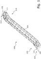
- FIG. 1 a part of a preferred embodiment of a conveying device according to the invention is shown schematically and denoted by 100.
- the conveying device 100 is designed as an escalator.
- the escalator 100 has a carrier 101.
- This carrier 101 is designed, for example, as a truss construction from a multiplicity of, for example, longitudinal, vertical and / or diagonal struts.
- a conveyor belt in the form of a step belt and elements for moving it can be arranged in the carrier 101.
- the escalator 100 can also have further elements, which are shown in FIG Figure 1 for the sake of clarity are also not shown, for example handrails, drives for moving the handrails, shafts, gears, gears, chains, other rails, etc.
- the carrier 101 has a first or upper end 110 and a second or lower end 120. Elements are provided at the ends 110 and 120 in order to attach the escalator 100 to a building.
- a first support 102 and a second support 103 of this building are shown. These supports are in particular firmly connected to the building or are designed as part of the building.
- the escalator 100 is attached to these supports 102 and 103 and thus to the building.
- the supports 102 and 103 are formed, for example, from concrete.
- a first or upper support bracket 111 is attached to the carrier 101 at the upper end 110. This first support bracket 111 is attached to the first support 102 via a fixed bearing 112. A second or lower support bracket 121 is attached to the second end 120 of the carrier 101. This second support bracket 121 is attached to the second support 103 via a floating bearing 122.
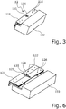
- the upper end 110 of the carrier 101 is in the Figures 2 and 3 each shown schematically in a perspective view and in Figure 4 in a schematic top view.
- the first support bracket 111 can be firmly connected to the support 101, support bracket 111 and support 101 can form a common structural unit.
- the first support bracket 111 and the carrier 101 can also be separate components; the first support bracket 111 can be screwed to the carrier 101, for example.
- the first support bracket 111 has a hole 113 for the fixed bearing 112.
- a first fastening element 114 is inserted into this hole 113 or the first fastening element 114 penetrates the hole 113.
- the first fastening element 114 is designed as a pin.
- the pin 114 is non-positively connected to the first support 102.
- a first securing element 115 is attached to the pin 114.
- the first securing element 115 is designed in particular as a first disk which is screwed onto the pin 114, for example.
- the diameter of the hole 113 essentially corresponds to the diameter of the pin 114.
- the hole 113 can be a maximum of 0.5% larger than the diameter of the pin 114. The pin 114 can thus be easily inserted through the hole 113.
- the first support bracket 111 rests on elements 116 which are firmly connected to the first support 102.
- These elements 116 are designed, for example, as threaded bolts which are screwed into the first support 102.
- the fixed bearing 112 prevents a translational movement of the first support bracket 111 with respect to the support 102.
- a rotational movement of the first support bracket 111 and thus of the carrier 101 about the pin 114 is possible within the limits defined, for example, by the first support 102
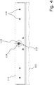
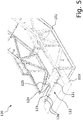
- the second, lower end 120 of the carrier 101 is in the Figures 5 and 6th each shown schematically in a perspective view and in Figure 7 in a schematic plan view.
- the second support bracket 121 can also be firmly connected to the carrier 101 or fastened to it, for example screwed on.
- the second support bracket 121 has an elongated hole 123 for the floating bearing 122.
- the main direction of extent of the elongated hole 123 corresponds to the main direction of extent of the escalator 100.
- a second fastening element 124 in the form of a pin penetrates the elongated hole 123.
- the pin 124 is connected to the second support 103 with a force fit.
- a second securing element 125 in the form of a washer is applied, for example screwed, to the pin 124.
- the width of the elongated hole 123 essentially corresponds to the diameter of the pin 124.
- the width of the elongated hole 123 can be a maximum of 0.5% greater than the diameter of the pin 124. The pin 124 can thus be easily inserted through the elongated hole 123.
- the length of the elongated hole 123 is 140 mm longer than the diameter of the pin 124. This enables a translational movement of the second support bracket 121 relative to the second support 103 in a range between ⁇ 70 mm in the direction of the main direction of extension of the escalator 100 .
- the second support bracket 121 also rests on elements 126 in the form of threaded bolts, which are firmly connected to the second support 103.
- the floating bearing 122 causes a translational movement of the second support bracket 121 in the direction of the main direction of extent of the escalator 100 in a range between ⁇ 70 mm. Furthermore, a rotational movement of the second support bracket 121 and thus of the carrier 101 around the pin 124 is possible.
- escalator 100 In the event of a natural disaster, for example an earthquake, forces that occur as a result of the natural disaster and act on escalator 100 can be compensated within certain limits. Since the escalator 100 is not rigidly fastened in the building, compression, stretching or twisting or shearing movements of the building, in particular e.g. the supports 102 and 103 relative to one another, are ideally not transmitted to the carrier 101. It is thus possible, up to a certain degree of severity of the natural disaster, to prevent the forces occurring in the carrier 101 from creating tension and from being damaged. In particular, breaking of individual struts of the carrier 101 can be prevented better than in the case of conventional escalators.
- the supports 102 and 103 can move apart in the main direction of extent of the escalator 100 or move towards one another. By preventing translational movements of the first support bracket 111, this is “held in place” in such a case and the escalator 100 executes the analog movement of the first support 102. Due to the possible translational movement of the second support bracket 121 in the direction of the main direction of extent, the escalator 100 can move relative to the second support 103.
- the supports 102 and 103 can also rotate about a common axis of rotation or about different axes of rotation perpendicular to the main direction of extent of the escalator. Due to the possible rotation of the support brackets 111 and 121 around the respective pin 114 and 124, the escalator 100 can in such a case rotate around the corresponding axis of rotation perpendicular to the main direction of extent, analogously to the supports 102 and 103.
Claims (13)
- Dispositif de transport (100), en particulier escalier mécanique ou tapis roulant, comprenant un support (101), un premier coin d'appui (111) étant monté à une première extrémité (110) du support (101) et un deuxième coin d'appui (121) étant monté à une deuxième extrémité (120) du support (101) ,
le premier coin d'appui (111) étant monté sur un bâtiment par le biais d'un palier fixe (112), le premier coin d'appui (111) présentant un trou (113), un premier élément de fixation (114) fixé au bâtiment traversant le trou (113),
caractérisé en ce que
le deuxième coin d'appui (121) est monté sur le bâtiment par le biais d'un palier fou (122), le deuxième coin d'appui (121) présentant un trou oblong (123) et un deuxième élément de fixation (124) fixé au bâtiment traversant le trou oblong (123) . - Dispositif de transport (100) selon la revendication 1, dans lequel un premier élément de sécurisation (115) est monté sur le premier élément de fixation (114) et/ou dans lequel un deuxième élément de sécurisation (125) est monté sur le deuxième élément de fixation (124).
- Dispositif de transport (100) selon la revendication 2, dans lequel le premier élément de sécurisation (115) et/ou le deuxième élément de sécurisation (125) sont à chaque fois réalisés sous forme de disque, d'écrou, de bague de fixation ou de goupille fendue.
- Dispositif de transport (100) selon la revendication 3, dans lequel le premier élément de sécurisation (115) est réalisé sous la forme d'un premier disque dont la largeur est supérieure à la largeur du trou (112) du premier coin d'appui (111) et/ou dans lequel le deuxième élément de sécurisation (125) est réalisé sous la forme d'un deuxième disque dont la largeur est supérieure à la largeur du trou oblong (123).
- Dispositif de transport (100) selon l'une quelconque des revendications 2 à 4, dans lequel le premier élément de sécurisation (115) et le premier élément de fixation (114) et/ou le deuxième élément de sécurisation (125) et le deuxième élément de fixation (124) forment à chaque fois une unité structurelle.
- Dispositif de transport (100) selon l'une quelconque des revendications précédentes, dans lequel le premier élément de fixation (114) et/ou le deuxième élément de fixation (124) sont réalisés sous forme de goupille et/ou de boulon fileté.
- Dispositif de transport (100) selon l'une quelconque des revendications précédentes, dans lequel le premier élément de fixation (114) et le deuxième élément de fixation (124) sont réalisés essentiellement sous forme cylindrique et/ou le trou (112) du premier coin d'appui (111) est réalisé essentiellement sous forme circulaire.
- Dispositif de transport (100) selon la revendication 7, dans lequel le trou (113) du premier coin d'appui (111) possède essentiellement le même diamètre que le premier élément de fixation (114).
- Dispositif de transport (100) selon la revendication 7 ou 8, dans lequel la largeur du trou oblong (123) correspond essentiellement au diamètre du deuxième élément de fixation (124).
- Dispositif de transport (100) selon l'une quelconque des revendications 7 à 9, dans lequel la longueur du trou oblong (123) est plus longue de 100 mm à 350 mm que le diamètre du deuxième élément de fixation (124), en particulier est plus longue de 140 mm à 280 mm que le diamètre du deuxième élément de fixation (124).
- Dispositif de transport (100) selon l'une quelconque des revendications précédentes, dans lequel le premier coin d'appui (111) est monté à une extrémité supérieure (110) du support (101) et le deuxième coin d'appui (121) est monté à une extrémité inférieure (120) du support (101).
- Procédé d'installation d'un dispositif de transport (100), en particulier d'un escalier mécanique ou d'un tapis roulant, dans un bâtiment, un premier coin d'appui (111) monté à une première extrémité (110) d'un support (101) du dispositif de transport (100) étant monté sur le bâtiment par le biais d'un palier fixe (112),
un premier élément de fixation (114) étant introduit à travers un trou (113) dans le premier coin d'appui (111) et étant fixé au bâtiment, caractérisé en ce
qu'un deuxième coin d'appui (121) monté à une deuxième extrémité (120) du support (101) du dispositif de transport (100) est monté sur le bâtiment par le biais d'un palier fou (122), et en ce qu'un deuxième élément de fixation (124) est introduit à travers un trou oblong (123) dans le deuxième coin d'appui (121) et est fixé au bâtiment. - Procédé selon la revendication 12,
dans lequel le premier coin d'appui (111) monté à une extrémité supérieure (110) du support (101) du dispositif de transport (100) est monté par le biais du palier fixe (112) à un étage supérieur du bâtiment,
et dans lequel le deuxième coin d'appui (121) monté à une extrémité inférieure (120) du support (101) du dispositif de transport (100) est monté par le biais d'un palier fou (122) à un étage inférieur du bâtiment.
Applications Claiming Priority (2)
| Application Number | Priority Date | Filing Date | Title |
|---|---|---|---|
| DE102015214077.6A DE102015214077A1 (de) | 2015-07-24 | 2015-07-24 | Beförderungsvorrichtung, insbesondere Fahrtreppe oder Fahrsteig |
| PCT/EP2016/067509 WO2017017005A1 (fr) | 2015-07-24 | 2016-07-22 | Dispositif de transport, en particulier escalier mécanique ou trottoir roulant |
Publications (3)
| Publication Number | Publication Date |
|---|---|
| EP3325397A1 EP3325397A1 (fr) | 2018-05-30 |
| EP3325397B1 true EP3325397B1 (fr) | 2021-05-05 |
| EP3325397B8 EP3325397B8 (fr) | 2021-06-09 |
Family
ID=56497787
Family Applications (1)
| Application Number | Title | Priority Date | Filing Date |
|---|---|---|---|
| EP16741337.6A Active EP3325397B8 (fr) | 2015-07-24 | 2016-07-22 | Dispositif de transport, en particulier escalier mécanique ou trottoir roulant |
Country Status (6)
| Country | Link |
|---|---|
| US (1) | US10364129B2 (fr) |
| EP (1) | EP3325397B8 (fr) |
| CN (1) | CN107848769B (fr) |
| DE (1) | DE102015214077A1 (fr) |
| HK (1) | HK1251541A1 (fr) |
| WO (1) | WO2017017005A1 (fr) |
Families Citing this family (5)
| Publication number | Priority date | Publication date | Assignee | Title |
|---|---|---|---|---|
| DE102015224549A1 (de) * | 2015-12-08 | 2017-06-08 | Thyssenkrupp Ag | Fahrtreppen- oder Fahrsteigtragekonstruktion sowie Verfahren zur Fertigung zumindest eines Teilsegments einer Fahrtreppen- oder Fahrsteigtragekonstruktion |
| ES2773514T3 (es) * | 2015-12-17 | 2020-07-13 | Inventio Ag | Revestimiento de suelo de una instalación de transporte de personas |
| US10421643B2 (en) * | 2016-01-21 | 2019-09-24 | Mitsubishi Electric Corporation | Passenger conveyor |
| WO2019102542A1 (fr) * | 2017-11-22 | 2019-05-31 | 三菱電機株式会社 | Trottoir roulant |
| CN109081230A (zh) * | 2018-10-31 | 2018-12-25 | 通力电梯有限公司 | 位于自动扶梯和建筑物之间的界面结构及自动扶梯 |
Family Cites Families (16)
| Publication number | Priority date | Publication date | Assignee | Title |
|---|---|---|---|---|
| JPS4935113Y1 (fr) * | 1970-11-30 | 1974-09-24 | ||
| JPS526389U (fr) * | 1975-06-27 | 1977-01-17 | ||
| JP3473206B2 (ja) | 1995-08-29 | 2003-12-02 | 三菱電機株式会社 | マンコンベアの脱落抑制装置 |
| CN1187256C (zh) * | 1998-06-11 | 2005-02-02 | 因温特奥股份公司 | 电梯或移动通道 |
| EP0963941B1 (fr) * | 1998-06-11 | 2003-08-20 | Inventio Ag | Appui pour escalier roulant ou tapis roulant |
| DE50103782D1 (de) * | 2000-07-27 | 2004-10-28 | Inventio Ag | Erdbebensicheres auflager für fahrtreppe oder fahrsteig |
| US6637580B1 (en) * | 2002-12-05 | 2003-10-28 | Terryle L. Sneed | Telescoping escalator seismic restraint |
| US7740235B2 (en) | 2005-03-08 | 2010-06-22 | Inventio Ag | Mount for equipment for conveying persons |
| JP2011063389A (ja) * | 2009-09-17 | 2011-03-31 | Mitsubishi Electric Corp | 乗客コンベアのトラス支持装置 |
| JP2012086939A (ja) * | 2010-10-19 | 2012-05-10 | Ohbayashi Corp | 通路設備 |
| JP2013241227A (ja) * | 2012-05-17 | 2013-12-05 | Toshiba Elevator Co Ltd | エスカレータ |
| US9254986B2 (en) * | 2012-06-21 | 2016-02-09 | Mitsubishi Electric Corporation | Passenger conveyor |
| JP6182418B2 (ja) * | 2013-10-15 | 2017-08-16 | 株式会社日立製作所 | 乗客コンベア |
| WO2015082195A1 (fr) * | 2013-12-06 | 2015-06-11 | Inventio Ag | Support permettant le montage sur un chantier d'un dispositif de transport de personnes |
| CN107922167B (zh) * | 2015-08-11 | 2019-07-05 | 三菱电机株式会社 | 乘客输送机的桁架支撑装置 |
| US10421643B2 (en) * | 2016-01-21 | 2019-09-24 | Mitsubishi Electric Corporation | Passenger conveyor |
-
2015
- 2015-07-24 DE DE102015214077.6A patent/DE102015214077A1/de not_active Ceased
-
2016
- 2016-07-22 CN CN201680043444.0A patent/CN107848769B/zh active Active
- 2016-07-22 US US15/745,785 patent/US10364129B2/en not_active Expired - Fee Related
- 2016-07-22 WO PCT/EP2016/067509 patent/WO2017017005A1/fr active Application Filing
- 2016-07-22 EP EP16741337.6A patent/EP3325397B8/fr active Active
-
2018
- 2018-08-27 HK HK18110991.8A patent/HK1251541A1/zh unknown
Non-Patent Citations (1)
| Title |
|---|
| None * |
Also Published As
| Publication number | Publication date |
|---|---|
| EP3325397B8 (fr) | 2021-06-09 |
| WO2017017005A1 (fr) | 2017-02-02 |
| CN107848769B (zh) | 2023-02-24 |
| DE102015214077A1 (de) | 2017-01-26 |
| US10364129B2 (en) | 2019-07-30 |
| US20180208440A1 (en) | 2018-07-26 |
| HK1251541A1 (zh) | 2019-02-01 |
| CN107848769A (zh) | 2018-03-27 |
| EP3325397A1 (fr) | 2018-05-30 |
Similar Documents
| Publication | Publication Date | Title |
|---|---|---|
| EP3325397B1 (fr) | Dispositif de transport, en particulier escalier mécanique ou trottoir roulant | |
| EP1797258B1 (fr) | Construction d'appui stabilisée | |
| EP3077321B1 (fr) | Appui pour le logement côté construction d'un dispositif de transport de personnes | |
| EP3896240A1 (fr) | Échafaudage | |
| DE102006011336A1 (de) | Bauelement zur Wärmedämmung | |
| EP1303455B1 (fr) | Structure porteuse resistante aux tremblements de terre pour escalators ou trottoirs roulants | |
| EP2784238B1 (fr) | Traverse et procédé de montage | |
| AT13023U1 (de) | Auflastgehaltene anschlagvorrichtung | |
| DE102010006560A1 (de) | Tragvorrichtung und Schalungssystem | |
| EP2666931A2 (fr) | Système de fixation pour maintenir et sécuriser au moins une personne | |
| DE102018102637A1 (de) | Schutzgerüst, insbesondere Freileitungsschutzgerüst sowie Verfahren zum Errichten eines Schutzgerüstes | |
| EP3564441B1 (fr) | Bâti de protection contre les avalanches, les éboulements rocheux et les glissements de terrain | |
| DE202021101575U1 (de) | Verbessertes Schutzgerüst | |
| DE102011120071A1 (de) | Fahrbare Lagereinrichtung für eine mobile Dachkonstruktion | |
| AT522691B1 (de) | Gründung für ein Gebäude | |
| EP1288392B1 (fr) | Structure de support pour un système porteur d'une structure d'estrade, de podium, d'échafaudage ou similaire | |
| DE102010025667B4 (de) | Hochseilgarten | |
| DE3107484C2 (de) | Kabelträgersystem | |
| AT519616B1 (de) | Wange für eine treppe, eine brücke, einen laufsteg oder dergleichen sowie treppe, brücke, laufsteg oder dergleichen mit einer derartigen wange | |
| DE202016106507U1 (de) | Gerüst | |
| EP3259455B1 (fr) | Systeme de levage et de transport de charge lourdes | |
| EP4064485A1 (fr) | Échafaudage à protection améliorée | |
| EP1589234B1 (fr) | Dispositif de fixation | |
| DE202023105463U1 (de) | Mast zur Befestigung einer Nutzlast | |
| WO2018130335A1 (fr) | Système de convoyage aérien comprenant un convoyeur disposé verticalement |
Legal Events
| Date | Code | Title | Description |
|---|---|---|---|
| STAA | Information on the status of an ep patent application or granted ep patent |
Free format text: STATUS: THE INTERNATIONAL PUBLICATION HAS BEEN MADE |
|
| PUAI | Public reference made under article 153(3) epc to a published international application that has entered the european phase |
Free format text: ORIGINAL CODE: 0009012 |
|
| STAA | Information on the status of an ep patent application or granted ep patent |
Free format text: STATUS: REQUEST FOR EXAMINATION WAS MADE |
|
| 17P | Request for examination filed |
Effective date: 20180110 |
|
| AK | Designated contracting states |
Kind code of ref document: A1 Designated state(s): AL AT BE BG CH CY CZ DE DK EE ES FI FR GB GR HR HU IE IS IT LI LT LU LV MC MK MT NL NO PL PT RO RS SE SI SK SM TR |
|
| AX | Request for extension of the european patent |
Extension state: BA ME |
|
| RAP1 | Party data changed (applicant data changed or rights of an application transferred) |
Owner name: THYSSENKRUPP ELEVATOR AG Owner name: THYSSENKRUPP AG |
|
| DAV | Request for validation of the european patent (deleted) | ||
| DAX | Request for extension of the european patent (deleted) | ||
| STAA | Information on the status of an ep patent application or granted ep patent |
Free format text: STATUS: EXAMINATION IS IN PROGRESS |
|
| 17Q | First examination report despatched |
Effective date: 20200317 |
|
| RAP1 | Party data changed (applicant data changed or rights of an application transferred) |
Owner name: THYSSENKRUPP ELEVATOR INNOVATION AND OPERATIONS AG |
|
| GRAP | Despatch of communication of intention to grant a patent |
Free format text: ORIGINAL CODE: EPIDOSNIGR1 |
|
| STAA | Information on the status of an ep patent application or granted ep patent |
Free format text: STATUS: GRANT OF PATENT IS INTENDED |
|
| INTG | Intention to grant announced |
Effective date: 20201202 |
|
| GRAS | Grant fee paid |
Free format text: ORIGINAL CODE: EPIDOSNIGR3 |
|
| GRAA | (expected) grant |
Free format text: ORIGINAL CODE: 0009210 |
|
| STAA | Information on the status of an ep patent application or granted ep patent |
Free format text: STATUS: THE PATENT HAS BEEN GRANTED |
|
| AK | Designated contracting states |
Kind code of ref document: B1 Designated state(s): AL AT BE BG CH CY CZ DE DK EE ES FI FR GB GR HR HU IE IS IT LI LT LU LV MC MK MT NL NO PL PT RO RS SE SI SK SM TR |
|
| REG | Reference to a national code |
Ref country code: GB Ref legal event code: FG4D Free format text: NOT ENGLISH |
|
| REG | Reference to a national code |
Ref country code: CH Ref legal event code: EP Ref country code: CH Ref legal event code: PK Free format text: BERICHTIGUNG B8 |
|
| REG | Reference to a national code |
Ref country code: AT Ref legal event code: REF Ref document number: 1389601 Country of ref document: AT Kind code of ref document: T Effective date: 20210515 |
|
| REG | Reference to a national code |
Ref country code: IE Ref legal event code: FG4D Free format text: LANGUAGE OF EP DOCUMENT: GERMAN |
|
| REG | Reference to a national code |
Ref country code: DE Ref legal event code: R096 Ref document number: 502016012989 Country of ref document: DE |
|
| RAP4 | Party data changed (patent owner data changed or rights of a patent transferred) |
Owner name: TK ELEVATOR INNOVATION AND OPERATIONS GMBH |
|
| REG | Reference to a national code |
Ref country code: LT Ref legal event code: MG9D |
|
| PG25 | Lapsed in a contracting state [announced via postgrant information from national office to epo] |
Ref country code: LT Free format text: LAPSE BECAUSE OF FAILURE TO SUBMIT A TRANSLATION OF THE DESCRIPTION OR TO PAY THE FEE WITHIN THE PRESCRIBED TIME-LIMIT Effective date: 20210505 Ref country code: FI Free format text: LAPSE BECAUSE OF FAILURE TO SUBMIT A TRANSLATION OF THE DESCRIPTION OR TO PAY THE FEE WITHIN THE PRESCRIBED TIME-LIMIT Effective date: 20210505 Ref country code: HR Free format text: LAPSE BECAUSE OF FAILURE TO SUBMIT A TRANSLATION OF THE DESCRIPTION OR TO PAY THE FEE WITHIN THE PRESCRIBED TIME-LIMIT Effective date: 20210505 Ref country code: BG Free format text: LAPSE BECAUSE OF FAILURE TO SUBMIT A TRANSLATION OF THE DESCRIPTION OR TO PAY THE FEE WITHIN THE PRESCRIBED TIME-LIMIT Effective date: 20210805 |
|
| PG25 | Lapsed in a contracting state [announced via postgrant information from national office to epo] |
Ref country code: NO Free format text: LAPSE BECAUSE OF FAILURE TO SUBMIT A TRANSLATION OF THE DESCRIPTION OR TO PAY THE FEE WITHIN THE PRESCRIBED TIME-LIMIT Effective date: 20210805 Ref country code: PT Free format text: LAPSE BECAUSE OF FAILURE TO SUBMIT A TRANSLATION OF THE DESCRIPTION OR TO PAY THE FEE WITHIN THE PRESCRIBED TIME-LIMIT Effective date: 20210906 Ref country code: PL Free format text: LAPSE BECAUSE OF FAILURE TO SUBMIT A TRANSLATION OF THE DESCRIPTION OR TO PAY THE FEE WITHIN THE PRESCRIBED TIME-LIMIT Effective date: 20210505 Ref country code: RS Free format text: LAPSE BECAUSE OF FAILURE TO SUBMIT A TRANSLATION OF THE DESCRIPTION OR TO PAY THE FEE WITHIN THE PRESCRIBED TIME-LIMIT Effective date: 20210505 Ref country code: SE Free format text: LAPSE BECAUSE OF FAILURE TO SUBMIT A TRANSLATION OF THE DESCRIPTION OR TO PAY THE FEE WITHIN THE PRESCRIBED TIME-LIMIT Effective date: 20210505 Ref country code: IS Free format text: LAPSE BECAUSE OF FAILURE TO SUBMIT A TRANSLATION OF THE DESCRIPTION OR TO PAY THE FEE WITHIN THE PRESCRIBED TIME-LIMIT Effective date: 20210905 Ref country code: LV Free format text: LAPSE BECAUSE OF FAILURE TO SUBMIT A TRANSLATION OF THE DESCRIPTION OR TO PAY THE FEE WITHIN THE PRESCRIBED TIME-LIMIT Effective date: 20210505 Ref country code: GR Free format text: LAPSE BECAUSE OF FAILURE TO SUBMIT A TRANSLATION OF THE DESCRIPTION OR TO PAY THE FEE WITHIN THE PRESCRIBED TIME-LIMIT Effective date: 20210806 |
|
| REG | Reference to a national code |
Ref country code: NL Ref legal event code: MP Effective date: 20210505 |
|
| PG25 | Lapsed in a contracting state [announced via postgrant information from national office to epo] |
Ref country code: NL Free format text: LAPSE BECAUSE OF FAILURE TO SUBMIT A TRANSLATION OF THE DESCRIPTION OR TO PAY THE FEE WITHIN THE PRESCRIBED TIME-LIMIT Effective date: 20210505 |
|
| PG25 | Lapsed in a contracting state [announced via postgrant information from national office to epo] |
Ref country code: ES Free format text: LAPSE BECAUSE OF FAILURE TO SUBMIT A TRANSLATION OF THE DESCRIPTION OR TO PAY THE FEE WITHIN THE PRESCRIBED TIME-LIMIT Effective date: 20210505 Ref country code: RO Free format text: LAPSE BECAUSE OF FAILURE TO SUBMIT A TRANSLATION OF THE DESCRIPTION OR TO PAY THE FEE WITHIN THE PRESCRIBED TIME-LIMIT Effective date: 20210505 Ref country code: DK Free format text: LAPSE BECAUSE OF FAILURE TO SUBMIT A TRANSLATION OF THE DESCRIPTION OR TO PAY THE FEE WITHIN THE PRESCRIBED TIME-LIMIT Effective date: 20210505 Ref country code: CZ Free format text: LAPSE BECAUSE OF FAILURE TO SUBMIT A TRANSLATION OF THE DESCRIPTION OR TO PAY THE FEE WITHIN THE PRESCRIBED TIME-LIMIT Effective date: 20210505 Ref country code: EE Free format text: LAPSE BECAUSE OF FAILURE TO SUBMIT A TRANSLATION OF THE DESCRIPTION OR TO PAY THE FEE WITHIN THE PRESCRIBED TIME-LIMIT Effective date: 20210505 Ref country code: SM Free format text: LAPSE BECAUSE OF FAILURE TO SUBMIT A TRANSLATION OF THE DESCRIPTION OR TO PAY THE FEE WITHIN THE PRESCRIBED TIME-LIMIT Effective date: 20210505 Ref country code: SK Free format text: LAPSE BECAUSE OF FAILURE TO SUBMIT A TRANSLATION OF THE DESCRIPTION OR TO PAY THE FEE WITHIN THE PRESCRIBED TIME-LIMIT Effective date: 20210505 |
|
| REG | Reference to a national code |
Ref country code: DE Ref legal event code: R119 Ref document number: 502016012989 Country of ref document: DE |
|
| REG | Reference to a national code |
Ref country code: CH Ref legal event code: PL |
|
| PLBE | No opposition filed within time limit |
Free format text: ORIGINAL CODE: 0009261 |
|
| STAA | Information on the status of an ep patent application or granted ep patent |
Free format text: STATUS: NO OPPOSITION FILED WITHIN TIME LIMIT |
|
| PG25 | Lapsed in a contracting state [announced via postgrant information from national office to epo] |
Ref country code: MC Free format text: LAPSE BECAUSE OF FAILURE TO SUBMIT A TRANSLATION OF THE DESCRIPTION OR TO PAY THE FEE WITHIN THE PRESCRIBED TIME-LIMIT Effective date: 20210505 |
|
| REG | Reference to a national code |
Ref country code: BE Ref legal event code: MM Effective date: 20210731 |
|
| 26N | No opposition filed |
Effective date: 20220208 |
|
| GBPC | Gb: european patent ceased through non-payment of renewal fee |
Effective date: 20210805 |
|
| PG25 | Lapsed in a contracting state [announced via postgrant information from national office to epo] |
Ref country code: LI Free format text: LAPSE BECAUSE OF NON-PAYMENT OF DUE FEES Effective date: 20210731 Ref country code: DE Free format text: LAPSE BECAUSE OF NON-PAYMENT OF DUE FEES Effective date: 20220201 Ref country code: CH Free format text: LAPSE BECAUSE OF NON-PAYMENT OF DUE FEES Effective date: 20210731 |
|
| PG25 | Lapsed in a contracting state [announced via postgrant information from national office to epo] |
Ref country code: IS Free format text: LAPSE BECAUSE OF FAILURE TO SUBMIT A TRANSLATION OF THE DESCRIPTION OR TO PAY THE FEE WITHIN THE PRESCRIBED TIME-LIMIT Effective date: 20210905 Ref country code: LU Free format text: LAPSE BECAUSE OF NON-PAYMENT OF DUE FEES Effective date: 20210722 Ref country code: FR Free format text: LAPSE BECAUSE OF NON-PAYMENT OF DUE FEES Effective date: 20210731 Ref country code: AL Free format text: LAPSE BECAUSE OF FAILURE TO SUBMIT A TRANSLATION OF THE DESCRIPTION OR TO PAY THE FEE WITHIN THE PRESCRIBED TIME-LIMIT Effective date: 20210505 |
|
| PG25 | Lapsed in a contracting state [announced via postgrant information from national office to epo] |
Ref country code: IE Free format text: LAPSE BECAUSE OF NON-PAYMENT OF DUE FEES Effective date: 20210722 Ref country code: GB Free format text: LAPSE BECAUSE OF NON-PAYMENT OF DUE FEES Effective date: 20210805 Ref country code: BE Free format text: LAPSE BECAUSE OF NON-PAYMENT OF DUE FEES Effective date: 20210731 |
|
| REG | Reference to a national code |
Ref country code: AT Ref legal event code: MM01 Ref document number: 1389601 Country of ref document: AT Kind code of ref document: T Effective date: 20210722 |
|
| PG25 | Lapsed in a contracting state [announced via postgrant information from national office to epo] |
Ref country code: AT Free format text: LAPSE BECAUSE OF NON-PAYMENT OF DUE FEES Effective date: 20210722 |
|
| PG25 | Lapsed in a contracting state [announced via postgrant information from national office to epo] |
Ref country code: HU Free format text: LAPSE BECAUSE OF FAILURE TO SUBMIT A TRANSLATION OF THE DESCRIPTION OR TO PAY THE FEE WITHIN THE PRESCRIBED TIME-LIMIT; INVALID AB INITIO Effective date: 20160722 |
|
| PG25 | Lapsed in a contracting state [announced via postgrant information from national office to epo] |
Ref country code: CY Free format text: LAPSE BECAUSE OF FAILURE TO SUBMIT A TRANSLATION OF THE DESCRIPTION OR TO PAY THE FEE WITHIN THE PRESCRIBED TIME-LIMIT Effective date: 20210505 |
|
| PGFP | Annual fee paid to national office [announced via postgrant information from national office to epo] |
Ref country code: TR Payment date: 20230721 Year of fee payment: 8 Ref country code: IT Payment date: 20230724 Year of fee payment: 8 |