EP3325397B1 - Transporting apparatus, in particular escalator or moving walkway - Google Patents
Transporting apparatus, in particular escalator or moving walkway Download PDFInfo
- Publication number
- EP3325397B1 EP3325397B1 EP16741337.6A EP16741337A EP3325397B1 EP 3325397 B1 EP3325397 B1 EP 3325397B1 EP 16741337 A EP16741337 A EP 16741337A EP 3325397 B1 EP3325397 B1 EP 3325397B1
- Authority
- EP
- European Patent Office
- Prior art keywords
- fastening element
- support
- fitted
- transporting apparatus
- building
- Prior art date
- Legal status (The legal status is an assumption and is not a legal conclusion. Google has not performed a legal analysis and makes no representation as to the accuracy of the status listed.)
- Active
Links
Images


Classifications
-
- B—PERFORMING OPERATIONS; TRANSPORTING
- B66—HOISTING; LIFTING; HAULING
- B66B—ELEVATORS; ESCALATORS OR MOVING WALKWAYS
- B66B23/00—Component parts of escalators or moving walkways
-
- B—PERFORMING OPERATIONS; TRANSPORTING
- B66—HOISTING; LIFTING; HAULING
- B66B—ELEVATORS; ESCALATORS OR MOVING WALKWAYS
- B66B21/00—Kinds or types of escalators or moving walkways
- B66B21/02—Escalators
- B66B21/04—Escalators linear type
-
- B—PERFORMING OPERATIONS; TRANSPORTING
- B66—HOISTING; LIFTING; HAULING
- B66B—ELEVATORS; ESCALATORS OR MOVING WALKWAYS
- B66B29/00—Safety devices of escalators or moving walkways
-
- B—PERFORMING OPERATIONS; TRANSPORTING
- B66—HOISTING; LIFTING; HAULING
- B66B—ELEVATORS; ESCALATORS OR MOVING WALKWAYS
- B66B21/00—Kinds or types of escalators or moving walkways
- B66B21/10—Moving walkways
Definitions
- the present invention relates to a conveying device, in particular an escalator or a moving walk, with a carrier and a method for installing a conveying device in a building.
- Conveyor devices for example escalators or moving walks, mostly have a conveyor belt in the form of a step belt or a conveyor belt.
- This conveyor belt is mostly arranged within a carrier or frame of the conveyor device.
- This carrier mostly has elements in order to arrange the conveying device in a building.
- an earthquake-proof support for escalators or moving walks is disclosed.
- Supports are provided for the on-site storage of a girder at the ends of the escalator or moving walk.
- JP S52 6389 U a conveying device is disclosed, the carrier of which is arranged on a building via two fixed bearings. Additionally disclosed JP S52 6389 U the preamble of claims 1 and 12.
- the conveying device is designed in particular as an escalator or as a moving walkway, further in particular as a passenger conveying device.
- a first support bracket is attached to a first end of a carrier or frame of the conveying device.
- a second support bracket is attached to a second end of the beam.
- the support brackets are intended in particular to support the support on a building.
- the first support bracket is attached to the building via a fixed bearing.
- the first support bracket has a hole.
- a first fastener attached to the building penetrates the hole.
- the second support bracket is attached to the building via a floating bearing.
- the second support bracket has an elongated hole.
- a second fastening element fastened to the building penetrates the elongated hole.
- the main direction of extent of the elongated hole runs in particular parallel to the main direction of extent of the conveying device.
- an appropriate support is provided on the building, to which the respective support bracket is attached.
- These supports can be made of concrete, hardwood and / or hard rubber, for example.
- the first or the second fastening element is in particular fastened to the respective support.
- the conveying device has, in particular, a conveying belt, in particular an endlessly revolving, movable conveying belt.
- the conveyor belt is designed, in particular, as a step belt and, in the case of a moving walk, in particular as a conveyor belt.
- the conveyor may have other useful elements, for example a balustrade, handrails, drives for moving the conveyor belt and handrails, shafts, gears, gears, chains, rails, etc.
- the carrier represents a carrier structure in which different elements of the conveyor device are arranged, for example the conveyor belt and elements for moving it.
- the carrier is designed, for example, as a framework structure and is composed of a large number of longitudinal, vertical and / or diagonal struts or beams, which can be made of metal or steel.
- the first support bracket is mounted on the building via the fixed bearing in such a way that a translational movement of the first support bracket is prevented in all three spatial directions and that a rotary movement, in particular around a vertical axis or around a main direction of extent of the building, is enabled.
- the second support bracket is in particular mounted on the building via the floating bearing in such a way that a translational movement of the second support bracket in one of the three spatial directions is made possible, at least to a certain extent.
- a translational movement along a main direction of extent of the conveying device or along a direction of movement of the conveyor belt is made possible via the floating bearing.
- the floating bearing also enables, in particular, a rotational movement around the main direction of extent of the building.
- the conveyor is secured against damage caused by natural disasters such as earthquakes or hurricanes.
- the transport device is particularly suitable for use in buildings in earthquake-prone areas or in areas with strong seismic activities and is protected against damage from earthquakes or seismic activities.
- high forces, loads and accelerations can act on the conveying device.
- the fixed bearing ensures that the transport device is not undesirably set in translatory motion by the forces that occur during natural disasters. Since both bearings enable rotational movements at least around the main direction of extent of the building and since the floating bearing enables translational movement in one of the three spatial directions, the conveying device can yield to the forces that occur at least to a certain extent and compensate for them.
- a first securing element is attached to the first fastening element.
- a second securing element is attached to the second fastening element.
- the respective support bracket is secured in particular against displacement in the vertical direction. In particular, can thus a translational movement of the transport device in the vertical direction or in the main direction of extent of the building can be prevented.
- the securing elements are in particular each attached to an upper end of the respective fastening element, which protrudes from the respective support bracket.
- the first or second securing element is made from the same material as the respective fastening element.
- the first or second securing element can prevent the transport device from "jumping" out of the support angles or being moved out of these by the forces occurring during natural disasters and thus falling down in the building, particularly in the event of natural disasters.
- the first securing element and / or the second securing element are preferably each designed as a washer, for example a round, square or rectangular washer, a nut, a securing ring or a split pin.
- the first securing element is designed as a first disk, the width of which is greater than the width of the hole of the first support bracket.
- the second securing element is preferably designed as a second disk, the width of which is greater than the width of the elongated hole.
- the first securing element and the first fastening element and / or the second securing element and the second fastening element preferably each form a structural unit.
- the respective securing element and the respective fastening element are manufactured in particular as one component.
- the respective securing element and the respective fastening element can preferably also be designed as separate elements.
- the first securing element is preferably applied to the first fastening element and / or the second securing element on the second fastening element.
- the respective securing element can be screwed or slipped onto the respective fastening element.
- the respective securing element can be screwed onto the respective fastening element in the form of a nut or slipped on in the form of a plate.
- the first fastening element and / or the second fastening element is advantageously designed in each case as a pin, pin or bolt and / or threaded bolt.
- a thread or dowel can be provided in the support of the building in order to fasten the fastening element designed as a threaded bolt.
- the fastening element can also be fastened to the support of the building with a force fit.
- the first fastening element and the second fastening element are essentially cylindrical.
- the hole of the first support bracket is preferably designed to be essentially circular.
- the hole of the first support bracket preferably has the same diameter as the first fastening element or essentially the same diameter as the first fastening element.
- the diameter of the hole is only insignificantly larger than the diameter of the first fastening element, for example a maximum of 0.25%, 0.5%, 1% or 5% larger than the diameter of the first fastening element.
- the first fastening element can thus be inserted through the hole in a simple manner.
- the width of the elongated hole preferably corresponds to the diameter of the second fastening element or essentially the diameter of the second fastening element.
- the width of the elongated hole is only insignificantly larger than the diameter of the second fastening element, for example a maximum of 0.25%, 0.5%, 1% or 5% larger than the diameter of the second fastening element.
- the second fastening element can thus also be inserted through the elongated hole in a simple manner.
- the length of the elongated hole is preferably between 100 mm and 350 mm longer than the diameter of the second fastening element.
- the length of the elongated hole is thus dimensioned such that a translational movement of the second support bracket is made possible in a range between ⁇ 50 mm and ⁇ 175mm, in particular if the second fastening element is arranged essentially in the center of the elongated hole, based on the length of the elongated hole .
- the length of the elongated hole is particularly preferably between 140 mm and 280 mm longer than the diameter of the second fastening element. This enables a translational movement of the second support bracket in a range between ⁇ 70 mm and ⁇ 140 mm, in particular with an essentially central arrangement of the second fastening element in the elongated hole, based on its length.
- the first support bracket is attached to an upper end of the support and the second support bracket is attached to a lower end of the support.
- the conveying device can thus be attached via the fixed bearing in particular to an upper floor of the building and via the floating bearing in particular to a lower floor of the building.
- the invention also relates to a method for installing a transport device in a building. Refinements of this method according to the invention emerge from the above description of the conveying device according to the invention in an analogous manner.
- the transport device To install the transport device, it is arranged in the desired position in the building, for example between two floors.
- the first fastener is through the hole in the first Inserted support bracket and attached to the building and the second fastening element is inserted through the elongated hole in the second support bracket and attached to the building.
- the first support bracket is attached to an upper floor of the building via the fixed bearing and the second support bracket is attached to a lower floor of the building via the floating bearing.
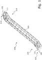
- FIG. 1 a part of a preferred embodiment of a conveying device according to the invention is shown schematically and denoted by 100.
- the conveying device 100 is designed as an escalator.
- the escalator 100 has a carrier 101.
- This carrier 101 is designed, for example, as a truss construction from a multiplicity of, for example, longitudinal, vertical and / or diagonal struts.
- a conveyor belt in the form of a step belt and elements for moving it can be arranged in the carrier 101.
- the escalator 100 can also have further elements, which are shown in FIG Figure 1 for the sake of clarity are also not shown, for example handrails, drives for moving the handrails, shafts, gears, gears, chains, other rails, etc.
- the carrier 101 has a first or upper end 110 and a second or lower end 120. Elements are provided at the ends 110 and 120 in order to attach the escalator 100 to a building.
- a first support 102 and a second support 103 of this building are shown. These supports are in particular firmly connected to the building or are designed as part of the building.
- the escalator 100 is attached to these supports 102 and 103 and thus to the building.
- the supports 102 and 103 are formed, for example, from concrete.
- a first or upper support bracket 111 is attached to the carrier 101 at the upper end 110. This first support bracket 111 is attached to the first support 102 via a fixed bearing 112. A second or lower support bracket 121 is attached to the second end 120 of the carrier 101. This second support bracket 121 is attached to the second support 103 via a floating bearing 122.
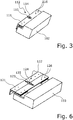
- the upper end 110 of the carrier 101 is in the Figures 2 and 3 each shown schematically in a perspective view and in Figure 4 in a schematic top view.
- the first support bracket 111 can be firmly connected to the support 101, support bracket 111 and support 101 can form a common structural unit.
- the first support bracket 111 and the carrier 101 can also be separate components; the first support bracket 111 can be screwed to the carrier 101, for example.
- the first support bracket 111 has a hole 113 for the fixed bearing 112.
- a first fastening element 114 is inserted into this hole 113 or the first fastening element 114 penetrates the hole 113.
- the first fastening element 114 is designed as a pin.
- the pin 114 is non-positively connected to the first support 102.
- a first securing element 115 is attached to the pin 114.
- the first securing element 115 is designed in particular as a first disk which is screwed onto the pin 114, for example.
- the diameter of the hole 113 essentially corresponds to the diameter of the pin 114.
- the hole 113 can be a maximum of 0.5% larger than the diameter of the pin 114. The pin 114 can thus be easily inserted through the hole 113.
- the first support bracket 111 rests on elements 116 which are firmly connected to the first support 102.
- These elements 116 are designed, for example, as threaded bolts which are screwed into the first support 102.
- the fixed bearing 112 prevents a translational movement of the first support bracket 111 with respect to the support 102.
- a rotational movement of the first support bracket 111 and thus of the carrier 101 about the pin 114 is possible within the limits defined, for example, by the first support 102
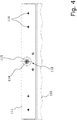
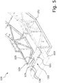
- the second, lower end 120 of the carrier 101 is in the Figures 5 and 6th each shown schematically in a perspective view and in Figure 7 in a schematic plan view.
- the second support bracket 121 can also be firmly connected to the carrier 101 or fastened to it, for example screwed on.
- the second support bracket 121 has an elongated hole 123 for the floating bearing 122.
- the main direction of extent of the elongated hole 123 corresponds to the main direction of extent of the escalator 100.
- a second fastening element 124 in the form of a pin penetrates the elongated hole 123.
- the pin 124 is connected to the second support 103 with a force fit.
- a second securing element 125 in the form of a washer is applied, for example screwed, to the pin 124.
- the width of the elongated hole 123 essentially corresponds to the diameter of the pin 124.
- the width of the elongated hole 123 can be a maximum of 0.5% greater than the diameter of the pin 124. The pin 124 can thus be easily inserted through the elongated hole 123.
- the length of the elongated hole 123 is 140 mm longer than the diameter of the pin 124. This enables a translational movement of the second support bracket 121 relative to the second support 103 in a range between ⁇ 70 mm in the direction of the main direction of extension of the escalator 100 .
- the second support bracket 121 also rests on elements 126 in the form of threaded bolts, which are firmly connected to the second support 103.
- the floating bearing 122 causes a translational movement of the second support bracket 121 in the direction of the main direction of extent of the escalator 100 in a range between ⁇ 70 mm. Furthermore, a rotational movement of the second support bracket 121 and thus of the carrier 101 around the pin 124 is possible.
- escalator 100 In the event of a natural disaster, for example an earthquake, forces that occur as a result of the natural disaster and act on escalator 100 can be compensated within certain limits. Since the escalator 100 is not rigidly fastened in the building, compression, stretching or twisting or shearing movements of the building, in particular e.g. the supports 102 and 103 relative to one another, are ideally not transmitted to the carrier 101. It is thus possible, up to a certain degree of severity of the natural disaster, to prevent the forces occurring in the carrier 101 from creating tension and from being damaged. In particular, breaking of individual struts of the carrier 101 can be prevented better than in the case of conventional escalators.
- the supports 102 and 103 can move apart in the main direction of extent of the escalator 100 or move towards one another. By preventing translational movements of the first support bracket 111, this is “held in place” in such a case and the escalator 100 executes the analog movement of the first support 102. Due to the possible translational movement of the second support bracket 121 in the direction of the main direction of extent, the escalator 100 can move relative to the second support 103.
- the supports 102 and 103 can also rotate about a common axis of rotation or about different axes of rotation perpendicular to the main direction of extent of the escalator. Due to the possible rotation of the support brackets 111 and 121 around the respective pin 114 and 124, the escalator 100 can in such a case rotate around the corresponding axis of rotation perpendicular to the main direction of extent, analogously to the supports 102 and 103.
Description
Die vorliegende Erfindung betrifft eine Beförderungsvorrichtung, insbesondere eine Fahrtreppe oder einen Fahrsteig, mit einem Träger sowie ein Verfahren zur Installation einer Beförderungsvorrichtung in einem Gebäude.The present invention relates to a conveying device, in particular an escalator or a moving walk, with a carrier and a method for installing a conveying device in a building.
Beförderungsvorrichtungen, beispielsweise Fahrtreppen oder Fahrsteige weisen zumeist ein Beförderungsband in Form eines Stufenbands oder eines Beförderungsbands auf. Dieses Beförderungsband ist zumeist innerhalb eines Trägers bzw. Gestells der Beförderungsvorrichtung angeordnet. Dieser Träger weist zumeist Elemente auf, um die Beförderungsvorrichtung in einem Gebäude anzuordnen.Conveyor devices, for example escalators or moving walks, mostly have a conveyor belt in the form of a step belt or a conveyor belt. This conveyor belt is mostly arranged within a carrier or frame of the conveyor device. This carrier mostly has elements in order to arrange the conveying device in a building.
Im Fall von Naturkatastrophen, wie z.B. Erdbeben oder Hurrikans, ist es von großer Bedeutung, dass eine Beförderungsvorrichtung sicher in dem Gebäude angeordnet ist, so dass Schäden an der Beförderungsvorrichtung durch die Naturkatastrophe oder gar ein Herunterfallen der Beförderungsvorrichtung verhindert werden kann.In the event of natural disasters, such as earthquakes or hurricanes, it is of great importance that a conveyor device is securely arranged in the building so that damage to the conveyor device by the natural disaster or even falling of the conveyor device can be prevented.
In der
Aus der
In der
In der
Es ist wünschenswert, eine Beförderungsvorrichtung bereitzustellen, welche sicher in einem Gebäude angeordnet ist, so dass diese und das Gebäude gegen Schäden durch Naturkatastrophen geschützt sind.It is desirable to provide a conveyor that is securely located in a building so that it and the building are protected from damage from natural disasters.
Erfindungsgemäß werden eine Beförderungsvorrichtung sowie ein Verfahren zur Installation einer Beförderungsvorrichtung in einem Gebäude mit den Merkmalen der unabhängigen Patentansprüche vorgeschlagen. Vorteilhafte Ausgestaltungen sind Gegenstand der Unteransprüche sowie der nachfolgenden Beschreibung.According to the invention, a transport device and a method for installing a transport device in a building are proposed with the features of the independent claims. Advantageous refinements are the subject matter of the subclaims and the description below.
Die Beförderungsvorrichtung ist insbesondere als Fahrtreppe oder als Fahrsteig ausgebildet, weiter insbesondere als Personenbeförderungsvorrichtung. An einem ersten Ende eines Trägers bzw. Gestells der Beförderungsvorrichtung ist ein erster Auflagerwinkel angebracht. An einem zweiten Ende des Trägers ist ein zweiter Auflagerwinkel angebracht. Die Auflagerwinkel sind insbesondere zur Auflage des Trägers an einem Gebäude vorgesehen.The conveying device is designed in particular as an escalator or as a moving walkway, further in particular as a passenger conveying device. A first support bracket is attached to a first end of a carrier or frame of the conveying device. A second support bracket is attached to a second end of the beam. The support brackets are intended in particular to support the support on a building.
Der erste Auflagerwinkel ist über ein Festlager an dem Gebäude angebracht. Der erste Auflagerwinkel weist ein Loch auf. Ein an dem Gebäude befestigtes erstes Befestigungselement durchdringt das Loch. Der zweite Auflagerwinkel ist über ein Loslager an dem Gebäude angebracht. Der zweite Auflagerwinkel weist ein Langloch auf. Ein an dem Gebäude befestigtes zweites Befestigungselement durchdringt das Langloch. Die Haupterstreckungsrichtung des Langlochs verläuft insbesondere parallel zu der Haupterstreckungsrichtung der Beförderungsvorrichtung.The first support bracket is attached to the building via a fixed bearing. The first support bracket has a hole. A first fastener attached to the building penetrates the hole. The second support bracket is attached to the building via a floating bearing. The second support bracket has an elongated hole. A second fastening element fastened to the building penetrates the elongated hole. The main direction of extent of the elongated hole runs in particular parallel to the main direction of extent of the conveying device.
An dem Gebäude ist insbesondere jeweils ein zweckmäßiges Auflager vorgesehen, an welchem der jeweilige Auflagerwinkel angebracht ist. Diese Auflager können beispielsweise aus Beton, Hartholz und/oder Hartgummi gefertigt sein. Das erste bzw. zweite Befestigungselement ist insbesondere an dem jeweiligen Auflager befestigt.In particular, an appropriate support is provided on the building, to which the respective support bracket is attached. These supports can be made of concrete, hardwood and / or hard rubber, for example. The first or the second fastening element is in particular fastened to the respective support.
Die Beförderungsvorrichtung weist insbesondere ein Beförderungsband auf, insbesondere ein endlos umlaufendes, bewegbares Beförderungsband. Im Falle einer Fahrtreppe ist das Beförderungsband insbesondere als Stufenband ausgebildet und im Falle eines Fahrsteigs insbesondere als ein Beförderungsband. Die Beförderungsvorrichtung kann weitere zweckmäßige Elemente aufweisen, beispielsweise eine Balustrade, Handläufe, Antriebe zum Bewegen des Beförderungsbands und der Handläufe, Wellen, Getriebe, Zahnräder, Ketten, Schienen, usw.The conveying device has, in particular, a conveying belt, in particular an endlessly revolving, movable conveying belt. In the case of an escalator, the conveyor belt is designed, in particular, as a step belt and, in the case of a moving walk, in particular as a conveyor belt. The conveyor may have other useful elements, for example a balustrade, handrails, drives for moving the conveyor belt and handrails, shafts, gears, gears, chains, rails, etc.
Der Träger stellt insbesondere eine Tragekonstruktion dar, in welchem unterschiedliche Elemente der Beförderungsvorrichtung angeordnet sind, beispielsweise das Beförderungsband sowie Elemente zu dessen Bewegung. Der Träger ist beispielsweise als Fachwerkkonstruktionen ausgebildet und aus einer Vielzahl von längsgerichteten, vertikalen und/oder diagonalen Streben oder Balken zusammengesetzt, die aus Metall bzw. Stahl gefertigt sein können.In particular, the carrier represents a carrier structure in which different elements of the conveyor device are arranged, for example the conveyor belt and elements for moving it. The carrier is designed, for example, as a framework structure and is composed of a large number of longitudinal, vertical and / or diagonal struts or beams, which can be made of metal or steel.
Der erste Auflagerwinkel ist über das Festlager insbesondere derart an dem Gebäude gelagert, dass eine translatorische Bewegung des ersten Auflagerwinkels in alle drei Raumrichtungen unterbunden ist und dass eine rotatorische Bewegung insbesondere um eine vertikale Achse bzw. um eine Haupterstreckungsrichtung des Gebäudes ermöglicht ist.The first support bracket is mounted on the building via the fixed bearing in such a way that a translational movement of the first support bracket is prevented in all three spatial directions and that a rotary movement, in particular around a vertical axis or around a main direction of extent of the building, is enabled.
Über das Loslager ist der zweite Auflagerwinkel insbesondere derart an dem Gebäude gelagert, dass eine translatorische Bewegung des zweiten Auflagerwinkels in eine der drei Raumrichtungen ermöglicht wird, zumindest bis zu einem gewissen Grad. Insbesondere wird über das Loslager eine translatorische Bewegung entlang einer Haupterstreckungsrichtung der Beförderungsvorrichtung bzw. entlang einer Bewegungsrichtung des Beförderungsbandes ermöglicht.The second support bracket is in particular mounted on the building via the floating bearing in such a way that a translational movement of the second support bracket in one of the three spatial directions is made possible, at least to a certain extent. In particular, a translational movement along a main direction of extent of the conveying device or along a direction of movement of the conveyor belt is made possible via the floating bearing.
Translatorische Bewegungen senkrecht zu dieser Haupterstreckungsrichtung der Beförderungsvorrichtung werden insbesondere unterbunden. Auch durch das Loslager wird insbesondere eine rotatorische Bewegung um die Haupterstreckungsrichtung des Gebäudes ermöglicht.Translational movements perpendicular to this main direction of extent of the conveying device are in particular prevented. The floating bearing also enables, in particular, a rotational movement around the main direction of extent of the building.
Die Beförderungsvorrichtung ist gegen Schäden durch Naturkatastrophen wie Erdbeben oder Hurrikans gesichert. Die Beförderungsvorrichtung ist besonders geeignet für den Einsatz in Gebäuden in erdbebengefährdeten Gebieten bzw. in Gebieten mit starken seismischen Aktivitäten und ist gegen Schäden durch Erdbeben bzw. seismischen Aktivitäten geschützt. Bei derartigen Naturkatastrophen können hohe Kräfte, Belastungen und Beschleunigungen auf Beförderungsvorrichtung wirken. Durch das Festlager wird gewährleistet, dass die Beförderungsvorrichtung durch die bei Naturkatastrophen auftretenden Kräfte nicht ungewünscht in translatorische Bewegung versetzt wird. Da durch beide Lager rotatorische Bewegungen zumindest um die Haupterstreckungsrichtung des Gebäudes ermöglicht werden und da durch das Loslager eine translatorische Bewegung in eine der drei Raumrichtungen ermöglicht wird, kann die Beförderungsvorrichtung zumindest bis zu einem gewissen Grad den auftretenden Kräften nachgegeben und diese kompensieren. Somit wird verhindert, dass es durch die auftretenden Kräfte in der Beförderungsvorrichtung, insbesondere in dessen Träger zu Spannungen kommt und dass die Beförderungsvorrichtung, insbesondere dessen Träger beschädigt wird. Insbesondere kann ein Brechen einzelner Streben oder Balken des Trägers verhindert werden. Weiterhin wird verhindert, dass die Beförderungsvorrichtung im Fall einer Naturkatastrophe in dem Gebäude herunterfallen kann.The conveyor is secured against damage caused by natural disasters such as earthquakes or hurricanes. The transport device is particularly suitable for use in buildings in earthquake-prone areas or in areas with strong seismic activities and is protected against damage from earthquakes or seismic activities. In the event of such natural disasters, high forces, loads and accelerations can act on the conveying device. The fixed bearing ensures that the transport device is not undesirably set in translatory motion by the forces that occur during natural disasters. Since both bearings enable rotational movements at least around the main direction of extent of the building and since the floating bearing enables translational movement in one of the three spatial directions, the conveying device can yield to the forces that occur at least to a certain extent and compensate for them. It is thus prevented that the forces occurring in the conveying device, in particular in its carrier, cause tension and that the conveying device, in particular its carrier, is damaged. In particular, breaking of individual struts or beams of the carrier can be prevented. Furthermore, it is prevented that the conveyor device can fall down in the case of a natural disaster in the building.
Gemäß einer vorteilhaften Ausgestaltung ist an dem ersten Befestigungselement ein erstes Sicherungselement angebracht. Alternativ oder zusätzlich ist an dem zweiten Befestigungselement ein zweites Sicherungselement angebracht. Durch ein derartiges Sicherungselement ist der jeweilige Auflagerwinkel insbesondere gegen Verschiebung in vertikaler Richtung gesichert. Insbesondere kann somit eine translatorische Bewegung der Beförderungsvorrichtung in vertikaler Richtung bzw. in Haupterstreckungsrichtung des Gebäudes unterbunden werden. Die Sicherungselemente sind insbesondere jeweils an einem oberen Ende des jeweiligen Befestigungselements angebracht, welches aus dem jeweiligen Auflagerwinkel hinausragt.According to an advantageous embodiment, a first securing element is attached to the first fastening element. Alternatively or additionally, a second securing element is attached to the second fastening element. By means of a securing element of this type, the respective support bracket is secured in particular against displacement in the vertical direction. In particular, can thus a translational movement of the transport device in the vertical direction or in the main direction of extent of the building can be prevented. The securing elements are in particular each attached to an upper end of the respective fastening element, which protrudes from the respective support bracket.
Insbesondere ist das erste bzw. zweite Sicherungselement aus demselben Material gefertigt wie das jeweilige Befestigungselement. Durch das erste bzw. zweite Sicherungselement kann insbesondere bei Naturkatastrophen verhindert werden, dass die Beförderungsvorrichtung aus den Auflagerwinkeln "springt" bzw. durch die bei Naturkatastrophen auftretenden Kräfte aus diesen herausbewegt wird und somit in dem Gebäude herunterfällt.In particular, the first or second securing element is made from the same material as the respective fastening element. The first or second securing element can prevent the transport device from "jumping" out of the support angles or being moved out of these by the forces occurring during natural disasters and thus falling down in the building, particularly in the event of natural disasters.
Vorzugsweise sind das erste Sicherungselement und/oder das zweite Sicherungselement jeweils als eine Scheibe, beispielsweise als runde, quadratische oder rechteckige Scheibe, als eine Mutter, ein Sicherungsring oder als ein Splint ausgebildet. Gemäß einer bevorzugten Ausgestaltung ist das erste Sicherungselement als eine erste Scheibe ausgebildet, deren Breite größer ist als die Breite des Lochs des ersten Auflagerwinkels. Alternativ oder zusätzlich ist das zweite Sicherungselement bevorzugt als eine zweite Scheibe ausgebildet, deren Breite größer ist als die Breite des Langlochs.The first securing element and / or the second securing element are preferably each designed as a washer, for example a round, square or rectangular washer, a nut, a securing ring or a split pin. According to a preferred embodiment, the first securing element is designed as a first disk, the width of which is greater than the width of the hole of the first support bracket. Alternatively or additionally, the second securing element is preferably designed as a second disk, the width of which is greater than the width of the elongated hole.
Vorzugsweise bilden das erste Sicherungselement und das erste Befestigungselement und/oder das zweite Sicherungselement und das zweite Befestigungselement jeweils eine bauliche Einheit. Das jeweilige Sicherungselement und das jeweilige Befestigungselement sind insbesondere als ein Bauelement gefertigt.The first securing element and the first fastening element and / or the second securing element and the second fastening element preferably each form a structural unit. The respective securing element and the respective fastening element are manufactured in particular as one component.
Bevorzugt können das jeweilige Sicherungselement und das jeweilige Befestigungselement auch als separate Elemente ausgebildet sein. Vorzugsweise ist das erste Sicherungselement auf das erste Befestigungselement aufgebracht und/oder das zweite Sicherungselement auf das zweite Befestigungselement. Beispielsweise kann das jeweilige Sicherungselement auf das jeweilige Befestigungselement aufgeschraubt oder aufgesteckt sein. Insbesondere kann das jeweilige Sicherungselement in Form einer Mutter auf das jeweilige Befestigungselement aufgeschraubt werden oder in Form einer Platte aufgesteckt werden.The respective securing element and the respective fastening element can preferably also be designed as separate elements. The first securing element is preferably applied to the first fastening element and / or the second securing element on the second fastening element. For example, the respective securing element can be screwed or slipped onto the respective fastening element. In particular, the respective securing element can be screwed onto the respective fastening element in the form of a nut or slipped on in the form of a plate.
Vorteilhafterweise ist das erste Befestigungselement und/oder das zweite Befestigungselement jeweils als ein Stift, Pin bzw. Bolzen und/oder Gewindebolzen ausgebildet. In dem Auflager des Gebäudes kann insbesondere ein Gewinde oder Dübel vorgesehen sein, um das als Gewindebolzen ausgebildete Befestigungselement zu befestigen. Das Befestigungselement kann auch kraftschlüssig an dem Auflager des Gebäudes befestigt sein.The first fastening element and / or the second fastening element is advantageously designed in each case as a pin, pin or bolt and / or threaded bolt. In particular, a thread or dowel can be provided in the support of the building in order to fasten the fastening element designed as a threaded bolt. The fastening element can also be fastened to the support of the building with a force fit.
Vorzugsweise sind das erste Befestigungselement und das zweite Befestigungselement im Wesentlichen zylindrisch ausgebildet. Alternativ oder zusätzlich ist das Loch des ersten Auflagerwinkels vorzugsweise im Wesentlichen kreisförmig ausgebildet. Vorzugsweise besitzt das Loch des ersten Auflagerwinkels denselben Durchmesser wie das erste Befestigungselement bzw. im Wesentlichen denselben Durchmesser wie das erste Befestigungselement. Insbesondere ist der Durchmesser des Lochs nur unwesentlich größer als der Durchmesser des ersten Befestigungselements, beispielsweise maximal um 0,25%, 0,5%, 1% oder 5% größer als der Durchmesser des ersten Befestigungselementes. Das erste Befestigungselement kann somit auf einfache Weise durch das Loch eingeführt werden.Preferably, the first fastening element and the second fastening element are essentially cylindrical. As an alternative or in addition, the hole of the first support bracket is preferably designed to be essentially circular. The hole of the first support bracket preferably has the same diameter as the first fastening element or essentially the same diameter as the first fastening element. In particular, the diameter of the hole is only insignificantly larger than the diameter of the first fastening element, for example a maximum of 0.25%, 0.5%, 1% or 5% larger than the diameter of the first fastening element. The first fastening element can thus be inserted through the hole in a simple manner.
Bevorzugt entspricht die Breite des Langlochs dem Durchmesser des zweiten Befestigungselements bzw. im Wesentlichen dem Durchmesser des zweiten Befestigungselements. Insbesondere ist auch die Breite des Langlochs nur unwesentlich größer als der Durchmesser des zweiten Befestigungselements, beispielsweise maximal um 0,25%, 0,5%, 1% oder 5% größer als der Durchmesser des zweiten Befestigungselements. Somit kann auch das zweite Befestigungselement auf einfache Weise durch das Langloch eingeführt werden.The width of the elongated hole preferably corresponds to the diameter of the second fastening element or essentially the diameter of the second fastening element. In particular, the width of the elongated hole is only insignificantly larger than the diameter of the second fastening element, for example a maximum of 0.25%, 0.5%, 1% or 5% larger than the diameter of the second fastening element. The second fastening element can thus also be inserted through the elongated hole in a simple manner.
Bevorzugt ist die Länge des Langlochs zwischen 100 mm und 350 mm länger als der Durchmesser des zweiten Befestigungselements. Die Länge des Langlochs ist somit derart bemessen, dass eine translatorische Bewegung des zweiten Auflagerwinkels in einem Bereich zwischen ±50 mm und ±175mm ermöglicht wird, insbesondere wenn das zweite Befestigungselement im Wesentlichen in der Mitte des Langlochs angeordnet ist, bezogen auf die Länge des Langlochs. Besonders bevorzugt ist die Länge des Langlochs zwischen 140 mm und 280 mm länger als der Durchmesser des zweiten Befestigungselements. Somit wird eine translatorische Bewegung des zweiten Auflagerwinkels in einem Bereich zwischen ±70 mm und ±140 mm ermöglicht, insbesondere bei im Wesentlichen mittiger Anordnung des zweiten Befestigungselements im Langloch, bezogen auf dessen Länge.The length of the elongated hole is preferably between 100 mm and 350 mm longer than the diameter of the second fastening element. The length of the elongated hole is thus dimensioned such that a translational movement of the second support bracket is made possible in a range between ± 50 mm and ± 175mm, in particular if the second fastening element is arranged essentially in the center of the elongated hole, based on the length of the elongated hole . The length of the elongated hole is particularly preferably between 140 mm and 280 mm longer than the diameter of the second fastening element. This enables a translational movement of the second support bracket in a range between ± 70 mm and ± 140 mm, in particular with an essentially central arrangement of the second fastening element in the elongated hole, based on its length.
Vorteilhafterweise ist der erste Auflagerwinkel an einem oberen Ende des Trägers angebracht und der zweite Auflagerwinkel ist an einem unteren Ende des Trägers angebracht. Die Beförderungsvorrichtung kann somit über das Festlager insbesondere an einem oberen Stockwerk des Gebäudes angebracht werden und über das Loslager insbesondere an einem unteren Stockwerk des Gebäudes.Advantageously, the first support bracket is attached to an upper end of the support and the second support bracket is attached to a lower end of the support. The conveying device can thus be attached via the fixed bearing in particular to an upper floor of the building and via the floating bearing in particular to a lower floor of the building.
Die Erfindung betrifft neben der Beförderungsvorrichtung weiterhin ein Verfahren zur Installation einer Beförderungsvorrichtung in einem Gebäude. Ausgestaltungen dieses erfindungsgemäßen Verfahrens ergeben sich aus der obigen Beschreibung der erfindungsgemäßen Beförderungsvorrichtung in analoger Art und Weise.In addition to the transport device, the invention also relates to a method for installing a transport device in a building. Refinements of this method according to the invention emerge from the above description of the conveying device according to the invention in an analogous manner.
Zur Installation der Beförderungsvorrichtung wird diese an der gewünschten Position in dem Gebäude, z.B. zwischen zwei Stockwerken angeordnet. Das erste Befestigungselement wird durch das Loch in dem ersten Auflagerwinkel eingeführt und an dem Gebäude befestigt und das zweite Befestigungselement wird durch das Langloch in dem zweiten Auflagerwinkel eingeführt und an dem Gebäude befestigt.To install the transport device, it is arranged in the desired position in the building, for example between two floors. The first fastener is through the hole in the first Inserted support bracket and attached to the building and the second fastening element is inserted through the elongated hole in the second support bracket and attached to the building.
Vorzugsweise wird der erste Auflagerwinkel über das Festlager an einem oberen Stockwerk des Gebäudes angebracht und der zweite Auflagerwinkel über das Loslager an einem unteren Stockwerk des Gebäudes.Preferably, the first support bracket is attached to an upper floor of the building via the fixed bearing and the second support bracket is attached to a lower floor of the building via the floating bearing.
Weitere Vorteile und Ausgestaltungen der Erfindung ergeben sich aus der Beschreibung und der beiliegenden Zeichnung.Further advantages and embodiments of the invention emerge from the description and the accompanying drawing.
Es versteht sich, dass die vorstehend genannten und die nachstehend noch zu erläuternden Merkmale nicht nur in der jeweils angegebenen Kombination, sondern auch in anderen Kombinationen oder in Alleinstellung verwendbar sind, ohne den Rahmen der vorliegenden Ansprüche zu verlassen.It goes without saying that the features mentioned above and those yet to be explained below can be used not only in the respectively specified combination, but also in other combinations or on their own, without departing from the scope of the present claims.
Die Erfindung ist anhand eines Ausführungsbeispieles in der Zeichnung schematisch dargestellt und wird im Folgenden unter Bezugnahme auf die Zeichnung beschrieben.The invention is shown schematically in the drawing using an exemplary embodiment and is described below with reference to the drawing.
- Figur 1Figure 1
- zeigt schematisch einen Teil einer bevorzugten Ausgestaltung einer erfindungsgemäßen Beförderungsvorrichtung in einer perspektivischen Ansicht.shows schematically part of a preferred embodiment of a conveying device according to the invention in a perspective view.
- Figur 2Figure 2
- zeigt schematisch einen Ausschnitt einer bevorzugten Ausgestaltung einer erfindungsgemäßen Beförderungsvorrichtung in einer perspektivischen Ansicht.shows schematically a section of a preferred embodiment of a conveying device according to the invention in a perspective view.
- Figur 3Figure 3
- zeigt schematisch einen Ausschnitt einer bevorzugten Ausgestaltung einer erfindungsgemäßen Beförderungsvorrichtung in einer perspektivischen Ansicht.shows schematically a section of a preferred embodiment of a conveying device according to the invention in a perspective view.
- Figur 4Figure 4
- zeigt schematisch einen Ausschnitt einer bevorzugten Ausgestaltung einer erfindungsgemäßen Beförderungsvorrichtung in einer Draufsicht.shows schematically a detail of a preferred embodiment of a conveying device according to the invention in a plan view.
- Figur 5Figure 5
- zeigt schematisch einen Ausschnitt einer bevorzugten Ausgestaltung einer erfindungsgemäßen Beförderungsvorrichtung in einer perspektivischen Ansicht.shows schematically a section of a preferred embodiment of a conveying device according to the invention in a perspective view.
- Figur 6Figure 6
- zeigt schematisch einen Ausschnitt einer bevorzugten Ausgestaltung einer erfindungsgemäßen Beförderungsvorrichtung in einer perspektivischen Ansicht.shows schematically a section of a preferred embodiment of a conveying device according to the invention in a perspective view.
- Figur 7Figure 7
- zeigt schematisch einen Ausschnitt einer bevorzugten Ausgestaltung einer erfindungsgemäßen Beförderungsvorrichtung in einer Draufsicht.shows schematically a detail of a preferred embodiment of a conveying device according to the invention in a plan view.
In
Die Fahrtreppe 100 weist einen Träger 101 auf. Dieser Träger 101 ist beispielsweise als eine Fachwerkkonstruktion aus einer Vielzahl von z.B. längs gerichteten, vertikalen und/oder diagonalen Streben ausgebildet.The
In diesem Träger 101 können verschiedene Elemente der Fahrtreppe 100 angeordnet sein, welche der Übersichtlichkeit halber in
Die Fahrtreppe 100 kann noch weitere Elemente aufweisen, welche in
Der Träger 101 weist ein erstes bzw. oberes Ende 110 und ein zweites bzw. unteres Ende 120 auf. An den Enden 110 und 120 sind jeweils Elemente vorgesehen, um die Fahrtreppe 100 an einem Gebäude anzubringen. In
An dem oberen Ende 110 ist an dem Träger 101 ein erster bzw. oberer Auflagerwinkel 111 angebracht. Dieser erste Auflagerwinkel 111 ist über ein Festlager 112 an dem ersten Auflager 102 angebracht. Ein zweiter bzw. unterer Auflagerwinkel 121 ist an dem zweiten Ende 120 des Trägers 101 angebracht. Dieser zweite Auflagerwinkel 121 ist über ein Loslager 122 an dem zweiten Auflager 103 angebracht.A first or
Die Enden 110 und 120 sind in den
Das obere Ende 110 des Trägers 101 ist in den
Für das Festlager 112 weist der erste Auflagerwinkel 111 ein Loch 113 auf. In dieses Loch 113 ist ein erstes Befestigungselement 114 eingeführt bzw. das erste Befestigungselement 114 durchdringt das Loch 113. Das erste Befestigungselement 114 ist in diesem Beispiel als ein Pin bzw. Stift ausgebildet. Der Stift 114 ist kraftschlüssig mit dem ersten Auflager 102 verbunden. An dem Stift 114 ist ein erstes Sicherungselement 115 angebracht. Das erste Sicherungselement 115 ist insbesondere als eine erste Scheibe ausgebildet, die auf den Stift 114 beispielsweise aufgeschraubt ist.The
Der Durchmesser des Lochs 113 entspricht im Wesentlichen dem Durchmesser des Stifts 114. Beispielsweise kann das Loch 113 um maximal 0,5% größer sein als der Durchmesser des Stifts 114. Der Stift 114 kann somit leicht durch das Loch 113 eingeführt werden.The diameter of the
Wie in den
Durch das Festlager 112 wird eine translatorische Bewegung des ersten Auflagerwinkels 111 bezüglich des Auflagers 102 verhindert. Eine Rotationsbewegung des ersten Auflagerwinkels 111 und somit des Trägers 101 um den Stift 114 ist jedoch innerhalb der z.B. durch das erste Auflager 102 definierten Grenzen möglichThe fixed
Das zweite, untere Ende 120 des Trägers 101 ist in den
Für das Loslager 122 weist der zweite Auflagerwinkel 121 ein Langloch 123 auf. Die Haupterstreckungsrichtung des Langlochs 123 entspricht der Haupterstreckungsrichtung der Fahrtreppe 100.The
Ein zweites Befestigungselement 124 in Form eines Stifts durchdringt das Langloch 123. Der Stift 124 ist kraftschlüssig mit dem zweiten Auflager 103 verbunden. Auf den Stift 124 ist ein zweites Sicherungselement125 in Form einer Scheibe aufgebracht, beispielsweise aufgeschraubt.A
Die Breite des Langlochs 123 entspricht im Wesentlichen dem Durchmesser des Stifts 124. Beispielsweise kann die Breite des Langlochs 123 um maximal 0,5% größer sein als der Durchmesser des Stifts 124. Der Stift 124 kann somit leicht durch das Langloch 123 eingeführt werden.The width of the
Die Länge des Langlochs 123 ist in diesem Beispiel um 140 mm länger als der Durchmesser des Stifts 124. Somit ist eine translatorische Bewegung des zweiten Auflagerwinkels 121 relativ zu dem zweiten Auflager 103 in einem Bereich zwischen ±70 mm in Richtung der Hauptausdehnungsrichtung der Fahrtreppe 100 ermöglicht.In this example, the length of the
Auch der zweite Auflagerwinkel 121 liegt auf Elementen 126 in Form von Gewindebolzen auf, die fest mit dem zweiten Auflager 103 verbunden sind.The
Durch das Loslager 122 wird eine translatorische Bewegung des zweiten Auflagerwinkels 121 in Richtung der Haupterstreckungsrichtung der Fahrtreppe 100 in einem Bereich zwischen ±70 mm ermöglicht. Weiterhin ist eine Rotationsbewegung des zweiten Auflagerwinkels 121 und somit des Trägers 101 um den Stift 124 herum möglich.The floating
Im Falle einer Naturkatastrophe, beispielsweise eines Erdbebens, können Kräfte, die durch die Naturkatastrophe auftreten und auf die Fahrtreppe 100 wirken, innerhalb bestimmter Grenzen kompensiert werden. Da die Fahrtreppe 100 nicht starr in dem Gebäude befestigt ist, werden Stauchungen, Streckungen oder Dreh- bzw. Scherbewegungen des Gebäudes, insbesondere z.B. der Auflager 102 und 103 relativ zueinander, idealerweise nicht auf den Träger 101 übertragen. Somit lässt sich bis zu einem bestimmten Schweregrad der Naturkatastrophe verhindern, dass es durch die auftretenden Kräfte in dem Träger 101 zu Spannungen kommt und dass dieser beschädigt wird. Insbesondere kann ein Brechen einzelner Streben des Trägers 101 besser verhindert werden als bei herkömmlichen Fahrtreppen.In the event of a natural disaster, for example an earthquake, forces that occur as a result of the natural disaster and act on
Beispielsweise können sich die Auflager 102 und 103 bei einer Naturkatastrophe in Haupterstreckungsrichtung der Fahrtreppe 100 auseinander bewegen oder aufeinander zu bewegen. Durch die Unterbindung von translatorischen Bewegungen des ersten Auflagerwinkels 111 wird dieses in einem derartigen Fall "festgehalten" und die Fahrtreppe 100 führt die analoge Bewegung des ersten Auflagers 102 aus. Durch die mögliche translatorische Bewegung des zweiten Auflagerwinkels 121 in Richtung der Haupterstreckungsrichtung kann sich die Fahrtreppe 100 relativ zu dem zweiten Auflager 103 bewegen.For example, in the event of a natural disaster, the
Beispielsweise können die Auflager 102 und 103 bei einer Naturkatastrophe auch um eine gemeinsame Rotationsachse oder um unterschiedliche Rotationsachsen senkrecht zu der Haupterstreckungsrichtung der Fahrtreppe rotieren. Durch die mögliche Rotation der Auflagerwinkel 111 und 121 um den jeweiligen Stift 114 bzw. 124 herum kann die Fahrtreppe 100 in einem derartigen Fall analog zu den Auflagern 102 und 103 um die entsprechende Rotationsachse senkrecht zur Haupterstreckungsrichtung rotieren.For example, in the event of a natural disaster, the
- 100100
- Beförderungsvorrichtung, FahrtreppeConveyor, escalator
- 101101
- Trägercarrier
- 102102
- erstes Auflagerfirst support
- 103103
- zweites Auflagersecond support
- 110110
- erstes Ende des Trägersfirst end of the beam
- 111111
- erster Auflagerwinkelfirst support bracket
- 112112
- FestlagerFixed bearing
- 113113
- Lochhole
- 114114
- erstes Befestigungselement, Stiftfirst fastener, pin
- 115115
- erstes Sicherungselement, erste Scheibefirst securing element, first washer
- 116116
- GewindebolzenThreaded bolt
- 120120
- zweites Ende des Trägerssecond end of the carrier
- 121121
- zweiter Auflagerwinkelsecond support bracket
- 122122
- LoslagerFloating bearing
- 123123
- LanglochLong hole
- 124124
- zweites Befestigungselement, Stiftsecond fastener, pin
- 125125
- zweites Sicherungselement, zweite Scheibesecond locking element, second washer
- 126126
- GewindebolzenThreaded bolt
Claims (13)
- Transporting apparatus (100), in particular an escalator or moving walkway,
with a support (101), wherein a first bearing bracket (111) is fitted on a first end (110) of the support (101) and a second bearing bracket (121) is fitted on a second end (120) of the support (101),
wherein the first bearing bracket (111) is fitted on a building via a fixed bearing (112), wherein the first bearing bracket (111) has a hole (113), wherein a first fastening element (114) fastened to the building passes through the hole (113),
characterized in that
the second bearing bracket (121) is fitted on the building via a floating bearing (122), wherein the second bearing bracket (121) has a slot (123), and wherein a second fastening element (124) fastened to the building passes through the slot (123). - Transporting apparatus (100) according to Claim 1, wherein a first locking element (115) is fitted on the first fastening element (114), and/or wherein a second locking element (125) is fitted on the second fastening element (124).
- Transporting apparatus (100) according to Claim 2, wherein the first locking element (115) and/or the second locking element (125) are each in the form of a disc, a nut, a locking ring or a split pin.
- Transporting apparatus (100) according to Claim 3, wherein the first locking element (115) is in the form of a first disc, the width of which is greater than the width of the hole (112) of the first bearing bracket (111), and/or wherein the second locking element (125) is in the form of a second disc, the width of which is greater than the width of the slot (123).
- Transporting apparatus (100) according to one of Claims 2 to 4, wherein the first locking element (115) and the first fastening element (114), and/or the second locking element (125) and the second fastening element (124), each form a structural unit.
- Transporting apparatus (100) according to one of the preceding claims, wherein the first fastening element (114) and/or the second fastening element (124) are/is in the form of a pin or pins and/or a threaded bolt or threaded bolts.
- Transporting apparatus (100) according to one of the preceding claims, wherein the first fastening element (114) and the second fastening element (124) have a substantially cylindrical form, and/or wherein the hole (112) of the first bearing bracket (111) has a substantially circular form.
- Transporting apparatus (100) according to Claim 7, wherein the hole (113) of the first bearing bracket (111) has substantially the same diameter as the first fastening element (114).
- Transporting apparatus (100) according to Claim 7 or 8, wherein the width of the slot (123) corresponds substantially to the diameter of the second fastening element (124).
- Transporting apparatus (100) according to one of Claims 7 to 9, wherein the length of the slot (123) is between 100 mm and 350 mm longer than the diameter of the second fastening element (124), in particular between 140 mm and 280 mm longer than the diameter of the second fastening element (124).
- Transporting apparatus (100) according to one of the preceding claims, wherein the first bearing bracket (111) is fitted on an upper end (110) of the support (101), and the second bearing bracket (121) is fitted on a lower end (120) of the support (101).
- Method for the installation of a transporting apparatus (100), in particular an escalator or a moving walkway, in a building,
wherein a first bearing bracket (111), which is fitted on a first end (110) of a support (101) of the transporting apparatus (100), is fitted on the building via a fixed bearing (112),
wherein a first fastening element (114) is introduced through a hole (113) in the first bearing bracket (111) and fastened to the building,
characterized in that
a second bearing bracket (121), which is fitted on a second end (120) of the support (101) of the transporting apparatus (100), is fitted on the building via a floating bearing (122),
and in that
a second fastening element (124) is introduced through a slot (123) in the second bearing bracket (121) and fastened to the building. - Method according to Claim 12,
wherein the first bearing bracket (111), which is fitted on an upper end (110) of the support (101) of the transporting apparatus (100), is fitted on an upper floor of the building via the fixed bearing (112),
and wherein the second bearing bracket (121), which is fitted on a lower end (120) of the support (101) of the transporting apparatus (100), is fitted on a lower floor of the building via a floating bearing (122).
Applications Claiming Priority (2)
| Application Number | Priority Date | Filing Date | Title |
|---|---|---|---|
| DE102015214077.6A DE102015214077A1 (en) | 2015-07-24 | 2015-07-24 | Transport device, in particular escalator or moving walk |
| PCT/EP2016/067509 WO2017017005A1 (en) | 2015-07-24 | 2016-07-22 | Transporting apparatus, in particular escalator or moving walkway |
Publications (3)
| Publication Number | Publication Date |
|---|---|
| EP3325397A1 EP3325397A1 (en) | 2018-05-30 |
| EP3325397B1 true EP3325397B1 (en) | 2021-05-05 |
| EP3325397B8 EP3325397B8 (en) | 2021-06-09 |
Family
ID=56497787
Family Applications (1)
| Application Number | Title | Priority Date | Filing Date |
|---|---|---|---|
| EP16741337.6A Active EP3325397B8 (en) | 2015-07-24 | 2016-07-22 | Transporting apparatus, in particular escalator or moving walkway |
Country Status (6)
| Country | Link |
|---|---|
| US (1) | US10364129B2 (en) |
| EP (1) | EP3325397B8 (en) |
| CN (1) | CN107848769B (en) |
| DE (1) | DE102015214077A1 (en) |
| HK (1) | HK1251541A1 (en) |
| WO (1) | WO2017017005A1 (en) |
Families Citing this family (5)
| Publication number | Priority date | Publication date | Assignee | Title |
|---|---|---|---|---|
| DE102015224549A1 (en) * | 2015-12-08 | 2017-06-08 | Thyssenkrupp Ag | Escalator or moving walkway support construction and method of manufacturing at least one subsegment of an escalator or moving walkway support structure |
| PL3390264T3 (en) * | 2015-12-17 | 2020-06-29 | Inventio Ag | Floor covering of a passenger conveying device |
| CN108473284B (en) * | 2016-01-21 | 2019-07-12 | 三菱电机株式会社 | Passenger conveyors |
| JP6743984B2 (en) * | 2017-11-22 | 2020-08-19 | 三菱電機株式会社 | Passenger conveyor |
| CN109081230A (en) * | 2018-10-31 | 2018-12-25 | 通力电梯有限公司 | Interfacial structure and escalator between escalator and building |
Family Cites Families (16)
| Publication number | Priority date | Publication date | Assignee | Title |
|---|---|---|---|---|
| JPS4935113Y1 (en) * | 1970-11-30 | 1974-09-24 | ||
| JPS526389U (en) * | 1975-06-27 | 1977-01-17 | ||
| JP3473206B2 (en) | 1995-08-29 | 2003-12-02 | 三菱電機株式会社 | Device to control falling off of conveyor |
| CN1187256C (en) * | 1998-06-11 | 2005-02-02 | 因温特奥股份公司 | Bed for escalator or moving walkway |
| EP0963941B1 (en) * | 1998-06-11 | 2003-08-20 | Inventio Ag | Support for escalator or moving walkway |
| WO2002010054A1 (en) | 2000-07-27 | 2002-02-07 | Inventio Ag | Earthquake resistant bearing for escalators or travelators |
| US6637580B1 (en) * | 2002-12-05 | 2003-10-28 | Terryle L. Sneed | Telescoping escalator seismic restraint |
| US7740235B2 (en) * | 2005-03-08 | 2010-06-22 | Inventio Ag | Mount for equipment for conveying persons |
| JP2011063389A (en) * | 2009-09-17 | 2011-03-31 | Mitsubishi Electric Corp | Truss support device of passenger conveyor |
| JP2012086939A (en) * | 2010-10-19 | 2012-05-10 | Ohbayashi Corp | Passage equipment |
| JP2013241227A (en) * | 2012-05-17 | 2013-12-05 | Toshiba Elevator Co Ltd | Escalator |
| BR112014029227A2 (en) * | 2012-06-21 | 2017-06-27 | Mitsubishi Electric Corp | treadmill |
| JP6182418B2 (en) * | 2013-10-15 | 2017-08-16 | 株式会社日立製作所 | Passenger conveyor |
| ES2894733T3 (en) * | 2013-12-06 | 2022-02-15 | Inventio Ag | Bracket for on-site mounting of a people mover |
| JP6373504B2 (en) * | 2015-08-11 | 2018-08-15 | 三菱電機株式会社 | Truss support device for passenger conveyor |
| CN108473284B (en) * | 2016-01-21 | 2019-07-12 | 三菱电机株式会社 | Passenger conveyors |
-
2015
- 2015-07-24 DE DE102015214077.6A patent/DE102015214077A1/en not_active Ceased
-
2016
- 2016-07-22 WO PCT/EP2016/067509 patent/WO2017017005A1/en active Application Filing
- 2016-07-22 CN CN201680043444.0A patent/CN107848769B/en active Active
- 2016-07-22 EP EP16741337.6A patent/EP3325397B8/en active Active
- 2016-07-22 US US15/745,785 patent/US10364129B2/en not_active Expired - Fee Related
-
2018
- 2018-08-27 HK HK18110991.8A patent/HK1251541A1/en unknown
Non-Patent Citations (1)
| Title |
|---|
| None * |
Also Published As
| Publication number | Publication date |
|---|---|
| WO2017017005A1 (en) | 2017-02-02 |
| EP3325397B8 (en) | 2021-06-09 |
| US10364129B2 (en) | 2019-07-30 |
| CN107848769A (en) | 2018-03-27 |
| HK1251541A1 (en) | 2019-02-01 |
| CN107848769B (en) | 2023-02-24 |
| US20180208440A1 (en) | 2018-07-26 |
| EP3325397A1 (en) | 2018-05-30 |
| DE102015214077A1 (en) | 2017-01-26 |
Similar Documents
| Publication | Publication Date | Title |
|---|---|---|
| EP3325397B1 (en) | Transporting apparatus, in particular escalator or moving walkway | |
| EP1797258B1 (en) | Stabilised supporting structure | |
| EP3077321B1 (en) | Support for supporting a passenger transportation device | |
| EP3896240A1 (en) | Scaffolding | |
| DE102006011336A1 (en) | Thermal insulation unit for e.g. balcony, has traction force units arranged in upper region of insulating body, and compressive force units arranged in lower region of insulating body | |
| EP1303455B1 (en) | Earthquake resistant bearing for escalators or travelators | |
| EP2784238B1 (en) | Cross member and method for mounting | |
| AT13023U1 (en) | LOADED STOPPING DEVICE | |
| DE102018102637A1 (en) | Protective scaffolding, in particular overhead protective scaffolding and method for erecting a protective scaffold | |
| EP3034714B1 (en) | Clamping device for reinforcing hollow profiles and use of the same | |
| EP3564441B1 (en) | Support structure for protecting against avalanches, rockfall and landslides | |
| DE202021101575U1 (en) | Improved protective framework | |
| DE102012010076A1 (en) | Stop system for holding and securing at least one person | |
| DE102010006560A1 (en) | Carrying device and formwork system | |
| AT522691B1 (en) | Foundation for a building | |
| EP1288392B1 (en) | Support structure for the bearing system of a stage, a podium, a scaffold construction or similar | |
| DE102010025667B4 (en) | High ropes course | |
| DE3107484C2 (en) | Cable support system | |
| AT519616B1 (en) | WALKING FOR A STAIRCASE, A BRIDGE, A RUNNING TRACK OR THE SAME AND STAIRCASE, BRIDGE, UNDERWAY OR THE LIKE WITH SUCH A WHEEL | |
| DE202016106507U1 (en) | framework | |
| EP3259455B1 (en) | Lifting and transportation device for a heavy load | |
| EP4064485A1 (en) | Improved scaffolding | |
| EP1589234B1 (en) | Fastening device | |
| DE202023105463U1 (en) | Mast for attaching a payload | |
| EP3568340A1 (en) | Overhead conveying device having a vertically arranged conveying device |
Legal Events
| Date | Code | Title | Description |
|---|---|---|---|
| STAA | Information on the status of an ep patent application or granted ep patent |
Free format text: STATUS: THE INTERNATIONAL PUBLICATION HAS BEEN MADE |
|
| PUAI | Public reference made under article 153(3) epc to a published international application that has entered the european phase |
Free format text: ORIGINAL CODE: 0009012 |
|
| STAA | Information on the status of an ep patent application or granted ep patent |
Free format text: STATUS: REQUEST FOR EXAMINATION WAS MADE |
|
| 17P | Request for examination filed |
Effective date: 20180110 |
|
| AK | Designated contracting states |
Kind code of ref document: A1 Designated state(s): AL AT BE BG CH CY CZ DE DK EE ES FI FR GB GR HR HU IE IS IT LI LT LU LV MC MK MT NL NO PL PT RO RS SE SI SK SM TR |
|
| AX | Request for extension of the european patent |
Extension state: BA ME |
|
| RAP1 | Party data changed (applicant data changed or rights of an application transferred) |
Owner name: THYSSENKRUPP ELEVATOR AG Owner name: THYSSENKRUPP AG |
|
| DAV | Request for validation of the european patent (deleted) | ||
| DAX | Request for extension of the european patent (deleted) | ||
| STAA | Information on the status of an ep patent application or granted ep patent |
Free format text: STATUS: EXAMINATION IS IN PROGRESS |
|
| 17Q | First examination report despatched |
Effective date: 20200317 |
|
| RAP1 | Party data changed (applicant data changed or rights of an application transferred) |
Owner name: THYSSENKRUPP ELEVATOR INNOVATION AND OPERATIONS AG |
|
| GRAP | Despatch of communication of intention to grant a patent |
Free format text: ORIGINAL CODE: EPIDOSNIGR1 |
|
| STAA | Information on the status of an ep patent application or granted ep patent |
Free format text: STATUS: GRANT OF PATENT IS INTENDED |
|
| INTG | Intention to grant announced |
Effective date: 20201202 |
|
| GRAS | Grant fee paid |
Free format text: ORIGINAL CODE: EPIDOSNIGR3 |
|
| GRAA | (expected) grant |
Free format text: ORIGINAL CODE: 0009210 |
|
| STAA | Information on the status of an ep patent application or granted ep patent |
Free format text: STATUS: THE PATENT HAS BEEN GRANTED |
|
| AK | Designated contracting states |
Kind code of ref document: B1 Designated state(s): AL AT BE BG CH CY CZ DE DK EE ES FI FR GB GR HR HU IE IS IT LI LT LU LV MC MK MT NL NO PL PT RO RS SE SI SK SM TR |
|
| REG | Reference to a national code |
Ref country code: GB Ref legal event code: FG4D Free format text: NOT ENGLISH |
|
| REG | Reference to a national code |
Ref country code: CH Ref legal event code: EP Ref country code: CH Ref legal event code: PK Free format text: BERICHTIGUNG B8 |
|
| REG | Reference to a national code |
Ref country code: AT Ref legal event code: REF Ref document number: 1389601 Country of ref document: AT Kind code of ref document: T Effective date: 20210515 |
|
| REG | Reference to a national code |
Ref country code: IE Ref legal event code: FG4D Free format text: LANGUAGE OF EP DOCUMENT: GERMAN |
|
| REG | Reference to a national code |
Ref country code: DE Ref legal event code: R096 Ref document number: 502016012989 Country of ref document: DE |
|
| RAP4 | Party data changed (patent owner data changed or rights of a patent transferred) |
Owner name: TK ELEVATOR INNOVATION AND OPERATIONS GMBH |
|
| REG | Reference to a national code |
Ref country code: LT Ref legal event code: MG9D |
|
| PG25 | Lapsed in a contracting state [announced via postgrant information from national office to epo] |
Ref country code: LT Free format text: LAPSE BECAUSE OF FAILURE TO SUBMIT A TRANSLATION OF THE DESCRIPTION OR TO PAY THE FEE WITHIN THE PRESCRIBED TIME-LIMIT Effective date: 20210505 Ref country code: FI Free format text: LAPSE BECAUSE OF FAILURE TO SUBMIT A TRANSLATION OF THE DESCRIPTION OR TO PAY THE FEE WITHIN THE PRESCRIBED TIME-LIMIT Effective date: 20210505 Ref country code: HR Free format text: LAPSE BECAUSE OF FAILURE TO SUBMIT A TRANSLATION OF THE DESCRIPTION OR TO PAY THE FEE WITHIN THE PRESCRIBED TIME-LIMIT Effective date: 20210505 Ref country code: BG Free format text: LAPSE BECAUSE OF FAILURE TO SUBMIT A TRANSLATION OF THE DESCRIPTION OR TO PAY THE FEE WITHIN THE PRESCRIBED TIME-LIMIT Effective date: 20210805 |
|
| PG25 | Lapsed in a contracting state [announced via postgrant information from national office to epo] |
Ref country code: NO Free format text: LAPSE BECAUSE OF FAILURE TO SUBMIT A TRANSLATION OF THE DESCRIPTION OR TO PAY THE FEE WITHIN THE PRESCRIBED TIME-LIMIT Effective date: 20210805 Ref country code: PT Free format text: LAPSE BECAUSE OF FAILURE TO SUBMIT A TRANSLATION OF THE DESCRIPTION OR TO PAY THE FEE WITHIN THE PRESCRIBED TIME-LIMIT Effective date: 20210906 Ref country code: PL Free format text: LAPSE BECAUSE OF FAILURE TO SUBMIT A TRANSLATION OF THE DESCRIPTION OR TO PAY THE FEE WITHIN THE PRESCRIBED TIME-LIMIT Effective date: 20210505 Ref country code: RS Free format text: LAPSE BECAUSE OF FAILURE TO SUBMIT A TRANSLATION OF THE DESCRIPTION OR TO PAY THE FEE WITHIN THE PRESCRIBED TIME-LIMIT Effective date: 20210505 Ref country code: SE Free format text: LAPSE BECAUSE OF FAILURE TO SUBMIT A TRANSLATION OF THE DESCRIPTION OR TO PAY THE FEE WITHIN THE PRESCRIBED TIME-LIMIT Effective date: 20210505 Ref country code: IS Free format text: LAPSE BECAUSE OF FAILURE TO SUBMIT A TRANSLATION OF THE DESCRIPTION OR TO PAY THE FEE WITHIN THE PRESCRIBED TIME-LIMIT Effective date: 20210905 Ref country code: LV Free format text: LAPSE BECAUSE OF FAILURE TO SUBMIT A TRANSLATION OF THE DESCRIPTION OR TO PAY THE FEE WITHIN THE PRESCRIBED TIME-LIMIT Effective date: 20210505 Ref country code: GR Free format text: LAPSE BECAUSE OF FAILURE TO SUBMIT A TRANSLATION OF THE DESCRIPTION OR TO PAY THE FEE WITHIN THE PRESCRIBED TIME-LIMIT Effective date: 20210806 |
|
| REG | Reference to a national code |
Ref country code: NL Ref legal event code: MP Effective date: 20210505 |
|
| PG25 | Lapsed in a contracting state [announced via postgrant information from national office to epo] |
Ref country code: NL Free format text: LAPSE BECAUSE OF FAILURE TO SUBMIT A TRANSLATION OF THE DESCRIPTION OR TO PAY THE FEE WITHIN THE PRESCRIBED TIME-LIMIT Effective date: 20210505 |
|
| PG25 | Lapsed in a contracting state [announced via postgrant information from national office to epo] |
Ref country code: ES Free format text: LAPSE BECAUSE OF FAILURE TO SUBMIT A TRANSLATION OF THE DESCRIPTION OR TO PAY THE FEE WITHIN THE PRESCRIBED TIME-LIMIT Effective date: 20210505 Ref country code: RO Free format text: LAPSE BECAUSE OF FAILURE TO SUBMIT A TRANSLATION OF THE DESCRIPTION OR TO PAY THE FEE WITHIN THE PRESCRIBED TIME-LIMIT Effective date: 20210505 Ref country code: DK Free format text: LAPSE BECAUSE OF FAILURE TO SUBMIT A TRANSLATION OF THE DESCRIPTION OR TO PAY THE FEE WITHIN THE PRESCRIBED TIME-LIMIT Effective date: 20210505 Ref country code: CZ Free format text: LAPSE BECAUSE OF FAILURE TO SUBMIT A TRANSLATION OF THE DESCRIPTION OR TO PAY THE FEE WITHIN THE PRESCRIBED TIME-LIMIT Effective date: 20210505 Ref country code: EE Free format text: LAPSE BECAUSE OF FAILURE TO SUBMIT A TRANSLATION OF THE DESCRIPTION OR TO PAY THE FEE WITHIN THE PRESCRIBED TIME-LIMIT Effective date: 20210505 Ref country code: SM Free format text: LAPSE BECAUSE OF FAILURE TO SUBMIT A TRANSLATION OF THE DESCRIPTION OR TO PAY THE FEE WITHIN THE PRESCRIBED TIME-LIMIT Effective date: 20210505 Ref country code: SK Free format text: LAPSE BECAUSE OF FAILURE TO SUBMIT A TRANSLATION OF THE DESCRIPTION OR TO PAY THE FEE WITHIN THE PRESCRIBED TIME-LIMIT Effective date: 20210505 |
|
| REG | Reference to a national code |
Ref country code: DE Ref legal event code: R119 Ref document number: 502016012989 Country of ref document: DE |
|
| REG | Reference to a national code |
Ref country code: CH Ref legal event code: PL |
|
| PLBE | No opposition filed within time limit |
Free format text: ORIGINAL CODE: 0009261 |
|
| STAA | Information on the status of an ep patent application or granted ep patent |
Free format text: STATUS: NO OPPOSITION FILED WITHIN TIME LIMIT |
|
| PG25 | Lapsed in a contracting state [announced via postgrant information from national office to epo] |
Ref country code: MC Free format text: LAPSE BECAUSE OF FAILURE TO SUBMIT A TRANSLATION OF THE DESCRIPTION OR TO PAY THE FEE WITHIN THE PRESCRIBED TIME-LIMIT Effective date: 20210505 |
|
| REG | Reference to a national code |
Ref country code: BE Ref legal event code: MM Effective date: 20210731 |
|
| 26N | No opposition filed |
Effective date: 20220208 |
|
| GBPC | Gb: european patent ceased through non-payment of renewal fee |
Effective date: 20210805 |
|
| PG25 | Lapsed in a contracting state [announced via postgrant information from national office to epo] |
Ref country code: LI Free format text: LAPSE BECAUSE OF NON-PAYMENT OF DUE FEES Effective date: 20210731 Ref country code: DE Free format text: LAPSE BECAUSE OF NON-PAYMENT OF DUE FEES Effective date: 20220201 Ref country code: CH Free format text: LAPSE BECAUSE OF NON-PAYMENT OF DUE FEES Effective date: 20210731 |
|
| PG25 | Lapsed in a contracting state [announced via postgrant information from national office to epo] |
Ref country code: IS Free format text: LAPSE BECAUSE OF FAILURE TO SUBMIT A TRANSLATION OF THE DESCRIPTION OR TO PAY THE FEE WITHIN THE PRESCRIBED TIME-LIMIT Effective date: 20210905 Ref country code: LU Free format text: LAPSE BECAUSE OF NON-PAYMENT OF DUE FEES Effective date: 20210722 Ref country code: FR Free format text: LAPSE BECAUSE OF NON-PAYMENT OF DUE FEES Effective date: 20210731 Ref country code: AL Free format text: LAPSE BECAUSE OF FAILURE TO SUBMIT A TRANSLATION OF THE DESCRIPTION OR TO PAY THE FEE WITHIN THE PRESCRIBED TIME-LIMIT Effective date: 20210505 |
|
| PG25 | Lapsed in a contracting state [announced via postgrant information from national office to epo] |
Ref country code: IE Free format text: LAPSE BECAUSE OF NON-PAYMENT OF DUE FEES Effective date: 20210722 Ref country code: GB Free format text: LAPSE BECAUSE OF NON-PAYMENT OF DUE FEES Effective date: 20210805 Ref country code: BE Free format text: LAPSE BECAUSE OF NON-PAYMENT OF DUE FEES Effective date: 20210731 |
|
| REG | Reference to a national code |
Ref country code: AT Ref legal event code: MM01 Ref document number: 1389601 Country of ref document: AT Kind code of ref document: T Effective date: 20210722 |
|
| PG25 | Lapsed in a contracting state [announced via postgrant information from national office to epo] |
Ref country code: AT Free format text: LAPSE BECAUSE OF NON-PAYMENT OF DUE FEES Effective date: 20210722 |
|
| PG25 | Lapsed in a contracting state [announced via postgrant information from national office to epo] |
Ref country code: HU Free format text: LAPSE BECAUSE OF FAILURE TO SUBMIT A TRANSLATION OF THE DESCRIPTION OR TO PAY THE FEE WITHIN THE PRESCRIBED TIME-LIMIT; INVALID AB INITIO Effective date: 20160722 |
|
| PG25 | Lapsed in a contracting state [announced via postgrant information from national office to epo] |
Ref country code: CY Free format text: LAPSE BECAUSE OF FAILURE TO SUBMIT A TRANSLATION OF THE DESCRIPTION OR TO PAY THE FEE WITHIN THE PRESCRIBED TIME-LIMIT Effective date: 20210505 |
|
| PGFP | Annual fee paid to national office [announced via postgrant information from national office to epo] |
Ref country code: TR Payment date: 20230721 Year of fee payment: 8 Ref country code: IT Payment date: 20230724 Year of fee payment: 8 |