EP3077321B1 - Support for supporting a passenger transportation device - Google Patents
Support for supporting a passenger transportation device Download PDFInfo
- Publication number
- EP3077321B1 EP3077321B1 EP14800015.1A EP14800015A EP3077321B1 EP 3077321 B1 EP3077321 B1 EP 3077321B1 EP 14800015 A EP14800015 A EP 14800015A EP 3077321 B1 EP3077321 B1 EP 3077321B1
- Authority
- EP
- European Patent Office
- Prior art keywords
- support
- transport device
- passenger transport
- bearing point
- rolling element
- Prior art date
- Legal status (The legal status is an assumption and is not a legal conclusion. Google has not performed a legal analysis and makes no representation as to the accuracy of the status listed.)
- Active
Links
- 238000005096 rolling process Methods 0.000 claims description 59
- 239000004519 grease Substances 0.000 claims description 9
- 239000000853 adhesive Substances 0.000 claims description 8
- 230000001070 adhesive effect Effects 0.000 claims description 8
- 238000013016 damping Methods 0.000 claims description 6
- 238000009434 installation Methods 0.000 claims description 4
- 230000001050 lubricating effect Effects 0.000 claims description 3
- 238000000034 method Methods 0.000 claims description 2
- 230000007935 neutral effect Effects 0.000 description 8
- 125000006850 spacer group Chemical group 0.000 description 3
- 230000003068 static effect Effects 0.000 description 3
- 230000001419 dependent effect Effects 0.000 description 2
- 238000006073 displacement reaction Methods 0.000 description 2
- 239000002184 metal Substances 0.000 description 2
- 230000035939 shock Effects 0.000 description 2
- 229910000831 Steel Inorganic materials 0.000 description 1
- 238000005452 bending Methods 0.000 description 1
- 238000006243 chemical reaction Methods 0.000 description 1
- 150000001875 compounds Chemical class 0.000 description 1
- 230000005484 gravity Effects 0.000 description 1
- 238000009413 insulation Methods 0.000 description 1
- 229920002379 silicone rubber Polymers 0.000 description 1
- 239000004945 silicone rubber Substances 0.000 description 1
- 239000010959 steel Substances 0.000 description 1
Images


Classifications
-
- B—PERFORMING OPERATIONS; TRANSPORTING
- B66—HOISTING; LIFTING; HAULING
- B66B—ELEVATORS; ESCALATORS OR MOVING WALKWAYS
- B66B23/00—Component parts of escalators or moving walkways
-
- B—PERFORMING OPERATIONS; TRANSPORTING
- B65—CONVEYING; PACKING; STORING; HANDLING THIN OR FILAMENTARY MATERIAL
- B65G—TRANSPORT OR STORAGE DEVICES, e.g. CONVEYORS FOR LOADING OR TIPPING, SHOP CONVEYOR SYSTEMS OR PNEUMATIC TUBE CONVEYORS
- B65G21/00—Supporting or protective framework or housings for endless load-carriers or traction elements of belt or chain conveyors
-
- B—PERFORMING OPERATIONS; TRANSPORTING
- B66—HOISTING; LIFTING; HAULING
- B66B—ELEVATORS; ESCALATORS OR MOVING WALKWAYS
- B66B21/00—Kinds or types of escalators or moving walkways
- B66B21/02—Escalators
-
- B—PERFORMING OPERATIONS; TRANSPORTING
- B66—HOISTING; LIFTING; HAULING
- B66B—ELEVATORS; ESCALATORS OR MOVING WALKWAYS
- B66B21/00—Kinds or types of escalators or moving walkways
- B66B21/10—Moving walkways
-
- B—PERFORMING OPERATIONS; TRANSPORTING
- B66—HOISTING; LIFTING; HAULING
- B66B—ELEVATORS; ESCALATORS OR MOVING WALKWAYS
- B66B23/00—Component parts of escalators or moving walkways
- B66B23/16—Means allowing tensioning of the endless member
-
- B—PERFORMING OPERATIONS; TRANSPORTING
- B66—HOISTING; LIFTING; HAULING
- B66B—ELEVATORS; ESCALATORS OR MOVING WALKWAYS
- B66B23/00—Component parts of escalators or moving walkways
- B66B23/16—Means allowing tensioning of the endless member
- B66B23/18—Means allowing tensioning of the endless member for carrying surfaces
-
- F—MECHANICAL ENGINEERING; LIGHTING; HEATING; WEAPONS; BLASTING
- F16—ENGINEERING ELEMENTS AND UNITS; GENERAL MEASURES FOR PRODUCING AND MAINTAINING EFFECTIVE FUNCTIONING OF MACHINES OR INSTALLATIONS; THERMAL INSULATION IN GENERAL
- F16F—SPRINGS; SHOCK-ABSORBERS; MEANS FOR DAMPING VIBRATION
- F16F15/00—Suppression of vibrations in systems; Means or arrangements for avoiding or reducing out-of-balance forces, e.g. due to motion
- F16F15/02—Suppression of vibrations of non-rotating, e.g. reciprocating systems; Suppression of vibrations of rotating systems by use of members not moving with the rotating systems
-
- B—PERFORMING OPERATIONS; TRANSPORTING
- B65—CONVEYING; PACKING; STORING; HANDLING THIN OR FILAMENTARY MATERIAL
- B65G—TRANSPORT OR STORAGE DEVICES, e.g. CONVEYORS FOR LOADING OR TIPPING, SHOP CONVEYOR SYSTEMS OR PNEUMATIC TUBE CONVEYORS
- B65G2207/00—Indexing codes relating to constructional details, configuration and additional features of a handling device, e.g. Conveyors
- B65G2207/20—Earthquake protection
Definitions
- the invention relates to a support for on-site storage of the two ends of a passenger transport device, in particular an escalator or a moving walkway.
- escalators or moving walks are supported at their two ends on elastic support elements, each of which consists of a steel plate and an elastic intermediate layer.
- elastic support elements each of which consists of a steel plate and an elastic intermediate layer.
- the EP 0 963 941 B1 a support for on-site storage of the two ends of a passenger transport device.
- the support has a pivot bearing point provided at the first end of the passenger transport device, the pivot axis of which is arranged vertically with respect to its installation position.
- the support has a floating bearing point which is provided at the second end of the passenger transport device and which is designed to accommodate horizontal movements occurring orthogonally to the pivot axis.
- spring elements are arranged which re-center the passenger transport device after a lateral movement.
- the one in the EP 0 963 941 B1 The proposed solution enables damage to be prevented, provided that a design-dependent permissible speed or frequency of the lateral movements is not exceeded.
- the spring elements provided for centering act as quasi-rigid bodies and prevent the horizontal movements from being absorbed in the floating bearing point.
- the solution with springs is not suitable for areas with strong earthquakes, since the maximum possible deflection by the springs is very limited.
- the JP H10 316351 A discloses a support that allows deflections.
- the object of the present invention is to create a support which is also able to decouple rapid horizontal movements in the area of the support.
- This object is achieved by a support for on-site storage of the two ends of a passenger transport device with the features of claim 1.
- This support has a pivot bearing point provided at the first end of the passenger transport device, the pivot axis of which is arranged vertically with respect to its installation position.
- the support has a floating bearing point provided at the second end of the passenger transport device for accommodating horizontal movements occurring orthogonally to the pivot axis.
- the floating bearing point has at least one rolling element. With this at least one rolling element, sliding friction caused in the floating bearing point by horizontally occurring movements can be converted into rolling friction or rolling friction.
- the second end of the passenger transport device essentially follows the movements of the adjacent floor.
- a limit speed which is essentially dependent on the coefficient of friction and the bearing load of the floating bearing point and the inertia of the passenger transport device, the horizontal movements are partially absorbed in the floating bearing point as the second end of the passenger transport device moves relative to the adjacent floor. If these vibrations have small amplitudes, the structure of the passenger transport device, in particular its supporting structure, is only stressed in the elastic area, so that no plastic deformations occur in this area.
- the present invention also prevents the second end from swinging laterally in the neutral operating position, since the static friction of the floating bearing point cannot be overcome by the user stepping on it.
- the at least one rolling element is load-free in the neutral operating position of the passenger transport device and is therefore not plastically deformed over time by a high static load.
- the floating bearing point has at least one plain bearing so that the dynamic friction properties are as defined as possible.
- Rolling bodies are arranged on the two side edges of the at least one slide bearing that extend parallel to the longitudinal extension of the escalator or the moving walk. As a result, the sliding friction that occurs during horizontal movements can be converted into rolling friction or rolling friction in both directions of movement.
- the at least one slide bearing has an upper slide and a lower slide.
- the upper and the lower slider each have a sliding surface facing each other.
- the sliding surfaces can have suitable surface structures which result in a desired coefficient of sliding friction for the sliding bearing.
- Longitudinal expansions of the passenger transport device can also be absorbed by the floating bearing point. If the plain bearing is designed to be sufficiently wide, the floating bearing point can also accommodate displacements of the two floors relative to one another, which take place in the direction of the longitudinal extension of the passenger transport device.
- an overrun ramp is formed on each side edge of the upper slide that is directed against a rolling element. This run-up ramp is used to run the upper slide on the rolling element. When running up, the upper slide can at least partially lift off the lower slide and then continue to roll on the at least one rolling element.
- the floating bearing point can have a bearing support that can be anchored on site.
- the presence of a support beam enables the lower slide to be connected to the support beam.
- the upper slide is connected to the second end of the passenger conveyor in a suitable manner.
- a leveling device can be arranged between the upper slide and the second end. This leveling device is used to align the second end flush with the floor without distortion. Adjusting screws, spacer plates, spacer disks, spacer sleeves and the like can be used as leveling devices.
- the at least one rolling element can be arranged to the side of the ramp and connected to the support beam by means of a mechanically releasable adhesive. As a result, the rolling element remains in its position within the floating bearing point until the upper sliding piece breaks loose when the rolling element runs up due to a horizontal movement.
- temperature-stable lubricating grease, assembly grease or adhesive grease can also be used instead of an adhesive.
- the support beam can also have at least one end stop to limit the rolling path of the at least one rolling element. This has the advantage that the at least one rolling element is always located and available in a limited area.
- the lower slide preferably has a damping element or sound insulation.
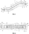
- Figure 1 is shown schematically a people transport device 1 in the side view.
- Figure 2 shows the passenger transport device 1 in a schematic representation according to Figure 1 in top view. Below are the two Figures 1 and 2 described together.
- the passenger transport device 1 can be both an escalator and a moving walkway. It connects a first floor EA with a second floor EB.
- the passenger transport device 1 has a supporting structure 5 or framework 5 with two deflection areas 7, 8, between which a step belt 4 or pallet belt 4, which is only indicated, is guided around the circumference.
- a handrail 3 is arranged on a balustrade 2. At its lower end, the balustrade 2 is connected to the supporting structure 5 by means of a balustrade base 9.
- the passenger transport device 1 or its supporting structure 5 has a first end 10 and a second end 11, which are supported by means of a support 6 in on-site support points 13, 14 of the first floor EA and the second floor EB.
- the support 6 has a pivot bearing 20 arranged at the first end 10 and a floating bearing 30 arranged at the second end 11.
- the pivot bearing point 20 has a pivot axis 21 which is arranged vertically with respect to its installation position.
- the floating bearing point 30 can accommodate horizontal movements 12 occurring orthogonally to the pivot axis 21.
- a support beam 22 arranged on the structure 5 is provided with a support beam 22 in the central longitudinal axis Y (see FIG Figure 2 ) the passenger transport device 1 arranged bore 23 is provided.
- the pivot bearing point 20 further comprises support packets 26, 27 arranged between the on-site support point 13 and the support beam 22, which in the present exemplary embodiment each comprise a support plate 26 and a damping element 27.
- the damping element 27 can, for example, be a plastic insert, a vibration-proof metal package and the like be.
- At least one leveling device 28, which, as shown in the present exemplary embodiment, can be an adjusting screw 28, is arranged between the support plate 26 and the support beam 22.
- the pivot bearing point 20 is spanned by a floor cover 29, which is indicated by way of illustration.
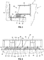
- FIG. 13 shows a front view of FIG Figure 5 illustrated floating bearing point 30 in its neutral or aligned operating position X N within the on-site bearing point 14.
- the floating bearing point 30 is arranged at the second end 11 of the passenger transport device 1. It is noticeable here that the floating bearing point 30 has an extraordinarily rigid box girder 31 which is firmly connected to the supporting structure 5 at the second end 11 of the passenger transport device 1.
- the floating bearing point 30 also has a support beam 32, which is firmly connected to the on-site bearing point 14 and forms the basis for two plain bearings 33.
- the two slide bearings 33 each have an upper slide 34 and a lower slide 35, the lower slide 35 including a slide plate 35.1 and a damping element 35.2.
- the damping element 35.2 can, for example, be a plastic insert, a vibrating metal package and the like.
- the upper slide 34 rests with its upper slide surface 34.1 on the lower slide surface 35.3 of the lower slide 35.
- the sliding surfaces 34.1, 35.3 can have suitable surface structures that result in a desired coefficient of sliding friction for the sliding bearing.
- leveling devices 36 are also provided between the upper slide 34 and the rigid box girder 31.
- Rolling bodies 37 are loosely arranged on the support beam 32 on both sides of the slide bearings 33.
- the rolling elements 37 of the illustrated embodiment are designed in the shape of a hollow cylinder. Their central longitudinal axes extend as if from the Figure 5 can be seen, parallel to the central longitudinal axis Y (see Figure 2 ) of the passenger transport device 1 and thus also parallel to the side edges 38 of the at least one slide bearing 33 extending in the longitudinal extension of the escalator 1 or the moving walk 1.
- the Figure 7 shows a larger view of the in Figure 6 designated details C.
- the diameter of the rolling element 37 is, as from the Figure 7 can be seen, somewhat greater than the thickness of the lower slide 35. This difference, referred to as elevation Z, enables the upper slide 34.1 to be at least partially lifted or lifted off the lower slide 35.3 when the upper slide 34 hits the rolling element 37.
- the elevation Z should not be too great and can be 0.1mm to 3.0mm, preferably 0.4mm to 2mm, particularly preferably 0.5mm to 1mm. From this it is also understandable why the box girder 31 must be designed to be particularly rigid.
- an run-up ramp 39 is formed on each side edge 38 of the upper slide 34 that is directed against a rolling element 37 and parallel to the rolling element 37.
- the ramp 39 should not be too steep and should have a ramp angle ⁇ between 5 ° and 30 °.
- the rolling element 37 can be connected to the support carrier by means of a mechanically releasable adhesive 40, a temperature-stable lubricating grease, an assembly grease or an adhesive grease. This prevents the rolling element 37 from rolling around within the floating bearing point 30 even with the slightest vibration.
- Air-hardening silicone rubber compound for example, can be used as the adhesive 40.
- the upper slide 34 reaches the rolling element 37 as a result of horizontal movements that occur, it is broken away from the support carrier 32 and can then roll unhindered.
- at least one end stop 41 can be provided on the bearing support 32 for each rolling element 37.
- the function of the floating bearing point 30 is also from the Figure 8 evident. This shows the in the Figure 6 illustrated floating bearing point 30 in a deflected position X R caused by horizontal movements 12 that have occurred. The course of the horizontal movements 12 of the upper slide 34 relative to the lower slide 35 from the neutral operating position X N into the deflected positions X R , X L is described below.
- the direction of movement of the horizontal movement 12 of the box girder 31 relative to the support girder 32 can change in the opposite direction before the rolling elements 37 reach the associated end stops 41.
- rolling friction and rolling friction first prevail in the floating bearing point 30 until the upper slide 34 leaves the rolling element 37 and slides over the lower slide 35. The course of movement described above is then repeated towards the other side.
- the in Figure 2 illustrated passenger transport device 1 checked, possibly disassembled and serviced.
- the floating bearing point 30 can also be checked and the second end 11 of the passenger transport device 1, if necessary, brought from a deflected position X R or X L into the neutral operating position X N and aligned.
Description
Die Erfindung betrifft ein Auflager zur bauseitigen Lagerung der beiden Enden einer Personentransporteinrichtung, insbesondere einer Fahrtreppe oder eines Fahrsteiges.The invention relates to a support for on-site storage of the two ends of a passenger transport device, in particular an escalator or a moving walkway.
Üblicherweise werden Fahrtreppen beziehungsweise Fahrsteige an ihren beiden Enden auf elastischen Auflagerelementen gelagert, die je aus einer Stahlplatte und einer elastischen Zwischenlage bestehen. Nachteilig bei diesem Auflager ist, dass bei übermäßigen Bewegungen Querkräfte entstehen können, bei deren Einwirkung ein Tragwerk beziehungsweise ein Fachwerk der Personentransporteinrichtung deformiert werden kann.Usually, escalators or moving walks are supported at their two ends on elastic support elements, each of which consists of a steel plate and an elastic intermediate layer. The disadvantage of this support is that excessive movements can result in transverse forces which, when they act, can deform a supporting structure or a framework of the passenger transport device.
Diese übermäßigen Bewegungen entstehen beispielsweise durch auf ein Bauwerk einwirkende Schwingungen und Stöße von Erdbeben. Die Querkräfte entstehen infolge der Massenträgheit der Personentransporteinrichtung selbst und durch die Bewegungen von Etagen des Bauwerks, die sich in horizontaler Richtung relativ zueinander bewegen. Eine Personentransporteinrichtung die zwei Etagen verbindet, kann durch die horizontalen Bewegungen der Etagen aus den Auflagern springen oder es können Beschädigungen am Bauwerk und/oder an der Fahrtreppe beziehungsweise am Fahrsteig auftreten.These excessive movements are caused, for example, by vibrations and shocks from earthquakes acting on a building. The transverse forces arise as a result of the inertia of the passenger transport device itself and as a result of the movements of the floors of the building, which move in a horizontal direction relative to one another. A passenger transport device that connects two floors can jump out of the supports due to the horizontal movements of the floors or damage to the building and / or to the escalator or moving walk can occur.
Um solche Beschädigungen zu verhindern, schlägt die
Die in der
Die Aufgabe der vorliegenden Erfindung besteht darin, ein Auflager zu schaffen, das auch schnelle horizontale Bewegungen im Bereich des Auflagers zu entkoppeln vermag. Diese Aufgabe wird durch ein Auflager zur bauseitigen Lagerung der beiden Enden einer Personentransporteinrichtung mit den Merkmalen des Anspruchs 1 gelöst. Dieses Auflager weist eine am ersten Ende der Personentransporteinrichtung vorgesehene Schwenklagerstelle auf, deren Schwenkachse bezüglich ihrer Einbaulage vertikal angeordnet ist. Des Weiteren weist das Auflager eine am zweiten Ende der Personentransporteinrichtung vorgesehene Loslagerstelle zur Aufnahme orthogonal zur Schwenkachse auftretender, horizontaler Bewegungen auf. Um die horizontalen Bewegungen unabhängig von deren Geschwindigkeit aufnehmen zu können, weist die Loslagerstelle mindestens einen Wälzkörper auf. Durch diesen mindestens einen Wälzkörper kann eine in der Loslagerstelle durch horizontal auftretende Bewegungen verursachte Gleitreibung in Wälzreibung oder Rollreibung überführt werden.The object of the present invention is to create a support which is also able to decouple rapid horizontal movements in the area of the support. This object is achieved by a support for on-site storage of the two ends of a passenger transport device with the features of
Bei sehr langsamen und daher niederfrequenten Schwingungen folgt das zweite Ende der Personentransporteinrichtung im Wesentlichen den Bewegungen der angrenzenden Etage nach. Ab einer Grenzgeschwindigkeit, die im Wesentlichen vom Reibungskoeffizienten und der Auflagerlast der Loslagerstelle und der Massenträgheit der Personentransporteinrichtung abhängig ist, werden die horizontalen Bewegungen teilweise in der Loslagerstelle aufgenommen, indem sich das zweite Ende der Personentransporteinrichtung relativ zur angrenzenden Etage verschiebt. Wenn diese Schwingungen kleine Amplituden aufweisen, wird die Struktur der Personentransporteinrichtung, insbesondere deren Tragwerk nur im elastischen Bereich beansprucht, so dass an diesem keine plastischen Deformationen auftreten. Wenn diese Schwingungen aber große Amplituden aufweisen, wird nach kurzer Gleitstrecke durch den mindestens einen Wälzkörper der Reibungswiderstand in der Loslagerstelle drastisch reduziert, so dass die infolge des Reibungswiderstandes auf das zweite Ende wirkende Querkraft nahezu eliminiert und das Tragwerk entlastet wird.In the case of very slow and therefore low-frequency vibrations, the second end of the passenger transport device essentially follows the movements of the adjacent floor. Above a limit speed, which is essentially dependent on the coefficient of friction and the bearing load of the floating bearing point and the inertia of the passenger transport device, the horizontal movements are partially absorbed in the floating bearing point as the second end of the passenger transport device moves relative to the adjacent floor. If these vibrations have small amplitudes, the structure of the passenger transport device, in particular its supporting structure, is only stressed in the elastic area, so that no plastic deformations occur in this area. However, if these vibrations have large amplitudes, the frictional resistance in the floating bearing point is drastically reduced after a short sliding distance by the at least one rolling element, so that the frictional resistance increases the lateral force acting on the second end is almost eliminated and the load-bearing structure is relieved.
Die vorliegende Erfindung verhindert ferner, dass das zweite Ende in neutraler Betriebslage seitlich pendelt, da die Haftreibung der Loslagerstelle nicht durch das Betreten der Benutzer überwunden werden kann. Zudem ist der mindestens eine Wälzkörper in der neutralen Betriebslage der Personentransporteinrichtung lastfrei und wird daher im Laufe der Zeit nicht durch eine hohe statische Last plastisch deformiert.The present invention also prevents the second end from swinging laterally in the neutral operating position, since the static friction of the floating bearing point cannot be overcome by the user stepping on it. In addition, the at least one rolling element is load-free in the neutral operating position of the passenger transport device and is therefore not plastically deformed over time by a high static load.
Damit möglichst definierte Gleitreibungseigenschaften vorhanden sind, weist die Loslagerstelle mindestens ein Gleitlager auf. Zu den beiden, parallel zur Längserstreckung der Fahrtreppe oder des Fahrsteiges sich erstreckenden Seitenkanten des mindestens einen Gleitlagers sind Wälzkörper angeordnet. Dadurch kann die bei horizontalen Bewegungen auftretende Gleitreibung in beiden Bewegungsrichtungen in Wälzreibung oder Rollreibung überführt werden.The floating bearing point has at least one plain bearing so that the dynamic friction properties are as defined as possible. Rolling bodies are arranged on the two side edges of the at least one slide bearing that extend parallel to the longitudinal extension of the escalator or the moving walk. As a result, the sliding friction that occurs during horizontal movements can be converted into rolling friction or rolling friction in both directions of movement.
Das mindestens eine Gleitlager weist ein oberes Gleitstück und ein unteres Gleitstück auf. Das obere und das untere Gleitstück weisen je eine Gleitfläche auf, die einander zugewandt sind. Die Gleitflächen können geeignete Oberflächenstrukturen aufweisen, die einen gewünschten Gleitreibungskoeffizienten des Gleitlagers ergeben. Durch die Loslagerstelle können auch Längsdehnungen der Personentransporteinrichtung aufgenommen werden. Die Loslagerstelle kann bei ausreichend breit ausgelegtem Gleitlager aber auch Verschiebungen der beiden Etagen relativ zueinander aufnehmen, die in Richtung der Längserstreckung der Personentransporteinrichtung erfolgen.The at least one slide bearing has an upper slide and a lower slide. The upper and the lower slider each have a sliding surface facing each other. The sliding surfaces can have suitable surface structures which result in a desired coefficient of sliding friction for the sliding bearing. Longitudinal expansions of the passenger transport device can also be absorbed by the floating bearing point. If the plain bearing is designed to be sufficiently wide, the floating bearing point can also accommodate displacements of the two floors relative to one another, which take place in the direction of the longitudinal extension of the passenger transport device.
Um die Überführung der Gleitreibung in Wälzreibung oder Rollreibung zu erleichtern, ist an jeder gegen einen Wälzkörper gerichteten Seitenkante des oberen Gleitstücks eine Auflauframpe ausgebildet. Diese Auflauframpe dient dem Auflaufen des oberen Gleitstücks auf den Wälzkörper. Beim Auflaufen kann das obere Gleitstück vom unteren Gleitstück zumindest teilweise abheben und rollt dann auf dem mindestens einen Wälzkörper weiter.In order to facilitate the conversion of sliding friction into rolling friction or rolling friction, an overrun ramp is formed on each side edge of the upper slide that is directed against a rolling element. This run-up ramp is used to run the upper slide on the rolling element. When running up, the upper slide can at least partially lift off the lower slide and then continue to roll on the at least one rolling element.
Um dem Wälzkörper eine geeignete Laufbahn bereitzustellen, kann die Loslagerstelle einen bauseitig verankerbaren Auflagerträger aufweisen. Das Vorhandensein eines Auflagerträgers ermöglicht, das untere Gleitstück mit dem Auflagerträger zu verbinden. Das obere Gleitstück ist mit dem zweiten Ende der Personentransporteinrichtung auf geeignete Art verbunden. Ferner kann zwischen dem oberen Gleitstück und dem zweiten Ende eine Nivelliereinrichtung angeordnet sein. Diese Nivelliereinrichtung dient der verzugsfreien und bündigen Ausrichtung des zweiten Endes zum Etagenboden. Als Nivelliereinrichtung können beispielsweise Stellschrauben, Distanzbleche, Distanzscheiben, Distanzhülsen und dergleichen mehr verwendet werden.In order to provide the rolling element with a suitable raceway, the floating bearing point can have a bearing support that can be anchored on site. The presence of a support beam enables the lower slide to be connected to the support beam. The upper slide is connected to the second end of the passenger conveyor in a suitable manner. Furthermore, between the upper slide and the second end a leveling device can be arranged. This leveling device is used to align the second end flush with the floor without distortion. Adjusting screws, spacer plates, spacer disks, spacer sleeves and the like can be used as leveling devices.
Der mindestens eine Wälzkörper kann seitlich der Auflauframpe angeordnet, mittels eines mechanisch lösbaren Klebstoffs mit dem Auflagerträger verbunden sein. Dadurch verharrt der Wälzkörper in seiner Position innerhalb der Loslagerstelle, bis durch eine horizontale Bewegung das obere Gleitstück den Wälzkörper beim Auflaufen losbricht. Selbstverständlich kann an Stelle eines Klebstoffs auch temperaturstabiles Schmierfett, Montagefett oder Haftfett verwendet werden.The at least one rolling element can be arranged to the side of the ramp and connected to the support beam by means of a mechanically releasable adhesive. As a result, the rolling element remains in its position within the floating bearing point until the upper sliding piece breaks loose when the rolling element runs up due to a horizontal movement. Of course, temperature-stable lubricating grease, assembly grease or adhesive grease can also be used instead of an adhesive.
Der Auflagerträger kann auch mindestens einen Endanschlag zur Begrenzung der Rollstrecke des mindestens einen Wälzkörpers aufweisen. Dies hat den Vorteil, dass sich der mindestens eine Wälzkörper immer in einem begrenzten Bereich befindet und zur Verfügung steht.The support beam can also have at least one end stop to limit the rolling path of the at least one rolling element. This has the advantage that the at least one rolling element is always located and available in a limited area.
Damit sich durch den Betrieb der Personentransporteinrichtung auftretende Vibrationen nicht auf das Gebäude übertragen können, weist das untere Gleitstück vorzugsweise ein Dämpfungselement beziehungsweise eine Schallisolation auf.So that vibrations occurring during the operation of the passenger transport device cannot be transmitted to the building, the lower slide preferably has a damping element or sound insulation.
Wie bereits weiter oben erläutert, kann die Personentransporteinrichtung als Fahrtreppe oder als Fahrsteig ausgebildet sein. Personentransporteinrichtungen können nicht nur ab Werk mit dem erfindungsgemäßen Auflager versehen sein. Auch bestehende Personentransporteinrichtungen können mit dem erfindungsgemäßen Auflager nachgerüstet werden. Eine solche Modernisierung umfasst die Schritte:
- dass die beiden Enden der bestehenden Personentransporteinrichtung miteinander oder nacheinander angehoben werden,
- dass die beiden Enden der bestehenden Personentransporteinrichtung sowie deren bauseitigen Auflagerstellen zur Aufnahme eines erfindungsgemäßen Auflagers vorbereitet werden,
- dass zwischen dem ersten Ende der Personentransporteinrichtung und dessen bauseitiger Auflagerstelle die Schwenklagerstelle des Auflagers angeordnet wird und
- dass zwischen dem zweiten Ende der Personentransporteinrichtung und dessen bauseitiger Auflagerstelle die Loslagerstelle des Auflagers angeordnet wird.
- that the two ends of the existing passenger transport system are lifted together or one after the other,
- that the two ends of the existing passenger transport device as well as their on-site support points are prepared to accommodate a support according to the invention,
- that between the first end of the passenger transport device and its on-site support point, the pivot bearing point of the support is arranged and
- that between the second end of the passenger transport device and its on-site support point, the loose bearing point of the support is arranged.
Das Auflager zur bauseitigen Lagerung der beiden Enden einer Personentransporteinrichtung wird im Folgenden anhand von Beispielen und mit Bezugnahme auf die Zeichnungen näher erläutert. Darin zeigen:
- Figur 1:
- in schematischer Darstellung eine Personentransporteinrichtung in der Seitenansicht;
- Figur 2:
- in schematischer Darstellung die Personentransporteinrichtung gemäß
Figur 1 - Figur 3:
- eine größere Ansicht des in
der Figur 1 bezeichneten Details B, darstellend eine an einem ersten Ende der Personentransporteinrichtung angeordnete Schwenklagerstelle des Auflagers; - Figur 4:
- einen Schnitt durch die in
der Figur 3 dargestellte Schwenklagerstelle entlang der Linie D-D; - Figur 5:
- einen größer dargestellten Schnitt des in
der Figur 1 bezeichneten Details A, darstellend eine an einem zweiten Ende der Personentransporteinrichtung angeordnete Loslagerstelle des Auflagers; - Figur 6:
- eine Frontansicht der in
der Figur 5 dargestellten Loslagerstelle in ihrer neutralen beziehungsweise ausgerichteten Betriebslage; - Figur 7:
- eine größere Ansicht des in
der Figur 6 bezeichneten Details C und - Figur 8:
- die in
der Figur 6 dargestellte Loslagerstelle in ihrer, durch aufgetretene horizontale Bewegungen verursachten ausgelenkten Lage.
- Figure 1:
- a schematic representation of a passenger transport device in a side view;
- Figure 2:
- in a schematic representation of the passenger transport device according to
Figure 1 in plan view; - Figure 3:
- a larger view of the in the
Figure 1 designated details B, showing a pivot bearing point of the support arranged at a first end of the passenger transport device; - Figure 4:
- a section through those in the
Figure 3 pivot bearing shown along the line DD; - Figure 5:
- a larger section of the in the
Figure 1 designated details A, representing a movable bearing point of the support arranged at a second end of the passenger transport device; - Figure 6:
- a front view of the
Figure 5 illustrated floating bearing in its neutral or aligned operating position; - Figure 7:
- a larger view of the in the
Figure 6 designated details C and - Figure 8:
- those in the
Figure 6 The floating bearing shown in its deflected position caused by horizontal movements that have occurred.
In der
Die Personentransporteinrichtung 1 kann sowohl eine Fahrtreppe als auch ein Fahrsteig sein. Sie verbindet eine erste Etage EA mit einer zweiten Etage EB. Die Personentransporteinrichtung 1 weist ein Tragwerk 5 beziehungsweise Fachwerk 5 mit zwei Umlenkbereichen 7, 8 auf, zwischen denen ein nur andeutungsweise dargestelltes Stufenband 4 oder Palettenband 4 umlaufend geführt ist. Ein Handlauf 3 ist an einer Balustrade 2 angeordnet. Die Balustrade 2 ist an ihrem unteren Ende mittels eines Balustradensockels 9 mit dem Tragwerk 5 verbunden.The
Die Personentransporteinrichtung 1 beziehungsweise deren Tragwerk 5 weist ein erstes Ende 10 und ein zweites Ende 11 auf, die mittels eines Auflagers 6 in bauseitigen Auflagestellen 13, 14 der ersten Etage EA und der zweiten Etage EB gelagert sind. Das Auflager 6 weist eine am ersten Ende 10 angeordnete Schwenklagerstelle 20 und eine am zweiten Ende 11 angeordnete Loslagerstelle 30 auf. Die Schwenklagerstelle 20 weist eine Schwenkachse 21 auf, die bezüglich ihrer Einbaulage vertikal angeordnet ist. Die Loslagerstelle 30 kann orthogonal zur Schwenkachse 21 auftretende, horizontale Bewegungen 12 aufnehmen.The
In den
Ein am Tragwerk 5 angeordneter Auflagerträger 22 ist mit einer in der Mittellängsachse Y (siehe
Da auch das zweite Ende 11 der Personentransporteinrichtung 1 zur bauseitigen Auflagerstelle 14 ausgerichtet werden muss, sind zwischen dem oberen Gleitstück 34 und dem steifen Kastenträger 31 ebenfalls Nivelliereinrichtungen 36 vorgesehen.Since the
Zu beiden Seiten der Gleitlager 33 sind Wälzkörper 37 lose auf dem Auflagerträger 32 angeordnet. Die Wälzkörper 37 des dargestellten Ausführungsbeispiels sind hohlzylinderförmig ausgebildet. Deren Mittellängsachsen erstrecken sich wie aus der
Die
Damit der Wälzkörper 37 bis zum Auftreten von horizontalen Bewegungen eine definierte Position innerhalb der Loslagerstelle 30 behält, kann dieser mittels eines mechanisch lösbaren Klebstoffs 40, eines temperaturstabilen Schmierfetts, eines Montagefetts oder eines Haftfetts mit dem Auflageträger verbunden sein. Dadurch wird verhindert, dass der Wälzkörper 37 nicht schon bei geringsten Vibrationen innerhalb der Loslagerstelle 30 herumrollt. Als Klebstoff 40 kann beispielsweise lufthärtende Silikonkautschukmasse verwendet werden. Sobald das obere Gleitstück 34 infolge auftretender horizontaler Bewegungen den Wälzkörper 37 erreicht, wird dieser vom Auflageträger 32 losgebrochen und kann dann ungehindert rollen. Um dessen Rollstrecke zu begrenzen, kann am Auflagerträger 32 für jeden Wälzkörper 37 mindestens ein Endanschlag 41 vorgesehen sein.So that the rolling
Die Funktion der Loslagerstelle 30 ist auch aus der
Wenn schnelle horizontale Bewegungen 12 auftreten, durch welche die Haftreibung zwischen den Gleitflächen 34.1, 35.3 der Gleitlager 33 überwunden wird, erfolgt eine Relativverschiebung zwischen dem oberen Gleitstück 34 und dem unteren Gleitstück 35. Dabei tritt Gleitreibung auf, bis das obere Gleitstück 34 auf einen Wälzkörper 37aufläuft. Die auflaufende Seite des oberen Gleitstücks 34 wird angehoben und dabei innerhalb der Loslagerstelle 30 die Gleitreibung in Wälzreibung (Gleitreibung und Rollreibung) überführt. Je nach Rollstrecke des oberen Gleitstücks 34 auf dem Wälzkörper 37, kann auch eine vollständige Trennung der beiden Gleitflächen 34.1, 35.3 des Gleitlagers 33 erfolgen, wodurch eine nahezu reine Rollreibung in der Loslagerstelle 30 vorherrscht. Da sich Naturereignisse wie Erdbeben üblicherweise nicht durch einzelne Stöße, sondern durch Schwingungen mit stark abklingenden Amplituden ausweisen, kann die Bewegungsrichtung der horizontalen Bewegung 12 des Kastenträgers 31 relativ zum Auflagerträger 32 in die Gegenrichtung ändern, bevor die Wälzkörper 37 die zugeordneten Endanschläge 41 erreichen. Bei der anschließenden Bewegung 12 in der Gegenrichtung herrscht zuerst Rollreibung und Wälzreibung in der Loslagerstelle 30 vor, bis das obere Gleitstück 34 den Wälzkörper 37 verlässt und über das untere Gleitstück 35 gleitet. Zur andern Seite hin wiederholt sich dann der vorangehend beschriebene Bewegungsverlauf.When rapid
Nach einem Ereignis beziehungsweise Erdbeben muss die in
Obwohl die Erfindung durch die Darstellung spezifischer Ausführungsbeispiele beschrieben worden ist, ist es offensichtlich, dass zahlreiche weitere Ausführungsvarianten in Kenntnis der vorliegenden Erfindung geschaffen werden können, beispielsweise indem anstelle der Wälzkörper 37 am Auflagerträger 32 drehgelagerte Rollen, Kugeln, Kugelführungen oder dergleichen mehr angeordnet sind. Ferner können die Auflauframpen 39 auch am unteren Gleitstück 35 und die drehgelagerten Rollen am Kastenträger 31 angeordnet sein. Selbstverständlich sind anstelle von zylinderrohrförmigen Wälzkörpern 37 auch vollzylindrische Wälzkörper ohne Bohrung einsetzbar. Der Auflagerträger 32 kann ferner leicht gegen die Gleitlager 33 geneigte Rollbahnen für die Wälzkörper 37 aufweisen, so dass sich das zweite Ende 11 der Personentransporteinrichtung 1 nach einem Ereignis infolge der Schwerkraft zumindest teilweisewieder selbst in die neutrale Betriebslage XN ausrichtet.Although the invention has been described by showing specific exemplary embodiments, it is obvious that numerous other design variants can be created with knowledge of the present invention, for example by arranging rotatably mounted rollers, balls, ball guides or the like instead of the rolling
Claims (8)
- Support (6) for on-site mounting of the two ends (10, 11) of a passenger transport device (1), having a pivot bearing point (20) provided at the first end (10) of the passenger transport device (1), the pivot axis (21) of which is arranged vertically with respect to its installation position, and a floating bearing point (30) provided at the second end (11) of the passenger transport device (1) for accommodating horizontal movements (12) occurring orthogonally to the pivot axis (21), the floating bearing point (30) having at least one rolling element (37), by means of which rolling element (37) a sliding friction caused in the floating bearing point (30) by horizontally occurring movements (12) can be converted into rolling friction, the floating bearing point (30) having at least one sliding bearing (33) and rolling elements (37) being arranged on the two side edges (38) of the at least one sliding bearing (33) which extend parallel to the longitudinal extension (Y) of the passenger transport device (1), and the at least one slide bearing (33) having an upper slide (34) and a lower slide (35), characterized in that a run-on ramp (39) is formed on each side edge (38) of the upper slide (34) directed towards a rolling element (37), which run-on ramp (39) is used to run the upper slide (34) on the rolling element (37), so that after a lateral, horizontal movement (12) of the second end (11), the upper slide (34) is at least partially lifted from the lower slide (35).
- Support (6) according to claim 1, wherein the floating bearing point (30) has a support beam (32) which can be anchored on-site.
- Support (6) according to claim 2, wherein the upper slide (34) is connected to the second end (11) and the lower slide (35) is connected to the support beam (32).
- Support (6) according to either claim 2 or claim 3, wherein the at least one rolling element (37) is arranged on the side of the run-on ramp (39), connected to the support beam (32) by means of a mechanically releasable adhesive (40), a temperature-stable lubricating grease, an assembly grease or an adhesive grease.
- Support (6) according to any of claims 2 to 4, the support beam (32) having at least one end stop (41) for limiting the rolling path of the at least one rolling element (37).
- Support (6) according to any of claims 2 to 5, the lower slide (35) having a damping element (35.2).
- Passenger transport device (1) which is configured as an escalator or a moving walkway, having a support (6) according to any of claims 1 to 6.
- Method for modernizing an existing passenger transport device (1), comprising the steps• whereby the two ends (10, 11) of the existing passenger transport device (1) are raised,• whereby the two ends (10, 11) of the existing passenger transport device (1) and the on-site support points (13, 14) thereof are prepared for receiving a support (6) according to any of claims 1 to 6,• whereby the pivot bearing point (20) of the support (6) is arranged between the first end (10) of the passenger transport device (1) and the on-site support point (13) thereof and whereby the floating bearing point (30) of the support (6) is arranged between the second end (11) of the passenger transport device (1) and the on-site support point (14) thereof.
Priority Applications (1)
| Application Number | Priority Date | Filing Date | Title |
|---|---|---|---|
| EP14800015.1A EP3077321B1 (en) | 2013-12-06 | 2014-11-14 | Support for supporting a passenger transportation device |
Applications Claiming Priority (3)
| Application Number | Priority Date | Filing Date | Title |
|---|---|---|---|
| EP13196071 | 2013-12-06 | ||
| PCT/EP2014/074637 WO2015082195A1 (en) | 2013-12-06 | 2014-11-14 | Support for supporting a person conveying device on a structure |
| EP14800015.1A EP3077321B1 (en) | 2013-12-06 | 2014-11-14 | Support for supporting a passenger transportation device |
Publications (2)
| Publication Number | Publication Date |
|---|---|
| EP3077321A1 EP3077321A1 (en) | 2016-10-12 |
| EP3077321B1 true EP3077321B1 (en) | 2021-09-22 |
Family
ID=49725053
Family Applications (1)
| Application Number | Title | Priority Date | Filing Date |
|---|---|---|---|
| EP14800015.1A Active EP3077321B1 (en) | 2013-12-06 | 2014-11-14 | Support for supporting a passenger transportation device |
Country Status (8)
| Country | Link |
|---|---|
| US (1) | US9834416B2 (en) |
| EP (1) | EP3077321B1 (en) |
| JP (1) | JP2016539061A (en) |
| KR (1) | KR102263794B1 (en) |
| CN (1) | CN105793185B (en) |
| ES (1) | ES2894733T3 (en) |
| MX (1) | MX2016007185A (en) |
| WO (1) | WO2015082195A1 (en) |
Families Citing this family (7)
| Publication number | Priority date | Publication date | Assignee | Title |
|---|---|---|---|---|
| DE102015214077A1 (en) * | 2015-07-24 | 2017-01-26 | Thyssenkrupp Ag | Transport device, in particular escalator or moving walk |
| PL3390264T3 (en) * | 2015-12-17 | 2020-06-29 | Inventio Ag | Floor covering of a passenger conveying device |
| CN108473284B (en) * | 2016-01-21 | 2019-07-12 | 三菱电机株式会社 | Passenger conveyors |
| JP6184572B1 (en) * | 2016-09-21 | 2017-08-23 | 東芝エレベータ株式会社 | Passenger conveyor and its mounting method |
| US10513420B2 (en) * | 2016-10-18 | 2019-12-24 | Inventio Ag | Floor cover for a passenger-conveying device |
| JP6382400B1 (en) * | 2017-07-03 | 2018-08-29 | 東芝エレベータ株式会社 | Passenger conveyor and its mounting method |
| JP6743984B2 (en) * | 2017-11-22 | 2020-08-19 | 三菱電機株式会社 | Passenger conveyor |
Family Cites Families (16)
| Publication number | Priority date | Publication date | Assignee | Title |
|---|---|---|---|---|
| JPS5936922B2 (en) | 1976-08-26 | 1984-09-06 | 三井東圧化学株式会社 | Method for producing rubber-modified impact-resistant polymer |
| JPS5742941Y2 (en) * | 1976-10-06 | 1982-09-21 | ||
| JPS5875273A (en) | 1981-10-29 | 1983-05-06 | Fujitsu Ltd | Restoration system for stored information |
| JPS5875273U (en) * | 1981-11-18 | 1983-05-21 | 株式会社日立製作所 | Electric road support structure |
| JPH10316351A (en) * | 1997-05-19 | 1998-12-02 | Taisei Corp | Escalator for base isolation building |
| JP2886527B1 (en) | 1998-04-17 | 1999-04-26 | 鹿島建設株式会社 | Seismic isolation escalator |
| EP0963941B1 (en) | 1998-06-11 | 2003-08-20 | Inventio Ag | Support for escalator or moving walkway |
| CN1187256C (en) * | 1998-06-11 | 2005-02-02 | 因温特奥股份公司 | Bed for escalator or moving walkway |
| JP2000095471A (en) * | 1998-09-18 | 2000-04-04 | Takenaka Komuten Co Ltd | Base-isolated escalator |
| JP2000120301A (en) * | 1998-10-14 | 2000-04-25 | Toyo Tire & Rubber Co Ltd | Base isolation device for light-weight structure |
| JP3456932B2 (en) * | 1999-12-16 | 2003-10-14 | 株式会社日立製作所 | Escalator installation method |
| US6637580B1 (en) * | 2002-12-05 | 2003-10-28 | Terryle L. Sneed | Telescoping escalator seismic restraint |
| JP2011051775A (en) * | 2009-09-04 | 2011-03-17 | Toshiba Elevator Co Ltd | Driving device of passenger conveyor |
| JP2012025555A (en) * | 2010-07-26 | 2012-02-09 | Toshiba Elevator Co Ltd | Machine plate of passenger conveyor |
| JP2012062131A (en) * | 2010-09-14 | 2012-03-29 | Hitachi Ltd | Passenger conveyor |
| BR112014029227A2 (en) * | 2012-06-21 | 2017-06-27 | Mitsubishi Electric Corp | treadmill |
-
2014
- 2014-11-14 ES ES14800015T patent/ES2894733T3/en active Active
- 2014-11-14 KR KR1020167014865A patent/KR102263794B1/en active IP Right Grant
- 2014-11-14 CN CN201480065327.5A patent/CN105793185B/en active Active
- 2014-11-14 MX MX2016007185A patent/MX2016007185A/en active IP Right Grant
- 2014-11-14 WO PCT/EP2014/074637 patent/WO2015082195A1/en active Application Filing
- 2014-11-14 EP EP14800015.1A patent/EP3077321B1/en active Active
- 2014-11-14 US US15/101,979 patent/US9834416B2/en active Active
- 2014-11-14 JP JP2016536597A patent/JP2016539061A/en active Pending
Also Published As
| Publication number | Publication date |
|---|---|
| WO2015082195A1 (en) | 2015-06-11 |
| US9834416B2 (en) | 2017-12-05 |
| KR102263794B1 (en) | 2021-06-11 |
| ES2894733T3 (en) | 2022-02-15 |
| US20160304322A1 (en) | 2016-10-20 |
| CN105793185A (en) | 2016-07-20 |
| KR20160096604A (en) | 2016-08-16 |
| JP2016539061A (en) | 2016-12-15 |
| EP3077321A1 (en) | 2016-10-12 |
| MX2016007185A (en) | 2016-07-21 |
| CN105793185B (en) | 2019-05-10 |
Similar Documents
| Publication | Publication Date | Title |
|---|---|---|
| EP3077321B1 (en) | Support for supporting a passenger transportation device | |
| DE3146330C2 (en) | Rolling bearings for guiding a linear movement | |
| EP2079342B1 (en) | Pull-out guide for drawers | |
| EP2900586B1 (en) | Guide element for a guide rail of an escalator or moving pathway | |
| DE112012006051B4 (en) | elevator | |
| EP3321459B1 (en) | Carriages and fitting for a sliding door | |
| WO1994026146A1 (en) | Slide mechanism for a drawer | |
| DE102004044208B4 (en) | Arrangement for stabilizing supporting structures | |
| EP3325397B1 (en) | Transporting apparatus, in particular escalator or moving walkway | |
| WO2018234273A1 (en) | Supporting device for a rotary platform in an elevator system | |
| EP2990529B1 (en) | Intermediate layer | |
| DE102011050977A1 (en) | Bridging device in center beam design for a building joint | |
| DE19753169C2 (en) | Device for hanging a rail, in particular a hollow profile-shaped rail of a suspension crane that is open at the bottom | |
| WO2014095331A1 (en) | Escalator or moving walkway with a transparent balustrade | |
| DE102013100357A1 (en) | Device for force-transmitting connection of a first supporting part of the building with a second supported part of the building | |
| EP3101271B1 (en) | System and method for transporting and lifting a rotor blade of a wind turbine | |
| EP2754766B1 (en) | Device for connecting a first supporting building part with a second supported building part in a manner that transfers force | |
| DE2749928C2 (en) | ||
| DE102011120071A1 (en) | Movable bearing device for piping roof in construction building during scaffolding work, has lift protecting unit protecting device against lifting from rail profile and designed so that lift protection is ensured during shifting process | |
| DE102022207585A1 (en) | Structural vibration damper | |
| AT504234B1 (en) | SLIDING DOOR OR SLIDING DOOR | |
| DE102021102703A1 (en) | structure | |
| DE1930612U (en) | ELASTIC MOUNTING ELEMENT. | |
| DE102017208215A1 (en) | Building warehouse and building with such a building warehouse | |
| EP3562999B1 (en) | Device for moving a tongue rail of a gate |
Legal Events
| Date | Code | Title | Description |
|---|---|---|---|
| PUAI | Public reference made under article 153(3) epc to a published international application that has entered the european phase |
Free format text: ORIGINAL CODE: 0009012 |
|
| STAA | Information on the status of an ep patent application or granted ep patent |
Free format text: STATUS: REQUEST FOR EXAMINATION WAS MADE |
|
| 17P | Request for examination filed |
Effective date: 20160502 |
|
| AK | Designated contracting states |
Kind code of ref document: A1 Designated state(s): AL AT BE BG CH CY CZ DE DK EE ES FI FR GB GR HR HU IE IS IT LI LT LU LV MC MK MT NL NO PL PT RO RS SE SI SK SM TR |
|
| AX | Request for extension of the european patent |
Extension state: BA ME |
|
| DAX | Request for extension of the european patent (deleted) | ||
| STAA | Information on the status of an ep patent application or granted ep patent |
Free format text: STATUS: EXAMINATION IS IN PROGRESS |
|
| 17Q | First examination report despatched |
Effective date: 20210406 |
|
| GRAP | Despatch of communication of intention to grant a patent |
Free format text: ORIGINAL CODE: EPIDOSNIGR1 |
|
| STAA | Information on the status of an ep patent application or granted ep patent |
Free format text: STATUS: GRANT OF PATENT IS INTENDED |
|
| INTG | Intention to grant announced |
Effective date: 20210611 |
|
| GRAS | Grant fee paid |
Free format text: ORIGINAL CODE: EPIDOSNIGR3 |
|
| GRAA | (expected) grant |
Free format text: ORIGINAL CODE: 0009210 |
|
| STAA | Information on the status of an ep patent application or granted ep patent |
Free format text: STATUS: THE PATENT HAS BEEN GRANTED |
|
| AK | Designated contracting states |
Kind code of ref document: B1 Designated state(s): AL AT BE BG CH CY CZ DE DK EE ES FI FR GB GR HR HU IE IS IT LI LT LU LV MC MK MT NL NO PL PT RO RS SE SI SK SM TR |
|
| REG | Reference to a national code |
Ref country code: GB Ref legal event code: FG4D Free format text: NOT ENGLISH |
|
| REG | Reference to a national code |
Ref country code: IE Ref legal event code: FG4D Free format text: LANGUAGE OF EP DOCUMENT: GERMAN |
|
| REG | Reference to a national code |
Ref country code: DE Ref legal event code: R096 Ref document number: 502014015894 Country of ref document: DE |
|
| REG | Reference to a national code |
Ref country code: CH Ref legal event code: EP Ref country code: AT Ref legal event code: REF Ref document number: 1432190 Country of ref document: AT Kind code of ref document: T Effective date: 20211015 |
|
| REG | Reference to a national code |
Ref country code: LT Ref legal event code: MG9D |
|
| REG | Reference to a national code |
Ref country code: NL Ref legal event code: MP Effective date: 20210922 |
|
| PG25 | Lapsed in a contracting state [announced via postgrant information from national office to epo] |
Ref country code: LT Free format text: LAPSE BECAUSE OF FAILURE TO SUBMIT A TRANSLATION OF THE DESCRIPTION OR TO PAY THE FEE WITHIN THE PRESCRIBED TIME-LIMIT Effective date: 20210922 Ref country code: BG Free format text: LAPSE BECAUSE OF FAILURE TO SUBMIT A TRANSLATION OF THE DESCRIPTION OR TO PAY THE FEE WITHIN THE PRESCRIBED TIME-LIMIT Effective date: 20211222 Ref country code: FI Free format text: LAPSE BECAUSE OF FAILURE TO SUBMIT A TRANSLATION OF THE DESCRIPTION OR TO PAY THE FEE WITHIN THE PRESCRIBED TIME-LIMIT Effective date: 20210922 Ref country code: NO Free format text: LAPSE BECAUSE OF FAILURE TO SUBMIT A TRANSLATION OF THE DESCRIPTION OR TO PAY THE FEE WITHIN THE PRESCRIBED TIME-LIMIT Effective date: 20211222 Ref country code: HR Free format text: LAPSE BECAUSE OF FAILURE TO SUBMIT A TRANSLATION OF THE DESCRIPTION OR TO PAY THE FEE WITHIN THE PRESCRIBED TIME-LIMIT Effective date: 20210922 Ref country code: SE Free format text: LAPSE BECAUSE OF FAILURE TO SUBMIT A TRANSLATION OF THE DESCRIPTION OR TO PAY THE FEE WITHIN THE PRESCRIBED TIME-LIMIT Effective date: 20210922 Ref country code: RS Free format text: LAPSE BECAUSE OF FAILURE TO SUBMIT A TRANSLATION OF THE DESCRIPTION OR TO PAY THE FEE WITHIN THE PRESCRIBED TIME-LIMIT Effective date: 20210922 |
|
| REG | Reference to a national code |
Ref country code: ES Ref legal event code: FG2A Ref document number: 2894733 Country of ref document: ES Kind code of ref document: T3 Effective date: 20220215 |
|
| PG25 | Lapsed in a contracting state [announced via postgrant information from national office to epo] |
Ref country code: LV Free format text: LAPSE BECAUSE OF FAILURE TO SUBMIT A TRANSLATION OF THE DESCRIPTION OR TO PAY THE FEE WITHIN THE PRESCRIBED TIME-LIMIT Effective date: 20210922 Ref country code: GR Free format text: LAPSE BECAUSE OF FAILURE TO SUBMIT A TRANSLATION OF THE DESCRIPTION OR TO PAY THE FEE WITHIN THE PRESCRIBED TIME-LIMIT Effective date: 20211223 |
|
| PG25 | Lapsed in a contracting state [announced via postgrant information from national office to epo] |
Ref country code: IS Free format text: LAPSE BECAUSE OF FAILURE TO SUBMIT A TRANSLATION OF THE DESCRIPTION OR TO PAY THE FEE WITHIN THE PRESCRIBED TIME-LIMIT Effective date: 20220122 Ref country code: SK Free format text: LAPSE BECAUSE OF FAILURE TO SUBMIT A TRANSLATION OF THE DESCRIPTION OR TO PAY THE FEE WITHIN THE PRESCRIBED TIME-LIMIT Effective date: 20210922 Ref country code: RO Free format text: LAPSE BECAUSE OF FAILURE TO SUBMIT A TRANSLATION OF THE DESCRIPTION OR TO PAY THE FEE WITHIN THE PRESCRIBED TIME-LIMIT Effective date: 20210922 Ref country code: PT Free format text: LAPSE BECAUSE OF FAILURE TO SUBMIT A TRANSLATION OF THE DESCRIPTION OR TO PAY THE FEE WITHIN THE PRESCRIBED TIME-LIMIT Effective date: 20220124 Ref country code: PL Free format text: LAPSE BECAUSE OF FAILURE TO SUBMIT A TRANSLATION OF THE DESCRIPTION OR TO PAY THE FEE WITHIN THE PRESCRIBED TIME-LIMIT Effective date: 20210922 Ref country code: NL Free format text: LAPSE BECAUSE OF FAILURE TO SUBMIT A TRANSLATION OF THE DESCRIPTION OR TO PAY THE FEE WITHIN THE PRESCRIBED TIME-LIMIT Effective date: 20210922 Ref country code: EE Free format text: LAPSE BECAUSE OF FAILURE TO SUBMIT A TRANSLATION OF THE DESCRIPTION OR TO PAY THE FEE WITHIN THE PRESCRIBED TIME-LIMIT Effective date: 20210922 Ref country code: AL Free format text: LAPSE BECAUSE OF FAILURE TO SUBMIT A TRANSLATION OF THE DESCRIPTION OR TO PAY THE FEE WITHIN THE PRESCRIBED TIME-LIMIT Effective date: 20210922 |
|
| REG | Reference to a national code |
Ref country code: DE Ref legal event code: R097 Ref document number: 502014015894 Country of ref document: DE |
|
| PG25 | Lapsed in a contracting state [announced via postgrant information from national office to epo] |
Ref country code: MC Free format text: LAPSE BECAUSE OF FAILURE TO SUBMIT A TRANSLATION OF THE DESCRIPTION OR TO PAY THE FEE WITHIN THE PRESCRIBED TIME-LIMIT Effective date: 20210922 |
|
| REG | Reference to a national code |
Ref country code: CH Ref legal event code: PL |
|
| PG25 | Lapsed in a contracting state [announced via postgrant information from national office to epo] |
Ref country code: LU Free format text: LAPSE BECAUSE OF NON-PAYMENT OF DUE FEES Effective date: 20211114 Ref country code: DK Free format text: LAPSE BECAUSE OF FAILURE TO SUBMIT A TRANSLATION OF THE DESCRIPTION OR TO PAY THE FEE WITHIN THE PRESCRIBED TIME-LIMIT Effective date: 20210922 Ref country code: BE Free format text: LAPSE BECAUSE OF NON-PAYMENT OF DUE FEES Effective date: 20211130 |
|
| PLBE | No opposition filed within time limit |
Free format text: ORIGINAL CODE: 0009261 |
|
| STAA | Information on the status of an ep patent application or granted ep patent |
Free format text: STATUS: NO OPPOSITION FILED WITHIN TIME LIMIT |
|
| REG | Reference to a national code |
Ref country code: BE Ref legal event code: MM Effective date: 20211130 |
|
| GBPC | Gb: european patent ceased through non-payment of renewal fee |
Effective date: 20211222 |
|
| 26N | No opposition filed |
Effective date: 20220623 |
|
| PG25 | Lapsed in a contracting state [announced via postgrant information from national office to epo] |
Ref country code: IE Free format text: LAPSE BECAUSE OF NON-PAYMENT OF DUE FEES Effective date: 20211114 Ref country code: GB Free format text: LAPSE BECAUSE OF NON-PAYMENT OF DUE FEES Effective date: 20211222 |
|
| PG25 | Lapsed in a contracting state [announced via postgrant information from national office to epo] |
Ref country code: SI Free format text: LAPSE BECAUSE OF FAILURE TO SUBMIT A TRANSLATION OF THE DESCRIPTION OR TO PAY THE FEE WITHIN THE PRESCRIBED TIME-LIMIT Effective date: 20210922 Ref country code: FR Free format text: LAPSE BECAUSE OF NON-PAYMENT OF DUE FEES Effective date: 20211122 |
|
| REG | Reference to a national code |
Ref country code: AT Ref legal event code: MM01 Ref document number: 1432190 Country of ref document: AT Kind code of ref document: T Effective date: 20211114 |
|
| PG25 | Lapsed in a contracting state [announced via postgrant information from national office to epo] |
Ref country code: AT Free format text: LAPSE BECAUSE OF NON-PAYMENT OF DUE FEES Effective date: 20211114 |
|
| PGFP | Annual fee paid to national office [announced via postgrant information from national office to epo] |
Ref country code: ES Payment date: 20221212 Year of fee payment: 9 Ref country code: CZ Payment date: 20221110 Year of fee payment: 9 |
|
| PG25 | Lapsed in a contracting state [announced via postgrant information from national office to epo] |
Ref country code: HU Free format text: LAPSE BECAUSE OF FAILURE TO SUBMIT A TRANSLATION OF THE DESCRIPTION OR TO PAY THE FEE WITHIN THE PRESCRIBED TIME-LIMIT; INVALID AB INITIO Effective date: 20141114 |
|
| PG25 | Lapsed in a contracting state [announced via postgrant information from national office to epo] |
Ref country code: CY Free format text: LAPSE BECAUSE OF FAILURE TO SUBMIT A TRANSLATION OF THE DESCRIPTION OR TO PAY THE FEE WITHIN THE PRESCRIBED TIME-LIMIT Effective date: 20210922 |
|
| PG25 | Lapsed in a contracting state [announced via postgrant information from national office to epo] |
Ref country code: SM Free format text: LAPSE BECAUSE OF FAILURE TO SUBMIT A TRANSLATION OF THE DESCRIPTION OR TO PAY THE FEE WITHIN THE PRESCRIBED TIME-LIMIT Effective date: 20210922 Ref country code: LI Free format text: LAPSE BECAUSE OF NON-PAYMENT OF DUE FEES Effective date: 20220630 Ref country code: CH Free format text: LAPSE BECAUSE OF NON-PAYMENT OF DUE FEES Effective date: 20220630 |
|
| PGFP | Annual fee paid to national office [announced via postgrant information from national office to epo] |
Ref country code: TR Payment date: 20231101 Year of fee payment: 10 Ref country code: IT Payment date: 20231124 Year of fee payment: 10 Ref country code: DE Payment date: 20231127 Year of fee payment: 10 |