EP3325320B2 - Pneumatisches bremssystem für ein schienenfahrzeug mit einem bremslösemagnetventil - Google Patents
Pneumatisches bremssystem für ein schienenfahrzeug mit einem bremslösemagnetventil Download PDFInfo
- Publication number
- EP3325320B2 EP3325320B2 EP16762863.5A EP16762863A EP3325320B2 EP 3325320 B2 EP3325320 B2 EP 3325320B2 EP 16762863 A EP16762863 A EP 16762863A EP 3325320 B2 EP3325320 B2 EP 3325320B2
- Authority
- EP
- European Patent Office
- Prior art keywords
- solenoid
- switch
- pneumatic
- release valve
- controlled
- Prior art date
- Legal status (The legal status is an assumption and is not a legal conclusion. Google has not performed a legal analysis and makes no representation as to the accuracy of the status listed.)
- Active
Links
Images

Classifications
-
- B—PERFORMING OPERATIONS; TRANSPORTING
- B60—VEHICLES IN GENERAL
- B60T—VEHICLE BRAKE CONTROL SYSTEMS OR PARTS THEREOF; BRAKE CONTROL SYSTEMS OR PARTS THEREOF, IN GENERAL; ARRANGEMENT OF BRAKING ELEMENTS ON VEHICLES IN GENERAL; PORTABLE DEVICES FOR PREVENTING UNWANTED MOVEMENT OF VEHICLES; VEHICLE MODIFICATIONS TO FACILITATE COOLING OF BRAKES
- B60T13/00—Transmitting braking action from initiating means to ultimate brake actuator with power assistance or drive; Brake systems incorporating such transmitting means, e.g. air-pressure brake systems
- B60T13/10—Transmitting braking action from initiating means to ultimate brake actuator with power assistance or drive; Brake systems incorporating such transmitting means, e.g. air-pressure brake systems with fluid assistance, drive, or release
- B60T13/66—Electrical control in fluid-pressure brake systems
- B60T13/68—Electrical control in fluid-pressure brake systems by electrically-controlled valves
- B60T13/683—Electrical control in fluid-pressure brake systems by electrically-controlled valves in pneumatic systems or parts thereof
-
- B—PERFORMING OPERATIONS; TRANSPORTING
- B60—VEHICLES IN GENERAL
- B60T—VEHICLE BRAKE CONTROL SYSTEMS OR PARTS THEREOF; BRAKE CONTROL SYSTEMS OR PARTS THEREOF, IN GENERAL; ARRANGEMENT OF BRAKING ELEMENTS ON VEHICLES IN GENERAL; PORTABLE DEVICES FOR PREVENTING UNWANTED MOVEMENT OF VEHICLES; VEHICLE MODIFICATIONS TO FACILITATE COOLING OF BRAKES
- B60T13/00—Transmitting braking action from initiating means to ultimate brake actuator with power assistance or drive; Brake systems incorporating such transmitting means, e.g. air-pressure brake systems
- B60T13/10—Transmitting braking action from initiating means to ultimate brake actuator with power assistance or drive; Brake systems incorporating such transmitting means, e.g. air-pressure brake systems with fluid assistance, drive, or release
- B60T13/66—Electrical control in fluid-pressure brake systems
- B60T13/68—Electrical control in fluid-pressure brake systems by electrically-controlled valves
-
- B—PERFORMING OPERATIONS; TRANSPORTING
- B60—VEHICLES IN GENERAL
- B60T—VEHICLE BRAKE CONTROL SYSTEMS OR PARTS THEREOF; BRAKE CONTROL SYSTEMS OR PARTS THEREOF, IN GENERAL; ARRANGEMENT OF BRAKING ELEMENTS ON VEHICLES IN GENERAL; PORTABLE DEVICES FOR PREVENTING UNWANTED MOVEMENT OF VEHICLES; VEHICLE MODIFICATIONS TO FACILITATE COOLING OF BRAKES
- B60T15/00—Construction arrangement, or operation of valves incorporated in power brake systems and not covered by groups B60T11/00 or B60T13/00
- B60T15/02—Application and release valves
- B60T15/021—Railway control or brake valves
-
- B—PERFORMING OPERATIONS; TRANSPORTING
- B60—VEHICLES IN GENERAL
- B60T—VEHICLE BRAKE CONTROL SYSTEMS OR PARTS THEREOF; BRAKE CONTROL SYSTEMS OR PARTS THEREOF, IN GENERAL; ARRANGEMENT OF BRAKING ELEMENTS ON VEHICLES IN GENERAL; PORTABLE DEVICES FOR PREVENTING UNWANTED MOVEMENT OF VEHICLES; VEHICLE MODIFICATIONS TO FACILITATE COOLING OF BRAKES
- B60T15/00—Construction arrangement, or operation of valves incorporated in power brake systems and not covered by groups B60T11/00 or B60T13/00
- B60T15/02—Application and release valves
- B60T15/025—Electrically controlled valves
- B60T15/027—Electrically controlled valves in pneumatic systems
-
- B—PERFORMING OPERATIONS; TRANSPORTING
- B60—VEHICLES IN GENERAL
- B60T—VEHICLE BRAKE CONTROL SYSTEMS OR PARTS THEREOF; BRAKE CONTROL SYSTEMS OR PARTS THEREOF, IN GENERAL; ARRANGEMENT OF BRAKING ELEMENTS ON VEHICLES IN GENERAL; PORTABLE DEVICES FOR PREVENTING UNWANTED MOVEMENT OF VEHICLES; VEHICLE MODIFICATIONS TO FACILITATE COOLING OF BRAKES
- B60T15/00—Construction arrangement, or operation of valves incorporated in power brake systems and not covered by groups B60T11/00 or B60T13/00
- B60T15/02—Application and release valves
- B60T15/04—Driver's valves
- B60T15/14—Driver's valves influencing electric control means
-
- B—PERFORMING OPERATIONS; TRANSPORTING
- B60—VEHICLES IN GENERAL
- B60T—VEHICLE BRAKE CONTROL SYSTEMS OR PARTS THEREOF; BRAKE CONTROL SYSTEMS OR PARTS THEREOF, IN GENERAL; ARRANGEMENT OF BRAKING ELEMENTS ON VEHICLES IN GENERAL; PORTABLE DEVICES FOR PREVENTING UNWANTED MOVEMENT OF VEHICLES; VEHICLE MODIFICATIONS TO FACILITATE COOLING OF BRAKES
- B60T17/00—Component parts, details, or accessories of power brake systems not covered by groups B60T8/00, B60T13/00 or B60T15/00, or presenting other characteristic features
- B60T17/18—Safety devices; Monitoring
- B60T17/22—Devices for monitoring or checking brake systems; Signal devices
- B60T17/228—Devices for monitoring or checking brake systems; Signal devices for railway vehicles
-
- B—PERFORMING OPERATIONS; TRANSPORTING
- B60—VEHICLES IN GENERAL
- B60T—VEHICLE BRAKE CONTROL SYSTEMS OR PARTS THEREOF; BRAKE CONTROL SYSTEMS OR PARTS THEREOF, IN GENERAL; ARRANGEMENT OF BRAKING ELEMENTS ON VEHICLES IN GENERAL; PORTABLE DEVICES FOR PREVENTING UNWANTED MOVEMENT OF VEHICLES; VEHICLE MODIFICATIONS TO FACILITATE COOLING OF BRAKES
- B60T2270/00—Further aspects of brake control systems not otherwise provided for
- B60T2270/40—Failsafe aspects of brake control systems
Definitions
- the present invention relates in a general way to a pneumatic braking system for a railway vehicle.
- the invention proposes a pneumatic braking system of the type comprising a pneumatic circuit for supplying a pneumatic braking pressure to at least one brake cylinder, including
- the numbers 11 and 12 indicate the solenoid charging and discharge valves, also known as solenoid filling and emptying valves, controlled by an electronic unit (ECU) 13. for modulating the pressure in the control chamber 14 of a relay valve 15, the outlet of which is connected to a brake cylinder 16.
- ECU electronic unit
- the solenoid valves 11 and 12 are of the three-way, two-position type, and in the de-energized state they are in the state shown in the drawing: the valve 11 allows a pressure to pass towards the control chamber 14 of the relay valve 15, and the valve 12 is closed.
- a further solenoid valve 18 is interposed between the solenoid valves 11 and 12, downstream of the branch 17 towards the relay valve 15, and causes, when energized, the total emptying of the control chamber 14 of the relay valve 15, regardless of the state of the solenoid valves 11 and 12. thereby causing the complete release of the brakes
- the solenoid release valve 18, which may be controlled by an electronic control unit or by a command given by the driver who is driving the railway train, is also a three-way, two-position valve: in the de-energized condition, shown in Figure 1 , it allows the pneumatic pressure received from the solenoid valve 11 to pass towards the control chamber 14 of the relay valve 15. When energized, however, the valve 18 couples the control chamber 14 of the relay valve 15 to the atmosphere, thus allowing this chamber to be rapidly emptied.
- Figure 2 shows another diagram according to the prior art, illustrating two variants: in a first variant, the solenoid brake release valve 18 is shown in solid lines, and is interposed between the branch 17 and the control chamber 14 of the relay valve 15, while in the second variant the solenoid valve 18, shown in broken lines, is interposed between the branch 17 and the inlet of the solenoid discharge or emptying valve 12.
- the pressure at the outlet of the charging valve 11 is sent to a brake cylinder without the use of a relay valve.
- the solenoid brake release valve 18 is energized as a result of a command given by the driver, or by an electronic control unit, in case it becomes necessary to disable the brake when the latter is jammed in the applied condition.
- the electro-pneumatic valves 11 and 12 may be designed as follows:
- the release valve 18, when energized, is kept in this condition until the portion of the braking system affected by the failure has been fully isolated. This solution prevents the use of the isolated braking portion, even if the emergency brake is subsequently applied, and consequently increases the stopping distance.
- US 6 286 913 B1 discloses a lamp-in control arrangement for an electro-pneumatic integrated control system for railway vehicles. However, the aforementioned problem still remains unsolved.
- EP 2 340 972 A1 discloses a brake control device with an emergency brake command line for effecting an emergency brake and a release solenoid valve electrically connected to said emergency brake command line through a shutoff circuit.
- One object of the present invention is therefore to provide a solution for overcoming the aforementioned drawbacks.
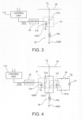
- the number 18a indicates the control winding or solenoid of the solenoid brake release valve 18 of one of the diagrams shown in Figures 1 and 2 .
- the winding or solenoid 18a has one terminal connected to an earth conductor GND and the other terminal connected to an electric emergency line or loop 20 on which, in a known way, during normal operation of the braking system of the railway vehicle, there is a voltage Vs, which drops when emergency braking is activated.
- the winding or solenoid 18a of the solenoid brake release valve is coupled to the line or loop 20 through a controlled electric switch, indicated as a whole by 21.
- the switch 21 is of the normally closed type, and in the embodiment shown by way of example in Figure 3 it is an electromechanical switch, comprising a normally closed contact 21a controlled by a winding or solenoid 21b, the latter being connected between the outlet of a driver circuit 22 and the earth conductor GND.
- the controlled switch 21 could alternatively be of a static type, for example a solid state electronic switch, controlled through a galvanic decoupling device such as an optical isolator.
- a control unit 113 (which may or may not be the unit 13 described above) applies a vital signal to the input of the drive circuit or driver 22 such that said drive circuit 22 keeps the solenoid 21b energized, so that the latter holds the associated movable contact 21a in the open position, thereby keeping the winding or solenoid 18a of the solenoid brake release valve 18 de-energized.
- the brake release valve 18 does not interfere with the normal operation of the braking system.
- FIG. 4 shows a variant embodiment.
- parts and elements described previously have again been given the alphanumeric references used previously.
- the brake release valve 18 can be energized either as a result of the disappearance of the vital signal at the input of the drive circuit 22, or in consequence of a request activated by the driver or by a control logic of the vehicle, through a normally open switch 30, connected in a circuit which controls the energization of a second controlled switch device 121.
- the switch 121 is also of the electromechanical type, and comprises a normally open movable contact 121a connected in parallel to the normally closed contact 21a of the switch 21.
- the switch 121 further comprises a winding or solenoid 121b which controls the position of the movable contact 121a, and which can be coupled via the switch 30 to a source 31 of an energizing voltage V E .
- control chamber 14 of the relay valve 15 is emptied virtually immediately, and the brake is released, preventing any risk of locking.
Landscapes
- Engineering & Computer Science (AREA)
- Transportation (AREA)
- Mechanical Engineering (AREA)
- Braking Systems And Boosters (AREA)
- Valves And Accessory Devices For Braking Systems (AREA)
- Regulating Braking Force (AREA)
Claims (2)
- Pneumatisches Bremssystem für ein Schienenfahrzeug, mit einem pneumatischen Schaltkreis zum Leiten eines pneumatischen Bremsdrucks zu wenigstens einem Bremszylinder (16), aufweisendein pneumatisches Magnetladeventil (11) und ein pneumatisches Magnetlöseventil (12), die zum Hervorrufen eines Anstiegs bzw. einer Reduzierung des pneumatischen Drucks, der auf den wenigstens einen Bremszylinder (16) wirkt, angepasst sind, wobei die Magnetventile (11, 12) von einer elektronischen Bremssteuereinheit (13) gesteuert werden;ein Magnetbremse-Entlastungsventil (18), das, wenn mit Energie beaufschlagt, zum Hervorrufen eines vollständigen Ablassens des pneumatischen Drucks, der auf den wenigstens einen Bremszylinder (16) aufgebracht wird, unabhängig von den Zuständen des Magnetlade- und -löseventils (11, 12) angepasst ist;das System ferner eine elektrische Notfallleitung (20) aufweist, auf der in einem normalen Betrieb eine Spannung (VE) vorhanden ist, die abfällt, wenn eine Notbremsung aktiviert wird;das Magnetbremse-Entlastungsventil (18) mit der elektrischen Notfallleitung (20) durch wenigstens einen gesteuerten elektrischen Schalter (21) gekoppelt ist, so dassdas Magnetbremse-Entlastungsventil (18) durch ein gesteuertes Schließen des Schalters (21) mit Energie beaufschlagt werden kann, wenn eine Spannung (VE) auf der elektrischen Notfallleitung (20) vorhanden ist unddas Magnetbremse-Entlastungsventil (18) nicht länger mit Energie beaufschlagt wird, wenn der Schalter (21) geöffnet wird sowie wenn die Spannung (VE) auf der elektrischen Notfallleitung (20) abfällt, unabhängig von dem Zustand des Schalters (21);wobei der wenigstens eine gesteuerte Schalter (21) ein üblicherweise geschlossener Typ ist und mit Steuermitteln (113, 22) verbunden ist, die zum Leiten eines Sperrsignals dorthin ausgelegt sind, das geeignet ist, den Schalter in einem normalen Betriebszustand des Systems offen zu halten und das Sperrsignal auszuschalten und das Schließen des Schalters (21) in einem Zustand einer Störung oder eines Fehlers zu ermöglichenwobei das System dadurch gekennzeichnet ist, dassdas Steuermittel eine Treiberschaltung oder einen Treiber (22) enthält und die elektronischen Bremssteuereinheit (13) eingerichtet ist für:- in einem normalen Betriebszustand des Bremssystems ein Lebenssignal an einen Eingang der Treiberschaltung oder des Treibers (22) anzulegen, so dass die Treiberschaltung oder der Treiber (22) den gesteuerten Schalter (21) offen hält, wodurch das Magnetbremse-Entlastungsventil (18) stromlos gehalten wird;- in einem Zustand der Fehlfunktion oder des Ausfalls des Bremssystems, Unterbrechung des Anlegens des Lebenssignal an den Eingang der Treiberschaltung oder des Treibers (22), so dass die Treiberschaltung oder der Treiber (22) dem gesteuerten Schalter (21) erlaubt, in seinen normalen geschlossenen Zustand zurückzukehren.
- Pneumatisches Bremssystem nach Anspruch 1, wobei parallel zu dem wenigstens einen Schalter (21) wenigstens ein zweiter gesteuerter elektrischer Schalter (121) eines üblicherweise offenen Typs verbunden ist, der angepasst ist, dass er zum Bewirken der Energiebeaufschlagung des Magnetbremse-Entlastungsventils (18) als eine Folge des Schließens eines zugeordneten Schalters (30), der von einem Zugführer und/oder einem elektronischen Steuersystem gesteuert werden kann, geschlossen wird.
Applications Claiming Priority (2)
| Application Number | Priority Date | Filing Date | Title |
|---|---|---|---|
| ITUB2015A002413A ITUB20152413A1 (it) | 2015-07-22 | 2015-07-22 | Sistema pneumatico di frenatura per un veicolo ferroviario, con elettrovalvola di rilascio della frenatura. |
| PCT/IB2016/054331 WO2017013610A1 (en) | 2015-07-22 | 2016-07-21 | Pneumatic braking system for a railway vehicle with a solenoid brake release valve |
Publications (3)
| Publication Number | Publication Date |
|---|---|
| EP3325320A1 EP3325320A1 (de) | 2018-05-30 |
| EP3325320B1 EP3325320B1 (de) | 2019-04-24 |
| EP3325320B2 true EP3325320B2 (de) | 2023-05-10 |
Family
ID=54542335
Family Applications (1)
| Application Number | Title | Priority Date | Filing Date |
|---|---|---|---|
| EP16762863.5A Active EP3325320B2 (de) | 2015-07-22 | 2016-07-21 | Pneumatisches bremssystem für ein schienenfahrzeug mit einem bremslösemagnetventil |
Country Status (9)
| Country | Link |
|---|---|
| US (1) | US10486672B2 (de) |
| EP (1) | EP3325320B2 (de) |
| JP (1) | JP6959217B2 (de) |
| CN (1) | CN108137024B (de) |
| BR (1) | BR112018001250B1 (de) |
| ES (1) | ES2737826T5 (de) |
| IT (1) | ITUB20152413A1 (de) |
| RU (1) | RU2729871C2 (de) |
| WO (1) | WO2017013610A1 (de) |
Families Citing this family (5)
| Publication number | Priority date | Publication date | Assignee | Title |
|---|---|---|---|---|
| US12509037B2 (en) * | 2014-11-13 | 2025-12-30 | Faiveley Transport Italia S.P.A. | Vehicle braking assembly |
| ES2966682T3 (es) * | 2018-09-11 | 2024-04-23 | Knorr Bremse Systeme | Sistema de freno |
| JP7092084B2 (ja) * | 2019-04-03 | 2022-06-28 | トヨタ自動車株式会社 | ブレーキシステム |
| CN113767039B (zh) * | 2019-04-30 | 2024-09-13 | 法伊韦利传送器意大利有限公司 | 铁路车辆或列车的至少一个车轴的旋转监测系统 |
| US11718281B2 (en) * | 2020-12-01 | 2023-08-08 | Faiveley Transport Rail Technologies India Private Limited | Brake control system |
Family Cites Families (24)
| Publication number | Priority date | Publication date | Assignee | Title |
|---|---|---|---|---|
| DE3408013A1 (de) * | 1984-03-05 | 1985-09-12 | Knorr-Bremse GmbH, 8000 München | Notbremseinrichtung fuer indirekt wirkende druckluftbremsen von schienenfahrzeug-zuegen |
| JPS61253255A (ja) * | 1985-04-30 | 1986-11-11 | Nippon Air Brake Co Ltd | 鉄道車両用非常ブレ−キ指令読換装置 |
| US5222788A (en) * | 1991-09-16 | 1993-06-29 | Westinghouse Air Brake Company | Microprocessor based electro-pneumatic locomotive brake control system having brake assurance circuit |
| US5332297A (en) | 1993-04-26 | 1994-07-26 | Westinghouse Air Brake Company | Charging cut-off valve arrangement for microprocessor-based electropneumatic locomotive brake control system |
| US5503469A (en) | 1995-01-30 | 1996-04-02 | Westinghouse Air Brake Company | Apparatus to prevent inadvertent discharge and trapping of pipe pressure in an electro-pneumatic locomotive brake control system |
| US6286913B1 (en) * | 1995-11-09 | 2001-09-11 | Westinghouse Air Brake Company | Limp-in control arrangement for an electro-pneumatic brake control system |
| US5791744A (en) * | 1997-01-28 | 1998-08-11 | Westinghouse Air Brake Company | Pneumatic trainline control unit |
| US5984426A (en) | 1997-07-31 | 1999-11-16 | Westinghouse Air Brake Company | Apparatus and method for a railway freight car brake control |
| US6472769B1 (en) | 2000-09-14 | 2002-10-29 | New York Air Brake Corporation | Car control device assembly |
| DE10135797C2 (de) * | 2001-07-23 | 2003-05-22 | Knorr Bremse Systeme | Bremssteuervorrichtung für Schienenfahrzeuge, die mit einer elektrischen Bremse und einer pneumatischen Bremse ausgestattet sind |
| US20040119331A1 (en) * | 2002-12-20 | 2004-06-24 | Knorr Brake Corporation | Electropneumatic brake control system |
| DE10342017B3 (de) | 2003-09-11 | 2004-09-30 | Siemens Ag | Schienenfahrzeug mit elektrischer Signalleitungsschleife |
| DE102004024462A1 (de) | 2004-05-14 | 2005-12-08 | Knorr-Bremse Systeme für Schienenfahrzeuge GmbH | Elektropneumatische Bremseinrichtung eines Schienenfahrzeugs mit durchgängigem Regelbereich |
| DE102008012700B3 (de) | 2008-03-05 | 2009-06-04 | Knorr-Bremse Systeme für Schienenfahrzeuge GmbH | Elektropneumatische Bremseinrichtung mit lastkorrigierter Bremsdruckregelung |
| CN102099233B (zh) * | 2008-07-24 | 2013-10-23 | 三菱电机株式会社 | 列车制动装置 |
| CN102159433B (zh) | 2008-09-22 | 2013-11-06 | 纳博特斯克株式会社 | 随重调整阀及制动控制装置 |
| EP2165902B1 (de) | 2008-09-22 | 2011-09-07 | Bombardier Transportation GmbH | Schienenfahrzeug-Elektropneumatikbremssystem und Schienenfahrzeug mit diesem System |
| JP5244557B2 (ja) * | 2008-11-25 | 2013-07-24 | ナブテスコ株式会社 | ブレーキ制御装置 |
| ES2413501T3 (es) | 2008-10-21 | 2013-07-16 | Mitsubishi Electric Corporation | Dispositivo de control de freno para vehículo ferroviario |
| CN102666245B (zh) | 2009-11-25 | 2015-06-17 | 三菱电机株式会社 | 制动控制装置 |
| GB2502252B (en) * | 2012-03-26 | 2018-09-05 | Knorr Bremse Rail Systems Uk Ltd | Emergency braking |
| DE102012009427B4 (de) | 2012-05-11 | 2013-11-21 | Knorr-Bremse Systeme für Schienenfahrzeuge GmbH | Steuerventileinrichtung für eine Schienenfahrzeugbremse |
| AU2013205185B2 (en) * | 2012-06-07 | 2015-11-26 | Faiveley Transport Australia Ltd | Park Brake Control Assembly |
| DE102013224421A1 (de) | 2013-11-28 | 2015-05-28 | Siemens Aktiengesellschaft | Bremssystem und Verfahren zum Steuern eines Bremssystems |
-
2015
- 2015-07-22 IT ITUB2015A002413A patent/ITUB20152413A1/it unknown
-
2016
- 2016-07-21 WO PCT/IB2016/054331 patent/WO2017013610A1/en not_active Ceased
- 2016-07-21 CN CN201680042878.9A patent/CN108137024B/zh active Active
- 2016-07-21 ES ES16762863T patent/ES2737826T5/es active Active
- 2016-07-21 RU RU2018106343A patent/RU2729871C2/ru active
- 2016-07-21 EP EP16762863.5A patent/EP3325320B2/de active Active
- 2016-07-21 JP JP2018502732A patent/JP6959217B2/ja active Active
- 2016-07-21 US US15/746,260 patent/US10486672B2/en active Active
- 2016-07-21 BR BR112018001250-5A patent/BR112018001250B1/pt active IP Right Grant
Also Published As
| Publication number | Publication date |
|---|---|
| RU2018106343A3 (de) | 2020-01-29 |
| BR112018001250B1 (pt) | 2023-01-24 |
| CN108137024A (zh) | 2018-06-08 |
| ITUB20152413A1 (it) | 2017-01-22 |
| US20180215365A1 (en) | 2018-08-02 |
| RU2729871C2 (ru) | 2020-08-12 |
| BR112018001250A2 (pt) | 2018-09-18 |
| ES2737826T5 (es) | 2023-08-10 |
| EP3325320B1 (de) | 2019-04-24 |
| WO2017013610A1 (en) | 2017-01-26 |
| ES2737826T3 (es) | 2020-01-16 |
| JP6959217B2 (ja) | 2021-11-02 |
| US10486672B2 (en) | 2019-11-26 |
| EP3325320A1 (de) | 2018-05-30 |
| JP2018523605A (ja) | 2018-08-23 |
| CN108137024B (zh) | 2021-02-26 |
| RU2018106343A (ru) | 2019-08-22 |
Similar Documents
| Publication | Publication Date | Title |
|---|---|---|
| EP3325320B2 (de) | Pneumatisches bremssystem für ein schienenfahrzeug mit einem bremslösemagnetventil | |
| CN111801254B (zh) | 车辆的电气动装备 | |
| US9944266B2 (en) | Electropneumatic brake control device with automatic ventilation of the spring applied brake in the event of a power loss | |
| US9555788B2 (en) | Motor vehicle | |
| US20240246520A1 (en) | Method for operating an electropneumatic brake system, fail-safety valve unit, electropneumatic brake system and vehicle | |
| GB2176857A (en) | Electropneumatic brake system for a railway vehicle | |
| CN112533805B (zh) | 具有关断阀的电气动的停驻制动设施以及用于对受电子控制的气动制动系统进行控制的方法 | |
| CN105035058A (zh) | 电的驻车制动器 | |
| US20250083648A1 (en) | Method and device for safely braking a trailer | |
| EP3691941B1 (de) | Umgehung des luftzufuhrschutzes für ein elektronisches parkbremssystem und fahrzeug mit solch einem system | |
| US20140060667A1 (en) | Compressed Air Supply Device for Commercial Vehicles | |
| EP3962791B1 (de) | Drehüberwachungssystem mindestens einer achse für ein schienenfahrzeug oder einen zug | |
| CN117597279A (zh) | 具有自保持的安全阀的电动气动阀设施 | |
| EP1547888B1 (de) | Bremssystem für ein angetriebenes Schienenfahrzeug mit Antiblockiereinrichtung | |
| AU2013401431A1 (en) | Method for braking a rail vehicle and open-loop and/or closed-loop control device for a brake system | |
| CN113853326B (zh) | 用于气动制动系统的紧急制动阀系统 | |
| CN116457253B (zh) | 电动气动手制动系统 | |
| RU2777384C1 (ru) | Устройство экстренного торможения для рельсового транспортного средства | |
| EA043777B1 (ru) | Система контроля вращения по меньшей мере одной оси для железнодорожного транспортного средства или поезда |
Legal Events
| Date | Code | Title | Description |
|---|---|---|---|
| STAA | Information on the status of an ep patent application or granted ep patent |
Free format text: STATUS: THE INTERNATIONAL PUBLICATION HAS BEEN MADE |
|
| PUAI | Public reference made under article 153(3) epc to a published international application that has entered the european phase |
Free format text: ORIGINAL CODE: 0009012 |
|
| STAA | Information on the status of an ep patent application or granted ep patent |
Free format text: STATUS: REQUEST FOR EXAMINATION WAS MADE |
|
| 17P | Request for examination filed |
Effective date: 20180118 |
|
| AK | Designated contracting states |
Kind code of ref document: A1 Designated state(s): AL AT BE BG CH CY CZ DE DK EE ES FI FR GB GR HR HU IE IS IT LI LT LU LV MC MK MT NL NO PL PT RO RS SE SI SK SM TR |
|
| AX | Request for extension of the european patent |
Extension state: BA ME |
|
| DAV | Request for validation of the european patent (deleted) | ||
| DAX | Request for extension of the european patent (deleted) | ||
| GRAP | Despatch of communication of intention to grant a patent |
Free format text: ORIGINAL CODE: EPIDOSNIGR1 |
|
| STAA | Information on the status of an ep patent application or granted ep patent |
Free format text: STATUS: GRANT OF PATENT IS INTENDED |
|
| INTG | Intention to grant announced |
Effective date: 20181115 |
|
| GRAS | Grant fee paid |
Free format text: ORIGINAL CODE: EPIDOSNIGR3 |
|
| GRAA | (expected) grant |
Free format text: ORIGINAL CODE: 0009210 |
|
| STAA | Information on the status of an ep patent application or granted ep patent |
Free format text: STATUS: THE PATENT HAS BEEN GRANTED |
|
| AK | Designated contracting states |
Kind code of ref document: B1 Designated state(s): AL AT BE BG CH CY CZ DE DK EE ES FI FR GB GR HR HU IE IS IT LI LT LU LV MC MK MT NL NO PL PT RO RS SE SI SK SM TR |
|
| REG | Reference to a national code |
Ref country code: GB Ref legal event code: FG4D |
|
| REG | Reference to a national code |
Ref country code: CH Ref legal event code: EP |
|
| REG | Reference to a national code |
Ref country code: AT Ref legal event code: REF Ref document number: 1123772 Country of ref document: AT Kind code of ref document: T Effective date: 20190515 Ref country code: IE Ref legal event code: FG4D |
|
| REG | Reference to a national code |
Ref country code: DE Ref legal event code: R096 Ref document number: 602016012946 Country of ref document: DE |
|
| REG | Reference to a national code |
Ref country code: NL Ref legal event code: MP Effective date: 20190424 |
|
| REG | Reference to a national code |
Ref country code: LT Ref legal event code: MG4D |
|
| PG25 | Lapsed in a contracting state [announced via postgrant information from national office to epo] |
Ref country code: NL Free format text: LAPSE BECAUSE OF FAILURE TO SUBMIT A TRANSLATION OF THE DESCRIPTION OR TO PAY THE FEE WITHIN THE PRESCRIBED TIME-LIMIT Effective date: 20190424 |
|
| PG25 | Lapsed in a contracting state [announced via postgrant information from national office to epo] |
Ref country code: SE Free format text: LAPSE BECAUSE OF FAILURE TO SUBMIT A TRANSLATION OF THE DESCRIPTION OR TO PAY THE FEE WITHIN THE PRESCRIBED TIME-LIMIT Effective date: 20190424 Ref country code: PT Free format text: LAPSE BECAUSE OF FAILURE TO SUBMIT A TRANSLATION OF THE DESCRIPTION OR TO PAY THE FEE WITHIN THE PRESCRIBED TIME-LIMIT Effective date: 20190824 Ref country code: HR Free format text: LAPSE BECAUSE OF FAILURE TO SUBMIT A TRANSLATION OF THE DESCRIPTION OR TO PAY THE FEE WITHIN THE PRESCRIBED TIME-LIMIT Effective date: 20190424 Ref country code: LT Free format text: LAPSE BECAUSE OF FAILURE TO SUBMIT A TRANSLATION OF THE DESCRIPTION OR TO PAY THE FEE WITHIN THE PRESCRIBED TIME-LIMIT Effective date: 20190424 Ref country code: NO Free format text: LAPSE BECAUSE OF FAILURE TO SUBMIT A TRANSLATION OF THE DESCRIPTION OR TO PAY THE FEE WITHIN THE PRESCRIBED TIME-LIMIT Effective date: 20190724 Ref country code: AL Free format text: LAPSE BECAUSE OF FAILURE TO SUBMIT A TRANSLATION OF THE DESCRIPTION OR TO PAY THE FEE WITHIN THE PRESCRIBED TIME-LIMIT Effective date: 20190424 Ref country code: FI Free format text: LAPSE BECAUSE OF FAILURE TO SUBMIT A TRANSLATION OF THE DESCRIPTION OR TO PAY THE FEE WITHIN THE PRESCRIBED TIME-LIMIT Effective date: 20190424 |
|
| PG25 | Lapsed in a contracting state [announced via postgrant information from national office to epo] |
Ref country code: PL Free format text: LAPSE BECAUSE OF FAILURE TO SUBMIT A TRANSLATION OF THE DESCRIPTION OR TO PAY THE FEE WITHIN THE PRESCRIBED TIME-LIMIT Effective date: 20190424 Ref country code: RS Free format text: LAPSE BECAUSE OF FAILURE TO SUBMIT A TRANSLATION OF THE DESCRIPTION OR TO PAY THE FEE WITHIN THE PRESCRIBED TIME-LIMIT Effective date: 20190424 Ref country code: LV Free format text: LAPSE BECAUSE OF FAILURE TO SUBMIT A TRANSLATION OF THE DESCRIPTION OR TO PAY THE FEE WITHIN THE PRESCRIBED TIME-LIMIT Effective date: 20190424 Ref country code: GR Free format text: LAPSE BECAUSE OF FAILURE TO SUBMIT A TRANSLATION OF THE DESCRIPTION OR TO PAY THE FEE WITHIN THE PRESCRIBED TIME-LIMIT Effective date: 20190725 Ref country code: BG Free format text: LAPSE BECAUSE OF FAILURE TO SUBMIT A TRANSLATION OF THE DESCRIPTION OR TO PAY THE FEE WITHIN THE PRESCRIBED TIME-LIMIT Effective date: 20190724 |
|
| REG | Reference to a national code |
Ref country code: AT Ref legal event code: MK05 Ref document number: 1123772 Country of ref document: AT Kind code of ref document: T Effective date: 20190424 |
|
| PG25 | Lapsed in a contracting state [announced via postgrant information from national office to epo] |
Ref country code: IS Free format text: LAPSE BECAUSE OF FAILURE TO SUBMIT A TRANSLATION OF THE DESCRIPTION OR TO PAY THE FEE WITHIN THE PRESCRIBED TIME-LIMIT Effective date: 20190824 |
|
| REG | Reference to a national code |
Ref country code: ES Ref legal event code: FG2A Ref document number: 2737826 Country of ref document: ES Kind code of ref document: T3 Effective date: 20200116 |
|
| REG | Reference to a national code |
Ref country code: DE Ref legal event code: R026 Ref document number: 602016012946 Country of ref document: DE |
|
| PG25 | Lapsed in a contracting state [announced via postgrant information from national office to epo] |
Ref country code: DK Free format text: LAPSE BECAUSE OF FAILURE TO SUBMIT A TRANSLATION OF THE DESCRIPTION OR TO PAY THE FEE WITHIN THE PRESCRIBED TIME-LIMIT Effective date: 20190424 Ref country code: AT Free format text: LAPSE BECAUSE OF FAILURE TO SUBMIT A TRANSLATION OF THE DESCRIPTION OR TO PAY THE FEE WITHIN THE PRESCRIBED TIME-LIMIT Effective date: 20190424 Ref country code: SK Free format text: LAPSE BECAUSE OF FAILURE TO SUBMIT A TRANSLATION OF THE DESCRIPTION OR TO PAY THE FEE WITHIN THE PRESCRIBED TIME-LIMIT Effective date: 20190424 Ref country code: CZ Free format text: LAPSE BECAUSE OF FAILURE TO SUBMIT A TRANSLATION OF THE DESCRIPTION OR TO PAY THE FEE WITHIN THE PRESCRIBED TIME-LIMIT Effective date: 20190424 Ref country code: RO Free format text: LAPSE BECAUSE OF FAILURE TO SUBMIT A TRANSLATION OF THE DESCRIPTION OR TO PAY THE FEE WITHIN THE PRESCRIBED TIME-LIMIT Effective date: 20190424 Ref country code: EE Free format text: LAPSE BECAUSE OF FAILURE TO SUBMIT A TRANSLATION OF THE DESCRIPTION OR TO PAY THE FEE WITHIN THE PRESCRIBED TIME-LIMIT Effective date: 20190424 |
|
| PLBI | Opposition filed |
Free format text: ORIGINAL CODE: 0009260 |
|
| PLAX | Notice of opposition and request to file observation + time limit sent |
Free format text: ORIGINAL CODE: EPIDOSNOBS2 |
|
| PG25 | Lapsed in a contracting state [announced via postgrant information from national office to epo] |
Ref country code: MC Free format text: LAPSE BECAUSE OF FAILURE TO SUBMIT A TRANSLATION OF THE DESCRIPTION OR TO PAY THE FEE WITHIN THE PRESCRIBED TIME-LIMIT Effective date: 20190424 Ref country code: SM Free format text: LAPSE BECAUSE OF FAILURE TO SUBMIT A TRANSLATION OF THE DESCRIPTION OR TO PAY THE FEE WITHIN THE PRESCRIBED TIME-LIMIT Effective date: 20190424 |
|
| REG | Reference to a national code |
Ref country code: CH Ref legal event code: PL |
|
| 26 | Opposition filed |
Opponent name: KNORR-BREMSE SYSTEME FUER SCHIENENFAHRZEUGE GMBH Effective date: 20200123 |
|
| PG25 | Lapsed in a contracting state [announced via postgrant information from national office to epo] |
Ref country code: TR Free format text: LAPSE BECAUSE OF FAILURE TO SUBMIT A TRANSLATION OF THE DESCRIPTION OR TO PAY THE FEE WITHIN THE PRESCRIBED TIME-LIMIT Effective date: 20190424 |
|
| REG | Reference to a national code |
Ref country code: BE Ref legal event code: MM Effective date: 20190731 |
|
| PG25 | Lapsed in a contracting state [announced via postgrant information from national office to epo] |
Ref country code: BE Free format text: LAPSE BECAUSE OF NON-PAYMENT OF DUE FEES Effective date: 20190731 Ref country code: CH Free format text: LAPSE BECAUSE OF NON-PAYMENT OF DUE FEES Effective date: 20190731 Ref country code: LI Free format text: LAPSE BECAUSE OF NON-PAYMENT OF DUE FEES Effective date: 20190731 Ref country code: SI Free format text: LAPSE BECAUSE OF FAILURE TO SUBMIT A TRANSLATION OF THE DESCRIPTION OR TO PAY THE FEE WITHIN THE PRESCRIBED TIME-LIMIT Effective date: 20190424 Ref country code: LU Free format text: LAPSE BECAUSE OF NON-PAYMENT OF DUE FEES Effective date: 20190721 |
|
| PLBB | Reply of patent proprietor to notice(s) of opposition received |
Free format text: ORIGINAL CODE: EPIDOSNOBS3 |
|
| PLAK | Information related to reply of patent proprietor to notice(s) of opposition modified |
Free format text: ORIGINAL CODE: EPIDOSCOBS3 |
|
| PG25 | Lapsed in a contracting state [announced via postgrant information from national office to epo] |
Ref country code: IE Free format text: LAPSE BECAUSE OF NON-PAYMENT OF DUE FEES Effective date: 20190721 |
|
| PG25 | Lapsed in a contracting state [announced via postgrant information from national office to epo] |
Ref country code: CY Free format text: LAPSE BECAUSE OF FAILURE TO SUBMIT A TRANSLATION OF THE DESCRIPTION OR TO PAY THE FEE WITHIN THE PRESCRIBED TIME-LIMIT Effective date: 20190424 |
|
| PG25 | Lapsed in a contracting state [announced via postgrant information from national office to epo] |
Ref country code: MT Free format text: LAPSE BECAUSE OF FAILURE TO SUBMIT A TRANSLATION OF THE DESCRIPTION OR TO PAY THE FEE WITHIN THE PRESCRIBED TIME-LIMIT Effective date: 20190424 Ref country code: HU Free format text: LAPSE BECAUSE OF FAILURE TO SUBMIT A TRANSLATION OF THE DESCRIPTION OR TO PAY THE FEE WITHIN THE PRESCRIBED TIME-LIMIT; INVALID AB INITIO Effective date: 20160721 |
|
| PG25 | Lapsed in a contracting state [announced via postgrant information from national office to epo] |
Ref country code: MK Free format text: LAPSE BECAUSE OF FAILURE TO SUBMIT A TRANSLATION OF THE DESCRIPTION OR TO PAY THE FEE WITHIN THE PRESCRIBED TIME-LIMIT Effective date: 20190424 |
|
| PUAH | Patent maintained in amended form |
Free format text: ORIGINAL CODE: 0009272 |
|
| STAA | Information on the status of an ep patent application or granted ep patent |
Free format text: STATUS: PATENT MAINTAINED AS AMENDED |
|
| 27A | Patent maintained in amended form |
Effective date: 20230510 |
|
| AK | Designated contracting states |
Kind code of ref document: B2 Designated state(s): AL AT BE BG CH CY CZ DE DK EE ES FI FR GB GR HR HU IE IS IT LI LT LU LV MC MK MT NL NO PL PT RO RS SE SI SK SM TR |
|
| REG | Reference to a national code |
Ref country code: DE Ref legal event code: R102 Ref document number: 602016012946 Country of ref document: DE |
|
| P01 | Opt-out of the competence of the unified patent court (upc) registered |
Effective date: 20230530 |
|
| REG | Reference to a national code |
Ref country code: ES Ref legal event code: DC2A Ref document number: 2737826 Country of ref document: ES Kind code of ref document: T5 Effective date: 20230810 |
|
| REG | Reference to a national code |
Ref country code: DE Ref legal event code: R082 Ref document number: 602016012946 Country of ref document: DE Representative=s name: ALPSPITZ IP ALLGAYER UND PARTNER PATENTANWAELT, DE |
|
| PGFP | Annual fee paid to national office [announced via postgrant information from national office to epo] |
Ref country code: ES Payment date: 20250822 Year of fee payment: 10 |
|
| PGFP | Annual fee paid to national office [announced via postgrant information from national office to epo] |
Ref country code: DE Payment date: 20250618 Year of fee payment: 10 |
|
| PGFP | Annual fee paid to national office [announced via postgrant information from national office to epo] |
Ref country code: IT Payment date: 20250618 Year of fee payment: 10 |
|
| PGFP | Annual fee paid to national office [announced via postgrant information from national office to epo] |
Ref country code: GB Payment date: 20250717 Year of fee payment: 10 |
|
| PGFP | Annual fee paid to national office [announced via postgrant information from national office to epo] |
Ref country code: FR Payment date: 20250722 Year of fee payment: 10 |