EP3325320B2 - Pneumatic braking system for a railway vehicle with a solenoid brake release valve - Google Patents
Pneumatic braking system for a railway vehicle with a solenoid brake release valve Download PDFInfo
- Publication number
- EP3325320B2 EP3325320B2 EP16762863.5A EP16762863A EP3325320B2 EP 3325320 B2 EP3325320 B2 EP 3325320B2 EP 16762863 A EP16762863 A EP 16762863A EP 3325320 B2 EP3325320 B2 EP 3325320B2
- Authority
- EP
- European Patent Office
- Prior art keywords
- solenoid
- switch
- pneumatic
- release valve
- controlled
- Prior art date
- Legal status (The legal status is an assumption and is not a legal conclusion. Google has not performed a legal analysis and makes no representation as to the accuracy of the status listed.)
- Active
Links
- 230000007257 malfunction Effects 0.000 claims 2
- 238000004804 winding Methods 0.000 description 10
- 238000010586 diagram Methods 0.000 description 7
- 239000004020 conductor Substances 0.000 description 2
- 230000004913 activation Effects 0.000 description 1
- 230000002547 anomalous effect Effects 0.000 description 1
- 238000010276 construction Methods 0.000 description 1
- 230000008034 disappearance Effects 0.000 description 1
- 230000002349 favourable effect Effects 0.000 description 1
- 230000003287 optical effect Effects 0.000 description 1
- 238000011084 recovery Methods 0.000 description 1
- 239000007787 solid Substances 0.000 description 1
- 230000003068 static effect Effects 0.000 description 1
Images

Classifications
-
- B—PERFORMING OPERATIONS; TRANSPORTING
- B60—VEHICLES IN GENERAL
- B60T—VEHICLE BRAKE CONTROL SYSTEMS OR PARTS THEREOF; BRAKE CONTROL SYSTEMS OR PARTS THEREOF, IN GENERAL; ARRANGEMENT OF BRAKING ELEMENTS ON VEHICLES IN GENERAL; PORTABLE DEVICES FOR PREVENTING UNWANTED MOVEMENT OF VEHICLES; VEHICLE MODIFICATIONS TO FACILITATE COOLING OF BRAKES
- B60T13/00—Transmitting braking action from initiating means to ultimate brake actuator with power assistance or drive; Brake systems incorporating such transmitting means, e.g. air-pressure brake systems
- B60T13/10—Transmitting braking action from initiating means to ultimate brake actuator with power assistance or drive; Brake systems incorporating such transmitting means, e.g. air-pressure brake systems with fluid assistance, drive, or release
- B60T13/66—Electrical control in fluid-pressure brake systems
- B60T13/68—Electrical control in fluid-pressure brake systems by electrically-controlled valves
- B60T13/683—Electrical control in fluid-pressure brake systems by electrically-controlled valves in pneumatic systems or parts thereof
-
- B—PERFORMING OPERATIONS; TRANSPORTING
- B60—VEHICLES IN GENERAL
- B60T—VEHICLE BRAKE CONTROL SYSTEMS OR PARTS THEREOF; BRAKE CONTROL SYSTEMS OR PARTS THEREOF, IN GENERAL; ARRANGEMENT OF BRAKING ELEMENTS ON VEHICLES IN GENERAL; PORTABLE DEVICES FOR PREVENTING UNWANTED MOVEMENT OF VEHICLES; VEHICLE MODIFICATIONS TO FACILITATE COOLING OF BRAKES
- B60T13/00—Transmitting braking action from initiating means to ultimate brake actuator with power assistance or drive; Brake systems incorporating such transmitting means, e.g. air-pressure brake systems
- B60T13/10—Transmitting braking action from initiating means to ultimate brake actuator with power assistance or drive; Brake systems incorporating such transmitting means, e.g. air-pressure brake systems with fluid assistance, drive, or release
- B60T13/66—Electrical control in fluid-pressure brake systems
- B60T13/68—Electrical control in fluid-pressure brake systems by electrically-controlled valves
-
- B—PERFORMING OPERATIONS; TRANSPORTING
- B60—VEHICLES IN GENERAL
- B60T—VEHICLE BRAKE CONTROL SYSTEMS OR PARTS THEREOF; BRAKE CONTROL SYSTEMS OR PARTS THEREOF, IN GENERAL; ARRANGEMENT OF BRAKING ELEMENTS ON VEHICLES IN GENERAL; PORTABLE DEVICES FOR PREVENTING UNWANTED MOVEMENT OF VEHICLES; VEHICLE MODIFICATIONS TO FACILITATE COOLING OF BRAKES
- B60T15/00—Construction arrangement, or operation of valves incorporated in power brake systems and not covered by groups B60T11/00 or B60T13/00
- B60T15/02—Application and release valves
- B60T15/021—Railway control or brake valves
-
- B—PERFORMING OPERATIONS; TRANSPORTING
- B60—VEHICLES IN GENERAL
- B60T—VEHICLE BRAKE CONTROL SYSTEMS OR PARTS THEREOF; BRAKE CONTROL SYSTEMS OR PARTS THEREOF, IN GENERAL; ARRANGEMENT OF BRAKING ELEMENTS ON VEHICLES IN GENERAL; PORTABLE DEVICES FOR PREVENTING UNWANTED MOVEMENT OF VEHICLES; VEHICLE MODIFICATIONS TO FACILITATE COOLING OF BRAKES
- B60T15/00—Construction arrangement, or operation of valves incorporated in power brake systems and not covered by groups B60T11/00 or B60T13/00
- B60T15/02—Application and release valves
- B60T15/025—Electrically controlled valves
- B60T15/027—Electrically controlled valves in pneumatic systems
-
- B—PERFORMING OPERATIONS; TRANSPORTING
- B60—VEHICLES IN GENERAL
- B60T—VEHICLE BRAKE CONTROL SYSTEMS OR PARTS THEREOF; BRAKE CONTROL SYSTEMS OR PARTS THEREOF, IN GENERAL; ARRANGEMENT OF BRAKING ELEMENTS ON VEHICLES IN GENERAL; PORTABLE DEVICES FOR PREVENTING UNWANTED MOVEMENT OF VEHICLES; VEHICLE MODIFICATIONS TO FACILITATE COOLING OF BRAKES
- B60T15/00—Construction arrangement, or operation of valves incorporated in power brake systems and not covered by groups B60T11/00 or B60T13/00
- B60T15/02—Application and release valves
- B60T15/04—Driver's valves
- B60T15/14—Driver's valves influencing electric control means
-
- B—PERFORMING OPERATIONS; TRANSPORTING
- B60—VEHICLES IN GENERAL
- B60T—VEHICLE BRAKE CONTROL SYSTEMS OR PARTS THEREOF; BRAKE CONTROL SYSTEMS OR PARTS THEREOF, IN GENERAL; ARRANGEMENT OF BRAKING ELEMENTS ON VEHICLES IN GENERAL; PORTABLE DEVICES FOR PREVENTING UNWANTED MOVEMENT OF VEHICLES; VEHICLE MODIFICATIONS TO FACILITATE COOLING OF BRAKES
- B60T17/00—Component parts, details, or accessories of power brake systems not covered by groups B60T8/00, B60T13/00 or B60T15/00, or presenting other characteristic features
- B60T17/18—Safety devices; Monitoring
- B60T17/22—Devices for monitoring or checking brake systems; Signal devices
- B60T17/228—Devices for monitoring or checking brake systems; Signal devices for railway vehicles
-
- B—PERFORMING OPERATIONS; TRANSPORTING
- B60—VEHICLES IN GENERAL
- B60T—VEHICLE BRAKE CONTROL SYSTEMS OR PARTS THEREOF; BRAKE CONTROL SYSTEMS OR PARTS THEREOF, IN GENERAL; ARRANGEMENT OF BRAKING ELEMENTS ON VEHICLES IN GENERAL; PORTABLE DEVICES FOR PREVENTING UNWANTED MOVEMENT OF VEHICLES; VEHICLE MODIFICATIONS TO FACILITATE COOLING OF BRAKES
- B60T2270/00—Further aspects of brake control systems not otherwise provided for
- B60T2270/40—Failsafe aspects of brake control systems
Definitions
- the present invention relates in a general way to a pneumatic braking system for a railway vehicle.
- the invention proposes a pneumatic braking system of the type comprising a pneumatic circuit for supplying a pneumatic braking pressure to at least one brake cylinder, including
- the numbers 11 and 12 indicate the solenoid charging and discharge valves, also known as solenoid filling and emptying valves, controlled by an electronic unit (ECU) 13. for modulating the pressure in the control chamber 14 of a relay valve 15, the outlet of which is connected to a brake cylinder 16.
- ECU electronic unit
- the solenoid valves 11 and 12 are of the three-way, two-position type, and in the de-energized state they are in the state shown in the drawing: the valve 11 allows a pressure to pass towards the control chamber 14 of the relay valve 15, and the valve 12 is closed.
- a further solenoid valve 18 is interposed between the solenoid valves 11 and 12, downstream of the branch 17 towards the relay valve 15, and causes, when energized, the total emptying of the control chamber 14 of the relay valve 15, regardless of the state of the solenoid valves 11 and 12. thereby causing the complete release of the brakes
- the solenoid release valve 18, which may be controlled by an electronic control unit or by a command given by the driver who is driving the railway train, is also a three-way, two-position valve: in the de-energized condition, shown in Figure 1 , it allows the pneumatic pressure received from the solenoid valve 11 to pass towards the control chamber 14 of the relay valve 15. When energized, however, the valve 18 couples the control chamber 14 of the relay valve 15 to the atmosphere, thus allowing this chamber to be rapidly emptied.
- Figure 2 shows another diagram according to the prior art, illustrating two variants: in a first variant, the solenoid brake release valve 18 is shown in solid lines, and is interposed between the branch 17 and the control chamber 14 of the relay valve 15, while in the second variant the solenoid valve 18, shown in broken lines, is interposed between the branch 17 and the inlet of the solenoid discharge or emptying valve 12.
- the pressure at the outlet of the charging valve 11 is sent to a brake cylinder without the use of a relay valve.
- the solenoid brake release valve 18 is energized as a result of a command given by the driver, or by an electronic control unit, in case it becomes necessary to disable the brake when the latter is jammed in the applied condition.
- the electro-pneumatic valves 11 and 12 may be designed as follows:
- the release valve 18, when energized, is kept in this condition until the portion of the braking system affected by the failure has been fully isolated. This solution prevents the use of the isolated braking portion, even if the emergency brake is subsequently applied, and consequently increases the stopping distance.
- US 6 286 913 B1 discloses a lamp-in control arrangement for an electro-pneumatic integrated control system for railway vehicles. However, the aforementioned problem still remains unsolved.
- EP 2 340 972 A1 discloses a brake control device with an emergency brake command line for effecting an emergency brake and a release solenoid valve electrically connected to said emergency brake command line through a shutoff circuit.
- One object of the present invention is therefore to provide a solution for overcoming the aforementioned drawbacks.
- the number 18a indicates the control winding or solenoid of the solenoid brake release valve 18 of one of the diagrams shown in Figures 1 and 2 .
- the winding or solenoid 18a has one terminal connected to an earth conductor GND and the other terminal connected to an electric emergency line or loop 20 on which, in a known way, during normal operation of the braking system of the railway vehicle, there is a voltage Vs, which drops when emergency braking is activated.
- the winding or solenoid 18a of the solenoid brake release valve is coupled to the line or loop 20 through a controlled electric switch, indicated as a whole by 21.
- the switch 21 is of the normally closed type, and in the embodiment shown by way of example in Figure 3 it is an electromechanical switch, comprising a normally closed contact 21a controlled by a winding or solenoid 21b, the latter being connected between the outlet of a driver circuit 22 and the earth conductor GND.
- the controlled switch 21 could alternatively be of a static type, for example a solid state electronic switch, controlled through a galvanic decoupling device such as an optical isolator.
- a control unit 113 (which may or may not be the unit 13 described above) applies a vital signal to the input of the drive circuit or driver 22 such that said drive circuit 22 keeps the solenoid 21b energized, so that the latter holds the associated movable contact 21a in the open position, thereby keeping the winding or solenoid 18a of the solenoid brake release valve 18 de-energized.
- the brake release valve 18 does not interfere with the normal operation of the braking system.
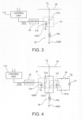
- FIG. 4 shows a variant embodiment.
- parts and elements described previously have again been given the alphanumeric references used previously.
- the brake release valve 18 can be energized either as a result of the disappearance of the vital signal at the input of the drive circuit 22, or in consequence of a request activated by the driver or by a control logic of the vehicle, through a normally open switch 30, connected in a circuit which controls the energization of a second controlled switch device 121.
- the switch 121 is also of the electromechanical type, and comprises a normally open movable contact 121a connected in parallel to the normally closed contact 21a of the switch 21.
- the switch 121 further comprises a winding or solenoid 121b which controls the position of the movable contact 121a, and which can be coupled via the switch 30 to a source 31 of an energizing voltage V E .
- control chamber 14 of the relay valve 15 is emptied virtually immediately, and the brake is released, preventing any risk of locking.
Description
- The present invention relates in a general way to a pneumatic braking system for a railway vehicle.
- More specifically, the invention proposes a pneumatic braking system of the type comprising a pneumatic circuit for supplying a pneumatic braking pressure to at least one brake cylinder, including
- a pneumatic solenoid charging valve and a pneumatic solenoid discharge valve adapted to cause an increase and a reduction, respectively, of the pneumatic pressure acting upon said at least one brake cylinder, said solenoid valves being controlled by an electronic braking control unit, and
- a solenoid brake release valve adapted to cause, when energized, a complete discharge of the pneumatic braking pressure applied to said at least one brake cylinder, independently of the conditions of said solenoid charging and discharge valves;
- the system comprising further an electric emergency line on which in normal operation there is a voltage which drops when emergency braking is activated.
- Various embodiments of a pneumatic braking system of the aforesaid type are schematically and partially illustrated in
Figures 1 and 2 of the attached drawings. - In particular, in
Figure 1 thenumbers control chamber 14 of arelay valve 15, the outlet of which is connected to abrake cylinder 16. - The
solenoid valves valve 11 allows a pressure to pass towards thecontrol chamber 14 of therelay valve 15, and thevalve 12 is closed. - In the diagram shown in
Figure 1 , afurther solenoid valve 18 is interposed between thesolenoid valves branch 17 towards therelay valve 15, and causes, when energized, the total emptying of thecontrol chamber 14 of therelay valve 15, regardless of the state of thesolenoid valves solenoid release valve 18, which may be controlled by an electronic control unit or by a command given by the driver who is driving the railway train, is also a three-way, two-position valve: in the de-energized condition, shown inFigure 1 , it allows the pneumatic pressure received from thesolenoid valve 11 to pass towards thecontrol chamber 14 of therelay valve 15. When energized, however, thevalve 18 couples thecontrol chamber 14 of therelay valve 15 to the atmosphere, thus allowing this chamber to be rapidly emptied. -
Figure 2 shows another diagram according to the prior art, illustrating two variants: in a first variant, the solenoidbrake release valve 18 is shown in solid lines, and is interposed between thebranch 17 and thecontrol chamber 14 of therelay valve 15, while in the second variant thesolenoid valve 18, shown in broken lines, is interposed between thebranch 17 and the inlet of the solenoid discharge or emptyingvalve 12. - In other known arrangements, not shown, the pressure at the outlet of the
charging valve 11 is sent to a brake cylinder without the use of a relay valve. - In the braking systems partially illustrated in
Figures 1 and 2 , the solenoidbrake release valve 18 is energized as a result of a command given by the driver, or by an electronic control unit, in case it becomes necessary to disable the brake when the latter is jammed in the applied condition. - Regarding the prior art, it should also be noted that, depending on the specifications provided by the railway operators concerning the behaviour of the braking system, the electro-
pneumatic valves - in a configuration known as "direct", in which the
valve 11, when de-energized, stops the inflow of pressurized air to thecontrol chamber 14 of the relay valve, and thevalve 12, when de-energized, empties thischamber 14 into the atmosphere, or - in a configuration known as "inverse", in which the
valve 11, when de-energized, allows the inflow of pressurized air to thecontrol chamber 14 of therelay valve 15, and thevalve 12, when de-energized, prevents the emptying of this control chamber into the atmosphere. - If the electronic control unit fails or is switched off, a "direct" configuration tends to empty the control chamber of the relay valve, thus causing the brake to be released, whereas an "inverse" configuration causes the brake to be applied with the maximum braking pressure.
- In an "inverse" configuration, therefore, there is a risk that, before the driver and/or the electronic control unit of the vehicle can decide to release the brake relating to the failed or switched-off electronic unit, the braking system will overheat and become damaged, or the wheels will jam while the vehicle is moving at speed, thus creating what are known as "flattened areas" or "flats" on the wheels. In this situation it would be convenient and desirable to be able to cause the release of the brake automatically before one of the problems described above can arise.
- In the arrangements according to the prior art described above, the
release valve 18, when energized, is kept in this condition until the portion of the braking system affected by the failure has been fully isolated. This solution prevents the use of the isolated braking portion, even if the emergency brake is subsequently applied, and consequently increases the stopping distance. - Consequently a solution allowing the recovery of the braking functionality of the pneumatic circuit in an emergency braking condition, during which the electric emergency line or loop is disabled, would be highly innovative and useful.
-
US 6 286 913 B1 discloses a lamp-in control arrangement for an electro-pneumatic integrated control system for railway vehicles. However, the aforementioned problem still remains unsolved.EP 2 340 972 A1 discloses a brake control device with an emergency brake command line for effecting an emergency brake and a release solenoid valve electrically connected to said emergency brake command line through a shutoff circuit. - One object of the present invention is therefore to provide a solution for overcoming the aforementioned drawbacks.
- This and other objects are achieved according to the invention with a pneumatic braking system according to claim 1.
- Further characteristics and advantages of the present invention will be apparent from the following detailed description, provided purely by way of non-limiting example, with reference to the attached drawings, in which:
-
Figures 1 and 2 , described above, are diagrams partially illustrating pneumatic braking systems according to the prior art; -
Figure 3 is an electrical diagram, partially in block form, showing a first solution according to the present invention; and -
Figure 4 is an electrical diagram, partially in block form, showing a second solution according to the present invention. - In
Figure 3 , thenumber 18a indicates the control winding or solenoid of the solenoidbrake release valve 18 of one of the diagrams shown inFigures 1 and 2 . - In the solution according to
Figure 3 , the winding orsolenoid 18a has one terminal connected to an earth conductor GND and the other terminal connected to an electric emergency line orloop 20 on which, in a known way, during normal operation of the braking system of the railway vehicle, there is a voltage Vs, which drops when emergency braking is activated. - The winding or
solenoid 18a of the solenoid brake release valve is coupled to the line or loop 20 through a controlled electric switch, indicated as a whole by 21. - The
switch 21 is of the normally closed type, and in the embodiment shown by way of example inFigure 3 it is an electromechanical switch, comprising a normally closedcontact 21a controlled by a winding orsolenoid 21b, the latter being connected between the outlet of adriver circuit 22 and the earth conductor GND. Evidently, the controlledswitch 21 could alternatively be of a static type, for example a solid state electronic switch, controlled through a galvanic decoupling device such as an optical isolator. - When the braking system operates normally, a control unit 113 (which may or may not be the
unit 13 described above) applies a vital signal to the input of the drive circuit ordriver 22 such that saiddrive circuit 22 keeps thesolenoid 21b energized, so that the latter holds the associatedmovable contact 21a in the open position, thereby keeping the winding orsolenoid 18a of the solenoidbrake release valve 18 de-energized. In this condition, with reference to the diagrams ofFigures 1 and 2 , thebrake release valve 18 does not interfere with the normal operation of the braking system. - If an operating anomaly or a failure occurs, as detected by the
control unit 113, it interrupts the application of the vital signal to the input of thedrive circuit 22, which consequently deenergizes the winding orsolenoid 21b of the controlledswitch 21, whosemovable contact 21a returns to the normal closed condition. The winding orsolenoid 18a of the solenoidbrake release valve 18 is then energized, and thissolenoid valve 18 causes the immediate emptying of the control or drive chamber of therelay valve 15, thus fully releasing the brake and preventing any risk of locking. - The system remains in this state unless the emergency line or
loop 20 is de-energized, in which case thesolenoid 18a of thebrake release valve 18 is then de-energized, returning the pneumatic braking system to the original condition. - This is found to be particularly favourable in the case of an "inverse" pneumatic configuration, since it restores the full braking force to the vehicle, including the portion relating to the electronic control unit in an anomalous or failed condition.
-
Figure 4 shows a variant embodiment. In this drawing, parts and elements described previously have again been given the alphanumeric references used previously. - In the solution according to
Figure 4 , thebrake release valve 18 can be energized either as a result of the disappearance of the vital signal at the input of thedrive circuit 22, or in consequence of a request activated by the driver or by a control logic of the vehicle, through a normallyopen switch 30, connected in a circuit which controls the energization of a second controlledswitch device 121. - In the illustrated embodiment, the
switch 121 is also of the electromechanical type, and comprises a normally openmovable contact 121a connected in parallel to the normally closedcontact 21a of theswitch 21. - The
switch 121 further comprises a winding orsolenoid 121b which controls the position of themovable contact 121a, and which can be coupled via theswitch 30 to asource 31 of an energizing voltage VE. - The closure of the normally
open switch 30, caused directly by the driver or by a control logic of the railway vehicle, causes the activation of the solenoid brake release valve 18: when theswitch 30 closes, the winding orsolenoid 121b of theswitch 121 is energized and causes the closure of themovable contact 121a and the consequent energizing of the winding orsolenoid 18a of thesolenoid release valve 18. - In this case also, the
control chamber 14 of therelay valve 15 is emptied virtually immediately, and the brake is released, preventing any risk of locking. - The system remains in this state unless the emergency line or
loop 20 is de-energized, in which case thesolenoid 18a of thebrake release valve 18 is then de-energized, returning the pneumatic braking system to the original condition.
In other respects, the solution shown inFigure 4 operates as described above in relation to the solution according toFigure 3 . - Naturally, the principle of the invention remaining the same, the forms of embodiment and the details of construction may be varied widely from what has been described and illustrated purely by way of non-limiting example, without thereby departing from the scope of the invention as defined by the attached claims.
Claims (2)
- Pneumatic braking system for a railway vehicle, comprising a pneumatic circuit for supplying a pneumatic braking pressure to at least one brake cylinder (16), includinga pneumatic solenoid charging valve (11) and a pneumatic solenoid discharge valve (12) adapted to cause an increase and a reduction, respectively, of the pneumatic pressure acting upon said at least one brake cylinder (16), said solenoid valves (11, 12) being controlled by an electronic braking control unit (13);a solenoid brake release valve (18) adapted to cause, when energized, a complete discharge of the pneumatic pressure applied to said at least one brake cylinder (16), independently of the conditions of said solenoid charging and discharge valves (11, 12);the system comprising further an electric emergency line (20) on which in normal operation there is a voltage (VE) which drops when emergency braking is activated;said solenoid brake release valve (18) is coupled to said electric emergency line (20) through at least one controlled electric switch (21), so thatthe solenoid brake release valve (18) can be energized by a controlled closure of said switch (21) when a voltage (VE) is present on said electric emergency line (20) andthe solenoid brake release valve (18) is de-energized when said switch (21) is opened, as well as when the voltage (VE) on the electric emergency line (20) drops, independently of the condition of said switch (21);wherein said at least one controlled switch (21) is of a normally closed type and is connected to control means (113, 22) designed to supply thereto a disabling signal, capable of keeping said switch open in a normal operating condition of the system and switching said disabling signal off and allowing the closure of said switch (21) in a condition of malfunction or failure;the system being characterized in thatthe control means includes a drive circuit or driver (22) and said electronic braking control unit (13) is arranged for:- in a normal operating condition of the braking system, applying a vital signal to an input of the drive circuit or driver (22), such that said drive circuit or driver (22) keeps said controlled switch (21) open thereby keeping the solenoid brake release valve (18) de-energized;- in a condition of malfunction or failure of the braking system, interrupting the application of the vital signal to the input of the drive circuit or driver (22), such that said drive circuit or driver (22) allows the controlled switch (21) to return in its normal closed condition.
- Pneumatic braking system according to Claim 1, wherein there is connected, in parallel with said at least one switch (21), at least one second controlled electric switch (121) of a normally open type, adapted to be closed to cause the energization of said solenoid brake release valve (18) as a consequence of the closure of an associated switch (30) that can be controlled by a train driver and/or an electronic control system.
Applications Claiming Priority (2)
| Application Number | Priority Date | Filing Date | Title |
|---|---|---|---|
| ITUB2015A002413A ITUB20152413A1 (en) | 2015-07-22 | 2015-07-22 | Pneumatic braking system for a railway vehicle, with brake release solenoid valve. |
| PCT/IB2016/054331 WO2017013610A1 (en) | 2015-07-22 | 2016-07-21 | Pneumatic braking system for a railway vehicle with a solenoid brake release valve |
Publications (3)
| Publication Number | Publication Date |
|---|---|
| EP3325320A1 EP3325320A1 (en) | 2018-05-30 |
| EP3325320B1 EP3325320B1 (en) | 2019-04-24 |
| EP3325320B2 true EP3325320B2 (en) | 2023-05-10 |
Family
ID=54542335
Family Applications (1)
| Application Number | Title | Priority Date | Filing Date |
|---|---|---|---|
| EP16762863.5A Active EP3325320B2 (en) | 2015-07-22 | 2016-07-21 | Pneumatic braking system for a railway vehicle with a solenoid brake release valve |
Country Status (9)
| Country | Link |
|---|---|
| US (1) | US10486672B2 (en) |
| EP (1) | EP3325320B2 (en) |
| JP (1) | JP6959217B2 (en) |
| CN (1) | CN108137024B (en) |
| BR (1) | BR112018001250B1 (en) |
| ES (1) | ES2737826T5 (en) |
| IT (1) | ITUB20152413A1 (en) |
| RU (1) | RU2729871C2 (en) |
| WO (1) | WO2017013610A1 (en) |
Families Citing this family (3)
| Publication number | Priority date | Publication date | Assignee | Title |
|---|---|---|---|---|
| EP3623236B1 (en) * | 2018-09-11 | 2023-11-08 | KNORR-BREMSE Systeme für Schienenfahrzeuge GmbH | Brake system |
| JP7092084B2 (en) * | 2019-04-03 | 2022-06-28 | トヨタ自動車株式会社 | Brake system |
| WO2020222120A1 (en) * | 2019-04-30 | 2020-11-05 | Faiveley Transport Italia S.P.A. | Rotational monitoring system of at least one axle for a railway vehicle or train |
Family Cites Families (22)
| Publication number | Priority date | Publication date | Assignee | Title |
|---|---|---|---|---|
| JPS61253255A (en) * | 1985-04-30 | 1986-11-11 | Nippon Air Brake Co Ltd | Emergency brake command interpreting device for railway vehicle |
| US5222788A (en) * | 1991-09-16 | 1993-06-29 | Westinghouse Air Brake Company | Microprocessor based electro-pneumatic locomotive brake control system having brake assurance circuit |
| US5332297A (en) | 1993-04-26 | 1994-07-26 | Westinghouse Air Brake Company | Charging cut-off valve arrangement for microprocessor-based electropneumatic locomotive brake control system |
| US5503469A (en) | 1995-01-30 | 1996-04-02 | Westinghouse Air Brake Company | Apparatus to prevent inadvertent discharge and trapping of pipe pressure in an electro-pneumatic locomotive brake control system |
| US6286913B1 (en) * | 1995-11-09 | 2001-09-11 | Westinghouse Air Brake Company | Limp-in control arrangement for an electro-pneumatic brake control system |
| US5791744A (en) * | 1997-01-28 | 1998-08-11 | Westinghouse Air Brake Company | Pneumatic trainline control unit |
| US5984426A (en) | 1997-07-31 | 1999-11-16 | Westinghouse Air Brake Company | Apparatus and method for a railway freight car brake control |
| US6472769B1 (en) | 2000-09-14 | 2002-10-29 | New York Air Brake Corporation | Car control device assembly |
| DE10135797C2 (en) * | 2001-07-23 | 2003-05-22 | Knorr Bremse Systeme | Brake control device for rail vehicles equipped with an electric brake and a pneumatic brake |
| US20040119331A1 (en) * | 2002-12-20 | 2004-06-24 | Knorr Brake Corporation | Electropneumatic brake control system |
| DE10342017B3 (en) | 2003-09-11 | 2004-09-30 | Siemens Ag | Railway vehicle with electrical signaling line loop for actuating its brakes has redundant safety loop that is electrically independent of remainder of vehicle control arrangement |
| DE102004024462A1 (en) | 2004-05-14 | 2005-12-08 | Knorr-Bremse Systeme für Schienenfahrzeuge GmbH | Electropneumatic brake device of a rail vehicle with continuous control range |
| DE102008012700B3 (en) | 2008-03-05 | 2009-06-04 | Knorr-Bremse Systeme für Schienenfahrzeuge GmbH | Electro-pneumatic brake unit i.e. load-sensitive emergency brake unit, for vehicle i.e. rail vehicle, has pressure regulator regulating/controlling emergency brake pre-control pressure to control valve, when emergency brake is applied |
| WO2010010623A1 (en) | 2008-07-24 | 2010-01-28 | 三菱電機株式会社 | Train braking device |
| WO2010032677A1 (en) | 2008-09-22 | 2010-03-25 | ナブテスコ株式会社 | Load compensating valve and brake control device |
| EP2165902B1 (en) | 2008-09-22 | 2011-09-07 | Bombardier Transportation GmbH | Rail vehicle electro-pneumatic brake system and a rail vehicle equipped with such system |
| CN102196951B (en) | 2008-10-21 | 2015-01-07 | 三菱电机株式会社 | Railcar brake control device |
| WO2011064851A1 (en) | 2009-11-25 | 2011-06-03 | 三菱電機株式会社 | Brake controller |
| GB2502252B (en) * | 2012-03-26 | 2018-09-05 | Knorr Bremse Rail Systems Uk Ltd | Emergency braking |
| DE102012009427B4 (en) | 2012-05-11 | 2013-11-21 | Knorr-Bremse Systeme für Schienenfahrzeuge GmbH | Control valve device for a rail vehicle brake |
| AU2013205185B2 (en) * | 2012-06-07 | 2015-11-26 | Faiveley Transport Australia Ltd | Park Brake Control Assembly |
| DE102013224421A1 (en) | 2013-11-28 | 2015-05-28 | Siemens Aktiengesellschaft | Brake system and method for controlling a brake system |
-
2015
- 2015-07-22 IT ITUB2015A002413A patent/ITUB20152413A1/en unknown
-
2016
- 2016-07-21 JP JP2018502732A patent/JP6959217B2/en active Active
- 2016-07-21 ES ES16762863T patent/ES2737826T5/en active Active
- 2016-07-21 WO PCT/IB2016/054331 patent/WO2017013610A1/en active Application Filing
- 2016-07-21 BR BR112018001250-5A patent/BR112018001250B1/en active IP Right Grant
- 2016-07-21 US US15/746,260 patent/US10486672B2/en active Active
- 2016-07-21 RU RU2018106343A patent/RU2729871C2/en active
- 2016-07-21 EP EP16762863.5A patent/EP3325320B2/en active Active
- 2016-07-21 CN CN201680042878.9A patent/CN108137024B/en active Active
Also Published As
| Publication number | Publication date |
|---|---|
| BR112018001250B1 (en) | 2023-01-24 |
| ES2737826T5 (en) | 2023-08-10 |
| CN108137024B (en) | 2021-02-26 |
| JP6959217B2 (en) | 2021-11-02 |
| EP3325320A1 (en) | 2018-05-30 |
| WO2017013610A1 (en) | 2017-01-26 |
| RU2018106343A3 (en) | 2020-01-29 |
| RU2729871C2 (en) | 2020-08-12 |
| EP3325320B1 (en) | 2019-04-24 |
| RU2018106343A (en) | 2019-08-22 |
| CN108137024A (en) | 2018-06-08 |
| US10486672B2 (en) | 2019-11-26 |
| ES2737826T3 (en) | 2020-01-16 |
| JP2018523605A (en) | 2018-08-23 |
| ITUB20152413A1 (en) | 2017-01-22 |
| US20180215365A1 (en) | 2018-08-02 |
| BR112018001250A2 (en) | 2018-09-18 |
Similar Documents
| Publication | Publication Date | Title |
|---|---|---|
| CN111801254B (en) | Electric equipment for vehicle | |
| CN101312864B (en) | Electro-pneumatic brake control device | |
| US9555788B2 (en) | Motor vehicle | |
| US9944266B2 (en) | Electropneumatic brake control device with automatic ventilation of the spring applied brake in the event of a power loss | |
| EP3325320B2 (en) | Pneumatic braking system for a railway vehicle with a solenoid brake release valve | |
| CN104487300A (en) | Emergency brake | |
| CN105035058A (en) | Electric parking brake | |
| US9140411B2 (en) | Compressed air supply device for commercial vehicles | |
| EP3691941B1 (en) | By-pass of air supply protection for electronic parking brake system and vehicle comprising such system | |
| KR20140006031A (en) | Multi-circuit protection valve for a compressed-air supply device of a vehicle, and method for operating a multi-circuit protection valve | |
| EP1547888B1 (en) | Braking system for a self-powered rail vehicle provided with an anti-slip device | |
| US11904827B2 (en) | Rotational monitoring system of at least one axle for a railway vehicle or train | |
| KR102643561B1 (en) | Emergency brake valve system for pneumatic braking systems | |
| AU2013401431A1 (en) | Method for braking a rail vehicle and open-loop and/or closed-loop control device for a brake system | |
| RU2777384C1 (en) | Emergency braking device for rail vehicle | |
| CN116457253A (en) | Electric pneumatic hand brake system | |
| CN116529134A (en) | Method for emergency application of a parking brake and electro-pneumatic brake system | |
| EA043777B1 (en) | ROTATION CONTROL SYSTEM ON AT LEAST ONE AXIS FOR RAILWAY VEHICLE OR TRAIN | |
| CN117597279A (en) | Electro-pneumatic valve installation with self-retaining safety valve |
Legal Events
| Date | Code | Title | Description |
|---|---|---|---|
| STAA | Information on the status of an ep patent application or granted ep patent |
Free format text: STATUS: THE INTERNATIONAL PUBLICATION HAS BEEN MADE |
|
| PUAI | Public reference made under article 153(3) epc to a published international application that has entered the european phase |
Free format text: ORIGINAL CODE: 0009012 |
|
| STAA | Information on the status of an ep patent application or granted ep patent |
Free format text: STATUS: REQUEST FOR EXAMINATION WAS MADE |
|
| 17P | Request for examination filed |
Effective date: 20180118 |
|
| AK | Designated contracting states |
Kind code of ref document: A1 Designated state(s): AL AT BE BG CH CY CZ DE DK EE ES FI FR GB GR HR HU IE IS IT LI LT LU LV MC MK MT NL NO PL PT RO RS SE SI SK SM TR |
|
| AX | Request for extension of the european patent |
Extension state: BA ME |
|
| DAV | Request for validation of the european patent (deleted) | ||
| DAX | Request for extension of the european patent (deleted) | ||
| GRAP | Despatch of communication of intention to grant a patent |
Free format text: ORIGINAL CODE: EPIDOSNIGR1 |
|
| STAA | Information on the status of an ep patent application or granted ep patent |
Free format text: STATUS: GRANT OF PATENT IS INTENDED |
|
| INTG | Intention to grant announced |
Effective date: 20181115 |
|
| GRAS | Grant fee paid |
Free format text: ORIGINAL CODE: EPIDOSNIGR3 |
|
| GRAA | (expected) grant |
Free format text: ORIGINAL CODE: 0009210 |
|
| STAA | Information on the status of an ep patent application or granted ep patent |
Free format text: STATUS: THE PATENT HAS BEEN GRANTED |
|
| AK | Designated contracting states |
Kind code of ref document: B1 Designated state(s): AL AT BE BG CH CY CZ DE DK EE ES FI FR GB GR HR HU IE IS IT LI LT LU LV MC MK MT NL NO PL PT RO RS SE SI SK SM TR |
|
| REG | Reference to a national code |
Ref country code: GB Ref legal event code: FG4D |
|
| REG | Reference to a national code |
Ref country code: CH Ref legal event code: EP |
|
| REG | Reference to a national code |
Ref country code: AT Ref legal event code: REF Ref document number: 1123772 Country of ref document: AT Kind code of ref document: T Effective date: 20190515 Ref country code: IE Ref legal event code: FG4D |
|
| REG | Reference to a national code |
Ref country code: DE Ref legal event code: R096 Ref document number: 602016012946 Country of ref document: DE |
|
| REG | Reference to a national code |
Ref country code: NL Ref legal event code: MP Effective date: 20190424 |
|
| REG | Reference to a national code |
Ref country code: LT Ref legal event code: MG4D |
|
| PG25 | Lapsed in a contracting state [announced via postgrant information from national office to epo] |
Ref country code: NL Free format text: LAPSE BECAUSE OF FAILURE TO SUBMIT A TRANSLATION OF THE DESCRIPTION OR TO PAY THE FEE WITHIN THE PRESCRIBED TIME-LIMIT Effective date: 20190424 |
|
| PG25 | Lapsed in a contracting state [announced via postgrant information from national office to epo] |
Ref country code: SE Free format text: LAPSE BECAUSE OF FAILURE TO SUBMIT A TRANSLATION OF THE DESCRIPTION OR TO PAY THE FEE WITHIN THE PRESCRIBED TIME-LIMIT Effective date: 20190424 Ref country code: PT Free format text: LAPSE BECAUSE OF FAILURE TO SUBMIT A TRANSLATION OF THE DESCRIPTION OR TO PAY THE FEE WITHIN THE PRESCRIBED TIME-LIMIT Effective date: 20190824 Ref country code: HR Free format text: LAPSE BECAUSE OF FAILURE TO SUBMIT A TRANSLATION OF THE DESCRIPTION OR TO PAY THE FEE WITHIN THE PRESCRIBED TIME-LIMIT Effective date: 20190424 Ref country code: LT Free format text: LAPSE BECAUSE OF FAILURE TO SUBMIT A TRANSLATION OF THE DESCRIPTION OR TO PAY THE FEE WITHIN THE PRESCRIBED TIME-LIMIT Effective date: 20190424 Ref country code: NO Free format text: LAPSE BECAUSE OF FAILURE TO SUBMIT A TRANSLATION OF THE DESCRIPTION OR TO PAY THE FEE WITHIN THE PRESCRIBED TIME-LIMIT Effective date: 20190724 Ref country code: AL Free format text: LAPSE BECAUSE OF FAILURE TO SUBMIT A TRANSLATION OF THE DESCRIPTION OR TO PAY THE FEE WITHIN THE PRESCRIBED TIME-LIMIT Effective date: 20190424 Ref country code: FI Free format text: LAPSE BECAUSE OF FAILURE TO SUBMIT A TRANSLATION OF THE DESCRIPTION OR TO PAY THE FEE WITHIN THE PRESCRIBED TIME-LIMIT Effective date: 20190424 |
|
| PG25 | Lapsed in a contracting state [announced via postgrant information from national office to epo] |
Ref country code: PL Free format text: LAPSE BECAUSE OF FAILURE TO SUBMIT A TRANSLATION OF THE DESCRIPTION OR TO PAY THE FEE WITHIN THE PRESCRIBED TIME-LIMIT Effective date: 20190424 Ref country code: RS Free format text: LAPSE BECAUSE OF FAILURE TO SUBMIT A TRANSLATION OF THE DESCRIPTION OR TO PAY THE FEE WITHIN THE PRESCRIBED TIME-LIMIT Effective date: 20190424 Ref country code: LV Free format text: LAPSE BECAUSE OF FAILURE TO SUBMIT A TRANSLATION OF THE DESCRIPTION OR TO PAY THE FEE WITHIN THE PRESCRIBED TIME-LIMIT Effective date: 20190424 Ref country code: GR Free format text: LAPSE BECAUSE OF FAILURE TO SUBMIT A TRANSLATION OF THE DESCRIPTION OR TO PAY THE FEE WITHIN THE PRESCRIBED TIME-LIMIT Effective date: 20190725 Ref country code: BG Free format text: LAPSE BECAUSE OF FAILURE TO SUBMIT A TRANSLATION OF THE DESCRIPTION OR TO PAY THE FEE WITHIN THE PRESCRIBED TIME-LIMIT Effective date: 20190724 |
|
| REG | Reference to a national code |
Ref country code: AT Ref legal event code: MK05 Ref document number: 1123772 Country of ref document: AT Kind code of ref document: T Effective date: 20190424 |
|
| PG25 | Lapsed in a contracting state [announced via postgrant information from national office to epo] |
Ref country code: IS Free format text: LAPSE BECAUSE OF FAILURE TO SUBMIT A TRANSLATION OF THE DESCRIPTION OR TO PAY THE FEE WITHIN THE PRESCRIBED TIME-LIMIT Effective date: 20190824 |
|
| REG | Reference to a national code |
Ref country code: ES Ref legal event code: FG2A Ref document number: 2737826 Country of ref document: ES Kind code of ref document: T3 Effective date: 20200116 |
|
| REG | Reference to a national code |
Ref country code: DE Ref legal event code: R026 Ref document number: 602016012946 Country of ref document: DE |
|
| PG25 | Lapsed in a contracting state [announced via postgrant information from national office to epo] |
Ref country code: DK Free format text: LAPSE BECAUSE OF FAILURE TO SUBMIT A TRANSLATION OF THE DESCRIPTION OR TO PAY THE FEE WITHIN THE PRESCRIBED TIME-LIMIT Effective date: 20190424 Ref country code: AT Free format text: LAPSE BECAUSE OF FAILURE TO SUBMIT A TRANSLATION OF THE DESCRIPTION OR TO PAY THE FEE WITHIN THE PRESCRIBED TIME-LIMIT Effective date: 20190424 Ref country code: SK Free format text: LAPSE BECAUSE OF FAILURE TO SUBMIT A TRANSLATION OF THE DESCRIPTION OR TO PAY THE FEE WITHIN THE PRESCRIBED TIME-LIMIT Effective date: 20190424 Ref country code: CZ Free format text: LAPSE BECAUSE OF FAILURE TO SUBMIT A TRANSLATION OF THE DESCRIPTION OR TO PAY THE FEE WITHIN THE PRESCRIBED TIME-LIMIT Effective date: 20190424 Ref country code: RO Free format text: LAPSE BECAUSE OF FAILURE TO SUBMIT A TRANSLATION OF THE DESCRIPTION OR TO PAY THE FEE WITHIN THE PRESCRIBED TIME-LIMIT Effective date: 20190424 Ref country code: EE Free format text: LAPSE BECAUSE OF FAILURE TO SUBMIT A TRANSLATION OF THE DESCRIPTION OR TO PAY THE FEE WITHIN THE PRESCRIBED TIME-LIMIT Effective date: 20190424 |
|
| PLBI | Opposition filed |
Free format text: ORIGINAL CODE: 0009260 |
|
| PLAX | Notice of opposition and request to file observation + time limit sent |
Free format text: ORIGINAL CODE: EPIDOSNOBS2 |
|
| PG25 | Lapsed in a contracting state [announced via postgrant information from national office to epo] |
Ref country code: MC Free format text: LAPSE BECAUSE OF FAILURE TO SUBMIT A TRANSLATION OF THE DESCRIPTION OR TO PAY THE FEE WITHIN THE PRESCRIBED TIME-LIMIT Effective date: 20190424 Ref country code: SM Free format text: LAPSE BECAUSE OF FAILURE TO SUBMIT A TRANSLATION OF THE DESCRIPTION OR TO PAY THE FEE WITHIN THE PRESCRIBED TIME-LIMIT Effective date: 20190424 |
|
| REG | Reference to a national code |
Ref country code: CH Ref legal event code: PL |
|
| 26 | Opposition filed |
Opponent name: KNORR-BREMSE SYSTEME FUER SCHIENENFAHRZEUGE GMBH Effective date: 20200123 |
|
| PG25 | Lapsed in a contracting state [announced via postgrant information from national office to epo] |
Ref country code: TR Free format text: LAPSE BECAUSE OF FAILURE TO SUBMIT A TRANSLATION OF THE DESCRIPTION OR TO PAY THE FEE WITHIN THE PRESCRIBED TIME-LIMIT Effective date: 20190424 |
|
| REG | Reference to a national code |
Ref country code: BE Ref legal event code: MM Effective date: 20190731 |
|
| PG25 | Lapsed in a contracting state [announced via postgrant information from national office to epo] |
Ref country code: BE Free format text: LAPSE BECAUSE OF NON-PAYMENT OF DUE FEES Effective date: 20190731 Ref country code: CH Free format text: LAPSE BECAUSE OF NON-PAYMENT OF DUE FEES Effective date: 20190731 Ref country code: LI Free format text: LAPSE BECAUSE OF NON-PAYMENT OF DUE FEES Effective date: 20190731 Ref country code: SI Free format text: LAPSE BECAUSE OF FAILURE TO SUBMIT A TRANSLATION OF THE DESCRIPTION OR TO PAY THE FEE WITHIN THE PRESCRIBED TIME-LIMIT Effective date: 20190424 Ref country code: LU Free format text: LAPSE BECAUSE OF NON-PAYMENT OF DUE FEES Effective date: 20190721 |
|
| PLBB | Reply of patent proprietor to notice(s) of opposition received |
Free format text: ORIGINAL CODE: EPIDOSNOBS3 |
|
| PLAK | Information related to reply of patent proprietor to notice(s) of opposition modified |
Free format text: ORIGINAL CODE: EPIDOSCOBS3 |
|
| PG25 | Lapsed in a contracting state [announced via postgrant information from national office to epo] |
Ref country code: IE Free format text: LAPSE BECAUSE OF NON-PAYMENT OF DUE FEES Effective date: 20190721 |
|
| PG25 | Lapsed in a contracting state [announced via postgrant information from national office to epo] |
Ref country code: CY Free format text: LAPSE BECAUSE OF FAILURE TO SUBMIT A TRANSLATION OF THE DESCRIPTION OR TO PAY THE FEE WITHIN THE PRESCRIBED TIME-LIMIT Effective date: 20190424 |
|
| PG25 | Lapsed in a contracting state [announced via postgrant information from national office to epo] |
Ref country code: MT Free format text: LAPSE BECAUSE OF FAILURE TO SUBMIT A TRANSLATION OF THE DESCRIPTION OR TO PAY THE FEE WITHIN THE PRESCRIBED TIME-LIMIT Effective date: 20190424 Ref country code: HU Free format text: LAPSE BECAUSE OF FAILURE TO SUBMIT A TRANSLATION OF THE DESCRIPTION OR TO PAY THE FEE WITHIN THE PRESCRIBED TIME-LIMIT; INVALID AB INITIO Effective date: 20160721 |
|
| PG25 | Lapsed in a contracting state [announced via postgrant information from national office to epo] |
Ref country code: MK Free format text: LAPSE BECAUSE OF FAILURE TO SUBMIT A TRANSLATION OF THE DESCRIPTION OR TO PAY THE FEE WITHIN THE PRESCRIBED TIME-LIMIT Effective date: 20190424 |
|
| PUAH | Patent maintained in amended form |
Free format text: ORIGINAL CODE: 0009272 |
|
| STAA | Information on the status of an ep patent application or granted ep patent |
Free format text: STATUS: PATENT MAINTAINED AS AMENDED |
|
| 27A | Patent maintained in amended form |
Effective date: 20230510 |
|
| AK | Designated contracting states |
Kind code of ref document: B2 Designated state(s): AL AT BE BG CH CY CZ DE DK EE ES FI FR GB GR HR HU IE IS IT LI LT LU LV MC MK MT NL NO PL PT RO RS SE SI SK SM TR |
|
| REG | Reference to a national code |
Ref country code: DE Ref legal event code: R102 Ref document number: 602016012946 Country of ref document: DE |
|
| P01 | Opt-out of the competence of the unified patent court (upc) registered |
Effective date: 20230530 |
|
| REG | Reference to a national code |
Ref country code: ES Ref legal event code: DC2A Ref document number: 2737826 Country of ref document: ES Kind code of ref document: T5 Effective date: 20230810 |
|
| REG | Reference to a national code |
Ref country code: DE Ref legal event code: R082 Ref document number: 602016012946 Country of ref document: DE Representative=s name: ALPSPITZ IP ALLGAYER UND PARTNER PATENTANWAELT, DE |
|
| PGFP | Annual fee paid to national office [announced via postgrant information from national office to epo] |
Ref country code: IT Payment date: 20230728 Year of fee payment: 8 Ref country code: GB Payment date: 20230721 Year of fee payment: 8 Ref country code: ES Payment date: 20230814 Year of fee payment: 8 |
|
| PGFP | Annual fee paid to national office [announced via postgrant information from national office to epo] |
Ref country code: FR Payment date: 20230725 Year of fee payment: 8 Ref country code: DE Payment date: 20230727 Year of fee payment: 8 |