EP3323942B1 - Modulare barriere leicht zu transportieren und zusammenzusetzen - Google Patents
Modulare barriere leicht zu transportieren und zusammenzusetzen Download PDFInfo
- Publication number
- EP3323942B1 EP3323942B1 EP17202269.1A EP17202269A EP3323942B1 EP 3323942 B1 EP3323942 B1 EP 3323942B1 EP 17202269 A EP17202269 A EP 17202269A EP 3323942 B1 EP3323942 B1 EP 3323942B1
- Authority
- EP
- European Patent Office
- Prior art keywords
- barrier
- poles
- pole
- vehicle
- ground
- Prior art date
- Legal status (The legal status is an assumption and is not a legal conclusion. Google has not performed a legal analysis and makes no representation as to the accuracy of the status listed.)
- Active
Links
Images


Classifications
-
- E—FIXED CONSTRUCTIONS
- E01—CONSTRUCTION OF ROADS, RAILWAYS, OR BRIDGES
- E01F—ADDITIONAL WORK, SUCH AS EQUIPPING ROADS OR THE CONSTRUCTION OF PLATFORMS, HELICOPTER LANDING STAGES, SIGNS, SNOW FENCES, OR THE LIKE
- E01F13/00—Arrangements for obstructing or restricting traffic, e.g. gates, barricades ; Preventing passage of vehicles of selected category or dimensions
- E01F13/12—Arrangements for obstructing or restricting traffic, e.g. gates, barricades ; Preventing passage of vehicles of selected category or dimensions for forcibly arresting or disabling vehicles, e.g. spiked mats
-
- E—FIXED CONSTRUCTIONS
- E01—CONSTRUCTION OF ROADS, RAILWAYS, OR BRIDGES
- E01F—ADDITIONAL WORK, SUCH AS EQUIPPING ROADS OR THE CONSTRUCTION OF PLATFORMS, HELICOPTER LANDING STAGES, SIGNS, SNOW FENCES, OR THE LIKE
- E01F13/00—Arrangements for obstructing or restricting traffic, e.g. gates, barricades ; Preventing passage of vehicles of selected category or dimensions
- E01F13/02—Arrangements for obstructing or restricting traffic, e.g. gates, barricades ; Preventing passage of vehicles of selected category or dimensions free-standing; portable, e.g. for guarding open manholes ; Portable signs or signals specially adapted for fitting to portable barriers
- E01F13/022—Pedestrian barriers; Barriers for channelling or controlling crowds
Definitions
- the present disclosed subject matter relates to heavy load modular vehicle barriers. More particularly, the present disclosed subject matter relates to portable barriers for easy and rapid transportation and assembly or disassembly.
- Road barriers are used to block roads for the purpose of hostile vehicle and crowd mitigation as well as controlling vehicular transportation. Control over roads is a security measure that is essential especially in the last decades. It is a necessity to have better control over roads barriers that can be transported and assembled in an easy and fast manner.
- a known vehicle barrier consisting of several modular units is disclosed in WO 2016/030886 .
- Each unit comprises a base bar and a reclining bar attached to it in a predetermined angle.
- the units are joined to each other by additional bars pivotally connected to the base and reclining bars.
- the disclosure relates to a building block in accordance with independent claim 1.
- the dependent claims relate to preferred embodiments.
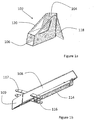
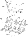
- FIGS 1a-c illustrating the connector and the poles, which are the building blocks of the modular barrier, and an exploded view of a connector and two poles that form a basic unit of a modular barrier, respectively, in accordance with exemplary embodiments of the disclosed subject matter.
- a basic unit 100 of the modular barrier as shown in Figure 1c in a disassembled state is made of three essential building blocks, two of the building blocks are preferably identical or substantially similar, a fact that makes the transportation and assembly of the barrier to be cost effective, rapid, and simple since only two building blocks are distinguishable.
- two building blocks are provided - a connector 102 (shown in Figure 1a ) that is preferably made of a bent tube of hard metal or several pieces of the hard metal welded together or connected together in any type of attachment as known in the art, to establish at least two but in this case two receiving pockets 104 and 106 that are configured to receive poles that will be, when inserted into the receiving pockets, angled in a predetermined angle that is more than 60° and preferably more than 90°.
- the second building block is a pole 108 that is shown in Figure 1b .
- Pole 108 has a profile that can be substantially square, triangular, or rectangular so as to render stability and strength to it; however, a rhombus profile is the preferable profile as will be explained herein after.
- Pole 108 can be a hollow pole or a solid pole, depending on the demand and needed strength. It is preferable that a free end 109 of pole 108 (the end of the pole that is not received within the receiving pocket) is diagonally cut and covered with a diagonal surface. As mentioned herein before, the preferred profile of the pole 108 is rhombus while it's preferable orientation on the ground is with a corner directed upwardly.
- Basic Unit 100 comprises a connecting bracket 102' that is preferably made of hasped metal plates of steel that is provided with two pockets 104' and 106' preferably having rhombus profile.
- Poles 108a and 108b are provided with a profile that is designed to correspond and be received within the pockets 104' and 106' of connecting bracket 102' and are preferably made of the same material as the connecting bracket.
- One end of the two poles, 108a and 108b is inserted within the corresponding pockets 104' and 106', respectively.
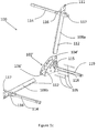
- FIG. 1d illustrating a view of the connecting bracket and the two poles assembled to form the basic unit of the modular barrier shown in Figure 1c .
- the pole 108a that is partially inserted into pocket 104' is in an upright position and the second pole 108b, which is partially inserted to within pocket 106', is parallel to the ground.
- the connecting bracket 102' itself has a profile that is also of substantially square or rectangular profile that is provided with a basis 103 that can be steadily placed on the ground with the pockets directed to the correct directions so as to have the poles connected.
- connection of the poles 108a and 108b and the connecting bracket 102' is performed using pins that are designed to rapidly allow the users to assemble the basic units.
- three pins 105 are provided to connect the connecting bracket 102' to the poles 108a and 108b.
- the poles as well as the connecting bracket are provided with corresponding bores 112 through which the pins are inserted.
- the pins are solid bars, preferably made of alloy steel having corresponding strength and is characterized by its good fatigue resistance. It should be mentioned that any type of rivet, screw or any other similar connecting element can be inserted through bores 112 so as to withhold the end of the pole within the pocket of the connector.
- the connecting bracket is designed so as to establish a predetermined angle between the two poles while the angle between the poles should preferably be about 110° ⁇ 10° and in any case, more than 60°.
- Poles 108a and 108b are provided at their free end with spikes 111 that are laser cut sheets of metallic material such as steel. Spikes 111 are designed to inflict additional damage to the vehicle that hits the barrier.
- Each pole 108, 108a or 108b is provided with a connecting element adapted to be connected to an adjacent pole, in the figure, a rotating bar 114 that is connected to the pole through flanges 116 that are provided in the vicinity of the free ends of the poles.
- Bar 114 is preferably shorter than the pole and is rotated between two states, a resting state (as shown in figure 1b ), in which the bar is adjacent and parallel to the pole, and an active state (Can be seen in Figures 1c and 1d ), in which the bar 114 is rotated away from the pole and it is substantially perpendicular to the pole.
- Rotating bar 114 is provided with another flange 117 that is positioned on the other side of the pole, opposite to flange 116. Flanges 117 are adapted to receive the free side of the bars
- Bars 114 when perpendicular to the poles when assembled to the connecting brackets, can be connected to adjacent structures such as basic unit 110. The connection is made between the free end of the connecting bars 114 and the flanges 117. Other possible connecting elements can be provided in order to connect the poles to each other as will be shown herein after.
- connecting bars 114 are provided at their ends with a sleeve adapted to strengthen the areas of connection that are considered to be prone to failures do to the drilled bores for connections.
- the modular barrier comprises a plurality of building blocks - the connecting bracket, the poles, and the connecting elements, in order to assemble the barrier, the poles are received within a receiving pocket in the bracket to form an L shaped structure while substantially parallel poles are connected by the connecting elements. Additional or optional connecting elements can connect two adjacent brackets. Adjacent connecting brackets in the modular barrier are organized so that the receiving pockets are all directed to the same directions.
- connecting bars 114 and connecting bars 119 are provided.
- the connection is made through the connecting brackets 102'.
- Connecting bars 119 are connected to the side of connecting bracket 102' through a guiding flange 115.
- Guiding flange 115 is designed to guide the connecting bar 119 and rest within its sides when disassembled (not shown in the figure) and rotatably directed to another basic unit (as shown in figures 1c and 1d ).
- the free end of connecting bars 114 and connecting bars 119 are provided with bores that correspond to bores provided in the opposite flanges 117 or corresponding flanges in the connecting bracket through which connecting arm pins 121 may pass and secure the connection.
- Connecting arm pins 121 are preferably made of forged high carbon steel or other material that can endure sheer forces and is fatigue resistance. Safety R pins are provided so as to secure the pins 121 in place.
- Connectors 102 and 102' are preferably provided with at least one pointing element 118 adapted to make sure the placement of the connectors is secured and if overturned when a vehicle runs over it, the pointing element provides a thrusting point as will be explained herein after.
- connector 102 is further provided with strengthener 120 that secures the angle between the two pockets of the connector.
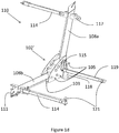
- FIG. 1e illustrating a side view of the assembled connecting bracket and two poles shown in Figure 1d for a clearer view of the basic unit 110.
- the poles 108a and 108b are optionally and preferably further provided relatively close to their free end that is distal from the connecting bracket 102' with a recess 130 in the pole and optionally two holes 132.
- Two holes 132 and recess 130 are adapted to accommodate a wheel 134 that is connected to pole 108b that is adjacent to the ground.
- the wheel 134 is the point that touches the ground onto which the barrier stands so as to be able to easily and promptly move the barrier from one place to another.
- wheel 134 is a collapse spring loaded wheel 136 that is attached through corresponding bores 138 to the holes 132 of pole 108b.
- the wheel 134 is provided with a loaded spring 140 that is configured to collapse once a vehicle hits the barrier and starts to drag it.
- Wheel 134 is adapted to assist in moving the barrier as will be explained herein after and collapses in order to increase the friction of the pole with the ground in case of need.
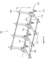
- the barrier as disclosed herein is a modular barrier that can be made of number of basic units or structures as needed according to the width of the road, area, or an opening that need to be blocked.
- the modular barrier 200 is built out of an amount of basic structures or units 202 that is adequate to the length of the barrier that is needed.
- Each of basic units 201 of the assembled modular barrier 200 is made of the building blocks as shown herein before, and particularly, a plurality of connectors 202 to which a plurality of poles 204a and 204b are connected. Poles 204a are connected while directed upwardly and poles 204b are directed to be substantially parallel to the ground.
- the poles 204a and 204b are identical or very similar so as to facilitate their assembly.
- the rotating bars 206a and 206b are opened to a position in which they are perpendicular to the corresponding poles 204a and 204b, respectively.
- the bars 206a and 206b are rotated about a flange 208 to which they are pivotally connected.
- the free end of the rotating bar is designed so it can be secured into the flange 210 of an adjacent pole that is also free to receive and be connected to the bar.
- bars 211 are connected between one connector 202 to the other.
- Parallel bars 206a, 206b, and 211 are only one preferred embodiment with possible connectivity of the units one to the other. Other possibilities of connecting the units is possible as well.
- the poles that are on the ground are preferably provided with a wheel 234 facing to the ground and rests on it as described herein before.
- Barrier 300 comprises several basic units 302, each comprises a connector 304 to which two poles 306a and 306b are connected similarly to as described herein before.
- X type connection 308 is provided to the poles 306a and 306b.
- Pole 306a is provided with two flanges 310 configures to be connected to the X type connection 308 on one side of the X connection, connected in its two free ends while two opposite flanges 312 are configured to be connected to the other side of the X connection 308.
- Pole 306b is also provided with the same connection to the adjacent pole. Both connections are connected to flanges 312 using an R-pin 314 that is easily connecting the X-type connection to the flanges.
- Assembled barrier 400 is made of a plurality of basic units 402, each comprises a connecting bracket 404 to which two poles 406a and 406b are connected. Poles 406a are directed upwardly and poles 406a are parallel to the ground. Poles 406a and 406b are provided with connecting bars 407 and connecting bracket 102 are provided with connecting bars 408 similarly to the connecting bars illustrated in the embodiment shown in Figure 2 .
- additional rods 410 are provided and configures to be arranged in an X arrangement between the opposite and facing each other flanges that connect connecting bars 407 and connecting bars 408 of adjacent poles or connecting brackets, respectively.
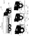
- FIG. 5 showing a heavy vehicle stops at a barrier in accordance with some other exemplary embodiments of the disclosed subject matter, and the situation when the vehicle runs over the barrier.
- the vehicle 500 that drove in a direction indicated by an arrow 501 stops with its bumper at the barrier 502 while the wheels of the vehicle are slightly going over the free end of the pole that is placed on the ground.
- ground refers to sandy, rocky, rough terrain, gravel, asphalt road, a combination thereof and the like.
- the preferred profile of the pole is rhombus that is placed on the ground within the pocket of the connecting bracket with the pointed side upright.
- the arrows 510a, b, and c illustrate the direction of the vehicle that drives forwards towards the barrier 502 in velocities of V0, VI, and V2 wherein the velocities of the vehicle is represented by the length of the arrows that are getting shorter as the vehicle proceeds towards and over the barrier.
- the corresponding velocities V0, V1, and V3 of the vehicle gets lower as the vehicle proceeds.
- the left-hand side illustration shows that the vehicle is in the relatively high velocity V0 represented by a length of the arrow 510a when the vehicle's bumper hits the barrier.
- the stability of the vehicle 500 is deteriorated due to its climb on the sharp edge of the pole 504 and possibly due to damage inflicted on the vehicle's tire by spikes (111 in Figure 1d , as an example) provided to the pole free end.
- the velocity V1 of the vehicle is blocked markedly as represented by arrow 510b.
- the barrier will turn over the thrusting point 508 that forms due to pointing element such as pointing element 118 shown in Figure 1d that can be imbedded into the ground.
- the pole 504 that is adjacent to the ground is raised while the other pole 506 is being lowered and rotated about the thrusting point 508.
- the vehicle's front wheels will be trapped as shown in the illustration while the velocity V2 of the vehicle is further reduced as represented in arrow 510c.
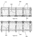
- FIGS 6 a and b illustrating frontal and upper views, respectively, of the barrier shown in Figures 1a and 1b provided with barrier against human crowd, in accordance with some exemplary embodiments of the disclosed subject matter.
- the barrier disclosed in this document can be used for vehicles, however, may be converted into a barrier against crowd and especially human crowd.
- a metallic screen is provided so as to block the crowd.
- Barrier 600 that is similar to the barrier shown in Figure 2 comprises a connector 602 and two poles 604 forming substantially an L shape barrier.
- the poles 604 are firmly connected to the connector 602.
- the bars 606 are opened and connecting the adjacent poles of the modular units of the barrier.
- two screens preferably metallic screens, are placed over the portions of the barrier.
- Screen 608 is placed and connected to the poles of the barrier that are parallel to the ground and screen 610 is placed and connected to the upright poles of the barrier 600. In this way, when crowd of people are going forward towards the barrier and step on screen 608, the barrier will not overturned due to the weight of the people that is placed on the bottom screen, however, the upright screen will not let them proceed.
- the screens that can be made of two parts (the horizontal and the vertical portion) or made of a single portion that has an axis in its middle so as to be placed and fixed to the substantially L-shaped barrier.
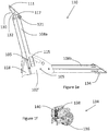
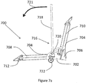
- barrier 700 comprises a connecting bracket 702 provided with two pockets 704 and a pointing element 706.
- the barrier 700 further comprises two poles 708 and 710, while pole 708 is provided with at least one wheel 712 and therefore, this pole is inserted within the connecting bracket so that it is placed substantially parallel to the ground while the wheel 712 touches the ground.
- the other pole 710 can be inserted to within the pocket 704 in the connecting bracket that is directed to the vertical position relative to the ground, in an upright position.
- the other pole 710 doesn't have to be provided with wheels, however, it may be.
- the portions or the rotating bars that connect between the modular units are not shown in Figure 7a , however, can be clearly seen in Figure 7b .
- Barrier 700 is provided with a jack 716 capable of uploading the barrier 700 onto wheels 722 so as to carry the barrier from one point to the other for placement adjustments.
- FIG. 7b illustrating isometric view of the barrier capable of moving in substantially rotating movement from one position to the other using a jack in accordance with an exemplary embodiment of the disclosed subject matter.
- Barrier 700 is shown to be assembled so as to block vehicles. There are many cases in which it is desirable to move the barrier for a limited time so as to open the blockage, as an example, or to adjust it in another positioning. In those cases, the wheels 712 in the bottom portion of the poles 708 become important and useful. In order to activate them, the thrust between the pointing elements 706 and the ground should be eliminated. This is performed using the jack 716.
- Jack 716 comprises a lever 718 and shaft 719 that pass through dedicated and corresponding holes 319 shown in Figure 3a , as an example, in the connecting bracket 302 or 702.
- the lever 718 is connected to shaft 719 by a pin 720.
- Lever 718 is adapted to be moved by the user in a downward movement shown by arrow 721 in order to deactivate its operation and vice versa in order to activate it and allow the barrier to move.
- the free end of lever 718 can be grasped by the hand of the user while this movement correspondingly rotates the connected shaft 719 about its longitudinal axis.
- Shaft 719, which passes through the connecting brackets 702 is provided with a plurality of driving wheels 722.
- the driving wheels are arranged so as a single driving wheel is provided between each basic unit of the modular barrier 700.
- Figures 7a and 7b show a positioning of the jack 716 in which the lever 718 is upwardly positioned and placed so that the driving wheels 722 are in lower positioning in which it is active, touching the ground, and raise the pointing element 706 above the ground so as to allow the barrier 700 with the ability to move using wheels 712 and 722.
- the friction of the heavy metals with the ground is almost eliminated and the barrier 700 can be easily moved without having to use many working hands or machinery.
- FIG. 8a and 8b illustrating an isometric view of a basic unit in accordance with yet another exemplary embodiment of the disclosed subject matter.
- Basic unit 800 is shown to be assembled.
- the basic unit 800 comprises a bracket 801 having three pockets as will be explained.
- a pole 802 is inserted into a pocket 804 in an upright position while two other poles 806a and 806b, which are inserted to within pocket 808a and 808b, respectively, are parallel to the ground.
- the bracket 801 has three pockets, one directed upwardly so that the pole is in an upright position and two pockets that are substantially positioned laterally to the upright pole and are positioned so that they are on the same surface connected by a middle fastener 810, wherein the pockets 808a and 808b are directed to the same plane with an angle of 20-90 degrees between them.
- the bracket in this architecture is steadily placed on the ground so as to provide a steady barrier as will be shown in the following figure.
- connection of the poles 802, 806a, and 806b to the bracket 801 is performed using pins that are designed to rapidly allow the users to assemble the basic units.
- pins that are designed to rapidly allow the users to assemble the basic units.
- two passthrough pins 812 are provided to connect each pole to the bracket.
- the poles as well as the connecting bracket are provided with corresponding bores through which the pins are inserted.
- the pins are solid bars, preferably made of alloy steel having corresponding strength and is characterized by its good fatigue resistance. It should be mentioned that any type of rivet, screw or any other similar connecting element can be inserted through the bores (concealed in Figures 8a and 8b by the pins) so as to withhold the end of the pole within the pocket of the bracket.
- the bracket is designed so as to establish a predetermined angle between the upright poles and the lateral poles while this angle should preferably be about 110 0 ⁇ 10 0.
- Poles 802 as well as 806a and 806b are provided at their free end with spikes 814 that are laser cut sheets of metallic material such as steel. Spikes 814 are designed to inflict additional damage to the vehicle that hits the barrier.
- Each pole 802 as well as 806a and 806b is provided with flanges 816 adapted to maintain a connection to an adjacent pole of another unit.
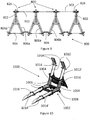
- FIG. 9 illustrating a barrier 900 made of units 800 similar to the units shown in Figures 8a and 8b .
- connecting bars 902 are connected between upwardly positioned poles 802 while their ends are connected to flanges 816 that are provided in the vicinity of the free ends of the poles, as shown previously.
- the connecting bars 902 should be in such a length that the lateral poles 806a or 806b are kept apart from such lateral poles of an adjacent unit.
- poles 806a and 806b are connected to each other by a connecting bar 904 that fastens the structure.
- adjacent lateral poles should also be connected to each other. Therefore, pole 806a that is adjacent to pole 806b of another unit 800 is connected to pole 806b using a rod 904 so that the lower portion of the barrier 900 is steady as the upper portion.
- Rod 904 can be a rod or a chain or any other connecting means that can steadily support the connection between the adjacent units 800 that establish the barrier 900. This applied for all embodiments shown in this disclosure and its variations.
- Unit 1000 comprises a bracket 1002 made of two substantially L shaped tubes 1004 connected to each other by at least one, and preferably three connecting chunks 1006, which are connected in three strategic places (upper, lower, and in the bent) to the L shaped tubes 1004, that render extreme strength to the bracket 1002.
- the chunks can be in an X orientation between the two tubes.
- the angle between the lateral tubes that are placed substantially parallel to the ground and the upwardly directed tubes should preferably be more than 60°.
- a pointing element 1008 as well as an additional pointing heel 1010 are provided to the bracket 1002 so as to render additional strength and stability in case a vehicle is bumping into the basic unit 1000.
- the additional pointing heel 1010 provides among other benefits, a thrusting point that in some cases is effective enough even to turn the vehicle upside down.
- Basic unit 1000 is further comprising poles that are adapted to be inserted into the openings in the L shaped tubes 1004.
- the openings of the tubes function as pockets for the poles.
- Two poles 1012 are inserted in an upright position through the upper openings 1012' of the tube and two poles 1014 are inserted in a horizontal position (lateral) through the lower openings 1014'.
- the two types of poles - the upwardly directed poles and the laterally directed poles - are different in their structure and shape.
- the laterally directed poles 1014 are similar to the poles shown herein before however, the upwardly directed poles 1012 have two portions. The portion that is close to the bracket and is inserted to within the openings 1012' are provided with the same profile as the other poles while the upper portion of the pole is bent and flattened to establish a pointer 1018 that is directed to the direction from which the vehicle is to be stopped. This feature may inflict additional damage to the vehicle that bumps into the barrier.
- Flanges 1016 are provided to the poles so as to connect several units 1000 together in a line so that a barrier 1100 is established. Other flanges can be provided as well.
- the connection can be performed using any type of connection that was disclosed herein before or any other possible connection.
- spikes can be added to the basic unit in order to puncture the tires of the coming vehicle.
- FIG 11 illustrating an isometric view of a barrier made of units similar to the units shown in Figures 10 .
- Barrier 1100 is shown in Figure 11 while the basic units 1000 are not connected to each other. Since the basic units are so firm, each one of them can establish a barrier by itself. However, although it is not shown in the figure, the units can be connected together using methods that were disclosed herein above or other connecting methods.
- poles and the brackets used in order to build the barrier according to the present subject matter are made of very strong materials as mentioned herein before, however, the poles, as an example, can be enforced with internal means such as I beam that can be incorporated within the pole. Other methods of enforcement can be employed themselves.
Landscapes
- Engineering & Computer Science (AREA)
- Architecture (AREA)
- Civil Engineering (AREA)
- Structural Engineering (AREA)
- Refuge Islands, Traffic Blockers, Or Guard Fence (AREA)
- Bridges Or Land Bridges (AREA)
- Toys (AREA)
- Cultivation Receptacles Or Flower-Pots, Or Pots For Seedlings (AREA)
- Pivots And Pivotal Connections (AREA)
- Road Paving Structures (AREA)
Claims (3)
- Bauelement (100), welches dazu eingerichtet ist, mit anderen Bauelementen ausgerichtet zu werden, um eine modulare Barriere (200) aufzubauen, welche dazu eingerichtet ist, Fahrzeuge, die sich auf einem Untergrund bewegen, zu stoppen, wobei das Bauelement (100) umfasst:einen Verbinder (102), welcher zwei Aufnahmetaschen umfasst, wobei eine der Aufnahmetaschen (106) seitwärts ausgerichtet ist und eine der Aufnahmetaschen (106) in einem vorbestimmten Winkel von mehr als 90° relativ zu der seitwärts ausgerichteten Aufnahmetasche ausgerichtet ist, wobei der Verbinder mit einem Vorsprungelement (118) ausgebildet ist, welches einen Kraftpunkt bereitstellt;zwei Stangen, wobei eine der Stangen (108b) dazu eingerichtet ist, innerhalb der einen der beiden Aufnahmetaschen, welche seitwärts ausgerichtet ist, aufgenommen zu werden, sodass die Stange im Wesentlichen parallel zu dem Untergrund ausgerichtet ist, und wobei die andere der Stangen (108a) dazu eingerichtet ist, innerhalb der anderen der beiden Aufnahmetaschen, welche in dem vorbestimmten Winkel ausgerichtet ist, aufgenommen zu werden, um es der modularen Barriere zu ermöglichen, die Fahrzeuge zu stoppen; undeinen Rotierstab (114), welcher mittels eines Kopplers mit einer der Stangen verbunden ist, wobei der Rotierstab dazu eingerichtet ist, die Stange mit einer Stange eines benachbarten Bauelements zu verbinden.
- Bauelement gemäß Anspruch 1, wobei der Rotierstab dazu eingerichtet ist, zwischen einem Ruhezustand, in welchem der Rotierstab zu der Stange benachbart ist, und einem aktiven Zustand, in welchem der Rotierstab von der Stange weggedreht und im Wesentlichen senkrecht zu der Stange ausgerichtet ist, gedreht zu werden.
- Modulare Barriere, welche mehrere Bauelemente gemäß einem der vorangehenden Ansprüche umfasst, wobei benachbarte Bauelemente miteinander verbunden sind.
Priority Applications (3)
| Application Number | Priority Date | Filing Date | Title |
|---|---|---|---|
| PL17202269T PL3323942T3 (pl) | 2016-11-17 | 2017-11-17 | Łatwa w transporcie i montażu modułowa bariera |
| SI201731121T SI3323942T1 (sl) | 2016-11-17 | 2017-11-17 | Modularna zapora, preprosta za transport in sestavljanje |
| HRP20220448TT HRP20220448T1 (hr) | 2016-11-17 | 2017-11-17 | Lako prenosiva i modularna barijera |
Applications Claiming Priority (1)
| Application Number | Priority Date | Filing Date | Title |
|---|---|---|---|
| US201662423220P | 2016-11-17 | 2016-11-17 |
Publications (2)
| Publication Number | Publication Date |
|---|---|
| EP3323942A1 EP3323942A1 (de) | 2018-05-23 |
| EP3323942B1 true EP3323942B1 (de) | 2022-01-05 |
Family
ID=60387898
Family Applications (1)
| Application Number | Title | Priority Date | Filing Date |
|---|---|---|---|
| EP17202269.1A Active EP3323942B1 (de) | 2016-11-17 | 2017-11-17 | Modulare barriere leicht zu transportieren und zusammenzusetzen |
Country Status (13)
| Country | Link |
|---|---|
| US (1) | US11572666B2 (de) |
| EP (1) | EP3323942B1 (de) |
| CY (1) | CY1125091T1 (de) |
| DE (1) | DE202017006953U1 (de) |
| ES (1) | ES2909809T3 (de) |
| HR (1) | HRP20220448T1 (de) |
| HU (1) | HUE058118T2 (de) |
| IL (1) | IL266646B2 (de) |
| LT (1) | LT3323942T (de) |
| PL (1) | PL3323942T3 (de) |
| PT (1) | PT3323942T (de) |
| SI (1) | SI3323942T1 (de) |
| WO (1) | WO2018092134A1 (de) |
Families Citing this family (20)
| Publication number | Priority date | Publication date | Assignee | Title |
|---|---|---|---|---|
| BE1025071B1 (fr) * | 2017-03-21 | 2018-10-24 | Pitagone Sa | Dispositif de protection contre les attaques de camion-béliers |
| DK3655589T3 (da) * | 2017-07-18 | 2026-01-26 | Amos Klein | Rullebarrieresystem |
| ES2834458T3 (es) * | 2017-11-20 | 2021-06-17 | Amos Klein | Unidad básica de barrera erigible y una barrera erigible que comprende la misma |
| DE202018103084U1 (de) * | 2018-06-01 | 2018-09-04 | Christian Barz | Mobile Straßensperre |
| FR3084379B1 (fr) * | 2018-07-25 | 2020-07-10 | Alain Antoniazzi | Obstacle pour stopper un vehicule |
| US11225763B2 (en) * | 2018-08-03 | 2022-01-18 | City of Benicia | Device for thwarting vehicular stunts |
| JP6741265B1 (ja) * | 2018-10-17 | 2020-08-19 | 株式会社白石ゴム製作所 | 車両規制装置および車両規制装置の設置方法 |
| WO2020144612A1 (en) | 2019-01-09 | 2020-07-16 | Klein Amos | Collapsible barrier and a system comprising the same |
| EP3690142A1 (de) * | 2019-01-30 | 2020-08-05 | Pitagone | Vorrichtung zum schutz vor lkw rammattacken |
| IT201900002589A1 (it) * | 2019-02-22 | 2020-08-22 | Good Job S R L | Sistema modulare di barriere stradali |
| WO2020174445A1 (en) | 2019-02-28 | 2020-09-03 | Klein Amos | Dissecting barrier |
| NL2022924B1 (en) | 2019-04-11 | 2020-10-20 | Laura Metaal Holding B V | Friction-increasing element for attachment to a roadblock, and roadblock provided with at least one such friction-increasing element |
| WO2020222156A1 (en) | 2019-04-30 | 2020-11-05 | Klein Amos | Telescopic jersey barrier |
| US12553200B2 (en) * | 2019-07-29 | 2026-02-17 | Peter Duncan WHITFORD | Vehicle mitigation systems and methods of deploying a vehicle mitigation system |
| FR3115546B1 (fr) * | 2020-10-22 | 2023-11-17 | Bouix Pierre Simon | Barrière de sécurité anti voiture bélier |
| US20220170219A1 (en) * | 2020-12-02 | 2022-06-02 | Jonathan Jonny Melic | Wheel stop bracket and system for wheeled machinery |
| US20220298733A1 (en) * | 2021-03-22 | 2022-09-22 | John Graziadei | Anti-Ram Barrier |
| AU2023275395B2 (en) * | 2022-04-28 | 2026-01-29 | Peter Duncan WHITFORD | Vehicle mitigation system |
| FR3138454B1 (fr) * | 2022-07-28 | 2024-06-28 | Klozmann | Dispositif de barrière anti-véhicule bélier pour véhicule de 7,2t, voire 25t |
| FR3145574B1 (fr) * | 2023-02-07 | 2025-05-02 | Klozmann | Dispositif de barrière anti-véhicule bélier pour véhicule de 7,2T, voire 25T |
Citations (1)
| Publication number | Priority date | Publication date | Assignee | Title |
|---|---|---|---|---|
| EP3378992A1 (de) * | 2017-03-21 | 2018-09-26 | Pitagone | Schutzvorrichtung gegen rammangriffe von lastkraftwagen |
Family Cites Families (25)
| Publication number | Priority date | Publication date | Assignee | Title |
|---|---|---|---|---|
| US3057601A (en) * | 1959-07-13 | 1962-10-09 | Simpson De Roy | Portable highway barricade |
| GB2178094B (en) * | 1985-06-10 | 1988-04-20 | Glenfrome Engineering Limited | Portable barrier |
| US5188342A (en) * | 1992-01-15 | 1993-02-23 | Sinco Incorporated | Portable safety rail system |
| GB0122128D0 (en) * | 2001-09-13 | 2001-10-31 | Kee Klamp Ltd | A connector for a modular safety rail |
| US6702512B1 (en) * | 2003-01-27 | 2004-03-09 | George S. Reale | Vehicle arresting installation |
| JP4461330B2 (ja) * | 2004-11-05 | 2010-05-12 | 株式会社花井製作所 | 車両強制停止装置と該装置を使用した車両強制停止方法 |
| WO2009029301A2 (en) * | 2007-05-08 | 2009-03-05 | Whitford Peter D | Portable perimeter defense system |
| US8215866B2 (en) * | 2007-05-08 | 2012-07-10 | Whitford Peter D | Portable perimeter defense barrier and system |
| KR20100010544U (ko) * | 2009-04-17 | 2010-10-27 | (주)런기획 | 간이 펜스 |
| US20120177439A1 (en) | 2011-01-11 | 2012-07-12 | More Uzi | Portable Vehicle Barrier |
| SI3186445T1 (sl) | 2014-08-26 | 2020-07-31 | KLEIN, Amos | Gibljiva modularna ovira za vozila |
| EP3445914B1 (de) * | 2016-04-20 | 2020-05-20 | Guardiar Europe BVBA | Tor und sicherheitssperre mit einem tor |
| CN107227705A (zh) * | 2016-07-18 | 2017-10-03 | 潘学德 | 一种便携式阻车模块及阻车器 |
| CN106351146B (zh) * | 2016-09-14 | 2018-10-23 | 天津工业大学 | 一种便携式碳纤维混杂复合材料阻车路障及其应用 |
| US10415198B1 (en) * | 2017-01-27 | 2019-09-17 | Cowboy Barriers Llc | Mobile vehicle barrier |
| CN106996087A (zh) * | 2017-06-02 | 2017-08-01 | 宁波力度警用装备科技有限公司 | 一种阻车器 |
| DK3655589T3 (da) * | 2017-07-18 | 2026-01-26 | Amos Klein | Rullebarrieresystem |
| US10370808B2 (en) * | 2017-08-17 | 2019-08-06 | Neusch Innovations, Lp | Modular vehicle barrier |
| FR3071856B1 (fr) * | 2017-10-04 | 2019-10-11 | Jean Louis Pavanello | Barriere anti voiture belier |
| ES2834458T3 (es) * | 2017-11-20 | 2021-06-17 | Amos Klein | Unidad básica de barrera erigible y una barrera erigible que comprende la misma |
| DE202018103084U1 (de) * | 2018-06-01 | 2018-09-04 | Christian Barz | Mobile Straßensperre |
| FR3082532A1 (fr) * | 2018-06-19 | 2019-12-20 | Ase | Barriere anti-vehicule belier btp8 |
| FR3084379B1 (fr) * | 2018-07-25 | 2020-07-10 | Alain Antoniazzi | Obstacle pour stopper un vehicule |
| GB2596455B (en) * | 2019-02-20 | 2023-05-24 | Rologard Global Company Llc | Portable vehicle barrier |
| US11365955B2 (en) * | 2019-05-22 | 2022-06-21 | Event Crowd Control Inc. | Apparatus for hindering vehicular movement |
-
2017
- 2017-11-16 US US16/461,620 patent/US11572666B2/en active Active
- 2017-11-16 IL IL266646A patent/IL266646B2/en unknown
- 2017-11-16 WO PCT/IL2017/051250 patent/WO2018092134A1/en not_active Ceased
- 2017-11-17 EP EP17202269.1A patent/EP3323942B1/de active Active
- 2017-11-17 ES ES17202269T patent/ES2909809T3/es active Active
- 2017-11-17 HU HUE17202269A patent/HUE058118T2/hu unknown
- 2017-11-17 LT LTEP17202269.1T patent/LT3323942T/lt unknown
- 2017-11-17 HR HRP20220448TT patent/HRP20220448T1/hr unknown
- 2017-11-17 PL PL17202269T patent/PL3323942T3/pl unknown
- 2017-11-17 SI SI201731121T patent/SI3323942T1/sl unknown
- 2017-11-17 DE DE202017006953.9U patent/DE202017006953U1/de not_active Expired - Lifetime
- 2017-11-17 PT PT172022691T patent/PT3323942T/pt unknown
-
2022
- 2022-03-30 CY CY20221100246T patent/CY1125091T1/el unknown
Patent Citations (1)
| Publication number | Priority date | Publication date | Assignee | Title |
|---|---|---|---|---|
| EP3378992A1 (de) * | 2017-03-21 | 2018-09-26 | Pitagone | Schutzvorrichtung gegen rammangriffe von lastkraftwagen |
Also Published As
| Publication number | Publication date |
|---|---|
| SI3323942T1 (sl) | 2022-05-31 |
| LT3323942T (lt) | 2022-04-25 |
| CY1125091T1 (el) | 2024-02-16 |
| IL266646B1 (en) | 2024-12-01 |
| WO2018092134A1 (en) | 2018-05-24 |
| IL266646A (en) | 2019-07-31 |
| US11572666B2 (en) | 2023-02-07 |
| IL266646B2 (en) | 2025-04-01 |
| DE202017006953U1 (de) | 2019-03-19 |
| HUE058118T2 (hu) | 2022-07-28 |
| EP3323942A1 (de) | 2018-05-23 |
| PL3323942T3 (pl) | 2022-04-25 |
| HRP20220448T1 (hr) | 2022-05-27 |
| ES2909809T3 (es) | 2022-05-10 |
| PT3323942T (pt) | 2022-04-13 |
| US20200063387A1 (en) | 2020-02-27 |
Similar Documents
| Publication | Publication Date | Title |
|---|---|---|
| EP3323942B1 (de) | Modulare barriere leicht zu transportieren und zusammenzusetzen | |
| US8215866B2 (en) | Portable perimeter defense barrier and system | |
| EP3486373B1 (de) | Basiseinheit für aufrichtbare barriere und aufrichtbare barriere damit | |
| US7918622B2 (en) | Portable perimeter defense system | |
| US8528915B2 (en) | Rider platform for self-propelled vehicle | |
| US4961471A (en) | Post hole digger | |
| EP3655589A1 (de) | Rollbarrieresystem | |
| DE202008013393U1 (de) | Baumaschine, insbesondere Straßenbaumaschine oder Tagebaumaschine | |
| WO2008102080A1 (fr) | Dispositif modulable automatique qui forme une structure haute a l'arriere d'un vehicule automobile ou qui se compacte derriere les sieges avants | |
| KR20170015282A (ko) | 프레임워크 구조 | |
| US12416124B2 (en) | Dissecting barrier | |
| US20090008047A1 (en) | Stump Grinding Debris Containment Structure | |
| EP2708653A1 (de) | Mobiles Barrierensystem | |
| US4467876A (en) | Ripper tooth means | |
| EP3918132B1 (de) | Rammschutz gegen lkws | |
| JP2004225492A (ja) | 落石防護網用アンカー | |
| EP1937052B1 (de) | Landwirtschaftliche maschine mit einem mittelteil und auf jeder seite davon klappbaren auslegern | |
| CN114837197B (zh) | 一种具有测量基坑施工参数的基坑支护结构 | |
| JP2516727B2 (ja) | 移動式杭打機 | |
| EP4660375A1 (de) | Faltbare tragbare barrieren | |
| AU2012216650A1 (en) | Wheelbarrow | |
| WO2024019622A1 (en) | A mobile or movable barrier | |
| NO20220815A1 (en) | A mobile or movable barrier | |
| AU2004100807A4 (en) | Vehicle display ramps | |
| JP2527909Y2 (ja) | カルチベ−タ−におけるフレ−ムの折りたたみ装置 |
Legal Events
| Date | Code | Title | Description |
|---|---|---|---|
| REG | Reference to a national code |
Ref country code: HR Ref legal event code: TUEP Ref document number: P20220448 Country of ref document: HR Ref country code: DE Ref legal event code: R138 Ref document number: 202017006953 Country of ref document: DE Free format text: GERMAN DOCUMENT NUMBER IS 602017051825 |
|
| PUAI | Public reference made under article 153(3) epc to a published international application that has entered the european phase |
Free format text: ORIGINAL CODE: 0009012 |
|
| STAA | Information on the status of an ep patent application or granted ep patent |
Free format text: STATUS: THE APPLICATION HAS BEEN PUBLISHED |
|
| AK | Designated contracting states |
Kind code of ref document: A1 Designated state(s): AL AT BE BG CH CY CZ DE DK EE ES FI FR GB GR HR HU IE IS IT LI LT LU LV MC MK MT NL NO PL PT RO RS SE SI SK SM TR |
|
| AX | Request for extension of the european patent |
Extension state: BA ME |
|
| STAA | Information on the status of an ep patent application or granted ep patent |
Free format text: STATUS: REQUEST FOR EXAMINATION WAS MADE |
|
| 17P | Request for examination filed |
Effective date: 20181123 |
|
| RBV | Designated contracting states (corrected) |
Designated state(s): AL AT BE BG CH CY CZ DE DK EE ES FI FR GB GR HR HU IE IS IT LI LT LU LV MC MK MT NL NO PL PT RO RS SE SI SK SM TR |
|
| STAA | Information on the status of an ep patent application or granted ep patent |
Free format text: STATUS: EXAMINATION IS IN PROGRESS |
|
| 17Q | First examination report despatched |
Effective date: 20190214 |
|
| GRAP | Despatch of communication of intention to grant a patent |
Free format text: ORIGINAL CODE: EPIDOSNIGR1 |
|
| STAA | Information on the status of an ep patent application or granted ep patent |
Free format text: STATUS: GRANT OF PATENT IS INTENDED |
|
| INTG | Intention to grant announced |
Effective date: 20210219 |
|
| GRAJ | Information related to disapproval of communication of intention to grant by the applicant or resumption of examination proceedings by the epo deleted |
Free format text: ORIGINAL CODE: EPIDOSDIGR1 |
|
| STAA | Information on the status of an ep patent application or granted ep patent |
Free format text: STATUS: EXAMINATION IS IN PROGRESS |
|
| GRAP | Despatch of communication of intention to grant a patent |
Free format text: ORIGINAL CODE: EPIDOSNIGR1 |
|
| STAA | Information on the status of an ep patent application or granted ep patent |
Free format text: STATUS: GRANT OF PATENT IS INTENDED |
|
| INTC | Intention to grant announced (deleted) | ||
| INTG | Intention to grant announced |
Effective date: 20210715 |
|
| GRAS | Grant fee paid |
Free format text: ORIGINAL CODE: EPIDOSNIGR3 |
|
| GRAA | (expected) grant |
Free format text: ORIGINAL CODE: 0009210 |
|
| STAA | Information on the status of an ep patent application or granted ep patent |
Free format text: STATUS: THE PATENT HAS BEEN GRANTED |
|
| AK | Designated contracting states |
Kind code of ref document: B1 Designated state(s): AL AT BE BG CH CY CZ DE DK EE ES FI FR GB GR HR HU IE IS IT LI LT LU LV MC MK MT NL NO PL PT RO RS SE SI SK SM TR |
|
| REG | Reference to a national code |
Ref country code: GB Ref legal event code: FG4D |
|
| REG | Reference to a national code |
Ref country code: CH Ref legal event code: EP |
|
| REG | Reference to a national code |
Ref country code: AT Ref legal event code: REF Ref document number: 1460722 Country of ref document: AT Kind code of ref document: T Effective date: 20220115 |
|
| REG | Reference to a national code |
Ref country code: DE Ref legal event code: R096 Ref document number: 602017051825 Country of ref document: DE |
|
| REG | Reference to a national code |
Ref country code: IE Ref legal event code: FG4D |
|
| REG | Reference to a national code |
Ref country code: RO Ref legal event code: EPE |
|
| REG | Reference to a national code |
Ref country code: PT Ref legal event code: SC4A Ref document number: 3323942 Country of ref document: PT Date of ref document: 20220413 Kind code of ref document: T Free format text: AVAILABILITY OF NATIONAL TRANSLATION Effective date: 20220404 |
|
| REG | Reference to a national code |
Ref country code: NL Ref legal event code: FP |
|
| REG | Reference to a national code |
Ref country code: SE Ref legal event code: TRGR |
|
| REG | Reference to a national code |
Ref country code: ES Ref legal event code: FG2A Ref document number: 2909809 Country of ref document: ES Kind code of ref document: T3 Effective date: 20220510 |
|
| REG | Reference to a national code |
Ref country code: HR Ref legal event code: T1PR Ref document number: P20220448 Country of ref document: HR |
|
| REG | Reference to a national code |
Ref country code: GR Ref legal event code: EP Ref document number: 20220400760 Country of ref document: GR Effective date: 20220509 |
|
| REG | Reference to a national code |
Ref country code: NO Ref legal event code: T2 Effective date: 20220105 |
|
| REG | Reference to a national code |
Ref country code: AT Ref legal event code: MK05 Ref document number: 1460722 Country of ref document: AT Kind code of ref document: T Effective date: 20220105 |
|
| REG | Reference to a national code |
Ref country code: HU Ref legal event code: AG4A Ref document number: E058118 Country of ref document: HU |
|
| PG25 | Lapsed in a contracting state [announced via postgrant information from national office to epo] |
Ref country code: RS Free format text: LAPSE BECAUSE OF FAILURE TO SUBMIT A TRANSLATION OF THE DESCRIPTION OR TO PAY THE FEE WITHIN THE PRESCRIBED TIME-LIMIT Effective date: 20220105 |
|
| PG25 | Lapsed in a contracting state [announced via postgrant information from national office to epo] |
Ref country code: FI Free format text: LAPSE BECAUSE OF FAILURE TO SUBMIT A TRANSLATION OF THE DESCRIPTION OR TO PAY THE FEE WITHIN THE PRESCRIBED TIME-LIMIT Effective date: 20220105 Ref country code: AT Free format text: LAPSE BECAUSE OF FAILURE TO SUBMIT A TRANSLATION OF THE DESCRIPTION OR TO PAY THE FEE WITHIN THE PRESCRIBED TIME-LIMIT Effective date: 20220105 |
|
| REG | Reference to a national code |
Ref country code: DE Ref legal event code: R097 Ref document number: 602017051825 Country of ref document: DE |
|
| PG25 | Lapsed in a contracting state [announced via postgrant information from national office to epo] |
Ref country code: SM Free format text: LAPSE BECAUSE OF FAILURE TO SUBMIT A TRANSLATION OF THE DESCRIPTION OR TO PAY THE FEE WITHIN THE PRESCRIBED TIME-LIMIT Effective date: 20220105 Ref country code: EE Free format text: LAPSE BECAUSE OF FAILURE TO SUBMIT A TRANSLATION OF THE DESCRIPTION OR TO PAY THE FEE WITHIN THE PRESCRIBED TIME-LIMIT Effective date: 20220105 Ref country code: DK Free format text: LAPSE BECAUSE OF FAILURE TO SUBMIT A TRANSLATION OF THE DESCRIPTION OR TO PAY THE FEE WITHIN THE PRESCRIBED TIME-LIMIT Effective date: 20220105 |
|
| PLBE | No opposition filed within time limit |
Free format text: ORIGINAL CODE: 0009261 |
|
| STAA | Information on the status of an ep patent application or granted ep patent |
Free format text: STATUS: NO OPPOSITION FILED WITHIN TIME LIMIT |
|
| PG25 | Lapsed in a contracting state [announced via postgrant information from national office to epo] |
Ref country code: AL Free format text: LAPSE BECAUSE OF FAILURE TO SUBMIT A TRANSLATION OF THE DESCRIPTION OR TO PAY THE FEE WITHIN THE PRESCRIBED TIME-LIMIT Effective date: 20220105 |
|
| REG | Reference to a national code |
Ref country code: HR Ref legal event code: ODRP Ref document number: P20220448 Country of ref document: HR Payment date: 20221107 Year of fee payment: 6 |
|
| 26N | No opposition filed |
Effective date: 20221006 |
|
| PGFP | Annual fee paid to national office [announced via postgrant information from national office to epo] |
Ref country code: TR Payment date: 20221107 Year of fee payment: 6 Ref country code: SK Payment date: 20221110 Year of fee payment: 6 Ref country code: SE Payment date: 20221107 Year of fee payment: 6 Ref country code: RO Payment date: 20221107 Year of fee payment: 6 Ref country code: PT Payment date: 20221104 Year of fee payment: 6 Ref country code: NO Payment date: 20221108 Year of fee payment: 6 Ref country code: LT Payment date: 20221111 Year of fee payment: 6 Ref country code: IT Payment date: 20221118 Year of fee payment: 6 Ref country code: IE Payment date: 20221106 Year of fee payment: 6 Ref country code: GB Payment date: 20221107 Year of fee payment: 6 Ref country code: FR Payment date: 20221109 Year of fee payment: 6 Ref country code: DE Payment date: 20221118 Year of fee payment: 6 Ref country code: CZ Payment date: 20221118 Year of fee payment: 6 |
|
| PGFP | Annual fee paid to national office [announced via postgrant information from national office to epo] |
Ref country code: SI Payment date: 20221110 Year of fee payment: 6 Ref country code: PL Payment date: 20221108 Year of fee payment: 6 Ref country code: HU Payment date: 20221106 Year of fee payment: 6 Ref country code: HR Payment date: 20221107 Year of fee payment: 6 Ref country code: GR Payment date: 20221108 Year of fee payment: 6 Ref country code: BE Payment date: 20221109 Year of fee payment: 6 |
|
| PGFP | Annual fee paid to national office [announced via postgrant information from national office to epo] |
Ref country code: MT Payment date: 20221115 Year of fee payment: 6 Ref country code: MK Payment date: 20221104 Year of fee payment: 6 |
|
| PGFP | Annual fee paid to national office [announced via postgrant information from national office to epo] |
Ref country code: CY Payment date: 20221108 Year of fee payment: 6 |
|
| PG25 | Lapsed in a contracting state [announced via postgrant information from national office to epo] |
Ref country code: MC Free format text: LAPSE BECAUSE OF FAILURE TO SUBMIT A TRANSLATION OF THE DESCRIPTION OR TO PAY THE FEE WITHIN THE PRESCRIBED TIME-LIMIT Effective date: 20220105 |
|
| REG | Reference to a national code |
Ref country code: CH Ref legal event code: PL |
|
| REG | Reference to a national code |
Ref country code: NL Ref legal event code: MM Effective date: 20221201 |
|
| PG25 | Lapsed in a contracting state [announced via postgrant information from national office to epo] |
Ref country code: LV Free format text: LAPSE BECAUSE OF NON-PAYMENT OF DUE FEES Effective date: 20221117 Ref country code: LI Free format text: LAPSE BECAUSE OF NON-PAYMENT OF DUE FEES Effective date: 20221130 Ref country code: CH Free format text: LAPSE BECAUSE OF NON-PAYMENT OF DUE FEES Effective date: 20221130 |
|
| PG25 | Lapsed in a contracting state [announced via postgrant information from national office to epo] |
Ref country code: NL Free format text: LAPSE BECAUSE OF NON-PAYMENT OF DUE FEES Effective date: 20221201 Ref country code: LU Free format text: LAPSE BECAUSE OF NON-PAYMENT OF DUE FEES Effective date: 20221117 |
|
| REG | Reference to a national code |
Ref country code: ES Ref legal event code: FD2A Effective date: 20231229 |
|
| PG25 | Lapsed in a contracting state [announced via postgrant information from national office to epo] |
Ref country code: ES Free format text: LAPSE BECAUSE OF NON-PAYMENT OF DUE FEES Effective date: 20221118 |
|
| PG25 | Lapsed in a contracting state [announced via postgrant information from national office to epo] |
Ref country code: ES Free format text: LAPSE BECAUSE OF NON-PAYMENT OF DUE FEES Effective date: 20221118 |
|
| REG | Reference to a national code |
Ref country code: HR Ref legal event code: PBON Ref document number: P20220448 Country of ref document: HR Effective date: 20231117 |
|
| REG | Reference to a national code |
Ref country code: DE Ref legal event code: R119 Ref document number: 602017051825 Country of ref document: DE |
|
| REG | Reference to a national code |
Ref country code: LT Ref legal event code: MM4D Effective date: 20231117 |
|
| REG | Reference to a national code |
Ref country code: SE Ref legal event code: EUG |
|
| PG25 | Lapsed in a contracting state [announced via postgrant information from national office to epo] |
Ref country code: LT Free format text: LAPSE BECAUSE OF NON-PAYMENT OF DUE FEES Effective date: 20231117 |
|
| PG25 | Lapsed in a contracting state [announced via postgrant information from national office to epo] |
Ref country code: GR Free format text: LAPSE BECAUSE OF NON-PAYMENT OF DUE FEES Effective date: 20240610 |
|
| PG25 | Lapsed in a contracting state [announced via postgrant information from national office to epo] |
Ref country code: HR Free format text: LAPSE BECAUSE OF NON-PAYMENT OF DUE FEES Effective date: 20231117 |
|
| PG25 | Lapsed in a contracting state [announced via postgrant information from national office to epo] |
Ref country code: CZ Free format text: LAPSE BECAUSE OF NON-PAYMENT OF DUE FEES Effective date: 20231117 |
|
| GBPC | Gb: european patent ceased through non-payment of renewal fee |
Effective date: 20231117 |
|
| PG25 | Lapsed in a contracting state [announced via postgrant information from national office to epo] |
Ref country code: SK Free format text: LAPSE BECAUSE OF NON-PAYMENT OF DUE FEES Effective date: 20231117 |
|
| PG25 | Lapsed in a contracting state [announced via postgrant information from national office to epo] |
Ref country code: SK Free format text: LAPSE BECAUSE OF NON-PAYMENT OF DUE FEES Effective date: 20231117 Ref country code: RO Free format text: LAPSE BECAUSE OF NON-PAYMENT OF DUE FEES Effective date: 20231117 Ref country code: NO Free format text: LAPSE BECAUSE OF NON-PAYMENT OF DUE FEES Effective date: 20231130 Ref country code: LT Free format text: LAPSE BECAUSE OF NON-PAYMENT OF DUE FEES Effective date: 20231117 Ref country code: HR Free format text: LAPSE BECAUSE OF NON-PAYMENT OF DUE FEES Effective date: 20231117 Ref country code: GR Free format text: LAPSE BECAUSE OF NON-PAYMENT OF DUE FEES Effective date: 20240610 Ref country code: CZ Free format text: LAPSE BECAUSE OF NON-PAYMENT OF DUE FEES Effective date: 20231117 Ref country code: CY Free format text: LAPSE BECAUSE OF NON-PAYMENT OF DUE FEES Effective date: 20231117 Ref country code: BG Free format text: LAPSE BECAUSE OF NON-PAYMENT OF DUE FEES Effective date: 20221117 Ref country code: SI Free format text: LAPSE BECAUSE OF NON-PAYMENT OF DUE FEES Effective date: 20231118 |
|
| PG25 | Lapsed in a contracting state [announced via postgrant information from national office to epo] |
Ref country code: PT Free format text: LAPSE BECAUSE OF NON-PAYMENT OF DUE FEES Effective date: 20240517 |
|
| REG | Reference to a national code |
Ref country code: BE Ref legal event code: MM Effective date: 20231130 |
|
| PG25 | Lapsed in a contracting state [announced via postgrant information from national office to epo] |
Ref country code: SE Free format text: LAPSE BECAUSE OF NON-PAYMENT OF DUE FEES Effective date: 20231118 Ref country code: PT Free format text: LAPSE BECAUSE OF NON-PAYMENT OF DUE FEES Effective date: 20240517 Ref country code: HU Free format text: LAPSE BECAUSE OF NON-PAYMENT OF DUE FEES Effective date: 20231118 |
|
| REG | Reference to a national code |
Ref country code: IE Ref legal event code: MM4A |
|
| REG | Reference to a national code |
Ref country code: SI Ref legal event code: KO00 Effective date: 20240819 |
|
| PG25 | Lapsed in a contracting state [announced via postgrant information from national office to epo] |
Ref country code: IE Free format text: LAPSE BECAUSE OF NON-PAYMENT OF DUE FEES Effective date: 20231117 Ref country code: DE Free format text: LAPSE BECAUSE OF NON-PAYMENT OF DUE FEES Effective date: 20240601 |
|
| PG25 | Lapsed in a contracting state [announced via postgrant information from national office to epo] |
Ref country code: GB Free format text: LAPSE BECAUSE OF NON-PAYMENT OF DUE FEES Effective date: 20231117 |
|
| PG25 | Lapsed in a contracting state [announced via postgrant information from national office to epo] |
Ref country code: BE Free format text: LAPSE BECAUSE OF NON-PAYMENT OF DUE FEES Effective date: 20231130 |
|
| PG25 | Lapsed in a contracting state [announced via postgrant information from national office to epo] |
Ref country code: FR Free format text: LAPSE BECAUSE OF NON-PAYMENT OF DUE FEES Effective date: 20231130 |
|
| PG25 | Lapsed in a contracting state [announced via postgrant information from national office to epo] |
Ref country code: IE Free format text: LAPSE BECAUSE OF NON-PAYMENT OF DUE FEES Effective date: 20231117 Ref country code: GB Free format text: LAPSE BECAUSE OF NON-PAYMENT OF DUE FEES Effective date: 20231117 Ref country code: FR Free format text: LAPSE BECAUSE OF NON-PAYMENT OF DUE FEES Effective date: 20231130 Ref country code: DE Free format text: LAPSE BECAUSE OF NON-PAYMENT OF DUE FEES Effective date: 20240601 Ref country code: BE Free format text: LAPSE BECAUSE OF NON-PAYMENT OF DUE FEES Effective date: 20231130 |
|
| PG25 | Lapsed in a contracting state [announced via postgrant information from national office to epo] |
Ref country code: IT Free format text: LAPSE BECAUSE OF NON-PAYMENT OF DUE FEES Effective date: 20231117 |
|
| PG25 | Lapsed in a contracting state [announced via postgrant information from national office to epo] |
Ref country code: IT Free format text: LAPSE BECAUSE OF NON-PAYMENT OF DUE FEES Effective date: 20231117 |
|
| PG25 | Lapsed in a contracting state [announced via postgrant information from national office to epo] |
Ref country code: PL Free format text: LAPSE BECAUSE OF NON-PAYMENT OF DUE FEES Effective date: 20231117 |
|
| PG25 | Lapsed in a contracting state [announced via postgrant information from national office to epo] |
Ref country code: IS Free format text: LAPSE BECAUSE OF NON-PAYMENT OF DUE FEES Effective date: 20230606 |