EP3322942B1 - Verfahren zum herstellen eines wellrippenelementes, wellrippenelement und heizregister - Google Patents
Verfahren zum herstellen eines wellrippenelementes, wellrippenelement und heizregister Download PDFInfo
- Publication number
- EP3322942B1 EP3322942B1 EP16736878.6A EP16736878A EP3322942B1 EP 3322942 B1 EP3322942 B1 EP 3322942B1 EP 16736878 A EP16736878 A EP 16736878A EP 3322942 B1 EP3322942 B1 EP 3322942B1
- Authority
- EP
- European Patent Office
- Prior art keywords
- corrugated fin
- corrugated
- fin element
- heating
- apexes
- Prior art date
- Legal status (The legal status is an assumption and is not a legal conclusion. Google has not performed a legal analysis and makes no representation as to the accuracy of the status listed.)
- Active
Links
Images


Classifications
-
- B—PERFORMING OPERATIONS; TRANSPORTING
- B21—MECHANICAL METAL-WORKING WITHOUT ESSENTIALLY REMOVING MATERIAL; PUNCHING METAL
- B21D—WORKING OR PROCESSING OF SHEET METAL OR METAL TUBES, RODS OR PROFILES WITHOUT ESSENTIALLY REMOVING MATERIAL; PUNCHING METAL
- B21D53/00—Making other particular articles
- B21D53/02—Making other particular articles heat exchangers or parts thereof, e.g. radiators, condensers fins, headers
- B21D53/022—Making the fins
- B21D53/025—Louvered fins
-
- B—PERFORMING OPERATIONS; TRANSPORTING
- B21—MECHANICAL METAL-WORKING WITHOUT ESSENTIALLY REMOVING MATERIAL; PUNCHING METAL
- B21D—WORKING OR PROCESSING OF SHEET METAL OR METAL TUBES, RODS OR PROFILES WITHOUT ESSENTIALLY REMOVING MATERIAL; PUNCHING METAL
- B21D53/00—Making other particular articles
- B21D53/02—Making other particular articles heat exchangers or parts thereof, e.g. radiators, condensers fins, headers
- B21D53/022—Making the fins
-
- B—PERFORMING OPERATIONS; TRANSPORTING
- B21—MECHANICAL METAL-WORKING WITHOUT ESSENTIALLY REMOVING MATERIAL; PUNCHING METAL
- B21D—WORKING OR PROCESSING OF SHEET METAL OR METAL TUBES, RODS OR PROFILES WITHOUT ESSENTIALLY REMOVING MATERIAL; PUNCHING METAL
- B21D13/00—Corrugating sheet metal, rods or profiles; Bending sheet metal, rods or profiles into wave form
- B21D13/10—Corrugating sheet metal, rods or profiles; Bending sheet metal, rods or profiles into wave form into a peculiar profiling shape
-
- B—PERFORMING OPERATIONS; TRANSPORTING
- B21—MECHANICAL METAL-WORKING WITHOUT ESSENTIALLY REMOVING MATERIAL; PUNCHING METAL
- B21D—WORKING OR PROCESSING OF SHEET METAL OR METAL TUBES, RODS OR PROFILES WITHOUT ESSENTIALLY REMOVING MATERIAL; PUNCHING METAL
- B21D53/00—Making other particular articles
- B21D53/02—Making other particular articles heat exchangers or parts thereof, e.g. radiators, condensers fins, headers
-
- B—PERFORMING OPERATIONS; TRANSPORTING
- B21—MECHANICAL METAL-WORKING WITHOUT ESSENTIALLY REMOVING MATERIAL; PUNCHING METAL
- B21D—WORKING OR PROCESSING OF SHEET METAL OR METAL TUBES, RODS OR PROFILES WITHOUT ESSENTIALLY REMOVING MATERIAL; PUNCHING METAL
- B21D53/00—Making other particular articles
- B21D53/02—Making other particular articles heat exchangers or parts thereof, e.g. radiators, condensers fins, headers
- B21D53/04—Making other particular articles heat exchangers or parts thereof, e.g. radiators, condensers fins, headers of sheet metal
-
- F—MECHANICAL ENGINEERING; LIGHTING; HEATING; WEAPONS; BLASTING
- F24—HEATING; RANGES; VENTILATING
- F24H—FLUID HEATERS, e.g. WATER OR AIR HEATERS, HAVING HEAT-GENERATING MEANS, e.g. HEAT PUMPS, IN GENERAL
- F24H3/00—Air heaters
- F24H3/02—Air heaters with forced circulation
- F24H3/04—Air heaters with forced circulation the air being in direct contact with the heating medium, e.g. electric heating element
- F24H3/0405—Air heaters with forced circulation the air being in direct contact with the heating medium, e.g. electric heating element using electric energy supply, e.g. the heating medium being a resistive element; Heating by direct contact, i.e. with resistive elements, electrodes and fins being bonded together without additional element in-between
- F24H3/0429—For vehicles
-
- F—MECHANICAL ENGINEERING; LIGHTING; HEATING; WEAPONS; BLASTING
- F24—HEATING; RANGES; VENTILATING
- F24H—FLUID HEATERS, e.g. WATER OR AIR HEATERS, HAVING HEAT-GENERATING MEANS, e.g. HEAT PUMPS, IN GENERAL
- F24H3/00—Air heaters
- F24H3/02—Air heaters with forced circulation
- F24H3/04—Air heaters with forced circulation the air being in direct contact with the heating medium, e.g. electric heating element
- F24H3/0405—Air heaters with forced circulation the air being in direct contact with the heating medium, e.g. electric heating element using electric energy supply, e.g. the heating medium being a resistive element; Heating by direct contact, i.e. with resistive elements, electrodes and fins being bonded together without additional element in-between
- F24H3/0429—For vehicles
- F24H3/0435—Structures comprising heat spreading elements in the form of fins
-
- F—MECHANICAL ENGINEERING; LIGHTING; HEATING; WEAPONS; BLASTING
- F24—HEATING; RANGES; VENTILATING
- F24H—FLUID HEATERS, e.g. WATER OR AIR HEATERS, HAVING HEAT-GENERATING MEANS, e.g. HEAT PUMPS, IN GENERAL
- F24H9/00—Details
- F24H9/18—Arrangement or mounting of grates or heating means
- F24H9/1854—Arrangement or mounting of grates or heating means for air heaters
- F24H9/1863—Arrangement or mounting of electric heating means
- F24H9/1872—PTC resistor
-
- F—MECHANICAL ENGINEERING; LIGHTING; HEATING; WEAPONS; BLASTING
- F28—HEAT EXCHANGE IN GENERAL
- F28F—DETAILS OF HEAT-EXCHANGE AND HEAT-TRANSFER APPARATUS, OF GENERAL APPLICATION
- F28F1/00—Tubular elements; Assemblies of tubular elements
- F28F1/10—Tubular elements and assemblies thereof with means for increasing heat-transfer area, e.g. with fins, with projections, with recesses
- F28F1/12—Tubular elements and assemblies thereof with means for increasing heat-transfer area, e.g. with fins, with projections, with recesses the means being only outside the tubular element
- F28F1/126—Tubular elements and assemblies thereof with means for increasing heat-transfer area, e.g. with fins, with projections, with recesses the means being only outside the tubular element consisting of zig-zag shaped fins
-
- F—MECHANICAL ENGINEERING; LIGHTING; HEATING; WEAPONS; BLASTING
- F28—HEAT EXCHANGE IN GENERAL
- F28F—DETAILS OF HEAT-EXCHANGE AND HEAT-TRANSFER APPARATUS, OF GENERAL APPLICATION
- F28F1/00—Tubular elements; Assemblies of tubular elements
- F28F1/10—Tubular elements and assemblies thereof with means for increasing heat-transfer area, e.g. with fins, with projections, with recesses
- F28F1/12—Tubular elements and assemblies thereof with means for increasing heat-transfer area, e.g. with fins, with projections, with recesses the means being only outside the tubular element
- F28F1/126—Tubular elements and assemblies thereof with means for increasing heat-transfer area, e.g. with fins, with projections, with recesses the means being only outside the tubular element consisting of zig-zag shaped fins
- F28F1/128—Fins with openings, e.g. louvered fins
-
- H—ELECTRICITY
- H05—ELECTRIC TECHNIQUES NOT OTHERWISE PROVIDED FOR
- H05B—ELECTRIC HEATING; ELECTRIC LIGHT SOURCES NOT OTHERWISE PROVIDED FOR; CIRCUIT ARRANGEMENTS FOR ELECTRIC LIGHT SOURCES, IN GENERAL
- H05B3/00—Ohmic-resistance heating
- H05B3/40—Heating elements having the shape of rods or tubes
- H05B3/42—Heating elements having the shape of rods or tubes non-flexible
- H05B3/48—Heating elements having the shape of rods or tubes non-flexible heating conductor embedded in insulating material
- H05B3/50—Heating elements having the shape of rods or tubes non-flexible heating conductor embedded in insulating material heating conductor arranged in metal tubes, the radiating surface having heat-conducting fins
-
- B—PERFORMING OPERATIONS; TRANSPORTING
- B60—VEHICLES IN GENERAL
- B60H—ARRANGEMENTS OF HEATING, COOLING, VENTILATING OR OTHER AIR-TREATING DEVICES SPECIALLY ADAPTED FOR PASSENGER OR GOODS SPACES OF VEHICLES
- B60H1/00—Heating, cooling or ventilating devices
- B60H1/22—Heating, cooling or ventilating devices the heat source being other than the propulsion plant
- B60H2001/2268—Constructional features
- B60H2001/2271—Heat exchangers, burners, ignition devices
-
- F—MECHANICAL ENGINEERING; LIGHTING; HEATING; WEAPONS; BLASTING
- F28—HEAT EXCHANGE IN GENERAL
- F28F—DETAILS OF HEAT-EXCHANGE AND HEAT-TRANSFER APPARATUS, OF GENERAL APPLICATION
- F28F2215/00—Fins
-
- F—MECHANICAL ENGINEERING; LIGHTING; HEATING; WEAPONS; BLASTING
- F28—HEAT EXCHANGE IN GENERAL
- F28F—DETAILS OF HEAT-EXCHANGE AND HEAT-TRANSFER APPARATUS, OF GENERAL APPLICATION
- F28F2215/00—Fins
- F28F2215/08—Fins with openings, e.g. louvers
-
- H—ELECTRICITY
- H05—ELECTRIC TECHNIQUES NOT OTHERWISE PROVIDED FOR
- H05B—ELECTRIC HEATING; ELECTRIC LIGHT SOURCES NOT OTHERWISE PROVIDED FOR; CIRCUIT ARRANGEMENTS FOR ELECTRIC LIGHT SOURCES, IN GENERAL
- H05B2203/00—Aspects relating to Ohmic resistive heating covered by group H05B3/00
- H05B2203/02—Heaters using heating elements having a positive temperature coefficient
-
- H—ELECTRICITY
- H05—ELECTRIC TECHNIQUES NOT OTHERWISE PROVIDED FOR
- H05B—ELECTRIC HEATING; ELECTRIC LIGHT SOURCES NOT OTHERWISE PROVIDED FOR; CIRCUIT ARRANGEMENTS FOR ELECTRIC LIGHT SOURCES, IN GENERAL
- H05B2203/00—Aspects relating to Ohmic resistive heating covered by group H05B3/00
- H05B2203/022—Heaters specially adapted for heating gaseous material
- H05B2203/023—Heaters of the type used for electrically heating the air blown in a vehicle compartment by the vehicle heating system
-
- Y—GENERAL TAGGING OF NEW TECHNOLOGICAL DEVELOPMENTS; GENERAL TAGGING OF CROSS-SECTIONAL TECHNOLOGIES SPANNING OVER SEVERAL SECTIONS OF THE IPC; TECHNICAL SUBJECTS COVERED BY FORMER USPC CROSS-REFERENCE ART COLLECTIONS [XRACs] AND DIGESTS
- Y10—TECHNICAL SUBJECTS COVERED BY FORMER USPC
- Y10T—TECHNICAL SUBJECTS COVERED BY FORMER US CLASSIFICATION
- Y10T29/00—Metal working
- Y10T29/49—Method of mechanical manufacture
- Y10T29/4935—Heat exchanger or boiler making
- Y10T29/49377—Tube with heat transfer means
- Y10T29/49378—Finned tube
-
- Y—GENERAL TAGGING OF NEW TECHNOLOGICAL DEVELOPMENTS; GENERAL TAGGING OF CROSS-SECTIONAL TECHNOLOGIES SPANNING OVER SEVERAL SECTIONS OF THE IPC; TECHNICAL SUBJECTS COVERED BY FORMER USPC CROSS-REFERENCE ART COLLECTIONS [XRACs] AND DIGESTS
- Y10—TECHNICAL SUBJECTS COVERED BY FORMER USPC
- Y10T—TECHNICAL SUBJECTS COVERED BY FORMER US CLASSIFICATION
- Y10T29/00—Metal working
- Y10T29/49—Method of mechanical manufacture
- Y10T29/4935—Heat exchanger or boiler making
- Y10T29/49377—Tube with heat transfer means
- Y10T29/49378—Finned tube
- Y10T29/49385—Made from unitary workpiece, i.e., no assembly
Definitions
- the invention relates to a method for producing a flowable corrugated fin element for a heating register or for another heating device according to the preamble of claim 1, a corrugated fin element produced by such a method and a heating register or the like with a plurality of such corrugated fins.
- electrical heating devices are often used to heat air streams.
- Such heating devices can be used for high-voltage and low-voltage applications in automotive technology, but also in industrial technology, for example for control cabinet heating, additional heating for low-energy houses, etc.
- the heating device has a plurality of heating stages which can be controlled depending on the heating power to be called up and in principle consist of two radiator elements, between which heating elements, preferably PTC heating elements (positive temperature coefficient), are arranged.
- These radiator elements are designed as corrugated ribs, which are bent from a sheet metal strip in a meandering shape, the individual corrugated ribs being mutually adjacent to one another in the regions adjacent to their legs.
- Corrugated fin elements are shown in which the corrugated ribs are soldered to one another in order to increase rigidity. This document discloses a method with the features of the preamble of claim 1.
- Corrugated fin elements are described in which, to increase the rigidity, the crests of the corrugated ribs are subjected to a pressing force transversely to the longitudinal extension of the corrugated fin element, so that these crests are "flattened".
- beads can be formed in the legs of the corrugated ribs adjoining the apex.
- the crests of the corrugated ribs either lie against one another laterally or are at a very short distance.
- these small distances between the corrugated fins of a corrugated fin element lead to an increased pressure loss when flowing through and a concomitant reduction in the flow rate of the air and increased noise generation from the heating.
- the pressure loss can be reduced by spacing the apexes from one another.
- Such corrugated fin elements with well spaced corrugated fins have the disadvantage, however, that after bending they are even more flexible than the elements with a small apex distance and, furthermore, due to the significantly increased length, the space required for meandering bending of the raw sheet metal strip is large. It is also possible to reduce the pressure loss by forming flow-through zones without corrugated fin elements. However, such bypass solutions have the disadvantage that the air distribution is no longer homogeneous.
- the object of the invention is to create a method with which the production of a corrugated fin element through which there is little pressure loss can be simplified.
- the invention is also based on the object of providing a corrugated fin element with a reduced flow cross section and a heating register designed with at least one such corrugated fin element.
- a corrugated fin base element is first produced, which in principle has a conventional structure, so that the apexes of the individual corrugated fin either lie against one another or are arranged at a short distance from one another.
- a corrugated fin base element does not differ from the conventional corrugated fin elements described at the beginning.
- this base element Following the manufacture of this base element, its end sections are then subjected to a tensile force in the longitudinal direction of the corrugated fin element, so that the corrugated fin element is widened in such a way that the distance between the apex increases due to plastic deformation (bending) and thus the overall length of the corrugated fin element enlarged accordingly.
- the accompanying flatter adjustment of the corrugated fins significantly reduces the flow resistance when flowing through.
- it was surprisingly found that a very uniform, reproducible wave structure can be formed by bending the basic elements.
- the flow resistance is reduced by a corrugated fin element produced by such a method with little manufacturing outlay.
- a heating register designed with such a corrugated fin element is superior to conventional solutions due to the optimized flow rate and the reduced noise generation with a simple construction.
- the stability of the corrugated fin elements and the heat exchange transversely to the direction of flow can be improved by forming beads.
- the expansion takes place in such a way that, after the reshaping, the distance between the apices is a multiple of the apex width, preferably the apex width of the basic element.
- the stability of the corrugated fin element can be further improved if this or the base element is subjected to a pressing force before or after unfolding.
- This pressing force is chosen so that the crowns (base element or corrugated fin element) are flattened or "leveled” plastically.
- This "leveling” can thus take place after the formation of the basic element or after unfolding. In principle, this leveling can also be dispensed with.
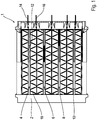
- FIG. 1 shows a side view of a heating register 1, as it is used for example for heating an air flow.
- This heating register 1 has a frame 2, in which four heating elements 4, 6, 8, 10 are used.
- Each heating element has, for example, PTC resistance elements 12, each of which can be controlled via electrical contacts 14, 16 (power supply, ground).
- the actual electrical contacting can take place, for example, via contact plates which are in electrical connection with the PTC modules. As in the exemplary embodiment shown, the electrical contacting can take place via the contact plates and via corrugated fins.
- each heating element has two corrugated fin elements 18 arranged on both sides of the PTC resistance elements 12, which are in thermal (and also electrical) contact with the PTC resistance elements 12 and transfer the heat given off by them to the air which flows through the heating register 1 perpendicular to the plane of the drawing.
- the structure of such heating register 1 is known, so that further explanations are unnecessary.
- FIG. 2 shows a corrugated fin base element 20 from which the corrugated fin elements 18 installed in the heating register 1 are formed.
- a basic element 20 essentially corresponds to the corrugated fin elements, as they are in the prior art mentioned at the beginning according to FIG DE 10 2013 108 357 A1 are disclosed.
- a base element 20 has a plurality of corrugated ribs 22, 24 bent in a meandering shape from a sheet metal strip, the apexes 26, 28 of which are shown in the illustration Figure 2 lie flush with each other or are arranged at a comparatively small distance from each other, which is significantly smaller than the width d of an apex.
- each apex 26, 28 merges into lamellar legs 30, 32, which are arranged in a V-shape with respect to one another, this V closes away from the associated vertex 26 towards the other vertex 28.
- beads in the illustrated embodiment three adjacent beads 34, 36, 38 are formed, which are formed by stamping during manufacture of the base element 20.
- the two outer beads 34, 38 are embossed inwards, towards the opposite lamella leg 30, while those of the middle beads 36 are formed to the right, towards the adjacent corrugated fin.
- a different bead geometry or a different number of beads can also be used.
- the corrugated fin 22, 24 is significantly stiffened in relation to beadless corrugated fins, so that the transport of the formed basic elements 20 from the bending tool to the next processing step is improved due to the increased rigidity.
- the base element 20 is shown in FIG Figure 4 applied with a tensile force F above.
- elements which transmit the tensile force act on the base element 20 at holding regions 40, 42 indicated by dash-dotted lines, in order to secure the base element 20 as in FIG Figure 4 shown to pull apart, so that the "negative" corrugated fin angle is widened in the basic state, so that the corrugated fin angle between the lamella legs 30, 32 is to a certain extent inverted.
- the distance D between two adjacent vertices is a multiple, for example more than 5 times the width d of a vertex.
- the distance D is almost zero, since the corrugated ribs 22, 24 rest against one another along their apices 26, 28.
- a corrugated fin element 18 is provided which can be produced with high precision at a predetermined apex distance D.
- a corrugated fin element 18 of this type is distinguished by a comparatively high rigidity with very simple manufacture.
- the method according to the invention can be carried out on cut basic elements or else on a basic element strand designed as an "endless belt", the cutting to length then taking place in a further process step.
- the leveling also ensures that a good contact surface is created for adjacent elements, such as PTC resistance elements 12 or contact plates.
- Figure 5 shows a three-dimensional representation of the corrugated fin element 18 produced by unfolding a basic element.
- this representation one can see the apexes 26, 28 flattened by leveling and the lamella legs 30, 32 made with a comparatively large V-angle ⁇ .
- This angle is for example more than 30 ° . In the specific embodiment, it is approximately 40 °.
Landscapes
- Engineering & Computer Science (AREA)
- Mechanical Engineering (AREA)
- Physics & Mathematics (AREA)
- Thermal Sciences (AREA)
- General Engineering & Computer Science (AREA)
- Chemical & Material Sciences (AREA)
- Combustion & Propulsion (AREA)
- Geometry (AREA)
- Resistance Heating (AREA)
- Cooling Or The Like Of Semiconductors Or Solid State Devices (AREA)
Description
- Die Erfindung betrifft ein Verfahren zum Herstellen eines durchströmbaren Wellrippenelementes für ein Heizregister oder für eine andere Heizvorrichtung gemäß dem Oberbegriff des Patentanspruches 1, ein nach einem derartigen Verfahren hergestelltes Wellrippenelement und ein Heizregister oder dergleichen mit einer Vielzahl derartiger Wellrippen.
- Für den Einsatz in Kraftfahrzeugen, insbesondere mit verbrauchsoptimierten Verbrennungsmotoren werden häufig elektrische Heizvorrichtungen zum Erwärmen von Luftströmen verwendet. Derartige Heizvorrichtungen sind für Hochvolt- und Niedervoltapplikationen in der Automobiltechnik, aber auch in der industriellen Technik, beispielsweise bei Schaltschrankbeheizungen, Zusatzheizungen für Niedrigenergiehäuser, etc. einsetzbar.
- Der Grundaufbau derartiger Heizvorrichtungen ist beispielsweise in der
EP 0 350 528 B1 der Anmelderin offenbart. Demgemäß hat die Heizvorrichtung mehrere Heizstufen, die je nach abzurufender Heizleistung ansteuerbar sind und im Prinzip aus zwei Radiatorelementen bestehen, zwischen denen Heizelemente, vorzugsweise PTC-Heizelemente (positive temperature coefficient) angeordnet sind. Diese Radiatorelemente sind als Wellrippen ausgeführt, die aus einem Blechband mäanderförmig gebogen sind, wobei die einzelnen Wellrippen in den an ihre Schenkel angrenzenden Bereichen wechselseitig an einander liegen. - In der
EP 2 022 293 B1 sind Wellrippenelemente gezeigt, bei denen zur Erhöhung einer Steifigkeit die Wellrippen mit einander verlötet sind. Dieses Dokument offenbart ein Verfahren mit der Merkmalen des Oberbegriffs des Anspruchs 1. - Aus der
EP 1 327 834 B1 ist es bekannt, zur Aussteifung der Wellrippenelemente diese mit an die Scheitel der Wellrippen angeordneten Kontaktblechen zu vercrimpen, so dass die Handhabung der an sich flexiblen Wellrippenelemente deutlich verbessert ist. - In der
DE 10 2013 108 357 A1 werden Wellrippenelemente beschrieben, bei denen zur Erhöhung der Steifigkeit die Scheitel der Wellrippen quer zur Längserstreckung des Wellrippenelementes mit einer Presskraft beaufschlagt werden, so dass diese Scheitel "abgeflacht" werden. Zusätzlich können in den sich an die Scheitel anschließenden Schenkeln der Wellrippen Sicken ausgebildet sein. - Eine weitere Möglichkeit besteht gemäß der
EP 2 022 293 B1 darin, ein Kontaktblech oder dergleichen mit den Scheiteln der Wellrippen zu verlöten. Alternativ ist es auch bekannt, die Wellrippen mit dem Kontaktblech durch Kleben zu verbinden. - Bei allen diesen Lösungen liegen die Scheitel der Wellrippen entweder seitlich an einander an oder stehen in einem sehr geringen Abstand. Diese geringen Abstände zwischen den Wellrippen eines Wellrippenelementes führen jedoch beim Durchströmen zu einem erhöhten Druckverlust und einer damit einhergehenden Verringerung der Strömungsgeschwindigkeit der Luft und einer erhöhten Geräuschbildung der Heizung.
- Prinzipiell kann man den Druckverlust verringern, indem die Scheitel zu einander beabstandet sind. Derartige Wellrippenelemente mit weit beabstandeten Wellrippen haben jedoch den Nachteil, dass sie nach dem Biegen noch flexibler als die Elemente mit geringem Scheitelabstand sind und des Weiteren aufgrund der deutlich vergrößerten Länge der Platzbedarf beim mäanderförmigen Biegen des Rohblechbandes groß ist. Ebenso ist es möglich, den Druckverlust durch Bildung von durchströmten Zonen ohne Wellrippenelemente zu verringern. Solche Lösungen mit Bypass haben jedoch den Nachteil, dass die Luftverteilung nicht mehr homogen ist.
- Demgegenüber liegt der Erfindung die Aufgabe zugrunde, ein Verfahren zu schaffen, mit dem die Herstellung eines mit geringem Druckverlust durchströmbaren Wellrippenelementes vereinfacht ist. Der Erfindung liegt des Weiteren die Aufgabe zugrunde, ein Wellrippenelement mit verringertem Durchströmungsquerschnitt und ein mit zumindest einem derartigen Wellrippenelement ausgeführtes Heizregister zu schaffen.
- Diese Aufgabe wird im Hinblick auf das Verfahren durch die Merkmalskombination des Patentanspruches 1, im Hinblick auf das Wellrippenelement durch die Merkmalskombination des Patentanspruches 8 und im Hinblick auf das Heizregister durch die Merkmalskombination des Patentanspruches 9 gelöst.
- Sonstige vorteilhafte Weiterbildungen der Erfindung sind Gegenstand der Unteransprüche.
- Erfindungsgemäß wird zum Herstellen eines Wellrippenelementes zunächst ein Wellrippen-Grundelement hergestellt, das im Prinzip einen herkömmlichen Aufbau hat, so dass die Scheitel der einzelnen Wellrippen entweder an einander anliegen oder in einem geringen Abstand zu einander angeordnet sind. Ein derartiges Wellrippen-Grundelement unterscheidet sich im Prinzip nicht von den eingangs beschriebenen herkömmlichen Wellrippenelementen.
- Im Anschluss an die Fertigung dieses Grundelementes werden dessen Endabschnitte dann mit einer Zugkraft in Längsrichtung des Wellrippenelementes beaufschlagt, so dass eine Aufweitung des Wellrippenelementes dahingehend erfolgt, dass sich der Abstand zwischen den Scheiteln durch plastische Verformung (Aufbiegen) vergrößert und sich somit die Gesamtlänge des Wellrippenelementes entsprechend vergrößert. Durch die damit einhergehende flachere Anstellung der Wellrippen wird einerseits der Strömungswiderstand beim Durchströmen deutlich verringert. Andererseits zeigte es sich überraschender Weise, dass sich durch das Aufbiegen der Grundelemente eine sehr gleichmäßige, reproduzierbare Wellenstruktur ausbilden lässt.
- Dementsprechend wird durch ein nach einem derartigen Verfahren hergestelltes Wellrippenelement bei geringem fertigungstechnischem Aufwand der Durchströmungswiderstand verringert.
- Ein mit einem derartigen Wellrippenelement ausgeführtes Heizregister ist bei einfachem Aufbau herkömmlichen Lösungen aufgrund der optimierten Strömungsgeschwindigkeit und der verringerten Geräuschbildung überlegen.
- Die Stabilität der Wellrippenelemente und der Wärmeaustausch quer zur Durchströmungsrichtung lassen sich durch Ausbilden von Sicken verbessern.
- Bei einer Variante einer derartigen Ausführungsform sind mehrere Sicken nebeneinander liegend angeordnet.
- Bei einem Ausführungsbeispiel der Erfindung erfolgt die Aufweitung derart, dass nach der Umformung der Abstand zwischen den Scheiteln ein Vielfaches der Scheitelbreite, vorzugsweise der Scheitelbreite des Grundelements, beträgt.
- Die Stabilität des Wellrippenelementes lässt sich weiter verbessern, wenn dieses oder das Grundelement vor oder nach dem Auffalten mit einer Presskraft beaufschlagt werden. Diese Presskraft ist dabei so gewählt, dass die Scheitel (Grundelement oder Wellrippenelement) plastisch abgeflacht oder "planiert" werden.
- Dieses "Planieren" kann somit nach der Ausbildung des Grundelementes oder nach dem Auffalten erfolgen. Prinzipiell kann auch auf dieses Planieren verzichtet werden.
- Ein bevorzugtes Ausführungsbeispiel der Erfindung wird im Folgenden anhand schematischer Zeichnungen näher erläutert. Es zeigen:
-
Figur 1 zeigt eine Prinzipdarstellung eines Heizregisters mit einer Vielzahl von Wellrippenelementen; -
Figur 2 eine dreidimensionale Darstellung eines Wellrippen-Grundelementes zur Fertigung eines Wellrippenelementes gemäßFigur 1 ; -
Figur 3 eine vergrößerte Teildarstellung des Grundelementes ausFigur 1 ; -
Figur 4 eine Abbildung zur Erläuterung des erfindungsgemäßen Verfahrens zur Herstellung eines Wellrippenelementes und -
Figur 5 ein nach einem derartigen Verfahren hergestelltes Wellrippenelement für ein Heizregister gemäßFigur 1 . -
Figur 1 zeigt eine Seitenansicht eines Heizregisters 1, wie es beispielsweise zur Erwärmung eines Luftstroms verwendet wird. Dieses Heizregister 1 hat einen Rahmen 2, in den vier Heizelemente 4, 6, 8, 10 eingesetzt sind. Jedes Heizelement hat beispielsweise PTC-Widerstandselemente 12, die jeweils über elektrische Kontakte 14, 16 (Stromzuführung, Masse) ansteuerbar sind. Die eigentliche elektrische Kontaktierung kann beispielsweise über Kontaktbleche erfolgen, die in elektrischer Wirkverbindung mit den PTC-Bausteinen stehen. Dabei kann - wie beim dargestellten Ausführungsbeispiel - die elektrische Kontaktierung über die Kontaktbleche und über Wellrippen erfolgen. - Selbstverständlich können anstelle der PTC-Widerstandselemente 12 auch Heizelemente anderer Bauart verwendet werden.
- Gemäß der Darstellung in
Figur 1 hat jedes Heizelement zwei beidseitig der PTC-Widerstandselemente 12 angeordnete Wellrippenelemente 18, die in thermischem (und auch elektrischem) Kontakt mit den PTC-Widerstandselementen 12 stehen und die von diesen abgegebene Wärme an die Luft übertragen, die das Heizregister 1 senkrecht zur Zeichenebene durchströmt. Der Aufbau derartiger Heizregister 1 ist bekannt, so dass weitere Erläuterungen entbehrlich sind. -
Figur 2 zeigt ein Wellrippen-Grundelement 20, aus dem die im Heizregister 1 verbauten Wellrippenelemente 18 gebildet werden. Ein derartiges Grundelement 20 entspricht im Wesentlichen den Wellrippenelementen, wie sie im eingangs genannten Stand der Technik gemäß derDE 10 2013 108 357 A1 offenbart sind. Demgemäß hat ein derartiges Grundelement 20 eine Vielzahl von mäanderförmig aus einem Blechband gebogene Wellrippen 22, 24, deren Scheitel 26, 28 in der Darstellung gemäßFigur 2 bündig an einander liegen oder aber in einem vergleichsweise geringen Abstand zu einander angeordnet sind, der deutlich geringer ist als die Breite d eines Scheitels. - Wie der vergrößerten Detaildarstellung gemäß
Figur 3 entnehmbar ist, geht jeder Scheitel 26, 28 in Lamellenschenkel 30, 32 über, die V-förmig zu einander angestellt sind, wobei sich dieses V vom zugeordneten Scheitel 26 weg zum anderen Scheitel 28 hin schließt. In jedem Lamellenschenkel 30, 32 sind Sicken, beim dargestellten Ausführungsbeispiel drei neben einander liegende Sicken 34, 36, 38 ausgebildet, die durch Stanzbiegen beim Herstellen des Grundelementes 20 ausgebildet werden. Dabei sind die beiden außen liegenden Sicken 34, 38 nach innen, zum gegenüber liegenden Lamellenschenkel 30 hin geprägt, während sich die der mittleren Sicke 36 nach rechts, zur benachbarten Wellrippe hin ausformt. Selbstverständlich kann auch eine andere Sickengeometrie oder eine andere Anzahl von Sicken verwendet werden. Durch diese Sicken wird die Wellrippe 22, 24 deutlich gegenüber sickenlosen Wellrippen ausgesteift, so dass der Transport der umgeformten Grundelemente 20 von dem Biegewerkzeug zum nächsten Verarbeitungsschritt aufgrund der erhöhten Steifigkeit verbessert ist. - Hinsichtlich weiterer Einzelheiten wird der Einfachheit halber auf die
DE 10 2013 108 357 A1 verwiesen. - Das derart gefertigte Grundelement 20 mit wechselseitig an einander anliegenden Wellrippen 22, 24 wird dann - wie in
Figur 4 dargestellt - in einem weiteren Fertigungsschritt zum Wellrippenelement 18 verarbeitet, wie es in dem Heizregister 1 verbaut ist. Dabei werden vorzugsweise - wie in derDE 10 2013 108 357 A1 - die verrundeten Scheitel 26, 28 mit einer Presskraft P (sieheFigur 4 oben) beaufschlagt. Diese Presskraft P wirkt quer zur Längserstreckung des Grundelementes 20. Durch diese Presskraft P wird erreicht, dass die ursprünglich verrundete Scheitel 26, 28 wie inFigur 4 unten dargestellt, abgeflacht (planiert) werden. Dieses Planieren kann beispielsweise durch ein Presswerkzeug erfolgen, das eine Vielzahl von Scheiteln 26, 28 gleichzeitig mit der Presskraft P beaufschlagt. - Nach diesem Abflachen wird das Grundelement 20 gemäß der Darstellung in
Figur 4 oben mit einer Zugkraft F beaufschlagt. Dazu greifen an strichpunktiert angedeuteten Haltebereichen 40, 42 die Zugkraft übertragende Elemente an dem Grundelement 20 an, um dieses wie inFigur 4 dargestellt, aus einander zu ziehen, so dass der im Grundzustand "negative" Wellrippenwinkel aufgeweitet wird, so dass der Wellrippenwinkel zwischen dem Lamellenschenkel 30, 32 gewissermaßen invertiert wird. Dies führt dazu, dass die Lamellenschenkel 30 beispielsweise vom oben liegenden Scheitel 26 zum nächsten darunter liegenden Scheitel 28 aus einander laufen. Diese aus einer plastischen Umformung des Grundelementes 20 resultierende Aufweitung führt dazu, dass die Gesamtlänge sich deutlich gegenüber der Gesamtlänge des Grundelementes 20 vergrößert. Beim dargestellten Ausführungsbeispiel beträgt beispielsweise der Abstand D zwischen zwei benachbarten Scheiteln ein Vielfaches, beispielsweise mehr als das 5-fache der Breite d eines Scheitels. Beim Grundelement 20 ist der Abstand D nahezu Null, da die Wellrippen 22, 24 entlang ihrer Scheitel 26, 28 an einander anliegen. - Es zeigte sich überraschender Weise, dass durch das erfindungsgemäße Verfahren, d.h. zunächst ein Grundelement 20 in nahezu herkömmlicher Bauweise auszubilden und dann dieses Grundelement 20 aufzuweiten, ein Wellrippenelement 18 bereitgestellt wird, das sich mit hoher Präzision bei vorgegebenem Scheitelabstand D produzieren lässt. Ein derartiges Wellrippenelement 18 zeichnet sich durch eine vergleichsweise große Steifigkeit bei sehr einfacher Herstellbarkeit aus.
- Es zeigt sich des Weiteren, dass durch das Planieren die Gefahr eines Einzugs, bei dem beispielsweise der zwischen zwei in
Figur 4 unten liegenden Scheiteln 28 angeordnete obere Scheitel 26 "eingezogen" wird und sich zu den beiden anderen Scheiteln 28 hin einwölbt, beseitigt ist. - Das erfindungsgemäße Verfahren kann an abgelängten Grundelementen oder aber auch an einem als "Endlosband" ausgebildeten Grundelementstrang ausgeführt werden, wobei das Ablängen dann in einem weiteren Verfahrensschritt erfolgt.
- Abweichend von der oben beschriebenen Vorgehensweise ist es auch möglich, wie in
Figur 4 unten gestrichelt angedeutet, die Presskraft P zum Abflachen (Planieren) der Scheitel 26, 28 in einem dem Auffalten durch die Kraft F nachfolgenden Arbeitsgang aufzubringen. - Durch das Planieren wird neben der Versteifung auch erreicht, dass eine gute Anlagefläche für angrenzende Elemente, wie zum Beispiel PTC-Widerstandselemente 12 oder Kontaktbleche geschaffen wird.
- Alternativ ist es auch möglich, den Arbeitsgang des Planierens ganz entfallen zu lassen.
-
Figur 5 zeigt eine dreidimensionale Darstellung des durch Auffalten eines Grundelementes hergestellten Wellrippenelementes 18. In dieser Darstellung erkennt man die durch Planieren abgeflachten Scheitel 26, 28 und die mit einem vergleichsweise großen V-Winkel α angestellten Lamellenschenkel 30, 32. Dieser Winkel beträgt beispielsweise mehr als 30°. Bei dem konkreten Ausführungsbeispiel liegt er bei etwa 40°. - Offenbart sind ein Verfahren zum Herstellen eines durchströmbaren Wellrippenelementes eines Heizregisters oder einer anderen Heizvorrichtung, ein nach einem derartigen Verfahren hergestelltes Wellrippenelement und ein mit derartigen Wellrippenelementen ausgeführtes Heizregister, bei denen die Wellrippenelemente durch Auffalten hergestellt sind.
-
- 1
- Heizregister
- 2
- Rahmen
- 4
- Heizelement
- 6
- Heizelement
- 8
- Heizelement
- 10
- Heizelement
- 12
- PTC-Widerstandselement
- 14
- Kontakt
- 16
- Kontakt
- 18
- Wellrippenelement
- 20
- Grundelement
- 22
- Wellrippe
- 24
- Wellrippe
- 26
- Scheitel
- 28
- Scheitel
- 30
- Lamellenschenkel
- 32
- Lamellenschenkel
- 34
- Sicke
- 36
- Sicke
- 38
- Sicke
- 40
- Haltebereich
- 42
- Haltebereich
Claims (9)
- Verfahren zum Herstellen eines umströmbaren Wellrippenelementes (18) für ein Heizregister (1) oder eine andere Heizvorrichtung, wobei das Wellrippenelement (18) eine Vielzahl von wellenförmig ausgebildeten Wellrippen (22, 24) hat, mit den Schritten:Herstellen eines Wellrippen-Grundelementes (20) derart, dass Scheitel (26, 28) der Wellrippen (22, 24) aneinander liegen oder in geringem Abstand zu einander angeordnet sind, dadurch gekennzeichnet, dass das Verfahren den folgenden Schritt aufweist: Beaufschlagen des Grundelementes (20) mit einer Zugkraft (F) derart, dass ein Abstand (D) zwischen den Scheiteln (26, 28) durch Umformen vergrößert wird und sich dadurch die Gesamtlänge des Wellrippenelementes (18) entsprechend vergrößert.
- Verfahren nach Patentanspruch 1, wobei bei dem Grundelement (20) in sich an die Scheitel (26, 28) anschließenden Lamellenschenkeln (30, 32) Sicken (34, 36, 38) ausgebildet sind.
- Verfahren nach Patentannspruch 2, wobei an den Lamellenschenkeln (30, 32) mehrere Sicken (34, 36, 38) neben einander liegend angeordnet sind.
- Verfahren nach Patentanspruch 1, 2 oder 3, wobei der Abstand (D) nach der Umformung ein Vielfaches einer Scheitelbreite (d) beträgt.
- Verfahren nach Patentanspruch 4, wobei der Abstand (D) nach der Umformung zumindest das 5-fache der Scheitelbreite (d) beträgt.
- Verfahren nach einem der vorhergehenden Patentansprüche, wobei die Scheitel (26, 28) quer zur Längserstreckung des Grund- oder Wellrippenelements (18, 20) mit einer Presskraft (P) beaufschlagt werden.
- Verfahren nach Patentanspruch 6, wobei die Presskraft (P) so gewählt ist, dass die Scheitel (26, 28) abgeflacht oder planiert werden.
- Wellrippenelement hergestellt nach einem Verfahren gemäß den Patentansprüchen 1 bis 7.
- Heizregister mit einer Vielzahl von Wellrippenelementen (18) gemäß Patentanspruch 8.
Priority Applications (1)
| Application Number | Priority Date | Filing Date | Title |
|---|---|---|---|
| PL16736878.6T PL3322942T5 (pl) | 2015-07-16 | 2016-07-08 | Sposób wytwarzania falistego elementu żeberkowego, falisty element żeberkowy i nagrzewnica |
Applications Claiming Priority (2)
| Application Number | Priority Date | Filing Date | Title |
|---|---|---|---|
| DE102015111571.9A DE102015111571A1 (de) | 2015-07-16 | 2015-07-16 | Verfahren zum Herstellen eines Wellrippenelementes, Wellrippenelement und Heizregister |
| PCT/EP2016/066345 WO2017009254A1 (de) | 2015-07-16 | 2016-07-08 | Verfahren zum herstellen eines wellrippenelementes, wellrippenelement und heizregister |
Publications (3)
| Publication Number | Publication Date |
|---|---|
| EP3322942A1 EP3322942A1 (de) | 2018-05-23 |
| EP3322942B1 true EP3322942B1 (de) | 2020-07-01 |
| EP3322942B2 EP3322942B2 (de) | 2023-11-22 |
Family
ID=56404123
Family Applications (1)
| Application Number | Title | Priority Date | Filing Date |
|---|---|---|---|
| EP16736878.6A Active EP3322942B2 (de) | 2015-07-16 | 2016-07-08 | Verfahren zum herstellen eines wellrippenelementes, wellrippenelement und heizregister |
Country Status (5)
| Country | Link |
|---|---|
| US (1) | US10875078B2 (de) |
| EP (1) | EP3322942B2 (de) |
| DE (1) | DE102015111571A1 (de) |
| PL (1) | PL3322942T5 (de) |
| WO (1) | WO2017009254A1 (de) |
Families Citing this family (5)
| Publication number | Priority date | Publication date | Assignee | Title |
|---|---|---|---|---|
| DE102016110023A1 (de) | 2015-11-13 | 2017-05-18 | Dbk David + Baader Gmbh | Heizeinheit und Wäschetrockner |
| EP3540354A1 (de) * | 2018-03-15 | 2019-09-18 | Mahle International GmbH | Wellrippenverbundmaterial für einen wärmetauscher |
| DE102018129408A1 (de) | 2018-11-22 | 2020-05-28 | Dbk David + Baader Gmbh | Vorrichtung zum Klimatisieren eines Fluids und Verfahren zum Betreiben einer derartigen Vorrichtung |
| US11340027B2 (en) * | 2019-07-15 | 2022-05-24 | Modine Manufacturing Company | Tube for a heat exchanger, and method of making the same |
| US12405070B2 (en) * | 2022-01-04 | 2025-09-02 | Carrier Corporation | Corrosion resistant microchannel heat exchanger |
Citations (12)
| Publication number | Priority date | Publication date | Assignee | Title |
|---|---|---|---|---|
| US2329789A (en) | 1939-11-16 | 1943-09-21 | Mccord Radiator & Mfg Co | Apparatus for making heatexchange elements |
| CH358773A (de) | 1958-05-12 | 1961-12-15 | Aluminium Ind Ag | Verfahren und Vorrichtung zur Herstellung von metallenen längsgewellten Bändern |
| GB1535781A (en) | 1976-04-08 | 1978-12-13 | Covrad Ltd | Corrugation-forming machines |
| JPS5890334A (ja) | 1981-11-24 | 1983-05-30 | Nissan Shatai Co Ltd | ラジエ−タフインの製造方法 |
| EP0350528B1 (de) | 1988-07-15 | 1992-04-01 | David & Baader DBK Spezialfabrik elektrischer Apparate und Heizwiderstände GmbH | Radiator |
| JPH08261678A (ja) | 1995-03-22 | 1996-10-11 | Nippondenso Co Ltd | コルゲートフィンとその製造方法 |
| EP1327834B1 (de) | 2002-01-15 | 2004-10-27 | David + Baader DBK Spezialfabrik Elektrischer Apparate und Heizwiderstände GmbH | Radiatorelement für eine Heizvorrichtung |
| EP2022293A1 (de) | 2006-05-24 | 2009-02-11 | Valeo Systemes Thermiques | Von einem luftstrom und einem elektrischen strom durchquertes metallwärmeenergieabfuhrelement |
| EP2031332B1 (de) | 2007-08-27 | 2010-09-15 | ABB Research LTD | Wärmetauscher für Komponenten der Leistungselektronik |
| EP2251115A1 (de) | 2007-02-01 | 2010-11-17 | Modine Manufacturing Company | Herstellungsverfahren für Flachrohre, Walzenstraße und Wärmetauscher mit solchen Flachrohren |
| WO2013153157A1 (de) | 2012-04-11 | 2013-10-17 | Behr Gmbh & Co. Kg | Wellrippe und verfahren zu deren herstellung |
| DE102013108357A1 (de) | 2013-08-02 | 2015-02-05 | Dbk David + Baader Gmbh | Lamellenelement und Verfahren zur Herstellung eines Lamellenelements |
Family Cites Families (13)
| Publication number | Priority date | Publication date | Assignee | Title |
|---|---|---|---|---|
| US2035403A (en) * | 1933-11-17 | 1936-03-24 | Fedders Mfg Co Inc | Heat exchange device |
| GB1301665A (de) * | 1969-05-09 | 1973-01-04 | ||
| JPS60221133A (ja) * | 1984-04-18 | 1985-11-05 | Meidensha Electric Mfg Co Ltd | コルゲ−トフインのピツチ調整装置 |
| JPS6434521A (en) * | 1987-07-29 | 1989-02-06 | Calsonic Corp | Corrugated fin forming device |
| JP2002263739A (ja) | 2001-03-12 | 2002-09-17 | Denso Corp | コルゲートフィンの製造方法 |
| WO2004003453A2 (en) * | 2002-06-28 | 2004-01-08 | Roger Paulman | Fin array for heat transfer assemblies and method of making same |
| JP4587707B2 (ja) * | 2004-02-19 | 2010-11-24 | カルソニックカンセイ株式会社 | コルゲートフィン製造装置及びコルゲートフィン製造方法 |
| JP2007245199A (ja) * | 2006-03-16 | 2007-09-27 | Calsonic Kansei Corp | 波板の製造装置 |
| US8453719B2 (en) * | 2006-08-28 | 2013-06-04 | Dana Canada Corporation | Heat transfer surfaces with flanged apertures |
| DE102009059283A1 (de) * | 2009-12-22 | 2011-06-30 | Caradon Stelrad B.V. | Verfahren zur Herstellung von Konvektorblechen für Heizkörper |
| JP2012007778A (ja) * | 2010-06-23 | 2012-01-12 | Komatsu Ltd | 熱交換器 |
| DE102012106157A1 (de) | 2012-07-09 | 2014-01-09 | Dbk David + Baader Gmbh | Lamellenelement und Verfahren zur Herstellung des Lamellenelements |
| JP6016677B2 (ja) * | 2013-03-15 | 2016-10-26 | カルソニックカンセイ株式会社 | フィン送り装置 |
-
2015
- 2015-07-16 DE DE102015111571.9A patent/DE102015111571A1/de active Pending
-
2016
- 2016-07-08 US US15/744,179 patent/US10875078B2/en active Active
- 2016-07-08 PL PL16736878.6T patent/PL3322942T5/pl unknown
- 2016-07-08 EP EP16736878.6A patent/EP3322942B2/de active Active
- 2016-07-08 WO PCT/EP2016/066345 patent/WO2017009254A1/de not_active Ceased
Patent Citations (12)
| Publication number | Priority date | Publication date | Assignee | Title |
|---|---|---|---|---|
| US2329789A (en) | 1939-11-16 | 1943-09-21 | Mccord Radiator & Mfg Co | Apparatus for making heatexchange elements |
| CH358773A (de) | 1958-05-12 | 1961-12-15 | Aluminium Ind Ag | Verfahren und Vorrichtung zur Herstellung von metallenen längsgewellten Bändern |
| GB1535781A (en) | 1976-04-08 | 1978-12-13 | Covrad Ltd | Corrugation-forming machines |
| JPS5890334A (ja) | 1981-11-24 | 1983-05-30 | Nissan Shatai Co Ltd | ラジエ−タフインの製造方法 |
| EP0350528B1 (de) | 1988-07-15 | 1992-04-01 | David & Baader DBK Spezialfabrik elektrischer Apparate und Heizwiderstände GmbH | Radiator |
| JPH08261678A (ja) | 1995-03-22 | 1996-10-11 | Nippondenso Co Ltd | コルゲートフィンとその製造方法 |
| EP1327834B1 (de) | 2002-01-15 | 2004-10-27 | David + Baader DBK Spezialfabrik Elektrischer Apparate und Heizwiderstände GmbH | Radiatorelement für eine Heizvorrichtung |
| EP2022293A1 (de) | 2006-05-24 | 2009-02-11 | Valeo Systemes Thermiques | Von einem luftstrom und einem elektrischen strom durchquertes metallwärmeenergieabfuhrelement |
| EP2251115A1 (de) | 2007-02-01 | 2010-11-17 | Modine Manufacturing Company | Herstellungsverfahren für Flachrohre, Walzenstraße und Wärmetauscher mit solchen Flachrohren |
| EP2031332B1 (de) | 2007-08-27 | 2010-09-15 | ABB Research LTD | Wärmetauscher für Komponenten der Leistungselektronik |
| WO2013153157A1 (de) | 2012-04-11 | 2013-10-17 | Behr Gmbh & Co. Kg | Wellrippe und verfahren zu deren herstellung |
| DE102013108357A1 (de) | 2013-08-02 | 2015-02-05 | Dbk David + Baader Gmbh | Lamellenelement und Verfahren zur Herstellung eines Lamellenelements |
Also Published As
| Publication number | Publication date |
|---|---|
| US20180200779A1 (en) | 2018-07-19 |
| EP3322942A1 (de) | 2018-05-23 |
| WO2017009254A1 (de) | 2017-01-19 |
| PL3322942T3 (pl) | 2020-11-16 |
| US10875078B2 (en) | 2020-12-29 |
| EP3322942B2 (de) | 2023-11-22 |
| DE102015111571A1 (de) | 2017-01-19 |
| PL3322942T5 (pl) | 2024-02-12 |
Similar Documents
| Publication | Publication Date | Title |
|---|---|---|
| EP3322942B2 (de) | Verfahren zum herstellen eines wellrippenelementes, wellrippenelement und heizregister | |
| DE60028660T2 (de) | Rohr sowie Verfahren und Vorrichtung zu seiner Herstellung | |
| DE102006038463A1 (de) | Wärmetauschereinheit und Verfahren zu ihrer Herstellung | |
| DE102012109801B4 (de) | Elektrische Heizvorrichtung | |
| EP1204495A1 (de) | Wärmetauscher | |
| DE112012006600T5 (de) | Verfahren zur Herstellung eines Wärmetauschers, Wärmetauscher und Klimaanlagenvorrichtung | |
| EP2390610B1 (de) | Lamellenwärmeübertrager | |
| DE102008003975A1 (de) | Wärmetauscher-Lamellenmodul, Wärmetauscher und elektrisches Heizmodul | |
| DE2627165A1 (de) | Geriffelter blechstreifen | |
| DE69606655T2 (de) | Schlangenförmiger Wärmetauscher und Verfahren zu seiner Herstellung | |
| DE20118511U1 (de) | Wärmeaustauschernetz und damit hergestellter Wärmeaustauscher | |
| DE69814020T2 (de) | Wärmetauscher und Verfahren zu dessen Herstellung | |
| EP2049860B1 (de) | Wellrippe und wärmetauscher | |
| EP2832464B1 (de) | Lamellenelement und Verfahren zur Herstellung eines Lamellenelements | |
| DE19723801A1 (de) | Wärmetauscher | |
| DE102012106157A1 (de) | Lamellenelement und Verfahren zur Herstellung des Lamellenelements | |
| DE202017102436U1 (de) | Wärmetauscher mit Mikrokanal-Struktur oder Flügelrohr-Struktur | |
| DE202009017777U1 (de) | Konvektorbleche für Heizkörper | |
| DE102008022391A1 (de) | Absorber, insbesondere für einen Sonnenkollektor und Verfahren zur Herstellung eines Absorbers für einen Sonnenkollektor | |
| DE102017112063A1 (de) | Lamelle, Verfahren und Vorrichtung zur Herstellung einer Lamelle und Wärmeaustauscher | |
| DE102006031676B4 (de) | Turbulenzblech, Verfahren zur Herstellung eines Turbulenzbleches und Verwendung eines Turbulenzbleches | |
| DE102006002932A1 (de) | Wärmetauscher und Herstellungsverfahren für Wärmetauscher | |
| EP3231524B1 (de) | Fertigungsverfahren für einen wärmeübertrager mit lamellen auf rohren | |
| DE602006000675T2 (de) | Wellrippe für integralgefertigten Wärmetäuscher | |
| DE102020000274A1 (de) | Verfahren zur Herstellung eines Rippen-Platten-Wärmetauschers |
Legal Events
| Date | Code | Title | Description |
|---|---|---|---|
| STAA | Information on the status of an ep patent application or granted ep patent |
Free format text: STATUS: THE INTERNATIONAL PUBLICATION HAS BEEN MADE |
|
| PUAI | Public reference made under article 153(3) epc to a published international application that has entered the european phase |
Free format text: ORIGINAL CODE: 0009012 |
|
| STAA | Information on the status of an ep patent application or granted ep patent |
Free format text: STATUS: REQUEST FOR EXAMINATION WAS MADE |
|
| 17P | Request for examination filed |
Effective date: 20180208 |
|
| AK | Designated contracting states |
Kind code of ref document: A1 Designated state(s): AL AT BE BG CH CY CZ DE DK EE ES FI FR GB GR HR HU IE IS IT LI LT LU LV MC MK MT NL NO PL PT RO RS SE SI SK SM TR |
|
| AX | Request for extension of the european patent |
Extension state: BA ME |
|
| DAV | Request for validation of the european patent (deleted) | ||
| DAX | Request for extension of the european patent (deleted) | ||
| REG | Reference to a national code |
Ref country code: DE Ref legal event code: R079 Ref document number: 502016010385 Country of ref document: DE Free format text: PREVIOUS MAIN CLASS: F24H0003040000 Ipc: B21D0013100000 |
|
| RIC1 | Information provided on ipc code assigned before grant |
Ipc: B21D 53/04 20060101ALI20191211BHEP Ipc: B21D 13/10 20060101AFI20191211BHEP Ipc: F28F 1/12 20060101ALI20191211BHEP Ipc: F24H 3/04 20060101ALI20191211BHEP Ipc: B60H 1/22 20060101ALI20191211BHEP Ipc: H05B 3/50 20060101ALI20191211BHEP Ipc: F24H 9/18 20060101ALI20191211BHEP Ipc: B21D 53/02 20060101ALI20191211BHEP |
|
| GRAP | Despatch of communication of intention to grant a patent |
Free format text: ORIGINAL CODE: EPIDOSNIGR1 |
|
| STAA | Information on the status of an ep patent application or granted ep patent |
Free format text: STATUS: GRANT OF PATENT IS INTENDED |
|
| INTG | Intention to grant announced |
Effective date: 20200123 |
|
| GRAS | Grant fee paid |
Free format text: ORIGINAL CODE: EPIDOSNIGR3 |
|
| GRAA | (expected) grant |
Free format text: ORIGINAL CODE: 0009210 |
|
| STAA | Information on the status of an ep patent application or granted ep patent |
Free format text: STATUS: THE PATENT HAS BEEN GRANTED |
|
| AK | Designated contracting states |
Kind code of ref document: B1 Designated state(s): AL AT BE BG CH CY CZ DE DK EE ES FI FR GB GR HR HU IE IS IT LI LT LU LV MC MK MT NL NO PL PT RO RS SE SI SK SM TR |
|
| REG | Reference to a national code |
Ref country code: AT Ref legal event code: REF Ref document number: 1285680 Country of ref document: AT Kind code of ref document: T Effective date: 20200715 Ref country code: CH Ref legal event code: EP |
|
| REG | Reference to a national code |
Ref country code: IE Ref legal event code: FG4D Free format text: LANGUAGE OF EP DOCUMENT: GERMAN |
|
| REG | Reference to a national code |
Ref country code: DE Ref legal event code: R096 Ref document number: 502016010385 Country of ref document: DE |
|
| REG | Reference to a national code |
Ref country code: NL Ref legal event code: FP |
|
| REG | Reference to a national code |
Ref country code: SE Ref legal event code: TRGR |
|
| REG | Reference to a national code |
Ref country code: LT Ref legal event code: MG4D |
|
| PG25 | Lapsed in a contracting state [announced via postgrant information from national office to epo] |
Ref country code: BG Free format text: LAPSE BECAUSE OF FAILURE TO SUBMIT A TRANSLATION OF THE DESCRIPTION OR TO PAY THE FEE WITHIN THE PRESCRIBED TIME-LIMIT Effective date: 20201001 |
|
| PG25 | Lapsed in a contracting state [announced via postgrant information from national office to epo] |
Ref country code: FI Free format text: LAPSE BECAUSE OF FAILURE TO SUBMIT A TRANSLATION OF THE DESCRIPTION OR TO PAY THE FEE WITHIN THE PRESCRIBED TIME-LIMIT Effective date: 20200701 Ref country code: CZ Free format text: LAPSE BECAUSE OF FAILURE TO SUBMIT A TRANSLATION OF THE DESCRIPTION OR TO PAY THE FEE WITHIN THE PRESCRIBED TIME-LIMIT Effective date: 20200701 Ref country code: ES Free format text: LAPSE BECAUSE OF FAILURE TO SUBMIT A TRANSLATION OF THE DESCRIPTION OR TO PAY THE FEE WITHIN THE PRESCRIBED TIME-LIMIT Effective date: 20200701 Ref country code: PT Free format text: LAPSE BECAUSE OF FAILURE TO SUBMIT A TRANSLATION OF THE DESCRIPTION OR TO PAY THE FEE WITHIN THE PRESCRIBED TIME-LIMIT Effective date: 20201102 Ref country code: LT Free format text: LAPSE BECAUSE OF FAILURE TO SUBMIT A TRANSLATION OF THE DESCRIPTION OR TO PAY THE FEE WITHIN THE PRESCRIBED TIME-LIMIT Effective date: 20200701 Ref country code: NO Free format text: LAPSE BECAUSE OF FAILURE TO SUBMIT A TRANSLATION OF THE DESCRIPTION OR TO PAY THE FEE WITHIN THE PRESCRIBED TIME-LIMIT Effective date: 20201001 Ref country code: HR Free format text: LAPSE BECAUSE OF FAILURE TO SUBMIT A TRANSLATION OF THE DESCRIPTION OR TO PAY THE FEE WITHIN THE PRESCRIBED TIME-LIMIT Effective date: 20200701 Ref country code: GR Free format text: LAPSE BECAUSE OF FAILURE TO SUBMIT A TRANSLATION OF THE DESCRIPTION OR TO PAY THE FEE WITHIN THE PRESCRIBED TIME-LIMIT Effective date: 20201002 |
|
| PG25 | Lapsed in a contracting state [announced via postgrant information from national office to epo] |
Ref country code: IS Free format text: LAPSE BECAUSE OF FAILURE TO SUBMIT A TRANSLATION OF THE DESCRIPTION OR TO PAY THE FEE WITHIN THE PRESCRIBED TIME-LIMIT Effective date: 20201101 Ref country code: RS Free format text: LAPSE BECAUSE OF FAILURE TO SUBMIT A TRANSLATION OF THE DESCRIPTION OR TO PAY THE FEE WITHIN THE PRESCRIBED TIME-LIMIT Effective date: 20200701 Ref country code: LV Free format text: LAPSE BECAUSE OF FAILURE TO SUBMIT A TRANSLATION OF THE DESCRIPTION OR TO PAY THE FEE WITHIN THE PRESCRIBED TIME-LIMIT Effective date: 20200701 |
|
| REG | Reference to a national code |
Ref country code: CH Ref legal event code: PL |
|
| REG | Reference to a national code |
Ref country code: DE Ref legal event code: R026 Ref document number: 502016010385 Country of ref document: DE |
|
| PG25 | Lapsed in a contracting state [announced via postgrant information from national office to epo] |
Ref country code: MC Free format text: LAPSE BECAUSE OF FAILURE TO SUBMIT A TRANSLATION OF THE DESCRIPTION OR TO PAY THE FEE WITHIN THE PRESCRIBED TIME-LIMIT Effective date: 20200701 |
|
| PLBI | Opposition filed |
Free format text: ORIGINAL CODE: 0009260 |
|
| PLAX | Notice of opposition and request to file observation + time limit sent |
Free format text: ORIGINAL CODE: EPIDOSNOBS2 |
|
| REG | Reference to a national code |
Ref country code: BE Ref legal event code: MM Effective date: 20200731 |
|
| PG25 | Lapsed in a contracting state [announced via postgrant information from national office to epo] |
Ref country code: LI Free format text: LAPSE BECAUSE OF NON-PAYMENT OF DUE FEES Effective date: 20200731 Ref country code: LU Free format text: LAPSE BECAUSE OF NON-PAYMENT OF DUE FEES Effective date: 20200708 Ref country code: CH Free format text: LAPSE BECAUSE OF NON-PAYMENT OF DUE FEES Effective date: 20200731 Ref country code: DK Free format text: LAPSE BECAUSE OF FAILURE TO SUBMIT A TRANSLATION OF THE DESCRIPTION OR TO PAY THE FEE WITHIN THE PRESCRIBED TIME-LIMIT Effective date: 20200701 Ref country code: RO Free format text: LAPSE BECAUSE OF FAILURE TO SUBMIT A TRANSLATION OF THE DESCRIPTION OR TO PAY THE FEE WITHIN THE PRESCRIBED TIME-LIMIT Effective date: 20200701 Ref country code: SM Free format text: LAPSE BECAUSE OF FAILURE TO SUBMIT A TRANSLATION OF THE DESCRIPTION OR TO PAY THE FEE WITHIN THE PRESCRIBED TIME-LIMIT Effective date: 20200701 Ref country code: EE Free format text: LAPSE BECAUSE OF FAILURE TO SUBMIT A TRANSLATION OF THE DESCRIPTION OR TO PAY THE FEE WITHIN THE PRESCRIBED TIME-LIMIT Effective date: 20200701 Ref country code: IT Free format text: LAPSE BECAUSE OF FAILURE TO SUBMIT A TRANSLATION OF THE DESCRIPTION OR TO PAY THE FEE WITHIN THE PRESCRIBED TIME-LIMIT Effective date: 20200701 |
|
| 26 | Opposition filed |
Opponent name: MAHLE INTERNATIONAL GMBH Effective date: 20210330 |
|
| PG25 | Lapsed in a contracting state [announced via postgrant information from national office to epo] |
Ref country code: AL Free format text: LAPSE BECAUSE OF FAILURE TO SUBMIT A TRANSLATION OF THE DESCRIPTION OR TO PAY THE FEE WITHIN THE PRESCRIBED TIME-LIMIT Effective date: 20200701 Ref country code: BE Free format text: LAPSE BECAUSE OF NON-PAYMENT OF DUE FEES Effective date: 20200731 |
|
| PG25 | Lapsed in a contracting state [announced via postgrant information from national office to epo] |
Ref country code: SK Free format text: LAPSE BECAUSE OF FAILURE TO SUBMIT A TRANSLATION OF THE DESCRIPTION OR TO PAY THE FEE WITHIN THE PRESCRIBED TIME-LIMIT Effective date: 20200701 |
|
| PLBB | Reply of patent proprietor to notice(s) of opposition received |
Free format text: ORIGINAL CODE: EPIDOSNOBS3 |
|
| PG25 | Lapsed in a contracting state [announced via postgrant information from national office to epo] |
Ref country code: SI Free format text: LAPSE BECAUSE OF FAILURE TO SUBMIT A TRANSLATION OF THE DESCRIPTION OR TO PAY THE FEE WITHIN THE PRESCRIBED TIME-LIMIT Effective date: 20200701 Ref country code: IE Free format text: LAPSE BECAUSE OF NON-PAYMENT OF DUE FEES Effective date: 20200708 |
|
| PG25 | Lapsed in a contracting state [announced via postgrant information from national office to epo] |
Ref country code: TR Free format text: LAPSE BECAUSE OF FAILURE TO SUBMIT A TRANSLATION OF THE DESCRIPTION OR TO PAY THE FEE WITHIN THE PRESCRIBED TIME-LIMIT Effective date: 20200701 Ref country code: MT Free format text: LAPSE BECAUSE OF FAILURE TO SUBMIT A TRANSLATION OF THE DESCRIPTION OR TO PAY THE FEE WITHIN THE PRESCRIBED TIME-LIMIT Effective date: 20200701 Ref country code: CY Free format text: LAPSE BECAUSE OF FAILURE TO SUBMIT A TRANSLATION OF THE DESCRIPTION OR TO PAY THE FEE WITHIN THE PRESCRIBED TIME-LIMIT Effective date: 20200701 |
|
| PG25 | Lapsed in a contracting state [announced via postgrant information from national office to epo] |
Ref country code: MK Free format text: LAPSE BECAUSE OF FAILURE TO SUBMIT A TRANSLATION OF THE DESCRIPTION OR TO PAY THE FEE WITHIN THE PRESCRIBED TIME-LIMIT Effective date: 20200701 |
|
| REG | Reference to a national code |
Ref country code: AT Ref legal event code: MM01 Ref document number: 1285680 Country of ref document: AT Kind code of ref document: T Effective date: 20210708 |
|
| PG25 | Lapsed in a contracting state [announced via postgrant information from national office to epo] |
Ref country code: AT Free format text: LAPSE BECAUSE OF NON-PAYMENT OF DUE FEES Effective date: 20210708 |
|
| APAH | Appeal reference modified |
Free format text: ORIGINAL CODE: EPIDOSCREFNO |
|
| APBM | Appeal reference recorded |
Free format text: ORIGINAL CODE: EPIDOSNREFNO |
|
| APBP | Date of receipt of notice of appeal recorded |
Free format text: ORIGINAL CODE: EPIDOSNNOA2O |
|
| APBU | Appeal procedure closed |
Free format text: ORIGINAL CODE: EPIDOSNNOA9O |
|
| P01 | Opt-out of the competence of the unified patent court (upc) registered |
Effective date: 20230525 |
|
| PUAH | Patent maintained in amended form |
Free format text: ORIGINAL CODE: 0009272 |
|
| STAA | Information on the status of an ep patent application or granted ep patent |
Free format text: STATUS: PATENT MAINTAINED AS AMENDED |
|
| 27A | Patent maintained in amended form |
Effective date: 20231122 |
|
| AK | Designated contracting states |
Kind code of ref document: B2 Designated state(s): AL AT BE BG CH CY CZ DE DK EE ES FI FR GB GR HR HU IE IS IT LI LT LU LV MC MK MT NL NO PL PT RO RS SE SI SK SM TR |
|
| REG | Reference to a national code |
Ref country code: DE Ref legal event code: R102 Ref document number: 502016010385 Country of ref document: DE |
|
| REG | Reference to a national code |
Ref country code: SE Ref legal event code: RPEO |
|
| REG | Reference to a national code |
Ref country code: NL Ref legal event code: FP |
|
| PGFP | Annual fee paid to national office [announced via postgrant information from national office to epo] |
Ref country code: PL Payment date: 20250606 Year of fee payment: 10 |
|
| PGFP | Annual fee paid to national office [announced via postgrant information from national office to epo] |
Ref country code: NL Payment date: 20250723 Year of fee payment: 10 |
|
| PGFP | Annual fee paid to national office [announced via postgrant information from national office to epo] |
Ref country code: DE Payment date: 20250610 Year of fee payment: 10 |
|
| PGFP | Annual fee paid to national office [announced via postgrant information from national office to epo] |
Ref country code: GB Payment date: 20250724 Year of fee payment: 10 |
|
| PGFP | Annual fee paid to national office [announced via postgrant information from national office to epo] |
Ref country code: FR Payment date: 20250723 Year of fee payment: 10 |
|
| PGFP | Annual fee paid to national office [announced via postgrant information from national office to epo] |
Ref country code: SE Payment date: 20250723 Year of fee payment: 10 |