EP3318699A1 - Verschlussanordnung zum abdecken von offenen behältern mit einer darin befindlichen flüssigkeit - Google Patents
Verschlussanordnung zum abdecken von offenen behältern mit einer darin befindlichen flüssigkeit Download PDFInfo
- Publication number
- EP3318699A1 EP3318699A1 EP17196056.0A EP17196056A EP3318699A1 EP 3318699 A1 EP3318699 A1 EP 3318699A1 EP 17196056 A EP17196056 A EP 17196056A EP 3318699 A1 EP3318699 A1 EP 3318699A1
- Authority
- EP
- European Patent Office
- Prior art keywords
- base
- closure arrangement
- base element
- closure
- hollow chamber
- Prior art date
- Legal status (The legal status is an assumption and is not a legal conclusion. Google has not performed a legal analysis and makes no representation as to the accuracy of the status listed.)
- Granted
Links
Images


Classifications
-
- E—FIXED CONSTRUCTIONS
- E04—BUILDING
- E04H—BUILDINGS OR LIKE STRUCTURES FOR PARTICULAR PURPOSES; SWIMMING OR SPLASH BATHS OR POOLS; MASTS; FENCING; TENTS OR CANOPIES, IN GENERAL
- E04H4/00—Swimming or splash baths or pools
- E04H4/06—Safety devices; Coverings for baths
- E04H4/08—Coverings consisting of rigid elements, e.g. coverings composed of separate or connected elements
- E04H4/082—Coverings consisting of rigid elements, e.g. coverings composed of separate or connected elements composed of flexibly or hingedly-connected slat-like elements, which may or may not be wound-up on a fixed axis
Definitions
- the invention relates to a closure arrangement for covering open containers with a liquid therein, in particular for covering swimming pools, which comprises at least two base elements, wherein the base member has a hollow chamber, wherein at least one base member having one of its longitudinal sides with one of these opposite longitudinal side of an adjacent Base element is connected at least partially movable via at least one connecting means and at which, having the longitudinal side opposite the longitudinal side connected to the connecting means at least one connecting device.
- each roller shutter rod a number of closed chambers (hollow chambers), a cross-sectionally T-shaped coupling web and a coupling web receiving, having a slot-like receptacle, and wherein each roller shutter rod on its upper side is made of transparent plastic and its Bottom coated or colored with dark color.
- These roller shutter bars are costly to produce in their production in particular by the different coating or coloring of individual components.
- roller shutter bars and the pool covers to be manufactured therefrom Another disadvantage of these roller shutter bars and the pool covers to be manufactured therefrom is that at least the two hollow chambers are to be sealed in a liquid-tight manner at the free ends of each roller shutter bar, so that the swimming pool cover can only fulfill its function.
- This hollow body of metal or plastic with at least one axial chamber partition wall and a watertight closure which consists of a cap provided with filling and vents, the form-fitting in each chamber of the hollow body insertable plugs, at which at a distance filling the cross section of the respective chamber Piston plate is fixed and in which the cavity located between the piston plate and cap is filled with a permanently elastic filler, preferably based on plastic, wherein in the cap at least one leading over the chamber partition wall overflow channel is provided for the filler.
- the hollow body is designed as a roller shutter profile and should be joined together to form a pool cover, which rests on the water surface.
- each individual hollow chamber of a roller shutter rod is to be provided with a special geometry having a sealing device, which consists here of a piston plate and a permanently elastic substance to be introduced from the outside between them.
- such a pool cover is extremely expensive in the production of roller shutter profiles and in particular in the manufacture of individual roller shutter bars, which are liquid-tight to close at its two free ends and assemble into a pool cover.
- a closure arrangement for covering open containers with a liquid therein, in particular for covering swimming pools which comprises at least two base elements, wherein the base member has a hollow chamber, wherein at least one base member having one of its longitudinal sides with one of these at least partially movably connected via at least one connecting means and at which, with the connecting means connected longitudinal side opposite longitudinal side has at least one connecting device is characterized in that the hollow chamber of the base member comprises a material whose density is between 0.01 and 0.7 g / cm 3 measured according to DIN 1183 is that at least one, a fixing elements receiving opening is arranged on at least one connecting means of the base member.
- the closure assembly according to the invention thus has over the previously known prior art, a higher buoyancy in their intended use and can thus be used as a cost-effective and visually appealing closure assembly for already built, leaking pool covers from hollow chamber profiles with lateral sealing elements.
- the material arranged in the hollow chamber of the base element is selected, preferably from polyvinyl chloride (PVC), polyurethane (PU), acrylonitrile-butadiene-styrene (ABS), polystyrene (PS), acrylic ester Styrene-acrylonitrile (ASA), polypropylene (PP), polyethylene (PE), polyethylene terephthalate (PET), polycarbonate (PC), polymethyl methacrylate (PMMA) or copolymers thereof.
- PVC polyvinyl chloride
- PU polyurethane
- ABS acrylonitrile-butadiene-styrene
- PS polystyrene
- ASA acrylic ester Styrene-acrylonitrile
- PP polyprop
- closure arrangement according to the invention is designed in extreme weather conditions, such as in particular hail, in such a way that there are no holes in the individual base elements can be realized by breaking through hailstones.
- a further advantage of the closure arrangement according to the invention is, in particular, that it surprisingly, when used as intended, has a thermal conductivity of about 0.037 W / Km according to the HOT DISK method according to ISO 22007.
- the closure arrangement according to the invention can be designed such that the material of the base element has a transmittance of at least 80% measured according to ISO 13468-2 over its thickness for visible light.
- the material arranged in the hollow chamber of the base element can have a dark color, in particular black.
- the receiving opening of the connecting device is arranged approximately parallel to the longitudinal side of the base member.
- a likewise advantageous embodiment of the closure arrangement according to the invention is designed such that the receiving opening of the connecting device is arranged approximately opposite the receiving opening of the base element.
- the fixing element is non-positively and / or materially connected to the base element.
- a closure assembly according to the invention can be provided, which can be adapted very quickly and easily the different geometries of swimming pools on site and in which the assembly of the individual base elements to a closure assembly according to the invention and their fixation, especially against possible longitudinal displacements is easy and without tools possible .
- Another advantage is that with a non-positive connection, an interchangeability of individual base elements is easily possible, especially in case of damage.
- closure arrangement according to the invention is designed with increased stability requirements or by certain national safety regulations such that the fixing element is adhesively bonded to the base element via adhesive systems known per se.
- the fixing element has a base and at least one male element.
- Such a fixing can also be produced inexpensively and economically, for example. In the injection molding but also in the so-called 3D printing.
- closure arrangement according to the invention is that the male element of the fixing element is in operative connection with the receiving opening of the base elements.
- the male member is formed so that it can be mounted with little effort and without tools from individual base elements to a closure arrangement according to the invention.
- the closure arrangement according to the invention is also advantageously designed such that the fixing element has at least one support element on its base.
- This support element of the fixing element is designed so that it leads to a further and better and correct mounting of the fixing element in the base element and to a security against rotation during assembly via the male in the receiving opening of the base elements under normal use of the closure assembly according to the invention.
- the base of the fixing element is advantageously designed so that it has a base area which corresponds approximately to the base of the base profile.
- the base elements of a polymeric material preferably of polyvinyl chloride (PVC), polyurethane (PU), acrylonitrile-butadiene-styrene (ABS), polystyrene (PS), acrylic ester-styrene-acrylonitrile (ASA ), Polypropylene (PP), polyethylene (PE), polyethylene terephthalate (PET), polycarbonate (PC), polymethyl methacrylate (PMMA) or copolymers thereof.
- PVC polyvinyl chloride
- PU polyurethane
- ABS acrylonitrile-butadiene-styrene
- PS polystyrene
- ASA acrylic ester-styrene-acrylonitrile
- PP Polypropylene
- PE polyethylene
- PET polyethylene terephthalate
- PC polycarbonate
- PMMA polymethyl methacrylate
- the base elements of the closure arrangement according to the invention are designed so that they have a wall thickness in the range of about 0.05 to 5.0 mm, preferably 0.1 to 2.5 mm. In this way, advantageously, an economical and cost-effective production of the basic elements forming the closure arrangement according to the invention can be realized.
- the closure arrangement according to the invention is further characterized in that the base element in cross-section is approximately polygonal, prismatic, round, oval, elliptical and the like.
- the base element in cross-section is approximately polygonal, prismatic, round, oval, elliptical and the like.
- the closure arrangement according to the invention is designed such that the material arranged in the hollow chamber of the base element is arranged spaced apart from the wall surrounding the hollow chamber via at least one spacer layer.
- the closure arrangement according to the invention can thus be provided economically and cost-effectively in a number of different colors, due to the coloring of the spacer layer and / or of the base element.
- a further advantage of the closure arrangement according to the invention is that the material arranged in the hollow chamber of the base element is cohesively arranged via the spacer layer itself with the wall surrounding the hollow chamber.
- the spacer layer can be formed as a per se known adhesive system.
- the material of the spacer layer is selected from the group of polyamides (PA); the polyurethanes (PUR), the polyolefins, especially polyethylene (PE); the amorphous polyalphaolefins (APAO); the styrene or styrene-butylene copolymers; the thermoplastic elastomer (TPE), in particular the thermoplastic urethane-based elastomers (TPE-U), the thermoplastic copolyamides (TPE-A), the thermoplastic polyester elastomers (TPE-E); the ethylene-vinyl acetate copolymer (EVAC) and the like.
- PA polyamides
- PUR polyurethanes
- PUR polyolefins
- PE polyethylene
- APAO amorphous polyalphaolefins
- styrene or styrene-butylene copolymers the thermoplastic elastomer
- TPE thermoplastic e
- the spacer layer has a thickness of about 0.05 mm to about 5 mm, preferably 0.05 to about 1.5 mm.
- At least one base element has at least one light element, such as LED lights and the like, which impart a visually appealing design and additional functionalities to the closure arrangement according to the invention.
- These light elements can be introduced both in the manufacturing process of forming the closure assembly according to the invention basic elements with, as well as subsequently quickly and easily attached to the closure assembly.
- At least one base element has at least one sensor element, such as temperature measuring sensors, light sensors, water composition sensors, length measuring sensors, position sensors, distance sensors and the like, which give the closure assembly according to the invention new functionalities, without their intended Total use is reduced or reduced.
- sensor element such as temperature measuring sensors, light sensors, water composition sensors, length measuring sensors, position sensors, distance sensors and the like
- these sensor elements can be introduced or attached in the manufacturing process of the basic elements forming the closure arrangement according to the invention, but on the other hand it is also possible to subsequently integrate them into the closure arrangement according to the invention.
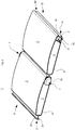
- FIG. 1 is a detailed perspective view of a closure assembly 1 of the invention for covering open containers with a liquid therein, in particular for covering swimming pools shown.
- the closure arrangement 1 comprises a plurality of base elements 2, each base element 2 having a longitudinal side 21, 22 connected at least in sections to a longitudinal side 21, 22 of an adjacent base element 2 that is opposite thereto, via at least one connection means 3 is and at the, with the connecting means 3 connected longitudinal side 21 opposite, longitudinal side 22 has at least one connecting device 4.
- the closure arrangement 1 according to the invention is furthermore designed such that the hollow chamber 5 of the base element 2 has a material whose density over the cross section is approximately in the range from 0.05 to 0.1 g / cm 3 .
- closure arrangement 1 is designed so that at least one, a fixing element 7 receiving, receiving opening disposed on the connecting device 4 of the base member 2, which is covered in this embodiment by the fixing element 7.
- the fixing elements arranged at the free ends of the base elements 2 of the closure arrangement 1 according to the invention is advantageously designed and dimensioned such that, when the closure arrangement 1 according to the invention is used properly, in particular for covering swimming pools, over the entire surface of the closure arrangement 1 according to the invention as a spacer to the edge of the cover swimming pool functions.
- the free ends of the base elements 2 of the closure assembly 1 according to the invention come into direct contact with the edge of the example swimming pool.
- FIG. 2 is a detailed perspective view of a closure assembly 1 of the invention for covering open containers with a liquid therein, in particular for covering swimming pools shown.
- closure arrangement 1 according to the invention comprises two base elements 2.
- the base elements 2 are further designed such that at least one base element 2 with one of its longitudinal sides 21, 22 with a longitudinal side 21, 22 opposite thereto an adjacent base element 2 at least partially movable via a connecting means 3 are connected and at the, connected to the connecting means 3 longitudinal side 21 opposite longitudinal side 22 at least one connecting device 4.
- the arranged on the longitudinal side 21 of the base member 2 connecting means 3 is formed in this embodiment as an integrally disposed on the base member 2, two mutually projecting hook elements 31, 32 having hooks.
- the arranged on the longitudinal side 22 of the base member 2 connecting device 4 is formed in this embodiment, that it has a receiving gap 40 which is bounded by two curved ends 41, 42 of the connecting device 4, which are arranged approximately parallel to each other opposite.
- the base elements 2 of the closure assembly 1 according to the invention are formed in this embodiment so that they have a hollow chamber 5.
- a material is arranged whose density is between 0.01 and 0.7 g / cm 3 measured according to DIN 1183.
- the hollow chamber 5 of the base element 2 of the closure assembly 1 according to the invention is completely filled by this material.
- the material arranged in the hollow chamber 5 of the base element 2 is a foam based on a polystyrene (PS) with a density of about 0.2 g / cm 3 measured according to DIN 1183.
- PS polystyrene
- closure arrangement 1 according to the invention for covering open containers with a liquid therein, in particular for covering swimming pools is designed so that advantageously on the one hand a certain insulating effect for the, mostly heated liquids located under the closure arrangement 1 according to the invention, realized and on the other hand, the closure assembly 1 according to the invention is formed in extreme weather conditions such as hail in particular so that in the individual base elements 2 no holes can be realized by a penetration of hailstones.
- a further advantage of the closure arrangement 1 according to the invention is, in particular, that it has a thermal conductivity of about 0.037 W / km according to the HOT DISK method according to ISO 22007 when used as intended.
- the material arranged in the hollow chamber 5 of the base element 2 is designed as a closed-cell foam and / or open-cell foam and / or mixed cellular foam and / or integral foam.
- the material arranged in the hollow chamber 5 of the base element 2 can be produced from thermoplastic and / or elastomeric and / or duroplastic foam.
- the closure arrangement 1 for covering open containers with a liquid therein, in particular for covering swimming pools, generally comprises at least two base elements 2, wherein a base element 2 with the connection means 3 arranged on its longitudinal side 21 with the adjacent base element 2 on the Long side 22 arranged connecting device 4 is connected.
- the base elements 2 are not mounted by longitudinal displacement and guiding the connecting means 3 in the connecting device 4 to a closure assembly 1 according to the invention.
- the hook elements 31, 32 of the connecting means 3 are positioned relative to the connecting device 4 so that the hook member 31 hooked by the receiving gap 40 behind the curved end 41 of the connecting device 4 and the other hook member 32 of the connecting means 3 by a small force behind the curved end 42 of the connecting device 4 can be latched.
- connection arrangement 1 is furthermore designed so that at least one receiving opening 6 accommodating a fixing element 7 is arranged on at least one connecting device 4 of the base element 2.
- the receiving opening 6 of the connecting device 4 of the base element 2 is arranged approximately parallel to the longitudinal side 22 of the base element 2.
- the closure arrangement 1 is designed such that the receiving opening 6 of the connecting device 4 is arranged opposite to the hollow chamber 5 of the base element 2.
- the receiving opening 6 of the base member 2 is formed approximately circular in cross-section in this embodiment and arranged over the entire longitudinal side 22 of the base member 2.
- the closure arrangement 1 according to the invention for covering open containers with a liquid therein, in particular for covering swimming pools, is now produced according to the dimensions of the container or the swimming pool in such a way that individual base elements 2 of a defined length are made available.
- the base elements 2 are then introduced via the arranged on the longitudinal side 21 connecting means 3 of the respective adjacent base member 2 arranged on the longitudinal side 22 connecting means 4 until the free ends of the base elements 2 are arranged at a same distance from each other.
- the fixing element 7 has a base 70 on which an insertion element 71, not shown, is arranged.
- the fixing element 7 is non-positively connected to the base element 2 via the insertion element 71 (not shown).
- the protruding from the base 70 of the fixing element 7 male member 71 is disposed over its entire length in the receiving opening 6 of the base member 2.
- the base 70 of the fixing element 7 covers and closes both the receiving opening 6 and the enclosed by the curved ends 41, 42 of the connecting device 4 receiving space 43, so that it is also covered.
- the closure arrangement 1 according to the invention is furthermore designed such that the material arranged in the hollow chamber 5 of the base element 2 is arranged at a distance from the wall surrounding the hollow chamber 5 via a spacer layer 8.
- This spacer layer 8 can be formed in a manner known per se as an adhesive system and leads to an even better cohesive connection of the arranged in the hollow chamber 5 of the base member 2 material.
- the base elements 2 of the closure assembly 1 according to the invention are made of a polymeric material, in particular of polyvinyl chloride (PVC).
- PVC polyvinyl chloride
- the base elements 2 of the closure assembly 1 according to the invention are formed so that they have a wall thickness in the range of about 0.05 to 5.0 mm, preferably 0.1 to 2.5 mm. In this way, advantageously, an economical and cost-effective production of the closure element 1 according to the invention forming basic elements 2 can be realized.
- the base elements 2 are made of a polymeric material having a transmittance of at least 80% measured according to ISO 13468-2 over its thickness for visible light.
- the arranged in the hollow chamber 5 of the base member 2 material and / or the spacer layer 8 can be made in different colors, especially in black, and thus alone give the closure assembly 1 according to the invention a visually pleasing appearance.
- FIG. 3 a perspective detailed representation of the fixing element 7 of the closure assembly 1 according to the invention is shown.
- the fixing element 7 has in this embodiment, a base 70, on which at least one male element 71 is arranged.
- the base 70 of the fixing element 7 is approximately oval in this exemplary embodiment and has an insertion element 71 arranged approximately orthogonally to the base surface of the base 70.
- the male element 71 of the fixing element 7 has an approximately arrow-shaped insertion tip 74 at its free end protruding from the base 70 of the fixing element 7. Between the arrow-shaped insertion tip 74 and the base 70 of the fixing 7, the male member 71 is formed so that it has a plurality of approximately orthogonally projecting, approximately parallel spaced webs 75.
- the fixing device 7 When the fixing device 7 is used as intended, in particular for producing a closure arrangement 1 according to the invention, it is positioned at two base elements 2 rotatably connected to one another via the connection means 3 in the connection device 4 such that the arrow-shaped insertion tip 74 is arranged opposite the receiving opening 6 of the connection device 4 and over the base 70, the fixing element frictionally engageable with the receiving opening 6 of the base member 2 in operative connection.
- the fixing element 7 of the closure arrangement 1 according to the invention is further designed such that it has a support element 72, 73.
- the support element 72, 73 is likewise arranged approximately orthogonally at the base 70 of the fixing element 7 at a distance from the insertion element 71 and has an approximately oval geometry in cross-section.
- the supporting elements 72, 73 are arranged in the connecting device 4 arranged on the longitudinal side 22 of the base element 2 such that they are spaced from the receiving opening 6 with respect to the curved ends 41, 42 of the connecting device 4 are arranged and thus prevent rotation of the fixing element 7 about its axis formed on the male 71.
- the support elements 72, 73 of the fixing 7 are materially fixed by known adhesive systems and / or by a weld in the receiving space 40 of the connecting device 4 and thus on the one hand prevent longitudinal displacement of the base elements 2 arranged one another and on the other hand also ensure the security against rotation of the closure assembly 1 according to the invention.
Landscapes
- Engineering & Computer Science (AREA)
- Architecture (AREA)
- Civil Engineering (AREA)
- Structural Engineering (AREA)
- Closures For Containers (AREA)
- Toys (AREA)
Abstract
Description
- Die Erfindung betrifft eine Verschlussanordnung zum Abdecken von offenen Behältern mit einer darin befindlichen Flüssigkeit, insbesondere zum Abdecken von Schwimmbecken, welche zumindest zwei Basiselemente umfasst, wobei das Basiselement eine Hohlkammer aufweist, wobei wenigstens ein Basiselement mit einer seiner Längsseiten mit einer dieser gegenüberliegenden Längsseite eines benachbarten Basiselements zumindest abschnittsweise beweglich über wenigstens ein Verbindungsmittel verbunden ist und an der, der mit dem Verbindungsmittel verbundenen Längsseite gegenüberliegenden Längsseite wenigstens eine Verbindungseinrichtung aufweist.
- Derartige Verschlussanordnungen zum Abdecken von offenen Behältern mit einer darin befindlichen Flüssigkeit sind im Stand der Technik beschrieben.
- So beschreibt beispielsweise die
DE 196 46 117 C1 einen Solarrollladen für Schwimmbadabdeckungen, bei der jeder Rollladenstab eine Anzahl geschlossener Kammern (Hohlkammern), einen im Querschnitt T-förmigen Kupplungssteg und eine den Kupplungssteg aufnehmende, eine schlitzartige Öffnung aufweisende Aufnahme, besitzt und wobei jeder Rollladenstab auf seiner Oberseite aus transparentem Kunststoff besteht und seine Unterseite mit dunkler Farbe beschichtet oder durchgefärbt ist. Diese Rollladenstäbe sind in ihrer Herstellung insbesondere durch die unterschiedliche Beschichtung bzw. Färbung einzelner Bestandteile kostenaufwendig herzustellen. - Ein weiterer Nachteil dieser Rollladenstäbe und der daraus herzustellenden Schwimmbadabdeckungen besteht darin, dass mindestens die zwei Hohlkammern an den freien Enden eines jeden Rollladenstabes flüssigkeitsdicht zu verschließen sind, sodass die Schwimmbadabdeckung ihre Funktion erst erfüllen kann.
- Ein weiterer Nachteil dieser Schwimmbadabdeckung besteht darin, dass bei Einführen des Kupplungssteges in die Aufnahmekammer, welches zur Herstellung einer Schwimmbadabdeckung erforderlich ist, diese Verbindung gegen Längsverschiebungen der einzelnen Rollladenstäbe zusätzlich zu sichern ist.
- Eine weitere Verschlussanordnung zum Abdeckung von offenen Behältern mit einer darin befindlichen Flüssigkeit ist beispielsweise in der
DE 195 08 953 C1 beschrieben. Dieser Hohlkörper aus Metall oder Kunststoff mit mindestens einer axialen Kammertrennwand und einem wasserdichten Verschluss, der aus einer mit Einfüll- und Entlüftungsöffnungen versehenen Kappe besteht, die formschlüssig in jede Kammer des Hohlkörpers einsetzbare Stopfen aufweist, an denen mit Abstand eine den Querschnitt der jeweiligen Kammer ausfüllende Kolbenplatte befestigt ist und bei der der zwischen Kolbenplatte und Kappe befindliche Hohlraum mit einem dauerelastischen Füllmittel, vorzugsweise auf Kunststoffbasis ausgefüllt ist, wobei in der Kappe jeweils mindestens ein über die Kammertrennwand führender Überlaufkanal für das Füllmittel vorgesehen ist. Der Hohlkörper ist dabei als Rollladenprofil ausgebildet und soll zu einer Schwimmbadabdeckung zusammengefügt sein, die auf der Wasseroberfläche aufliegt. - Nachteilig hierbei ist, dass jede einzelne Hohlkammer eines Rollladenstabes mit einer eine spezielle Geometrie aufweisenden Abdichtvorrichtung zu versehen ist, die hier aus einer Kolbenplatte und einer dazwischen angeordneten dauerelastischen, von außen einzufüllenden Substanz besteht.
- In dieser Ausführungsform ist eine derartige Schwimmbadabdeckung äußerst kostenintensiv in der Herstellung der Rollladenprofile und insbesondere in der Konfektion einzelner Rollladenstäbe, die an ihren beiden freien Enden flüssigkeitsdicht zu verschließen und zu einer Schwimmbadabdeckung zusammenzufügen sind.
- Weiterhin nachteilig bei den Lösungen im bekannten Stand der Technik ist die Tatsache, dass es bei bestimmungsgemäßer Verwendung der Schwimmbadabdeckungen nicht auszuschließen ist, dass bei einzelnen Rollladenstäben die abdichtenden Endkappen nicht vollumfänglich dicht sind und so die Hohlkammern einzelnen Rollladenstäbe mit Flüssigkeit gefüllt sind und die Schwimmbadabdeckung nicht mehr auf der Oberfläche schwimmt.
- Hier setzt die Erfindung ein, die sich die Aufgabe gestellt hat, die Nachteile des bekannten Standes der Technik zu überwinden und eine Verschlussanordnung zum Abdecken von offenen Behältern mit einer darin befindlichen Flüssigkeit, insbesondere zum Abdecken von Schwimmbecken, aufzuzeigen, welche sowohl wirtschaftlich und kostengünstig herstellbar ist, als auch bei bestimmungsgemäßer Verwendung zum Abdecken von Schwimmbecken keine Undichtigkeiten der einzelnen Elemente aufweist und welche ein optisch ansprechendes Aussehen bei vollumfänglicher Funktionalität aufweist und die nahezu keine Flüssigkeit aufnimmt.
- Erfindungsgemäß wird diese Aufgabe durch die Merkmale des Anspruches 1 gelöst. Weitere vorteilhafte Ausgestaltungen sind in den Unteransprüchen beschrieben.
- Es hat sich überraschend herausgestellt, dass eine Verschlussanordnung zum Abdecken von offenen Behältern mit einer darin befindlichen Flüssigkeit, insbesondere zum Abdecken von Schwimmbecken, welche zumindest zwei Basiselemente umfasst, wobei das Basiselement eine Hohlkammer aufweist, wobei wenigstens ein Basiselement mit einer seiner Längsseiten mit einer dieser gegenüberliegenden Längsseite eines benachbarten Basiselements zumindest abschnittsweise beweglich über wenigstens ein Verbindungsmittel verbunden ist und an der, der mit dem Verbindungsmittel verbundenen Längsseite gegenüberliegenden Längsseite wenigstens eine Verbindungseinrichtung aufweist, sich dadurch auszeichnet, dass die Hohlkammer des Basiselements einen Werkstoff aufweist, dessen Dichte zwischen 0,01 und 0,7 g / cm3 gemessen nach DIN 1183 beträgt, dass an wenigstens einer Verbindungseinrichtung des Basiselements wenigstens eine, ein Fixierelemente aufnehmende, Aufnahmeöffnung angeordnet ist. Die erfindungsgemäße Verschlussanordnung weist somit gegenüber dem bisher bekannten Stand der Technik einen höheren Auftrieb bei ihrer bestimmungsgemäßen Verwendung auf und kann somit als kostengünstige und optisch ansprechende Verschlussanordnung für bereits verbaute, undichte Schwimmbadabdeckungen aus Hohlkammerprofilen mit seitlichen Dichtelementen eingesetzt werden. Dabei hat es sich weiterhin als vorteilhaft herausgestellt, dass der in der Hohlkammer des Basiselementes angeordnete Werkstoff ausgewählt ist aus, vorzugsweise aus Polyvinylchlorid (PVC), Polyurethan (PU), Acrylnitril-Butadien-Styrol (ABS), Polystyrol (PS), Acrylester-Styrol-Acrylnitril (ASA), Polypropylen (PP), Polyethylen (PE), Polyethylenterephthalat (PET), Polycarbonat (PC), Polymethylmethacrylat (PMMA) oder deren Copolymeren bestehen. Neben der wirtschaftlichen und kostengünstigen Herstellung der die erfindungsgemäße Verschlussanordnung bildenden Basiselemente dadurch auch deren Schwimmfähigkeit gewährleistet.
- Weiterhin vorteilhaft bei er erfindungsgemäßen Verschlussanordnung ist, dass einerseits eine gewisse Isolierwirkung für das unter der erfindungsgemäßen Verschlussanordnung befindliche, größtenteils erwärmte Flüssigkeiten, realisierbar ist und andererseits das bei extremen Witterungseinflüssen wie insbesondere Hagel die erfindungsgemäße Verschlussanordnung so ausgebildet ist, dass in den einzelnen Basiselementen keine Löcher durch ein Durchschlagen von Hagelkörnern realisierbar ist.
- Ein weiterer Vorteil der erfindungsgemäßen Verschlussanordnung besteht insbesondere darin, dass diese überraschenderweise bei bestimmungsgemäßer Verwendung eine Wärmeleitfähigkeit von etwa 0,037 W / Km nach der HOT DISK Methode gemäß ISO 22007 aufweist.
- Die erfindungsgemäße Verschlussanordnung kann dabei so ausgebildet sein, dass der Werkstoff des Basiselements über seine Dicke für sichtbares Licht einen Transmissionsgrad von mindestens 80 % gemessen nach ISO 13468-2 aufweist. Der in der Hohlkammer des Basiselements angeordnete Werkstoff kann dabei eine dunkle Farbe, insbesondere Schwarz aufweisen.
- Dabei hat es sich als vorteilhaft erwiesen, dass die Aufnahmeöffnung der Verbindungseinrichtung etwa parallel zur Längsseite des Basiselements angeordnet ist. Hierdurch ist eine wirtschaftliche und kostengünstige Herstellung der die Verschlussanordnung bildenden Basiselemente möglich.
- Es hat sich ebenfalls als vorteilhaft herausgestellt, dass die Aufnahmeöffnung der Verbindungseinrichtung gegenüber der Hohlkammer des Basiselements angeordnet ist. Hierdurch kann eine erfindungsgemäße Verschlussanordnung zur Verfügung gestellt werden, bei der die die erfindungsgemäße Verschlussanordnung bildenden Basiselemente gegen mögliche Längsverschiebungen gegeneinander gesichert sind.
- Eine ebenfalls vorteilhafte Ausführungsform der erfindungsgemäßen Verschlussanordnung ist so ausgebildet, dass die Aufnahmeöffnung der Verbindungseinrichtung etwa gegenüber der Aufnahmeöffnung des Basiselements angeordnet ist. Dies hat den Vorteil, dass die verbundenen Basiselemente zumindest partiell überdeckt werden und diese ebenso gegen ein Verschieben gegeneinander gesichert sind.
- Weiterhin vorteilhaft bei der erfindungsgemäßen Verschlussanordnung ist, dass das Fixierelement kraftschlüssig und / oder stoffschlüssig mit dem Basiselement verbunden ist. Hierdurch kann eine erfindungsgemäße Verschlussanordnung zur Verfügung gestellt werden, die sich sehr schnell und einfach den unterschiedlichen Geometrien von Schwimmbädern vor Ort anpassen lässt und bei der die Montage der einzelnen Basiselemente zu einer erfindungsgemäßen Verschlussanordnung und deren Fixierung, insbesondere gegen mögliche Längsverschiebungen einfach und werkzeuglos möglich ist. Ein weiterer Vorteil besteht darin, dass bei einer kraftschlüssigen Verbindung eine Austauschbarkeit einzelner Basiselemente insbesondere bei Beschädigungen problemlos möglich ist.
- Es liegt jedoch auch im Rahmen der Erfindung, dass die erfindungsgemäße Verschlussanordnung bei erhöhten Anforderungen an die Stabilität oder durch bestimmte nationale Sicherheitsvorschriften so ausgebildet ist, dass das Fixierelement über an sich bekannte Klebstoffsysteme stoffschlüssig mit dem Basiselement verbunden ist.
- Dabei hat es sich weiterhin vorteilhaft herausgestellt, dass das Fixierelement eine Basis und wenigstens ein Einsteckelement aufweist. Ein derartiges Fixierelement lässt sich ebenfalls kostengünstig und wirtschaftlich herstellen, bspw. im Spritzgießverfahren aber auch im sogenannten 3D- Druck.
- Ein weiterer Vorteil der erfindungsgemäßen Verschlussanordnung besteht darin, dass das Einsteckelement des Fixierelementes in Wirkverbindung mit der Aufnahmeöffnung der Basiselemente steht. Bei der erfindungsgemäßen Verschlussanordnung ist das Einsteckelement so ausgebildet, dass es mit geringem Kraftaufwand und werkzeuglos aus einzelnen Basiselementen zu einer erfindungsgemäßen Verschlussanordnung montierbar ist.
- Die erfindungsgemäße Verschlussanordnung ist in vorteilhafter Weise auch so ausgebildet, dass das Fixierelement an seiner Basis wenigstens ein Abstützelement aufweist. Dieses Abstützelement des Fixierelementes ist dabei so ausgebildet, dass es bei der Montage über das Einsteckelement in der Aufnahmeöffnung der Basiselemente bei bestimmungsgemäßer Verwendung der erfindungsgemäßen Verschlussanordnung zu einer weiteren und besseren sowie lagerichtigen Befestigung des Fixierelementes im Basiselement und zu einer Verdrehsicherheit führt. Die Basis des Fixierelementes ist dabei vorteilhafterweise so ausgebildet, dass sie eine Grundfläche aufweist, welche in etwa der Grundfläche des Basisprofils entspricht.
- Dabei hat es sich weiterhin als vorteilhaft herausgestellt, dass die Basiselemente aus einem polymeren Werkstoff, vorzugsweise aus Polyvinylchlorid (PVC), Polyurethan (PU), Acrylnitril-Butadien-Styrol (ABS), Polystyrol (PS), Acrylester-Styrol-Acrylnitril (ASA), Polypropylen (PP), Polyethylen (PE), Polyethylenterephthalat (PET), Polycarbonat (PC), Polymethylmethacrylat (PMMA) oder deren Copolymeren bestehen. Neben der wirtschaftlichen und kostengünstigen Herstellung der die erfindungsgemäße Verschlussanordnung bildenden Basiselemente ist neben der Schwimmfähigkeit der polymeren Werkstoffe auch noch die Korrosionsfreiheit als Vorteil zu benennen.
- Die Basiselemente der erfindungsgemäßen Verschlussanordnung sind so ausgebildet, dass sie eine Wanddicke im Bereich von etwa 0,05 bis 5,0 mm, vorzugsweise 0,1 bis 2,5 mm aufweisen. Hierdurch kann vorteilhafterweise eine wirtschaftliche und kostengünstige Fertigung der die erfindungsgemäße Verschlussanordnung bildenden Basiselemente realisiert werden.
- Die erfindungsgemäße Verschlussanordnung zeichnet sich weiterhin dadurch aus, dass das Basiselement im Querschnitt etwa mehreckig, prismatisch, rund, oval, elliptisch und dergleichen ausgebildet ist. In dieser vorteilhaften Ausgestaltung der erfindungsgemäßen Verschlussanordnung sind verschiedenste, wirtschaftlich und kostengünstig herstellbare, die erfindungsgemäße Verschlussanordnung bildende, Basiselemente zur Verfügung stellbar.
- In einer weiteren vorteilhaften Ausgestaltung ist die erfindungsgemäße Verschlussanordnung so ausgebildet, dass der in der Hohlkammer des Basiselements angeordnete Werkstoff über wenigstens eine Distanzschicht von der die Hohlkammer umgebenden Wand beabstandet angeordnet ist. Die erfindungsgemäße Verschlussanordnung lässt sich somit in mehreren unterschiedlichen Farben, bedingt durch die Einfärbung der Distanzschicht und / oder des Basiselements wirtschaftlich und kostengünstig zur Verfügung stellen.
- Ein weiterer Vorteil der erfindungsgemäßen Verschlussanordnung besteht darin, dass der in der Hohlkammer des Basiselements angeordnete Werkstoff über die Distanzschicht selbst mit der die Hohlkammer umgebenden Wand stoffschlüssig angeordnet ist. Hierbei kann die Distanzschicht als an sich bekanntes Klebstoffsystem ausgebildet sein.
- Der Werkstoff der Distanzschicht ist dabei ausgewählt aus der Gruppe der Polyamide (PA); der Polyurethane (PUR), der Polyolefine, insbesondere Polyethylen (PE); der amorphen Polyalphaolefine (APAO); der Styren- bzw., Styren- Buthylen Copolymere; der thermoplastischen Elastomere (TPE), insbesondere der thermoplastischen Elastomere auf Urethan-Basis (TPE-U), der thermoplastischen Copolyamide (TPE-A), der thermoplastischen Polyester-Elastomere (TPE-E); der Ethylenvinylacetat-Copolymere (EVAC) und dergleichen.
- Es hat sich als vorteilhaft bei der erfindungsgemäßen Verschlussanordnung weiterhin herausgestellt, dass die Distanzschicht eine Dicke von etwa 0,05 mm bis etwa 5 mm, vorzugsweise 0,05 bis etwa 1,5 mm aufweist.
- In einer ebenfalls vorteilhaften Ausgestaltung der erfindungsgemäßen Verschlussanordnung weist wenigstens ein Basiselement wenigstens ein Lichtelement wie beispielsweise LED-Leuchten und dergleichen auf, welche der erfindungsgemäßen Verschlussanordnung ein optisch ansprechendes Design sowie zusätzliche Funktionalitäten verleihen. Diese Lichtelemente können dabei sowohl im Herstellungsprozess der die erfindungsgemäße Verschlussanordnung bildenden Basiselemente mit eingebracht werden, als auch nachträglich schnell und einfach an der Verschlussanordnung angebracht werden.
- Es liegt jedoch auch im Rahmen der Erfindung bei der erfindungsgemäßen Verschlussanordnung, dass wenigstens ein Basiselement wenigstens ein Sensorelement aufweist, wie beispielsweise Temperaturmesssensoren, Lichtsensoren, Wasserzusammensetzungssensoren, Längenmesssensoren, Lagepositionssensoren, Entfernungssensoren und dergleichen, welche der erfindungsgemäßen Verschlussanordnung neue Funktionalitäten verleihen, ohne das deren bestimmungsgemäße Verwendung insgesamt eingeschränkt bzw. reduziert ist.
- Diese Sensorelemente können dabei einerseits im Herstellungsprozess der die erfindungsgemäße Verschlussanordnung bildenden Basiselemente eingebracht bzw. angebracht werden, andererseits ist es aber auch möglich, diese nachträglich in die erfindungsgemäße Verschlussanordnung zu integrieren.
- Die Erfindung soll nun an diesen nicht einschränkenden Ausführungsbeispielen näher beschrieben werden.
- Es zeigen:
- Fig. 1:
- perspektivische Darstellung einer erfindungsgemäßen Verschlussanordnung;
- Fig. 2:
- perspektivische Detaildarstellung einer erfindungsgemäßen Verschlussanordnung;
- Fig. 3
- perspektivische Detaildarstellung eines Fixierelementes der erfindungsgemäßen Verschlussanordnung.
- In
Fig. 1 ist eine perspektivische Detaildarstellung einer erfindungsgemäßen Verschlussanordnung 1 zum Abdecken von offenen Behältern mit einer darin befindlichen Flüssigkeit, insbesondere zum Abdecken von Schwimmbecken dargestellt. - Die erfindungsgemäße Verschlussanordnung 1 umfasst mehrere Basiselemente 2, wobei jedes Basiselement 2 eine Hohlkammer 5 aufweist, wobei jedes Basiselement 2 mit einer seiner Längsseiten 21, 22 mit einer dieser gegenüberliegenden Längsseite 21, 22 eines benachbarten Basiselements 2 zumindest abschnittsweise beweglich über wenigstens ein Verbindungsmittel 3 verbunden ist und an der, der mit dem Verbindungsmittel 3 verbundenen Längsseite 21 gegenüberliegenden, Längsseite 22 wenigstens eine Verbindungseinrichtung 4 aufweist.
- Die erfindungsgemäße Verschlussanordnung 1 ist weiterhin so ausgebildet, dass die Hohlkammer 5 des Basiselements 2 einen Werkstoff aufweist, dessen Dichte über den Querschnitt etwa im Bereich von 0,05 bis 0,1 g / cm3 beträgt.
- Weiterhin ist die erfindungsgemäße Verschlussanordnung 1 so ausgebildet, dass an der Verbindungseinrichtung 4 des Basiselements 2 wenigstens eine, ein Fixierelement 7 aufnehmende, Aufnahmeöffnung angeordnet, welche in dieser Ausführung durch das Fixierelement 7 verdeckt ist.
- Das an den freien Enden der Basiselemente 2 der erfindungsgemäßen Verschlussanordnung 1 angeordnete Fixierelemente ist vorteilhafterweise so ausgebildet und dimensioniert, dass bei bestimmungsgemäßer Verwendung der erfindungsgemäßen Verschlussanordnung 1, insbesondere zum Abdecken von Schwimmbecken, über die gesamte Fläche der erfindungsgemäßen Verschlussanordnung 1 als Abstandshalter zum Rand des abzudeckenden Schwimmbeckens fungiert. Somit kann vorteilhafterweise vermieden werden, dass die freien Enden der Basiselemente 2 der erfindungsgemäßen Verschlussanordnung 1 in direkten Kontakt zum Rand des beispielsweise Schwimmbeckens kommen.
- In der
Fig. 2 ist eine perspektivische Detaildarstellung einer erfindungsgemäßen Verschlussanordnung 1 zum Abdecken von offenen Behältern mit einer darin befindlichen Flüssigkeit, insbesondere zum Abdecken von Schwimmbecken dargestellt. - In dieser Detaildarstellung umfasst die erfindungsgemäße Verschlussanordnung 1 zwei Basiselemente 2.
- Die Basiselemente 2 sind weiterhin so ausgebildet, dass wenigstens ein Basiselement 2 mit einer seiner Längsseiten 21, 22 mit einer dieser gegenüberliegenden Längsseite 21, 22 eines benachbarten Basiselementes 2 zumindest abschnittsweise beweglich über ein Verbindungsmittel 3 verbunden sind und an der, der mit dem Verbindungsmittel 3 verbundenen Längsseite 21 gegenüberliegenden, Längsseite 22 wenigstens eine Verbindungseinrichtung 4 aufweist.
- Das an der Längsseite 21 des Basiselements 2 angeordnete Verbindungsmittel 3 ist in diesem Ausführungsbeispiel als einstückig am Basiselement 2 angeordneter, zwei voneinander wegragende Hakenelemente 31, 32 aufweisender Haken ausgebildet.
- Die an der Längsseite 22 des Basiselements 2 angeordnete Verbindungseinrichtung 4 ist in diesem Ausführungsbeispiel so ausgebildet, dass sie einen Aufnahmespalt 40 aufweist, der von zwei gekrümmten Enden 41, 42 der Verbindungseinrichtung 4, welche etwa parallel einander gegenüberliegend angeordnet sind, begrenzt ist.
- Die Basiselemente 2 der erfindungsgemäßen Verschlussanordnung 1 sind in diesem Ausführungsbeispiel so ausgebildet, dass sie eine Hohlkammer 5 aufweisen.
- In der Hohlkammer 5 des Basiselements 2 ist ein Werkstoff angeordnet, dessen Dichte zwischen 0,01 und 0,7 g / cm3 gemessen nach DIN 1183 beträgt.
- Die Hohlkammer 5 des Basiselements 2 der erfindungsgemäßen Verschlussanordnung 1 ist vollumfänglich durch diesen Werkstoff ausgefüllt.
- In diesem Ausführungsbeispiel ist der in der Hohlkammer 5 des Basiselements 2 angeordnete Werkstoff ein Schaumstoff auf Basis eines Polystyrol (PS) mit einer Dichte von etwa 0,2 g / cm3 gemessen nach DIN 1183.
- Dies führt vorteilhafterweise dazu, dass die erfindungsgemäße Verschlussanordnung 1 zum Abdecken von offenen Behältern mit einer darin befindlichen Flüssigkeit insbesondere zum Abdecken von Schwimmbecken, so ausgebildet ist, dass vorteilhafterweise einerseits eine gewisse Isolierwirkung für die unter der erfindungsgemäßen Verschlussanordnung 1 befindliche, größtenteils erwärmten Flüssigkeiten, realisierbar ist und andererseits das bei extremen Witterungseinflüssen wie insbesondere Hagel die erfindungsgemäße Verschlussanordnung 1 so ausgebildet ist, dass in den einzelnen Basiselementen 2 keine Löcher durch ein Durchschlagen von Hagelkörnern realisierbar ist.
- Ein weiterer Vorteil der erfindungsgemäßen Verschlussanordnung 1 besteht insbesondere darin, dass diese bei bestimmungsgemäßer Verwendung eine Wärmeleitfähigkeit von etwa 0,037 W / Km nach der HOT DISK Methode gemäß ISO 22007 aufweist.
- Es liegt auch im Rahmen der Erfindung, dass der in der Hohlkammer 5 des Basiselements 2 angeordnete Werkstoff als geschlossenzelliger Schaumstoff und / oder offenzelliger Schaumstoff und / oder gemischtzelliger Schaumstoff und / oder Integralschaum ausgebildet ist. Weiterhin ist der in der Hohlkammer 5 des Basiselements 2 angeordnete Werkstoff aus thermoplastischem und/oder elastomerem und/oder duroplastischem Schaumstoff herstellbar.
- Die erfindungsgemäße Verschlussanordnung 1 zum Abdecken von offenen Behältern mit einer darin befindlichen Flüssigkeit, insbesondere zum Abdecken von Schwimmbecken umfasst im Allgemeinen mindestens zwei Basiselemente 2, wobei ein Basiselement 2 mit dem an seiner Längsseite 21 angeordneten Verbindungsmittel 3 mit der an dem benachbarten Basiselement 2 an der Längsseite 22 angeordneten Verbindungseinrichtung 4 verbunden ist.
- Dabei werden die Basiselemente 2 nicht durch längsseitiges Verschieben und Führen des Verbindungsmittels 3 in die Verbindungseinrichtung 4 zu einer erfindungsgemäßen Verschlussanordnung 1 montiert.
- Die Hakenelemente 31, 32 des Verbindungsmittels 3 werden so gegenüber der Verbindungsvorrichtung 4 so positioniert, dass das Hakenelement 31 durch den Aufnahmespalt 40 hinter das gekrümmte Ende 41 der Verbindungsvorrichtung 4 eingehängt und das weitere Hakenelement 32 des Verbindungsmittels 3 durch einen geringen Kraftaufwand hinter das gekrümmte Ende 42 der Verbindungseinrichtung 4 einrastbar ist.
- Die erfindungsgemäße Verbindungsanordnung 1 ist weiterhin so ausgebildet, dass an wenigstens einer Verbindungseinrichtung 4 des Basiselements 2 wenigstens eine, ein Fixierelement 7 aufnehmende, Aufnahmeöffnung 6 angeordnet ist.
- In diesem Ausführungsbeispiel ist die Aufnahmeöffnung 6 der Verbindungseinrichtung 4 des Basiselements 2 etwa parallel zur Längsseite 22 des Basiselements 2 angeordnet.
- Weiterhin ist die erfindungsgemäße Verschlussanordnung 1 so ausgebildet, dass die Aufnahmeöffnung 6 der Verbindungseinrichtung 4 gegenüber der Hohlkammer 5 des Basiselements 2 angeordnet ist. Die Aufnahmeöffnung 6 des Basiselements 2 ist in diesem Ausführungsbeispiel im Querschnitt etwa rund ausgebildet und über die gesamte Längsseite 22 des Basiselements 2 angeordnet.
- Die erfindungsgemäße Verschlussanordnung 1 zum Abdecken von offenen Behältern mit einer darin befindlichen Flüssigkeit, insbesondere zum Abdecken von Schwimmbecken wird nun entsprechend den Abmessungen des Behälters bzw. des Schwimmbeckens so hergestellt, dass einzelne Basiselemente 2 einer definierten Länge zur Verfügung gestellt werden.
- Die Basiselemente 2 werden nun über die an der Längsseite 21 angeordnete Verbindungseinrichtung 3 des jeweils benachbarten Basiselement 2 an der Längsseite 22 angeordnete Verbindungseinrichtung 4 eingeführt, bis die freien Enden der Basiselemente 2 in einem gleichen Abstand voneinander beabstandet angeordnet sind.
- Die Fixierung der einzelnen Basiselemente 2 zueinander erfolgt nun über das Fixierelement 7, welches an jedem freien Ende eines Basiselements 2 angeordnet ist.
- Das Fixierelement 7 weist in diesem Ausführungsbeispiel eine Basis 70 auf, an der ein nicht dargestelltes Einsteckelement 71 angeordnet ist. Das Fixierelement 7 ist über das nicht dargestellte Einsteckelement 71 kraftschlüssig mit dem Basiselement 2 verbunden.
- Dabei ist das von der Basis 70 des Fixierelementes 7 wegragende Einsteckelement 71 über seine gesamte Länge in der Aufnahmeöffnung 6 des Basiselements 2 angeordnet.
- Die Basis 70 des Fixierelements 7 überdeckt und verschließt sowohl die Aufnahmeöffnung 6 als auch den von den gekrümmten Enden 41, 42 der Verbindungseinrichtung 4 umschlossenen Aufnahmeraum 43, sodass dieser ebenfalls abdeckt ist.
- In diesem Ausführungsbeispiel ist die erfindungsgemäße Verschlussanordnung 1 weiterhin so ausgebildet, dass der in der Hohlkammer 5 des Basiselements 2 angeordnete Werkstoff über eine Distanzschicht 8 von der die Hohlkammer 5 umgebenden Wand beabstandet angeordnet ist.
- Diese Distanzschicht 8 kann dabei in an sich bekannter Weise als Klebstoffsystem ausgebildet sein und führt zu einer noch besseren stoffschlüssigen Verbindung des in der Hohlkammer 5 des Basiselements 2 angeordneten Werkstoffes.
- Die Basiselemente 2 der erfindungsgemäßen Verschlussanordnung 1 sind aus einem polymeren Werkstoff hergestellt, insbesondere aus Polyvinylchlorid (PVC).
- In diesem Ausführungsbeispiel sind die Basiselemente 2 der erfindungsgemäßen Verschlussanordnung 1 so ausgebildet, dass sie eine Wanddicke im Bereich von etwa 0,05 bis 5,0 mm, vorzugsweise 0,1 bis 2,5 mm aufweisen. Hierdurch kann vorteilhafterweise eine wirtschaftliche und kostengünstige Fertigung der die erfindungsgemäße Verschlussanordnung 1 bildenden Basiselemente 2 realisiert werden.
- Es liegt weiterhin im Rahmen der Erfindung, dass die Basiselemente 2 aus einem polymeren Werkstoff hergestellt sind, der über seine Dicke für sichtbares Licht einen Transmissionsgrad von mindestens 80 % gemessen nach ISO 13468-2 aufweist.
- Der in der Hohlkammer 5 des Basiselements 2 angeordnete Werkstoff und / oder die Distanzschicht 8 können dabei in verschiedenen Farben, insbesondere in Schwarz, hergestellt sein und allein somit der erfindungsgemäßen Verschlussanordnung 1 ein optisch ansprechendes Aussehen verleihen.
- In der
Fig. 3 ist eine perspektivische Detaildarstellung des Fixierelementes 7 der erfindungsgemäßen Verschlussanordnung 1 dargestellt. - Das Fixierelement 7 weist in diesem Ausführungsbeispiel eine Basis 70 auf, an der wenigstens ein Einsteckelement 71 angeordnet ist.
- Die Basis 70 des Fixierelementes 7 ist in diesem Ausführungsbeispiel etwa oval ausgebildet und weist ein zur Grundfläche der Basis 70 etwa orthogonal angeordnetes Einsteckelement 71 auf.
- Das Einsteckelement 71 des Fixierelements 7 weist an seinem von der Basis 70 des Fixierelementes 7 wegragenden freien Ende eine etwa pfeilförmige Einführspitze 74 auf. Zwischen der pfeilförmigen Einführspitze 74 und der Basis 70 des Fixierelements 7 ist das Einsteckelement 71 so ausgebildet, dass es mehrere etwa orthogonal wegragende, etwa parallel zueinander beabstandet angeordnete Stege 75 aufweist.
- Bei bestimmungsgemäßer Verwendung des Fixiermittels 7 insbesondere zur Herstellung einer erfindungsgemäßen Verschlussanordnung 1 wird dieses bei zwei über das Verbindungsmittel 3 in der Verbindungseinrichtung 4 miteinander drehbeweglich verbundenen Basiselementen 2 so positioniert, dass die pfeilförmige Einführspitze 74 gegenüber der Aufnahmeöffnung 6 der Verbindungsvorrichtung 4 angeordnet und über die Basis 70 das Fixierelement kraftschlüssig mit der Aufnahmeöffnung 6 des Basiselements 2 in Wirkverbindung bringbar ist.
- In diesem Ausführungsbeispiel ist das Fixierelement 7 der erfindungsgemäßen Verschlussanordnung 1 weiter so ausgebildet, dass es ein Abstützelement 72, 73 aufweist.
- Das Abstützelement 72, 73 ist ebenfalls etwa orthogonal an der Basis 70 des Fixierelementes 7 beabstandet zum Einsteckelement 71 angeordnet und weist im Querschnitt eine etwa ovale Geometrie auf.
- Bei bestimmungsgemäßer Verwendung bei einer aus mehreren Basiselementen 2 bestehenden erfindungsgemäßen Verschlussanordnung 1 sind die Abstützelemente 72, 73 so in der an der Längsseite 22 des Basiselements 2 angeordneten Verbindungseinrichtung 4 angeordnet, dass sie jeweils beabstandet zur Aufnahmeöffnung 6 gegenüber den gekrümmten Enden 41, 42 der Verbindungseinrichtung 4 angeordnet sind und somit ein Verdrehen des Fixierelements 7 um seine über das Einsteckelement 71 gebildete Achse verhindern.
- Es liegt jedoch auch im Rahmen der Erfindung, dass die Abstützelemente 72, 73 des Fixierelementes 7 stoffschlüssig über an sich bekannte Klebstoffsysteme und / oder durch eine Verschweißung im Aufnahmeraum 40 der Verbindungseinrichtung 4 fixiert sind und somit einerseits ein längsseitiges Verschieben der aneinander angeordneten Basiselemente 2 verhindern und andererseits auch die Verdrehsicherheit der erfindungsgemäßen Verschlussanordnung 1 gewährleisten.
Claims (12)
- Verschlussanordnung (1) zum Abdecken von offenen Behältern mit einer darin befindlichen Flüssigkeit, insbesondere zum Abdecken von Schwimmbecken, welche zumindest zwei Basiselemente (2) umfasst, wobei das Basiselement (2) wenigstens eine Hohlkammer (5) aufweist, wobei wenigstens ein Basiselement (2) mit einer seiner Längsseiten (21, 22) mit einer dieser gegenüberliegenden Längsseite (21, 22) eines benachbarten Basiselementes (2) zumindest abschnittsweise beweglich über wenigstens ein Verbindungsmittel (3) verbunden ist und an der, der mit dem Verbindungsmittel (3) verbundenen Längsseite (21) gegenüberliegenden, Längsseite (22) wenigstens eine Verbindungseinrichtung (4) aufweist, dadurch gekennzeichnet, dass die Hohlkammer (5) des Basiselementes (2) einen Werkstoff aufweist, dessen Dichte zwischen 0,01 und 0,7 g/cm3 gemessen nach DIN ISO 1183 beträgt, dass an wenigstens einer Verbindungseinrichtung (4) des Basiselementes (2) wenigstens eine, ein Fixierelement (7) aufnehmende, Aufnahmeöffnung (6) angeordnet ist.
- Verschlussanordnung (1) nach Anspruch 1, dadurch gekennzeichnet, dass die Aufnahmeöffnung (6) der Verbindungseinrichtung (4) etwa parallel zur Längsseite (22) des Basiselements (2) angeordnet ist.
- Verschlussanordnung (1) nach einem der vorhergehenden Ansprüche, dadurch gekennzeichnet, dass die Aufnahmeöffnung (6) der Verbindungseinrichtung (4) gegenüber der Hohlkammer (5) des Basiselements (2) angeordnet ist.
- Verschlussanordnung (1) nach einem der vorhergehenden Ansprüche, dadurch gekennzeichnet, dass die Aufnahmeöffnung (6) der Verbindungseinrichtung (4) etwa gegenüberliegend zum Aufnahmespalt (40) des Basiselements (2) angeordnet ist.
- Verschlussanordnung (1) nach einem der vorhergehenden Ansprüche, dadurch gekennzeichnet, dass das Fixierelement (7) kraftschlüssig und/oder stoffschlüssig mit dem Basiselement (2) verbunden ist.
- Verschlussanordnung (1) nach einem der vorhergehenden Ansprüche, dadurch gekennzeichnet, dass das Fixierelement (7) eine Basis (70) und wenigstens ein Einsteckelement (71) aufweist.
- Verschlussanordnung (1) nach einem der vorhergehenden Ansprüche, dadurch gekennzeichnet, dass das Einsteckelement (71) des Fixierelementes (7) in Wirkverbindung mit der Aufnahmeöffnung (6) der Basiselemente (2) steht.
- Verschlussanordnung (1) nach einem der vorhergehenden Ansprüche, dadurch gekennzeichnet, dass das Fixierelement (7) wenigstens ein Abstützelement (72, 73) aufweist.
- Verschlussanordnung (1) nach einem der vorhergehenden Ansprüche, dadurch gekennzeichnet, dass die Basiselemente (2) aus einem polymeren Material, vorzugsweise aus Polyvinylchlorid (PVC), Polyurethan (PU), Acrylnitril-Butadien-Styrol (ABS), Polystyrol (PS), Acrylester-Styrol-Acrylnitril (ASA), Polypropylen (PP), Polyethylen (PE), Polyethylenterephthalat (PET), Polycarbonat (PC), Polymethylmethacrylat (PMMA) oder deren Copolymeren bestehen.
- Verschlussanordnung (1) nach einem der vorhergehenden Ansprüche, dadurch gekennzeichnet, dass die Aufnahmeöffnung (6) des Basiselements (2) im Querschnitt etwa mehreckig, prismatisch, rund, oval, elliptisch und dergleichen ausgebildet ist.
- Verschlussanordnung (1) nach einem der vorhergehenden Ansprüche, dadurch gekennzeichnet, dass der in der Hohlkammer (5) des Basiselementes (2) angeordnete Werkstoff über wenigstens eine Distanzschicht (8) von der die Hohlkammer (5) umgebenden Wand beabstandet angeordnet ist.
- Verschlussanordnung (1) nach einem der vorhergehenden Ansprüche, dadurch gekennzeichnet, dass die Distanzschicht (8) eine Dicke von etwa 0,05 mm bis 5 mm, vorzugsweise 0,05 mm bis etwa 1,5 mm aufweist.
Applications Claiming Priority (1)
| Application Number | Priority Date | Filing Date | Title |
|---|---|---|---|
| DE202016106212.8U DE202016106212U1 (de) | 2016-11-07 | 2016-11-07 | Verschlussanordnung zum Abdecken von offenen Behältern mit einer darin befindlichen Flüssigkeit |
Publications (2)
| Publication Number | Publication Date |
|---|---|
| EP3318699A1 true EP3318699A1 (de) | 2018-05-09 |
| EP3318699B1 EP3318699B1 (de) | 2020-04-22 |
Family
ID=60083799
Family Applications (1)
| Application Number | Title | Priority Date | Filing Date |
|---|---|---|---|
| EP17196056.0A Active EP3318699B1 (de) | 2016-11-07 | 2017-10-12 | Verschlussanordnung zum abdecken von offenen behältern mit einer darin befindlichen flüssigkeit |
Country Status (2)
| Country | Link |
|---|---|
| EP (1) | EP3318699B1 (de) |
| DE (1) | DE202016106212U1 (de) |
Cited By (1)
| Publication number | Priority date | Publication date | Assignee | Title |
|---|---|---|---|---|
| FR3146922A1 (fr) * | 2023-03-24 | 2024-09-27 | CF Group France | Dispositif autonome de mesure pour bassin, système comportant un tel dispositif et procédé d’aide à une gestion d’un bassin |
Families Citing this family (1)
| Publication number | Priority date | Publication date | Assignee | Title |
|---|---|---|---|---|
| DE202023107509U1 (de) * | 2023-12-19 | 2025-03-20 | REHAU Industries SE & Co. KG | Verschlussanordnung zum Abdecken von offenen Behältern mit einer darin befindlichen Flüssigkeit |
Citations (5)
| Publication number | Priority date | Publication date | Assignee | Title |
|---|---|---|---|---|
| DE2756738A1 (de) * | 1977-01-10 | 1978-07-13 | Paul Kofler | Auf dem wasser schwimmende abdeckung oder schutzvorrichtung, insbesondere fuer schwimmbaeder |
| US4577352A (en) * | 1983-09-14 | 1986-03-25 | Lucien Gautheron | Extruded section for swimming pool rollable cover |
| FR2747717A1 (fr) * | 1996-04-19 | 1997-10-24 | Pagnac Guy | Couverture enroulable pour piscine |
| DE602004004791T2 (de) * | 2004-10-15 | 2007-12-06 | Deceuninck N.V. | Verschlussstopfen zum Dichten von schwimmenden Hohlkörpern für Verwendung in einer Schwimmbadabdeckung |
| US20100154110A1 (en) * | 2008-12-22 | 2010-06-24 | Jean Clermont | Hot tub cover |
Family Cites Families (2)
| Publication number | Priority date | Publication date | Assignee | Title |
|---|---|---|---|---|
| DE19508953C1 (de) | 1995-03-13 | 1996-06-20 | Helge Hans Heinz | Hohlkörper mit wasserdichtem Verschluß |
| DE19646117C1 (de) | 1996-11-08 | 1998-06-10 | Helge Hans Heinz | Solarrolladen für Schwimmbadeabdeckungen |
-
2016
- 2016-11-07 DE DE202016106212.8U patent/DE202016106212U1/de not_active Expired - Lifetime
-
2017
- 2017-10-12 EP EP17196056.0A patent/EP3318699B1/de active Active
Patent Citations (5)
| Publication number | Priority date | Publication date | Assignee | Title |
|---|---|---|---|---|
| DE2756738A1 (de) * | 1977-01-10 | 1978-07-13 | Paul Kofler | Auf dem wasser schwimmende abdeckung oder schutzvorrichtung, insbesondere fuer schwimmbaeder |
| US4577352A (en) * | 1983-09-14 | 1986-03-25 | Lucien Gautheron | Extruded section for swimming pool rollable cover |
| FR2747717A1 (fr) * | 1996-04-19 | 1997-10-24 | Pagnac Guy | Couverture enroulable pour piscine |
| DE602004004791T2 (de) * | 2004-10-15 | 2007-12-06 | Deceuninck N.V. | Verschlussstopfen zum Dichten von schwimmenden Hohlkörpern für Verwendung in einer Schwimmbadabdeckung |
| US20100154110A1 (en) * | 2008-12-22 | 2010-06-24 | Jean Clermont | Hot tub cover |
Cited By (1)
| Publication number | Priority date | Publication date | Assignee | Title |
|---|---|---|---|---|
| FR3146922A1 (fr) * | 2023-03-24 | 2024-09-27 | CF Group France | Dispositif autonome de mesure pour bassin, système comportant un tel dispositif et procédé d’aide à une gestion d’un bassin |
Also Published As
| Publication number | Publication date |
|---|---|
| EP3318699B1 (de) | 2020-04-22 |
| DE202016106212U1 (de) | 2018-02-09 |
Similar Documents
| Publication | Publication Date | Title |
|---|---|---|
| EP0504493A1 (de) | Installationskanal für Versorgungsleitungen | |
| DE102014111215B3 (de) | Eckausbildung einer Hohlkammerdichtung | |
| EP3318699B1 (de) | Verschlussanordnung zum abdecken von offenen behältern mit einer darin befindlichen flüssigkeit | |
| DE6806402U (de) | Kunstharzfolien oder schlaeuche, insbesondere fuer verpackungsmaterial, sowie zum schutz von gegenstaenden. | |
| EP1999321B1 (de) | Vorrichtung zum abdecken von offenen behältern | |
| EP2274493B1 (de) | Endkappe | |
| EP3498937B1 (de) | Verschlussanordnung zum abdecken von offenen behältern | |
| DE202007016186U1 (de) | Elastische Profildichtung | |
| DE102012105197A1 (de) | Wandhalterung für Installationselemente, insbesondere für Heizkreisverteiler, Installationselement zur Aufnahme in einer derartigen Wandhalterung, Installationselement-Montagesystem sowie Verfahren zur Montage eines Installationselements an einer Wand oder einer Tragstruktur | |
| EP3656951B1 (de) | Verschlussanordnung zum abdecken von offenen behältern mit einer darin befindlichen flüssigkeit | |
| DE102017114192A1 (de) | Solarpoolabdeckung | |
| DE102008005856A1 (de) | Kollektorgehäuse für Solarkollektoren und Verfahren zur Montage eines derartigen Kollektorgehäuses | |
| DE1908567A1 (de) | Kombinierte Form- und Verglasungsleiste als Profilstab insbesondere zum Halten einer Glasscheibe vorzugsweise an einem Rahmen | |
| EP1923528B1 (de) | Vorrichtung zum Abdecken von offenen Behältern | |
| DE10207157B4 (de) | Verbindungselement zur stirnseitigen Verbindung von zwei Teilen | |
| DE202012102510U1 (de) | Eckverbindungselement | |
| EP4575141A1 (de) | Verschlussanordnung zum abdecken von offenen behältern mit einer darin befindlichen flüssigkeit | |
| DE2752463A1 (de) | Profilleiste fuer die herstellung von rahmen fuer fenster o.dgl. | |
| DE102018117343A1 (de) | Wasserdichte LED-Anordnung | |
| DE202013002504U1 (de) | Profil | |
| DE202011051926U1 (de) | Verschlussanordnung | |
| DE202014102105U1 (de) | Abdeckungsanordnung | |
| DE202013011744U1 (de) | Installationselement-Montagesystem für Heizkreisverteiler | |
| EP3339556B1 (de) | Verschlussanordnung für gebäudebauteile | |
| DE102023000766A1 (de) | Schneckengangprofil |
Legal Events
| Date | Code | Title | Description |
|---|---|---|---|
| PUAI | Public reference made under article 153(3) epc to a published international application that has entered the european phase |
Free format text: ORIGINAL CODE: 0009012 |
|
| STAA | Information on the status of an ep patent application or granted ep patent |
Free format text: STATUS: THE APPLICATION HAS BEEN PUBLISHED |
|
| AK | Designated contracting states |
Kind code of ref document: A1 Designated state(s): AL AT BE BG CH CY CZ DE DK EE ES FI FR GB GR HR HU IE IS IT LI LT LU LV MC MK MT NL NO PL PT RO RS SE SI SK SM TR |
|
| AX | Request for extension of the european patent |
Extension state: BA ME |
|
| STAA | Information on the status of an ep patent application or granted ep patent |
Free format text: STATUS: REQUEST FOR EXAMINATION WAS MADE |
|
| 17P | Request for examination filed |
Effective date: 20181107 |
|
| RBV | Designated contracting states (corrected) |
Designated state(s): AL AT BE BG CH CY CZ DE DK EE ES FI FR GB GR HR HU IE IS IT LI LT LU LV MC MK MT NL NO PL PT RO RS SE SI SK SM TR |
|
| GRAP | Despatch of communication of intention to grant a patent |
Free format text: ORIGINAL CODE: EPIDOSNIGR1 |
|
| STAA | Information on the status of an ep patent application or granted ep patent |
Free format text: STATUS: GRANT OF PATENT IS INTENDED |
|
| INTG | Intention to grant announced |
Effective date: 20200108 |
|
| GRAS | Grant fee paid |
Free format text: ORIGINAL CODE: EPIDOSNIGR3 |
|
| GRAA | (expected) grant |
Free format text: ORIGINAL CODE: 0009210 |
|
| STAA | Information on the status of an ep patent application or granted ep patent |
Free format text: STATUS: THE PATENT HAS BEEN GRANTED |
|
| AK | Designated contracting states |
Kind code of ref document: B1 Designated state(s): AL AT BE BG CH CY CZ DE DK EE ES FI FR GB GR HR HU IE IS IT LI LT LU LV MC MK MT NL NO PL PT RO RS SE SI SK SM TR |
|
| REG | Reference to a national code |
Ref country code: CH Ref legal event code: EP |
|
| REG | Reference to a national code |
Ref country code: DE Ref legal event code: R096 Ref document number: 502017004825 Country of ref document: DE |
|
| REG | Reference to a national code |
Ref country code: IE Ref legal event code: FG4D Free format text: LANGUAGE OF EP DOCUMENT: GERMAN |
|
| REG | Reference to a national code |
Ref country code: AT Ref legal event code: REF Ref document number: 1260259 Country of ref document: AT Kind code of ref document: T Effective date: 20200515 |
|
| REG | Reference to a national code |
Ref country code: LT Ref legal event code: MG4D |
|
| REG | Reference to a national code |
Ref country code: NL Ref legal event code: MP Effective date: 20200422 |
|
| PG25 | Lapsed in a contracting state [announced via postgrant information from national office to epo] |
Ref country code: IS Free format text: LAPSE BECAUSE OF FAILURE TO SUBMIT A TRANSLATION OF THE DESCRIPTION OR TO PAY THE FEE WITHIN THE PRESCRIBED TIME-LIMIT Effective date: 20200822 Ref country code: NL Free format text: LAPSE BECAUSE OF FAILURE TO SUBMIT A TRANSLATION OF THE DESCRIPTION OR TO PAY THE FEE WITHIN THE PRESCRIBED TIME-LIMIT Effective date: 20200422 Ref country code: LT Free format text: LAPSE BECAUSE OF FAILURE TO SUBMIT A TRANSLATION OF THE DESCRIPTION OR TO PAY THE FEE WITHIN THE PRESCRIBED TIME-LIMIT Effective date: 20200422 Ref country code: PT Free format text: LAPSE BECAUSE OF FAILURE TO SUBMIT A TRANSLATION OF THE DESCRIPTION OR TO PAY THE FEE WITHIN THE PRESCRIBED TIME-LIMIT Effective date: 20200824 Ref country code: GR Free format text: LAPSE BECAUSE OF FAILURE TO SUBMIT A TRANSLATION OF THE DESCRIPTION OR TO PAY THE FEE WITHIN THE PRESCRIBED TIME-LIMIT Effective date: 20200723 Ref country code: NO Free format text: LAPSE BECAUSE OF FAILURE TO SUBMIT A TRANSLATION OF THE DESCRIPTION OR TO PAY THE FEE WITHIN THE PRESCRIBED TIME-LIMIT Effective date: 20200722 Ref country code: SE Free format text: LAPSE BECAUSE OF FAILURE TO SUBMIT A TRANSLATION OF THE DESCRIPTION OR TO PAY THE FEE WITHIN THE PRESCRIBED TIME-LIMIT Effective date: 20200422 Ref country code: FI Free format text: LAPSE BECAUSE OF FAILURE TO SUBMIT A TRANSLATION OF THE DESCRIPTION OR TO PAY THE FEE WITHIN THE PRESCRIBED TIME-LIMIT Effective date: 20200422 |
|
| RAP2 | Party data changed (patent owner data changed or rights of a patent transferred) |
Owner name: REHAU AG + CO |
|
| PG25 | Lapsed in a contracting state [announced via postgrant information from national office to epo] |
Ref country code: HR Free format text: LAPSE BECAUSE OF FAILURE TO SUBMIT A TRANSLATION OF THE DESCRIPTION OR TO PAY THE FEE WITHIN THE PRESCRIBED TIME-LIMIT Effective date: 20200422 Ref country code: LV Free format text: LAPSE BECAUSE OF FAILURE TO SUBMIT A TRANSLATION OF THE DESCRIPTION OR TO PAY THE FEE WITHIN THE PRESCRIBED TIME-LIMIT Effective date: 20200422 Ref country code: RS Free format text: LAPSE BECAUSE OF FAILURE TO SUBMIT A TRANSLATION OF THE DESCRIPTION OR TO PAY THE FEE WITHIN THE PRESCRIBED TIME-LIMIT Effective date: 20200422 Ref country code: BG Free format text: LAPSE BECAUSE OF FAILURE TO SUBMIT A TRANSLATION OF THE DESCRIPTION OR TO PAY THE FEE WITHIN THE PRESCRIBED TIME-LIMIT Effective date: 20200722 |
|
| PG25 | Lapsed in a contracting state [announced via postgrant information from national office to epo] |
Ref country code: AL Free format text: LAPSE BECAUSE OF FAILURE TO SUBMIT A TRANSLATION OF THE DESCRIPTION OR TO PAY THE FEE WITHIN THE PRESCRIBED TIME-LIMIT Effective date: 20200422 |
|
| REG | Reference to a national code |
Ref country code: DE Ref legal event code: R097 Ref document number: 502017004825 Country of ref document: DE |
|
| PG25 | Lapsed in a contracting state [announced via postgrant information from national office to epo] |
Ref country code: SM Free format text: LAPSE BECAUSE OF FAILURE TO SUBMIT A TRANSLATION OF THE DESCRIPTION OR TO PAY THE FEE WITHIN THE PRESCRIBED TIME-LIMIT Effective date: 20200422 Ref country code: RO Free format text: LAPSE BECAUSE OF FAILURE TO SUBMIT A TRANSLATION OF THE DESCRIPTION OR TO PAY THE FEE WITHIN THE PRESCRIBED TIME-LIMIT Effective date: 20200422 Ref country code: ES Free format text: LAPSE BECAUSE OF FAILURE TO SUBMIT A TRANSLATION OF THE DESCRIPTION OR TO PAY THE FEE WITHIN THE PRESCRIBED TIME-LIMIT Effective date: 20200422 Ref country code: CZ Free format text: LAPSE BECAUSE OF FAILURE TO SUBMIT A TRANSLATION OF THE DESCRIPTION OR TO PAY THE FEE WITHIN THE PRESCRIBED TIME-LIMIT Effective date: 20200422 Ref country code: DK Free format text: LAPSE BECAUSE OF FAILURE TO SUBMIT A TRANSLATION OF THE DESCRIPTION OR TO PAY THE FEE WITHIN THE PRESCRIBED TIME-LIMIT Effective date: 20200422 Ref country code: EE Free format text: LAPSE BECAUSE OF FAILURE TO SUBMIT A TRANSLATION OF THE DESCRIPTION OR TO PAY THE FEE WITHIN THE PRESCRIBED TIME-LIMIT Effective date: 20200422 |
|
| PG25 | Lapsed in a contracting state [announced via postgrant information from national office to epo] |
Ref country code: PL Free format text: LAPSE BECAUSE OF FAILURE TO SUBMIT A TRANSLATION OF THE DESCRIPTION OR TO PAY THE FEE WITHIN THE PRESCRIBED TIME-LIMIT Effective date: 20200422 Ref country code: SK Free format text: LAPSE BECAUSE OF FAILURE TO SUBMIT A TRANSLATION OF THE DESCRIPTION OR TO PAY THE FEE WITHIN THE PRESCRIBED TIME-LIMIT Effective date: 20200422 |
|
| PLBE | No opposition filed within time limit |
Free format text: ORIGINAL CODE: 0009261 |
|
| STAA | Information on the status of an ep patent application or granted ep patent |
Free format text: STATUS: NO OPPOSITION FILED WITHIN TIME LIMIT |
|
| 26N | No opposition filed |
Effective date: 20210125 |
|
| PG25 | Lapsed in a contracting state [announced via postgrant information from national office to epo] |
Ref country code: SI Free format text: LAPSE BECAUSE OF FAILURE TO SUBMIT A TRANSLATION OF THE DESCRIPTION OR TO PAY THE FEE WITHIN THE PRESCRIBED TIME-LIMIT Effective date: 20200422 |
|
| REG | Reference to a national code |
Ref country code: CH Ref legal event code: PL |
|
| PG25 | Lapsed in a contracting state [announced via postgrant information from national office to epo] |
Ref country code: LU Free format text: LAPSE BECAUSE OF NON-PAYMENT OF DUE FEES Effective date: 20201012 Ref country code: MC Free format text: LAPSE BECAUSE OF FAILURE TO SUBMIT A TRANSLATION OF THE DESCRIPTION OR TO PAY THE FEE WITHIN THE PRESCRIBED TIME-LIMIT Effective date: 20200422 |
|
| PG25 | Lapsed in a contracting state [announced via postgrant information from national office to epo] |
Ref country code: CH Free format text: LAPSE BECAUSE OF NON-PAYMENT OF DUE FEES Effective date: 20201031 Ref country code: LI Free format text: LAPSE BECAUSE OF NON-PAYMENT OF DUE FEES Effective date: 20201031 |
|
| PG25 | Lapsed in a contracting state [announced via postgrant information from national office to epo] |
Ref country code: IE Free format text: LAPSE BECAUSE OF NON-PAYMENT OF DUE FEES Effective date: 20201012 |
|
| REG | Reference to a national code |
Ref country code: DE Ref legal event code: R081 Ref document number: 502017004825 Country of ref document: DE Owner name: REHAU INDUSTRIES SE & CO. KG, DE Free format text: FORMER OWNER: REHAU AG + CO, 95111 REHAU, DE |
|
| PG25 | Lapsed in a contracting state [announced via postgrant information from national office to epo] |
Ref country code: TR Free format text: LAPSE BECAUSE OF FAILURE TO SUBMIT A TRANSLATION OF THE DESCRIPTION OR TO PAY THE FEE WITHIN THE PRESCRIBED TIME-LIMIT Effective date: 20200422 Ref country code: MT Free format text: LAPSE BECAUSE OF FAILURE TO SUBMIT A TRANSLATION OF THE DESCRIPTION OR TO PAY THE FEE WITHIN THE PRESCRIBED TIME-LIMIT Effective date: 20200422 Ref country code: CY Free format text: LAPSE BECAUSE OF FAILURE TO SUBMIT A TRANSLATION OF THE DESCRIPTION OR TO PAY THE FEE WITHIN THE PRESCRIBED TIME-LIMIT Effective date: 20200422 |
|
| REG | Reference to a national code |
Ref country code: AT Ref legal event code: PC Ref document number: 1260259 Country of ref document: AT Kind code of ref document: T Owner name: REHAU INDUSTRIES SE & CO. KG, DE Effective date: 20220419 |
|
| REG | Reference to a national code |
Ref country code: BE Ref legal event code: PD Owner name: REHAU INDUSTRIES SE & CO. KG; DE Free format text: DETAILS ASSIGNMENT: CHANGE OF OWNER(S), OTHER; FORMER OWNER NAME: REHAU AG + CO Effective date: 20220414 |
|
| GBPC | Gb: european patent ceased through non-payment of renewal fee |
Effective date: 20211012 |
|
| PG25 | Lapsed in a contracting state [announced via postgrant information from national office to epo] |
Ref country code: MK Free format text: LAPSE BECAUSE OF FAILURE TO SUBMIT A TRANSLATION OF THE DESCRIPTION OR TO PAY THE FEE WITHIN THE PRESCRIBED TIME-LIMIT Effective date: 20200422 |
|
| PG25 | Lapsed in a contracting state [announced via postgrant information from national office to epo] |
Ref country code: GB Free format text: LAPSE BECAUSE OF NON-PAYMENT OF DUE FEES Effective date: 20211012 |
|
| PGFP | Annual fee paid to national office [announced via postgrant information from national office to epo] |
Ref country code: FR Payment date: 20250923 Year of fee payment: 9 |
|
| PGFP | Annual fee paid to national office [announced via postgrant information from national office to epo] |
Ref country code: DE Payment date: 20251031 Year of fee payment: 9 |
|
| PGFP | Annual fee paid to national office [announced via postgrant information from national office to epo] |
Ref country code: AT Payment date: 20251001 Year of fee payment: 9 |
|
| PGFP | Annual fee paid to national office [announced via postgrant information from national office to epo] |
Ref country code: IT Payment date: 20251029 Year of fee payment: 9 |
|
| PGFP | Annual fee paid to national office [announced via postgrant information from national office to epo] |
Ref country code: BE Payment date: 20251001 Year of fee payment: 9 |