EP3318453A1 - Foreign matter removal device and vehicle provided with same - Google Patents
Foreign matter removal device and vehicle provided with same Download PDFInfo
- Publication number
- EP3318453A1 EP3318453A1 EP16817796.2A EP16817796A EP3318453A1 EP 3318453 A1 EP3318453 A1 EP 3318453A1 EP 16817796 A EP16817796 A EP 16817796A EP 3318453 A1 EP3318453 A1 EP 3318453A1
- Authority
- EP
- European Patent Office
- Prior art keywords
- generation unit
- foreign matter
- removal device
- pressure air
- matter removal
- Prior art date
- Legal status (The legal status is an assumption and is not a legal conclusion. Google has not performed a legal analysis and makes no representation as to the accuracy of the status listed.)
- Granted
Links
- 239000000853 adhesive Substances 0.000 claims abstract description 129
- 230000001070 adhesive effect Effects 0.000 claims abstract description 129
- 239000000463 material Substances 0.000 claims description 11
- 239000013013 elastic material Substances 0.000 claims description 2
- 239000010410 layer Substances 0.000 description 35
- 230000002159 abnormal effect Effects 0.000 description 18
- 239000011347 resin Substances 0.000 description 8
- 229920005989 resin Polymers 0.000 description 8
- XEEYBQQBJWHFJM-UHFFFAOYSA-N Iron Chemical compound [Fe] XEEYBQQBJWHFJM-UHFFFAOYSA-N 0.000 description 6
- 238000009825 accumulation Methods 0.000 description 4
- 239000012790 adhesive layer Substances 0.000 description 4
- 230000005484 gravity Effects 0.000 description 4
- 230000002093 peripheral effect Effects 0.000 description 4
- 238000007664 blowing Methods 0.000 description 3
- 230000002708 enhancing effect Effects 0.000 description 3
- 238000003384 imaging method Methods 0.000 description 3
- 229910052742 iron Inorganic materials 0.000 description 3
- XLYOFNOQVPJJNP-UHFFFAOYSA-N water Substances O XLYOFNOQVPJJNP-UHFFFAOYSA-N 0.000 description 3
- 230000001965 increasing effect Effects 0.000 description 2
- 239000002184 metal Substances 0.000 description 2
- 229910052751 metal Inorganic materials 0.000 description 2
- 230000000149 penetrating effect Effects 0.000 description 2
- 239000000428 dust Substances 0.000 description 1
- 230000000694 effects Effects 0.000 description 1
- 238000009434 installation Methods 0.000 description 1
- 238000000034 method Methods 0.000 description 1
- 238000012986 modification Methods 0.000 description 1
- 230000004048 modification Effects 0.000 description 1
Images


Classifications
-
- B—PERFORMING OPERATIONS; TRANSPORTING
- B60—VEHICLES IN GENERAL
- B60S—SERVICING, CLEANING, REPAIRING, SUPPORTING, LIFTING, OR MANOEUVRING OF VEHICLES, NOT OTHERWISE PROVIDED FOR
- B60S1/00—Cleaning of vehicles
- B60S1/62—Other vehicle fittings for cleaning
-
- B—PERFORMING OPERATIONS; TRANSPORTING
- B05—SPRAYING OR ATOMISING IN GENERAL; APPLYING FLUENT MATERIALS TO SURFACES, IN GENERAL
- B05B—SPRAYING APPARATUS; ATOMISING APPARATUS; NOZZLES
- B05B9/00—Spraying apparatus for discharge of liquids or other fluent material, without essentially mixing with gas or vapour
- B05B9/03—Spraying apparatus for discharge of liquids or other fluent material, without essentially mixing with gas or vapour characterised by means for supplying liquid or other fluent material
- B05B9/04—Spraying apparatus for discharge of liquids or other fluent material, without essentially mixing with gas or vapour characterised by means for supplying liquid or other fluent material with pressurised or compressible container; with pump
- B05B9/0403—Spraying apparatus for discharge of liquids or other fluent material, without essentially mixing with gas or vapour characterised by means for supplying liquid or other fluent material with pressurised or compressible container; with pump with pumps for liquids or other fluent material
- B05B9/0413—Spraying apparatus for discharge of liquids or other fluent material, without essentially mixing with gas or vapour characterised by means for supplying liquid or other fluent material with pressurised or compressible container; with pump with pumps for liquids or other fluent material with reciprocating pumps, e.g. membrane pump, piston pump, bellow pump
-
- B—PERFORMING OPERATIONS; TRANSPORTING
- B60—VEHICLES IN GENERAL
- B60R—VEHICLES, VEHICLE FITTINGS, OR VEHICLE PARTS, NOT OTHERWISE PROVIDED FOR
- B60R11/00—Arrangements for holding or mounting articles, not otherwise provided for
- B60R11/04—Mounting of cameras operative during drive; Arrangement of controls thereof relative to the vehicle
-
- B—PERFORMING OPERATIONS; TRANSPORTING
- B60—VEHICLES IN GENERAL
- B60S—SERVICING, CLEANING, REPAIRING, SUPPORTING, LIFTING, OR MANOEUVRING OF VEHICLES, NOT OTHERWISE PROVIDED FOR
- B60S1/00—Cleaning of vehicles
- B60S1/02—Cleaning windscreens, windows or optical devices
- B60S1/56—Cleaning windscreens, windows or optical devices specially adapted for cleaning other parts or devices than front windows or windscreens
-
- F—MECHANICAL ENGINEERING; LIGHTING; HEATING; WEAPONS; BLASTING
- F04—POSITIVE - DISPLACEMENT MACHINES FOR LIQUIDS; PUMPS FOR LIQUIDS OR ELASTIC FLUIDS
- F04B—POSITIVE-DISPLACEMENT MACHINES FOR LIQUIDS; PUMPS
- F04B35/00—Piston pumps specially adapted for elastic fluids and characterised by the driving means to their working members, or by combination with, or adaptation to, specific driving engines or motors, not otherwise provided for
- F04B35/01—Piston pumps specially adapted for elastic fluids and characterised by the driving means to their working members, or by combination with, or adaptation to, specific driving engines or motors, not otherwise provided for the means being mechanical
-
- F—MECHANICAL ENGINEERING; LIGHTING; HEATING; WEAPONS; BLASTING
- F16—ENGINEERING ELEMENTS AND UNITS; GENERAL MEASURES FOR PRODUCING AND MAINTAINING EFFECTIVE FUNCTIONING OF MACHINES OR INSTALLATIONS; THERMAL INSULATION IN GENERAL
- F16F—SPRINGS; SHOCK-ABSORBERS; MEANS FOR DAMPING VIBRATION
- F16F1/00—Springs
- F16F1/36—Springs made of rubber or other material having high internal friction, e.g. thermoplastic elastomers
- F16F1/373—Springs made of rubber or other material having high internal friction, e.g. thermoplastic elastomers characterised by having a particular shape
- F16F1/3732—Springs made of rubber or other material having high internal friction, e.g. thermoplastic elastomers characterised by having a particular shape having an annular or the like shape, e.g. grommet-type resilient mountings
-
- F—MECHANICAL ENGINEERING; LIGHTING; HEATING; WEAPONS; BLASTING
- F16—ENGINEERING ELEMENTS AND UNITS; GENERAL MEASURES FOR PRODUCING AND MAINTAINING EFFECTIVE FUNCTIONING OF MACHINES OR INSTALLATIONS; THERMAL INSULATION IN GENERAL
- F16F—SPRINGS; SHOCK-ABSORBERS; MEANS FOR DAMPING VIBRATION
- F16F15/00—Suppression of vibrations in systems; Means or arrangements for avoiding or reducing out-of-balance forces, e.g. due to motion
- F16F15/02—Suppression of vibrations of non-rotating, e.g. reciprocating systems; Suppression of vibrations of rotating systems by use of members not moving with the rotating systems
- F16F15/04—Suppression of vibrations of non-rotating, e.g. reciprocating systems; Suppression of vibrations of rotating systems by use of members not moving with the rotating systems using elastic means
- F16F15/08—Suppression of vibrations of non-rotating, e.g. reciprocating systems; Suppression of vibrations of rotating systems by use of members not moving with the rotating systems using elastic means with rubber springs ; with springs made of rubber and metal
-
- H—ELECTRICITY
- H04—ELECTRIC COMMUNICATION TECHNIQUE
- H04N—PICTORIAL COMMUNICATION, e.g. TELEVISION
- H04N23/00—Cameras or camera modules comprising electronic image sensors; Control thereof
-
- H—ELECTRICITY
- H04—ELECTRIC COMMUNICATION TECHNIQUE
- H04N—PICTORIAL COMMUNICATION, e.g. TELEVISION
- H04N23/00—Cameras or camera modules comprising electronic image sensors; Control thereof
- H04N23/80—Camera processing pipelines; Components thereof
- H04N23/81—Camera processing pipelines; Components thereof for suppressing or minimising disturbance in the image signal generation
- H04N23/811—Camera processing pipelines; Components thereof for suppressing or minimising disturbance in the image signal generation by dust removal, e.g. from surfaces of the image sensor or processing of the image signal output by the electronic image sensor
-
- H—ELECTRICITY
- H04—ELECTRIC COMMUNICATION TECHNIQUE
- H04N—PICTORIAL COMMUNICATION, e.g. TELEVISION
- H04N7/00—Television systems
- H04N7/18—Closed-circuit television [CCTV] systems, i.e. systems in which the video signal is not broadcast
-
- B—PERFORMING OPERATIONS; TRANSPORTING
- B60—VEHICLES IN GENERAL
- B60R—VEHICLES, VEHICLE FITTINGS, OR VEHICLE PARTS, NOT OTHERWISE PROVIDED FOR
- B60R11/00—Arrangements for holding or mounting articles, not otherwise provided for
- B60R2011/0001—Arrangements for holding or mounting articles, not otherwise provided for characterised by position
- B60R2011/004—Arrangements for holding or mounting articles, not otherwise provided for characterised by position outside the vehicle
-
- B—PERFORMING OPERATIONS; TRANSPORTING
- B60—VEHICLES IN GENERAL
- B60S—SERVICING, CLEANING, REPAIRING, SUPPORTING, LIFTING, OR MANOEUVRING OF VEHICLES, NOT OTHERWISE PROVIDED FOR
- B60S1/00—Cleaning of vehicles
- B60S1/02—Cleaning windscreens, windows or optical devices
- B60S1/54—Cleaning windscreens, windows or optical devices using gas, e.g. hot air
Abstract

Description
- The present invention relates to a device for removing foreign matters by injecting high-pressure air.
- Recently, the number of vehicles equipped with in-vehicle cameras for photographing the situations around the vehicle is increasing. In the in-vehicle cameras, there is a case that a lens as an imaging surface becomes dirty due to rain, mud or the like. Therefore, conventionally, a foreign matter removal device for removing foreign matters by blowing high-pressure air or the like to the lens of the in-vehicle camera in order to remove foreign matters such as water droplets adhering on the lens has been known (see Patent Document 1).
- Patent Document 1: Japanese Patent Laid-Open Publication No.
2001-171491 - In the device disclosed in
Patent Document 1, high-pressure air generated by a high-pressure air generation unit (referred to as "high-pressure air generating unit in Patent Document 1) is injected toward a lens to blow away foreign matters such as mud and water droplets. The high-pressure air generation unit for generating the high-pressure air is installed at any place of a vehicle. However,Patent Document 1 does not specifically disclose a configuration for attaching the high-pressure air generation unit. - Accordingly, the present inventors have tried a configuration in which a high-pressure air generation unit is attached on a panel constituting a back door or the like of a vehicle, for example. However, in an existing vehicle, the shape of the panel of the vehicle varies depending on the type of the vehicle. Therefore, it has been found that an area for mounting the high-pressure air generation unit on the panel may not be secured and the versatility at the time of attaching the high-pressure air generation unit on the vehicle is lowered.
- One object of the present invention is to provide a foreign matter removal device capable of enhancing the versatility at the time of attaching the high-pressure air generation unit, and a vehicle provided with the foreign matter removal device.
- Further, as a result of prototyping, the present inventors have found that the sound and vibration due to the operation of a drive source such as a motor mounted inside a housing of a high-pressure air generation unit may become abnormal noise by being resonated by a panel.
- Another object of the present invention is to provide a foreign matter removal device capable of suppressing the occurrence of abnormal noise due to the operation of the drive source of the high-pressure air generation unit, and a vehicle provided with the foreign matter removal device.
- In order to achieve one of the above objects, a foreign matter removal device of the present invention removes foreign matters on a lens of an in-vehicle camera attached to a vehicle so that the lens of the in-vehicle camera is exposed toward the outside of a body panel of a vehicle, the foreign matter removal device comprising:
- a high-pressure air generation unit that includes a generation unit having a drive source and configured to generate high-pressure air using the drive source, and a housing covering the generation unit; and
- a plate-shaped adhesive member that includes an adhesion layer elastically deformable along at least a part of a surface shape of a panel member constituting the vehicle,
- wherein the housing is attached to the panel member via the adhesive member in surface contact with the panel member.
- According to this configuration, the housing of the high-pressure air generation unit is attached to the panel member constituting the vehicle via the plate-shaped adhesive member having the elastically deformable adhesion layer. The adhesion layer of the adhesive member is elastically deformable along the surface shape of the panel member of the vehicle. Even when the panel member has a curved portion or an uneven portion, the adhesion layer is deformed along the curved portion or the uneven portion and makes surface contact therewith. Therefore, a contact area for obtaining an adhesive force required for fixing the housing on the panel member can be secured, so that the versatility at the time of attaching the high-pressure air generation unit can be improved.
- Further, in the foreign matter removal device of the present invention,
the adhesive member may have an adhesive surface portion on which the adhesion layer is formed, and a mounting portion which is formed continuously with the adhesive surface portion and on which the housing can be mounted, and
a gap may be formed between the adhesive surface portion and the housing in a state in which the housing is mounted on the mounting portion. - According to this configuration, since the gap is formed between the adhesive surface portion and the housing, the deformation of the adhesion layer is less susceptible to the influence of the rigidity of the housing of the high-pressure air generation unit. Therefore, the adhesion surface portion is likely to be deformed along the curved portion or the uneven portion of the panel member, so that the versatility at the time of attaching the high-pressure air generation unit can be further improved.
- Further, in the foreign matter removal device of the present invention,
the adhesive surface portion may include at least three plate-shaped members separated from each other, and
the plate-shaped members may be connected to each other via the mounting portion. - According to this configuration, since the adhesive surface portion includes three separated members, the adhesion surface portion is more easily deformed with respect to the curved portion or the uneven portion of the panel member and is likely to make contact therewith. In this way, the versatility during attachment is further improved.
- Further, in the foreign matter removal device of the present invention,
the mounting portion may have a connecting portion that connects the housing and the mounting portion, and
the connecting portion may be configured to be elastically deformable. - According to this configuration, since the connecting portion can function as a cushioning member, the sound and vibration due to the operation of the drive source are difficult to propagate to the panel member. Therefore, it is possible to suppress the occurrence of abnormal noise due to the operation of the drive source.
- Further, in the foreign matter removal device of the present invention,
the adhesive member may have an adhesive surface portion on which the adhesion layer is at least partially formed, and a connecting member that connects the adhesive surface portion and the housing, and
a gap may be formed between the adhesive surface portion and the housing in a state in which the housing is fixed by the connecting member. - According to this configuration, since the gap is formed between the adhesive surface portion and the housing, the deformation of the adhesion layer is less susceptible to the influence of the rigidity of the housing of the high-pressure air generation unit. Therefore, the adhesion surface portion is likely to be deformed along the curved portion or the uneven portion of the panel member, so that the versatility at the time of attaching the high-pressure air generation unit can be further improved.
- Further, in the foreign matter removal device of the present invention,
the connecting member may be formed of an elastic material. - According to this configuration, since the connecting member can function as a cushioning member, the sound and vibration due to the operation of the drive source are difficult to propagate to the panel member. Therefore, it is possible to suppress the occurrence of abnormal noise due to the operation of the drive source.
- Further, in the foreign matter removal device of the present invention,
the adhesive surface portion may have a flange portion that can be bent and deformed. - According to this configuration, since the adhesive surface portion is easily brought into contact with the panel member by being deformed following the curved portion or the uneven portion of the panel member, the versatility during attachment is further improved.
- Further, in the foreign matter removal device of the present invention,
the in-vehicle camera and the high-pressure air generation unit may be attached to the panel member. - According to this configuration, the pipeline length of a hose or the like for delivering the high-pressure air generated by the high-pressure air generation unit can be shortened, and the versatility at the time of attaching the high-pressure air generation unit can be further improved, as compared with a configuration in which the in-vehicle camera and the high-pressure air generation unit are attached to different members.
- Further, in the foreign matter removal device of the present invention,
the panel member may be a back door panel constituting an outer surface of a back door of the vehicle,
the in-vehicle camera may be attached to the back door panel, and
the high-pressure air generation unit may be disposed at a position closer to a hinge mechanism of the back door panel than the in-vehicle camera. - According to this configuration, an impact force applied to the high-pressure air generation unit at the time of opening and closing the back door is small and a contact area for obtaining an adhesive force required for fixing the housing on the panel member can be reduced, as compared with a configuration in which the high-pressure air generation unit is disposed at a position farther from the hinge mechanism of the back door panel than the in-vehicle camera. Therefore, it is possible to further improve the versatility at the time of attaching the high-pressure air generation unit.
- Further, in the foreign matter removal device of the present invention,
the housing may have a first surface facing the panel member and a second surface on which a connector part that supplies power to the drive source is formed, and
the second surface may be provided as a surface different from the first surface. - According to this configuration, since the second surface on which the connector part is formed does not face the panel member of the vehicle, it is easy to attach the housing of the high-pressure air generation unit to the panel member of the vehicle and it is also easy to secure a wiring for power supply. In this way, the versatility at the time of attaching the high-pressure air generation unit can be further improved.
- Further, in the foreign matter removal device of the present invention,
the generation unit may have a piston and an elastic member, and the generation unit may generate the high-pressure air by storing an elastic force of the elastic member by using the drive source and releasing the elastic force to move the piston at a high speed. - According to this configuration, the high-pressure air generation unit can be reduced in size and weight, so that the versatility at the time of attaching the high-pressure air generation unit is further improved.
- Further, the foreign matter removal device of the present invention may continuously generate the high-pressure air by repeatedly moving the piston at a high speed by using the drive source and the elastic member.
- According to this configuration, the performance of removing foreign matters from the lens can be improved.
- Further, in the foreign matter removal device of the present invention,
a movement direction of the piston when generating the high-pressure air may be parallel to the surface where the adhesive member makes surface contact with the panel member. - According to this configuration, most of the reaction force applied to the housing when the piston is moved at a high speed is parallel to the surface (contact surface) where the adhesive member makes surface contact with the panel member, and the component of the reaction force in the direction intersecting with the contact surface is relatively small. Therefore, for example, even when the piston is continuously moved at a high speed and the reaction force at that time is continuously applied to the housing, the adhesive member is prevented from being detached from the panel member because the force of the component in the direction in which the adhesive member is detached from the panel member is small.
- Further, a foreign matter removal device of the present invention removes foreign matters on a lens, the foreign matter removal device comprising:
- a high-pressure air generation unit that includes a generation unit having a drive source and configured to generate high-pressure air using the drive source, and a housing covering the generation unit; and
- a plate-shaped adhesive member that includes an adhesion layer elastically deformable along at least a part of a surface shape of a panel member,
- wherein the housing is fixed to the panel member via the adhesive member in surface contact with the panel member.
- According to this configuration, the housing of the high-pressure air generation unit is attached to the panel member via the plate-shaped adhesive member having the elastically deformable adhesion layer. The adhesion layer of the adhesive member is elastically deformable along the surface shape of the panel member. Even when the panel member has a curved portion or an uneven portion, the adhesion layer is deformed along the curved portion or the uneven portion and makes surface contact therewith. Therefore, a contact area for obtaining an adhesive force required for fixing the housing on the panel member can be secured, so that the versatility at the time of attaching the high-pressure air generation unit can be improved.
- Further, a vehicle of the present invention comprises the foreign matter removal device described above.
- According to this configuration, for example, even when a lens of an in-vehicle camera becomes dirty due to rain, mud or the like, foreign matters on the lens can be removed by blowing high-pressure air thereto, thereby enhancing the accuracy of information obtained from the in-vehicle camera.
- Further, in order to achieve one of the above objects, a foreign matter removal device of the present invention removes foreign matters on a lens of an in-vehicle camera attached to a vehicle so that the lens of the in-vehicle camera is exposed toward the outside of a body panel of a vehicle, the foreign matter removal device comprising:
- a high-pressure air generation unit that includes a generation unit having a drive source and configured to generate high-pressure air using the drive source, and a housing covering the generation unit,
- a plate-shaped fixing member fixed to a panel member constituting a vehicle; and
- a connecting member that connects the fixing member and the high-pressure air generation unit and is capable of absorbing vibration,
- wherein a gap is formed between the fixing member and the housing in a state in which the fixing member is fixed to the panel member and the housing is connected to the connecting member.
- According to this configuration, the high-pressure air generation unit is attached to the panel member of the vehicle by the connecting member and the fixing member in a state in which the gap is formed between the panel member and the high-pressure air generation unit. Therefore, the sound and vibration due to the operation of the drive source of the high-pressure air generation unit are reduced by the connecting member capable of absorbing the vibration and are difficult to propagate to the panel member of the vehicle. In this way, according to the above configuration, the sound and vibration due to the operation of the drive source of the high-pressure air generation unit are prevented from being resonated by the panel member, and hence, the occurrence of abnormal noise can be suppressed.
- Further, in the foreign matter removal device of the present invention,
the fixing member may be fixed to the panel member via an adhesive member having an elastically deformable adhesion layer. - According to this configuration, the plate-shaped adhesive member including the elastically deformable adhesion layer can also function as a cushioning member. Therefore, according to the above configuration, the sound and vibration due to the operation of the drive source can be also buffered by the adhesive member, so that the sound and vibration are further difficult to propagate to the panel member. In this way, the occurrence of abnormal noise due to the operation of the drive source is further suppressed.
- Further, in the foreign matter removal device of the present invention,
the connecting member may include a plurality of elastic members. - According to this configuration, each of the elastic members can disperse and reduce the sound and vibration due to the operation of the drive source. Further, even when an impact is applied to the housing of the high-pressure air generation unit due to, for example, an external factor such as when opening and closing the back door, each of the elastic members can disperse and reduce the impact.
- Further, in the foreign matter removal device of the present invention,
the fixing member may have a flange portion that can be bent and deformed. - According to this configuration, since the fixing member is easily brought into contact with the panel member by being deformed following the curved portion or the uneven portion of the panel member, the versatility during attachment is further improved.
- Further, in the foreign matter removal device of the present invention,
the fixing member and the connecting member may be integrally formed of the same material. - According to this configuration, the number of parts can be reduced and the cost can be reduced.
- Further, in the foreign matter removal device of the present invention,
the fixing member may include a plurality of plate-shaped members separated from each other, and
the plate-shaped members may be connected to each other via the connecting member. - According to this configuration, even when an impact is applied to the housing of the high-pressure air generation unit due to, for example, an external factor such as when opening and closing the back door, each of the plate-shaped members can disperse and reduce the impact.
- Further, in the foreign matter removal device of the present invention,
the panel member may be a back door panel constituting an outer surface of a back door of the vehicle,
the in-vehicle camera may be attached to the back door panel, and
the high-pressure air generation unit may be disposed at a position closer to a hinge mechanism of the back door panel than the in-vehicle camera. - According to this configuration, an impact force applied to the high-pressure air generation unit at the time of opening and closing the back door can be suppressed to a low level, as compared with a configuration in which the high-pressure air generation unit is disposed at a position farther from the hinge mechanism of the back door panel than the in-vehicle camera.
- Further, in the foreign matter removal device of the present invention,
the generation unit may have a piston and an elastic member, and the generation unit may generate the high-pressure air by storing an elastic force of the elastic member by using the drive source and releasing the elastic force to move the piston at a high speed. - According to this configuration, the high-pressure air generation unit can be reduced in size and weight, and the sound and vibration due to the operation of the drive source can be reduced.
- Further, in the foreign matter removal device of the present invention,
the generation unit may continuously generate the high-pressure air by repeatedly moving the piston at a high speed by using the drive source and the elastic member. - According to this configuration, the performance of removing foreign matters from the lens can be improved.
- Further, in the foreign matter removal device of the present invention,
a movement direction of the piston when generating the high-pressure air may be parallel to the surface where the fixing member makes surface contact with the panel member. - According to this configuration, most of the reaction force applied to the housing when the piston is moved at a high speed is parallel to the surface (attaching surface) where the fixing member is attached to the panel member, and the component of the reaction force in the direction intersecting with the attaching surface is relatively small. Therefore, for example, even when the piston is continuously moved at a high speed and the reaction force at that time is continuously applied to the housing, the sound and vibration due to the high speed movement of the piston are prevented from being resonated by the panel member and the occurrence of abnormal noise can be suppressed because the force of the component in the direction toward the panel member of the vehicle is small.
- Further, a foreign matter removal device of the present invention removes foreign matters on a lens, the foreign matter removal device comprising:
- a high-pressure air generation unit that includes a generation unit having a drive source and configured to generate high-pressure air using the drive source, and a housing covering the generation unit,
- a plate-shaped fixing member fixed to a panel member; and
- a connecting member that connects the fixing member and the high-pressure air generation unit and is capable of absorbing vibration,
- wherein a gap is formed between the fixing member and the housing in a state in which the fixing member is fixed to the panel member and the housing is connected to the connecting member.
- According to this configuration, the high-pressure air generation unit is attached to the panel member by the connecting member and the fixing member in a state in which the gap is formed between the panel member and the high-pressure air generation unit. Therefore, the sound and vibration due to the operation of the drive source of the high-pressure air generation unit are reduced by the connecting member capable of absorbing the vibration and are difficult to propagate to the panel member. In this way, according to the above configuration, the sound and vibration due to the operation of the drive source of the high-pressure air generation unit are prevented from being resonated by the panel member, and hence, the occurrence of abnormal noise can be suppressed.
- Further, a vehicle of the present invention comprises the foreign matter removal device described above.
- According to this configuration, for example, even when a lens of an in-vehicle camera becomes dirty due to rain, mud or the like, foreign matters on the lens can be removed by blowing high-pressure air thereto, thereby enhancing the accuracy of information obtained from the in-vehicle camera.
- According to the foreign matter removal device and the vehicle equipped with the foreign matter removal device of the present invention, it is possible to improve the versatility at the time of attaching the high-pressure air generation unit.
- Further, according to the foreign matter removal device and the vehicle equipped with the foreign matter removal device of the present invention, it is possible to suppress the occurrence of abnormal noise due to the operation of the drive source of the high-pressure air generation unit.
-
-
FIG. 1A is a rear view (a foreign matter removal device is shown in a perspective view) of a vehicle,FIG. 1B is a side view (the foreign matter removal device is shown in a perspective view) of a rear part of the vehicle, andFIG. 1C is a partial enlarged view of the rear part of the vehicle. -
FIGS. 2A and 2B are views showing another example of a position where the foreign matter removal device is attached. -
FIG. 3 is a perspective view of a foreign matter removal device according to a first embodiment of the present invention. -
FIG. 4 is a configuration view of a high-pressure air generation unit included in the foreign matter removal device. -
FIG. 5 is a view for explaining the attachment position of the high-pressure air generation unit. -
FIGS. 6A and 6B are views for explaining an adhesive member included in the foreign matter removal device.FIG. 6A shows the high-pressure air generation unit mounted on the adhesive member, andFIG. 6B is a plan view ofFIG. 6A . -
FIG. 7A is a top perspective view ofFIG. 6B , andFIG. 7B is a bottom perspective view ofFIG. 6B . -
FIG. 8A is a top perspective view of the adhesive member, andFIG. 8B is a bottom perspective view of the adhesive member. -
FIG. 9 is a view for explaining a modified example of the adhesive member. -
FIGS. 10A, 10B and 10C are perspective views showing an assembled state of a member included in the adhesive member. -
FIG. 11 is a view showing a modified example of an adhesive surface portion included in the adhesive member. -
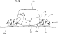
FIG. 12 is a view for explaining an attachment state of a high-pressure air generation unit constituting a foreign matter removal device according to a second embodiment. -
FIGS. 13A, 13B and 13C are perspective views for explaining each attachment member to which the high-pressure air generation unit is attached. -
FIGS. 14A and 14B are views showing modified examples of the attachment member. -
FIGS. 15A shows the high-pressure air generation unit fixed to a back door panel, andFIG. 15B shows a plan view ofFIG. 15A . -
FIG. 16A is a top perspective view ofFIG. 15B , andFIG. 16B is a bottom perspective view ofFIG. 15B . -
FIG. 17A is a top perspective view of the adhesive member, and FIG. I7B is a bottom perspective view of the adhesive member. - Hereinafter, an example of an embodiment according to the present invention will be described in detail with reference to the drawings.
- For example, a foreign matter removal device of the present invention is applied as a device for removing foreign matters such as water droplets, mud and dust adhering to a lens of an in-vehicle camera.
- As shown in
FIGS. 1A and 1B , a foreignmatter removal device 1 is attached to aback door 200A of a vehicle V, for example. The foreignmatter removal device 1 is provided with amotor 55, and a power supply terminal of themotor 55 is connected to a power supply line of a vehicle. For example, with the triggering that a gear of the vehicle V enters a reverse mode, a vehicle control unit (ECU; not shown) causes an in-vehicle camera 100 (to be described later) to start photographing, and the foreignmatter removal device 1 is controlled to operate by the vehicle control unit (ECU) within several seconds at the start of photographing, for example. - The in-
vehicle camera 100 is a camera for confirming, for example, the rear side of the vehicle V and, as shown inFIG. 1C , alens 101 of the in-vehicle camera 100 is attached to theback door 200A so that it is exposed toward the outside of theback door 200A of the vehicle V. The in-vehicle camera 100 is provided with an imaging unit (not shown), and thelens 101 covers the imaging unit. As the lens, a simple translucent cover that does not converge or diffuse light is also included in the lens of this example. - Meanwhile, as shown in
FIGS. 2A and 2B , the foreignmatter removal device 1 may be attached to arear bumper 200B of the vehicle V, for example. Meanwhile, the position at which the in-vehicle camera 100 is attached is not limited to the rear end side of the vehicle but may be a body panel such as the front side or lateral side of the vehicle. Further, in this example, the meaning of the phrase, "to be attached to the body panel," includes, for example, a case where the in-vehicle camera is attached via a vehicle mounted component such as a lamp, a door knob, a mirror, a bumper attached to the body panel and a case where the in-vehicle camera is mounted as a part (as an integral body) of these components. - As shown in
FIG. 3 , the foreignmatter removal device 1 includes anozzle unit 2, a joint member 3, a hose 4, and a high-pressureair generation unit 5. - The
nozzle unit 2 is configured to be removably attached to the in-vehicle camera 100. Thenozzle unit 2 includes anattachment part 21 and anozzle 22. Thenozzle unit 2 is formed of resin material, for example. - The
attachment part 21 is attached to ahousing 102 of the in-vehicle camera 100 so as to cover a top surface of the in-vehicle camera 100. Thenozzle 22 injects high-pressure air toward alens 101 of the in-vehicle camera 100. Thenozzle 22 is formed integrally with theattachment part 21. Thenozzle 22 is provided in such a way that a tip end of thenozzle 22 faces thelens 101 when theattachment part 21 is attached to thehousing 102. Here, the phrase, "formed integrally with," means that an operator can handle thenozzle 22 and theattachment part 21 as an integral part during assembly work. Specifically, for example, thenozzle 22 and theattachment part 21 may be molded of the same material and in the same mold. Alternatively, thenozzle 22 and theattachment part 21 may be respectively molded of separate materials, and then, fitted together and formed integrally, thereby constituting thenozzle unit 2. - The joint member 3 is a member for joining the
nozzle 22 of thenozzle unit 2 and the hose 4. One end portion of the joint member 3 is connected to thenozzle 22 and the opposite end portion thereof is connected to the hose 4. The joint member 3 is formed of resin material, for example. - The hose 4 is a piping member that connects, together with the joint member 3, the
nozzle 22 and a high-pressureair generation unit 5. One end portion of the hose 4 is connected to the joint member 3 and the opposite end portion thereof is connected to adischarge port 50 of the high-pressureair generation unit 5. The hose 4 is formed of, for example, a material such as resin or rubber. - The high-pressure
air generation unit 5 is a unit for generating high-pressure air to be fed to thenozzle 22, The high-pressureair generation unit 5 is attached to a part of a vehicle body at the inside of a vehicle. - As shown in
FIG. 4 , the high-pressureair generation unit 5 includes a housing (case main body) 51 and a moving mechanism (generation unit) 65 disposed inside thehousing 51. The movingmechanism 65 generates high-pressure air. Of a moving direction of apiston 52 in the high-pressureair generation unit 5, a rearward direction that is a direction of feeding out air refers to a feeding direction, and a forward direction that is opposite to the feeding direction refers to a force accumulation direction. - In an initial state before high-pressure air is fed out, the
piston 52 is positioned on the feeding direction side, and arack 53 is positioned in a state where arack portion 53a is engageable with agear portion 54a of apinion 54. - When the driving of the motor (driving source) 55 is started and a driving force of the
motor 55 is transmitted to aworm wheel 57 via aworm 56, thegear portion 54a of thepinion 54 is meshed with therack portion 53a of therack 53. Therefore, therack 53 moves in the force accumulation direction against an urging force of an urging spring (elastic member) 58 in accordance with the rotation of thepinion 54. As therack 53 moves in the force accumulation direction, the meshing between thegear portion 54a and therack portion 53a is released at a predetermined position. The position (position shown inFIG. 4 ) where the meshing between thegear portion 54a and therack portion 53a is released is set as the bottom dead center of thepiston 52. In a state in which thepiston 52 is positioned at the bottom dead center, the air (outside air) flowing into a substantially front half portion (second space) 60b of aninternal space 60 of apiston support portion 59 passes through agap 61b along astep 61a and flows toward a substantially rear half portion (first space) 60a of theinternal space 60. - When the
piston 52 is moved to the bottom dead center, the meshing between thegear portion 54a and therack portion 53a is released, and thepiston 52 is moved in the feeding direction at a speed higher than the moving speed in the force accumulation direction by an urging force of the urgingspring 58. In this way, the air flowing from thesecond space 60b to thefirst space 60a passes through thedischarge port 50 of aconnection protrusion 62 from thefirst space 60a and is fed toward thenozzle 22 of thenozzle unit 2 via the hose 4. At this time, since the diameter of thedischarge port 50 is smaller than that of thepiston support portion 59, the air discharged from thefirst space 60a through thedischarge port 50 is compressed into high-pressure air and is fed out. The movingmechanism 65 repeatedly moves thepiston 52 at a high speed to continuously generate high-pressure air. - As shown in
FIG. 5 , the in-vehicle camera 100 and the high-pressureair generation unit 5 are fixed to a back door panel (an example of the panel member) 200a constituting an outer surface of theback door 200A of the vehicle V, for example. In this example, the in-vehicle camera 100 is disposed outside theback door 200A, and the high-pressureair generation unit 5 is disposed inside an outer panel of theback door 200A. The high-pressureair generation unit 5 is disposed at a position closer to ahinge mechanism 201 of theback door 200A than the in-vehicle camera 100. -
FIG 6A is an enlarged view of the high-pressureair generation unit 5 shown inFIG. 5 .FIG. 6B is a plan view showing the high-pressureair generation unit 5 mounted on anadhesive member 71.FIGS. 7A and 7B show a top perspective view and a bottom perspective view ofFIG. 6B , respectively.FIGS. 8A and 8B are views in which the high-pressureair generation unit 5 inFIGS. 7A and 7B is removed, showing a perspective view of theadhesive member 71 as seen from above and a perspective view thereof as seen from below, respectively. - As shown in
FIG. 6A , thehousing 51 of the high-pressureair generation unit 5 is attached to aback door panel 200a via theadhesive member 71. Theadhesive member 71 has anadhesion surface portion 71A, anadhesion layer 71B, and a mountingportion 71C. - As shown in
FIGS. 7A to 8B , theadhesion surface portion 71A is constituted by a plurality of (three in this example) plate-shaped members separated from each other. Theadhesion layer 71B is formed on the surface of eachadhesion surface portion 71A on the side facing theback door panel 200a. - The
adhesion layer 71B is formed of, for example, a double-sided tape having a predetermined thickness. Theadhesion layer 71B is configured so as to be elastically deformable along at least a part of the surface shape of theback door panel 200a. - The mounting
portion 71C is a portion on which thehousing 51 is mounted. The mountingportion 71C is formed continuously with eachadhesion surface portion 71A via acontinuous portion 73 formed so as to rise upward from eachadhesion surface portion 71A. That is, theadhesion surface portions 71A are connected to each other via the mountingportion 71C and eachcontinuous portion 73. - The mounting
portion 71C is provided with a plurality of (three in this example) connectingportions 72 that connects thehousing 51 and the mountingportion 71C. Each of the connectingportions 72 is configured to be elastically deformable (in a stepwise manner in this example). For example, aplanar attachment part 74 to which thehousing 51 is attached is provided at a leading end of each connectingportion 72. Eachattachment part 74 is provided in such a way that it is inclined in a direction away from theadhesion surface portion 71A as approaching its leading end. The attaching surface of eachattachment part 74 is set at an inclination angle toward the center of gravity of the housing 51 (the high-pressure air generation unit 5) mounted thereon. Thehousing 51 having three attaching surfaces to be affixed to theattachment parts 74 is attached to theattachment parts 74 via an adhesive member such as a double-sided tape, for example. - Therefore, when attaching the
housing 51 mounted on the mountingportion 71C of theadhesive member 71 to theback door panel 200a, thehousing 51 is attached to theback door panel 200a via theadhesive member 71 in surface contact with theback door panel 200a by elastically deforming theadhesion layer 71B of theadhesive member 71. - Further, with the configuration of the
continuous portions 73, the connectingportions 72, and theattachment parts 74, thehousing 51 in a state of being mounted on the mountingportion 71C is held in a state in which a gap h (seeFIG. 6A ) is formed between theadhesion surface portion 71A and thehousing 51. - As shown in
FIG. 7A , thehousing 51 is formed in a substantially rectangular parallelepiped shape. Aconnector part 63 for supplying power to themotor 55 is formed on an upper surface (an example of the second surface) 51A of thehousing 51. Thehousing 51 is configured such that a lower surface (an example of the first surface) 51B on the side opposite to theupper surface 51A on which theconnector part 63 is formed is mounted on the mountingportion 71C of theadhesive member 71 so as to face theback door panel 200a. - As shown in
FIGS. 8A and 8B , theadhesive member 71 is formed in a substantially plate shape. Theadhesive member 71 is made of, for example, resin. Meanwhile, theadhesive member 71 may be made of metal. - When generating high-pressure air in the high-pressure
air generation unit 5, the movingmechanism 65 inside thehousing 51 is configured such that thepiston 52 moves parallel (in a left and right direction inFIG. 6A ) to the surface where theadhesive member 71 is in surface contact with theback door panel 200a. - According to this configuration, the
housing 51 of the high-pressureair generation unit 5 is attached to theback door panel 200a of the vehicle V via the plate-shapedadhesive member 71 including the elasticallydeformable adhesion layer 71B. Theadhesion layer 71B of theadhesive member 71 is elastically deformable along the surface shape of theback door panel 200a of the vehicle V. Therefore, even when theback door panel 200a has a curved portion or an uneven portion, theadhesion layer 71B is deformed along the curved portion or the uneven portion and makes surface contact therewith. Further, since theadhesion surface portion 71A is constituted by three separated members, theadhesion surface portion 71A is easily deformed with respect to the curved portion or the uneven portion of theback door panel 200a and is likely to make surface contact therewith. Therefore, a sufficient contact area for obtaining an adhesive force required for fixing thehousing 51 on theback door panel 200a can be secured, so that the versatility at the time of attaching the high-pressureair generation unit 5 can be improved. - Further, since the gap h is formed between the
adhesion surface portion 71A and thehousing 51, the deformation of theadhesion layer 71B is less susceptible to the influence of the rigidity of thehousing 51 of the high-pressureair generation unit 5. Therefore, theadhesion surface portion 71A is likely to be deformed along the curved portion or the uneven portion of theback door panel 200a, so that the versatility at the time of attaching the high-pressureair generation unit 5 can be further improved. - Further, since the connecting
portions 72 can function as a cushioning member, the sound and vibration due to the operation of the motor (drive source) 55 are difficult to propagate to theback door panel 200a. Therefore, it is possible to suppress the occurrence of abnormal noise due to the operation of themotor 55. Further, the attaching surface of eachattachment part 74 to which thehousing 51 is attached is set at an inclination angle toward the center of gravity of the housing 51 (the high-pressure air generation unit 5). Therefore, the sound and vibration and the like can be effectively absorbed, so that it is possible to suppress the occurrence of abnormal noise due to the operation of themotor 55. - Further, since the in-
vehicle camera 100 and the high-pressureair generation unit 5 are attached to the sameback door panel 200a, the pipeline length of a hose or the like for delivering the high-pressure air generated by the high-pressureair generation unit 5 can be shortened and the versatility at the time of attaching the high-pressureair generation unit 5 can be further improved, as compared with a configuration in which they are attached to different members. - Further, since the high-pressure
air generation unit 5 is disposed at a position closer to thehinge mechanism 201 of theback door 200A than the in-vehicle camera 100, an impact force applied to the high-pressureair generation unit 5 at the time of opening and closing theback door 200A is small, as compared with a configuration in which the high-pressureair generation unit 5 is disposed at a position far from thehinge mechanism 201. In this way, a contact area for obtaining an adhesive force required for fixing thehousing 51 on theback door panel 200a can be reduced. Therefore, it is possible to further improve the versatility at the time of attaching the high-pressureair generation unit 5. - Further, since the
upper surface 51A of thehousing 51 on which theconnector part 63 is formed is a surface that does not face theback door panel 200a of the vehicle V, theconnector part 63 does not become an obstacle to the attachment when attaching thehousing 51 of the high-pressureair generation unit 5 to theback door panel 200a of the vehicle V. Therefore, it is easy to attach thehousing 51 to theback door panel 200a and it is also easy to secure a wiring for power supply. In this way, it is possible to further improve the versatility at the time of attaching the high-pressureair generation unit 5. - Further, since the piston
type moving mechanism 65 is adopted, high-pressure air can be generated by thesmall motor 55. Therefore, the high-pressureair generation unit 5 can be reduced in size and weight, so that thehousing 51 can be sufficiently fixed even by an attachment method using the surface contact of a double-sided tape. In this way, it is possible to further improve the versatility at the time of attaching the high-pressureair generation unit 5. - Further, since the high-pressure air is continuously generated by moving the
piston 52 at a high speed, it is possible to improve the performance of removing foreign matters from thelens 101. Moreover, most of the reaction force applied to thehousing 51 when thepiston 52 is moved at a high speed is parallel to the surface (contact surface) where theadhesive member 71 makes surface contact with theback door panel 200a, and the component of the reaction force in the direction intersecting with the contact surface is relatively small. Therefore, for example, even when thepiston 52 is continuously moved at a high speed and the reaction force at that time is continuously applied to thehousing 51, theadhesive member 71 is prevented from being detached from theback door panel 200a because the force of the component in the direction in which theadhesive member 71 is detached from theback door panel 200a is small. - Next, a modified example of the
adhesive member 71 in the above-described embodiment will be described with reference toFIGS. 9 to 10C . -
FIG. 9 shows a state in which the high-pressureair generation unit 5 is attached to theback door panel 200a via anadhesive member 81 of the modified example.FIG. 10A shows a perspective view of the high-pressureair generation unit 5 connected to theadhesive member 81, as seen from below.FIG. 10B shows a perspective view of theadhesive member 81, as seen from below.FIG. 10C shows an exploded state of the members constituting theadhesive member 81. - The
adhesive member 81 includes anadhesive surface portion 81A, anadhesive layer 81B, and a rubber damper (an example of the connection member) 81C. - The
adhesive surface portion 81A has acentral plate 82 having a polygonal shape (regular hexagonal shape in this example), and a plurality of (three in this example) equally spacedattachment plates 83 extending continuously outward from an outer periphery of thecentral plate 82. Theadhesive surface portion 81A is formed of an iron plate bracket, for example. - The
adhesive layer 81B constituted by, for example, a double-sided tape is formed on the surface of thecentral plate 82 on the side facing theback door panel 200a. Theadhesive layer 81B has a predetermined thickness and is configured to be elastically deformable along at least a part of the surface shape of theback door panel 200a. Each of theattachment plates 83 has aninclined portion 83A provided to be inclined, and aflat portion 83B provided parallel to thecentral plate 82. Theflat portion 83B is provided with anattachment hole 84 to which therubber damper 81C is attached. - The
rubber damper 81C is a rubber member that connects theadhesive surface portion 81A and thehousing 51. The damper may be made of a resin having excellent elasticity. Therubber damper 81C has a disc shape. Afirst groove 85A and asecond groove 85B are provided on an outer peripheral portion of therubber damper 81C. Theattachment hole 84 of theattachment plate 83 of theadhesive surface portion 81A is fitted in thefirst groove 85A. Anattachment hole 51D of a connectingportion 51C of thehousing 51 is fitted in thesecond groove 85B. Ahole 86 penetrating in the upper and lower direction is provided in the central portion of therubber damper 81C. Further, a crank-shaped portion is provided over the entire circumference of therubber damper 81C. - Therefore, when attaching the
housing 51 connected to theadhesive member 81 to theback door panel 200a, thehousing 51 is attached to theback door panel 200a via theadhesive member 81 in surface contact with theback door panel 200a by elastically deforming theadhesive layer 81B of theadhesive member 81. - Further, the
housing 51 in a state of being fixed by therubber damper 81C is held in a state in which a gap h1 (seeFIG. 9 ) is formed between theadhesion surface portion 81A and thehousing 51. Further, for example, a gap h2 is secured between therubber damper 81C and theback door panel 200a. - According to this configuration, since the gap h1 is formed between the
adhesive surface portion 81A and thehousing 51, the deformation of theadhesion layer 81B is less susceptible to the influence of the rigidity of thehousing 51 of the high-pressureair generation unit 5. Therefore, theadhesion surface portion 81A is likely to be deformed along the curved portion or the uneven portion of theback door panel 200a, so that the versatility at the time of attaching the high-pressureair generation unit 5 can be further improved. Further, since therubber damper 81C can be elastically deformed and function as a cushioning member, the sound and vibration due to the operation of themotor 55 are absorbed and are difficult to propagate to the panel member. Therefore, it is possible to suppress the occurrence of abnormal noise due to the operation of themotor 55. - Next, a modified example of the
adhesive surface portion 81A constituting theadhesive member 81 will be described with reference toFIG. 11 . - For example, as shown in
FIG. 11 , anadhesive surface portion 91A of the modified example may have aflange portion 92 that can be bent and deformed. In this case, a double-sided tape (adhesion layer) 91B is formed so as to correspond to the shape of theflange portion 92. - According to this configuration, since the
adhesive surface portion 91A is easily brought into contact with theback door panel 200a by being deformed following the curved portion or the uneven portion of theback door panel 200a particularly at theflange portion 92, the versatility during attachment is further improved. - Next, a second embodiment will be described. The same members as those in the first embodiment are denoted by the same reference numerals, and explanation thereof will be omitted.
-
FIG 12 is a partial enlarged view of the high-pressureair generation unit 5.FIG 13A shows a perspective view of the high-pressureair generation unit 5 connected to anadhesive unit 181, as seen from below.FIG. 13B shows a perspective view of theadhesive unit 181, as seen from below.FIG. 13C shows an exploded state of the members constituting theadhesive unit 181. - As shown in
FIG. 12 , thehousing 51 of the high-pressureair generation unit 5 is attached to theback door panel 200a via theadhesive unit 181. Theadhesive unit 181 includes a fixingmember 181A, anadhesive member 181B, and a plurality of (three in this example) rubber dampers (an example of the connecting member) 181C. - The fixing
member 181A is formed in a plate shape and has acentral plate 182 having a polygonal shape (regular hexagonal shape in this example), and a plurality of (three in this example) equally spacedattachment plates 183 extending continuously outward from an outer periphery of thecentral plate 182. The fixingmember 181A is formed of an iron plate bracket, for example. Meanwhile, the fixingmember 181A may be formed of a resin material. - The
adhesive member 181B constituted by, for example, a double-sided tape is attached on the surface (back surface) of thecentral plate 182 on the side facing theback door panel 200a. Theadhesive member 181B includes an elastically deformable adhesion layer that has a predetermined thickness. Thecentral plate 182 is fixed to theback door panel 200a via theadhesive member 181B. - Each of the
attachment plates 183 has aninclined portion 183A provided to be inclined, and aflat portion 183B provided parallel to thecentral plate 182. Theflat portion 183B is provided with anattachment hole 184 to which therubber damper 181C is attached. Theinclined portion 183A is inclined upward such that a distance d in the vertical direction to thecentral plate 182 is increased away from thecentral plate 182. - Each
rubber damper 181C is formed of a rubber member having elasticity and is configured to connect the fixingmember 181A and thehousing 51. Meanwhile, the damper may be made of a resin having the same elasticity as therubber damper 181C. Therubber damper 181C has a disc shape. Afirst groove 185A and asecond groove 185B are provided on an outer peripheral portion of therubber damper 181C. An inner peripheral portion of theattachment hole 184 of theattachment plate 183 of the fixingmember 181A is fitted in thefirst groove 185A. An inner peripheral portion of theattachment hole 51D of the connectingportion 51C of thehousing 51 is fitted in thesecond groove 185B. A through-hole 186 penetrating in the upper and lower direction is provided in the central portion of therubber damper 181C. Further, therubber damper 181C is provided with a crank-shaped portion 187 over the entire circumference of therubber damper 181C. - When attaching the
housing 51 connected to therubber dampers 181C to theback door panel 200a, thehousing 51 is attached to theback door panel 200a via the fixingmember 181A in surface contact with theback door panel 200a by elastically deforming theadhesive member 181B of thecentral plate 182 along at least a part of the surface shape of theback door panel 200a. - Further, in a state in which the
central plate 182 of the fixingmember 181A is fixed to theback door panel 200a via theadhesive member 181B, and thehousing 51 is connected to therubber dampers 181C, thehousing 51 is held in a state in which a sufficient gap h1 (seeFIG. 12 ) is formed between the fixingmember 181A and thehousing 51. In this case, thehousing 51 is connected to therubber dampers 181C so that the position of the center of thehousing 51 overlaps with the position of the center of theadhesive member 181B. Further, since theinclined portion 183A is inclined in a direction away from theback door panel 200a, in this example, a gap h2 is secured between therubber dampers 181C and theback door panel 200a. - Further, when generating high-pressure air in the high-pressure
air generation unit 5, the movingmechanism 65 inside thehousing 51 is configured such that thepiston 52 moves parallel to the surface where the fixingmember 181A is attached to theback door panel 200a. - According to this configuration, the high-pressure
air generation unit 5 is attached to theback door panel 200a in a state in which the gap h1 is formed between theback door panel 200a and the high-pressureair generation unit 5. Therefore, the sound and vibration due to the operation of themotor 55 of the high-pressureair generation unit 5 are reduced by therubber dampers 181C capable of absorbing the vibration and are difficult to propagate to theback door panel 200a of the vehicle V. In this way, the sound and vibration due to the operation of themotor 55 of the high-pressureair generation unit 5 are prevented from being resonated by theback door panel 200a, and hence, the occurrence of abnormal noise can be suppressed. - Further, the plate-shaped
adhesive member 181B including an elastically deformable adhesion layer can also function as a cushioning member. Therefore, the sound and vibration due to the operation of themotor 55 can be also buffered by theadhesive member 181B, so that the sound and vibration are further difficult to propagate to theback door panel 200a. In this way, the occurrence of abnormal noise due to the operation of themotor 55 is further suppressed. - Further, since each
rubber damper 181C is formed of an elastic member and is provided with the through-hole 186 and the crank-shaped portion 187, therubber damper 181C is likely to be elastically deformed. Each of the plurality ofrubber dampers 181C can disperse and reduce the sound and vibration due to the operation of themotor 55. Moreover, even when an impact is applied to thehousing 51 of the high-pressureair generation unit 5 due to, for example, an external factor such as when opening and closing theback door 200A, eachrubber damper 181C can disperse and reduce the impact. - Further, since the
housing 51 is connected to therubber dampers 181C so that the position of the center of thehousing 51 overlaps with the position of the center of theadhesive member 181B, the sound and vibration due to the operation of themotor 55 can be reduced by being equally dispersed to each of therubber dampers 181C. Therefore, as compared with a case where sound and vibration are unevenly dispersed to therubber dampers 181C, the occurrence of abnormal noise due to the operation of themotor 55 can be suppressed. - Further, since the high-pressure
air generation unit 5 is disposed at a position closer to thehinge mechanism 201 of theback door 200A than the in-vehicle camera 100, an impact force applied to the high-pressureair generation unit 5 at the time of opening and closing theback door 200A is small, as compared with a configuration in which the high-pressureair generation unit 5 is disposed at a position far from thehinge mechanism 201. In this way, it is possible to reduce a contact area for obtaining an adhesive force required for fixing thehousing 51 on theback door panel 200a. Therefore, it is possible to further improve the versatility at the time of attaching the high-pressureair generation unit 5. - Further, since the piston
type moving mechanism 65 is adopted, high-pressure air can be generated by thesmall motor 55. Therefore, the high-pressureair generation unit 5 can be reduced in size and weight, and the sound and vibration due to the operation of the drive source can be reduced. - Further, since the high-pressure air is continuously generated by moving the
piston 52 at a high speed, it is possible to improve the performance of removing foreign matters from thelens 101. Moreover, most of the reaction force applied to thehousing 51 when thepiston 52 is moved at a high speed is parallel to the surface (attaching surface) where the fixingmember 181A is attached to theback door panel 200a, and the component of the reaction force in the direction intersecting with the attaching surface is relatively small. Therefore, for example, even when thepiston 52 is continuously moved at a high speed and the reaction force at that time is continuously applied to thehousing 51, the fixingmember 181A is prevented from being detached from theback door panel 200a because the force of the component in the direction in which the fixingmember 181A is detached from theback door panel 200a is small. - Meanwhile, the structure of the fixing
member 181A is not limited to the above-described configuration. For example, as shown inFIG. 14A , a fixingmember 191A may have aflange portion 192 that can be bent and deformed. In this case, a double-sided tape 191B is formed so as to correspond to the shape of theflange portion 192. - According to this configuration, since the fixing
member 191A is easily brought into contact with theback door panel 200a by being deformed following the curved portion or the uneven portion of theback door panel 200a particularly at theflange portion 192, the versatility during attachment is further improved. - Further, for example, as shown in
FIG. 14B , a fixingmember 195A may have an attachingportion 193 to be attached by bolt fastening. The attachingportion 193 is formed of the same iron plate as the other portion of the fixingmember 195A. - According to this configuration, the occurrence of abnormal noise due to the operation of the
motor 55 can be suppressed by therubber dampers 181C while securely fixing the fixingmember 195A to theback door panel 200a by using a bolt. - Next, a modified example of the fixing
member 181A and the connecting member (rubber damper) 181C in the above-described embodiment will be described with reference toFIGS. 15A to 17B . -
FIG. 15A shows the high-pressureair generation unit 5 attached to theback door panel 200a via anadhesive member 171.FIG. 15B is a plan view showing the high-pressureair generation unit 5 mounted on theadhesive member 171.FIGS.16A and 16B show a top perspective view and a bottom perspective view ofFIG. 15B , respectively.FIGS. 17A and 17B are views in which the high-pressureair generation unit 5 inFIGS. 16A and 16B is removed, showing a perspective view of theadhesive member 171 as seen from above and a perspective view thereof as seen from below, respectively. - As shown in
FIG. 15A , thehousing 51 of the high-pressureair generation unit 5 is attached to theback door panel 200a via theadhesive member 171. Theadhesive member 171 includes a fixingmember 171A, anadhesion layer 171B, and a mountingportion 171C (seeFIG. 17A ). - As shown in
FIGS. 16A to 17B , the fixingmember 171A is constituted by a plurality of (three in this example) plate-shaped members separated from each other. Theadhesion layer 171B is formed on the surface of each fixingmember 171A on the side facing theback door panel 200a. - The
adhesion layer 171B is formed of, for example, a double-sided tape having a predetermined thickness. Theadhesion layer 171B is configured so as to be elastically deformable along at least a part of the surface shape of theback door panel 200a. - The mounting portion (an example of the connecting member) 171C is a portion on which the
housing 51 is mounted. The mountingportion 171C is formed continuously with each fixingmember 171A via acontinuous portion 173 formed so as to rise upward from each fixingmember 171A. That is, the fixingmembers 171A are connected to each other via the mountingportion 171C and eachcontinuous portion 173. The fixingmember 171A and the mountingportion 171C are integrally formed of the same material. - The mounting
portion 171C is provided with a plurality of (three in this example) connectingportions 172 that connects thehousing 51 and the mountingportion 171C. Each of the connectingportions 172 is configured to be elastically deformable (in a stepwise manner in this example). For example, aplanar attachment part 174 to which thehousing 51 is attached is provided at a leading end of each connectingportion 172. Eachattachment part 174 is provided in such a way that it is inclined in a direction away from the fixingmember 171A as approaching its leading end. The attaching surface of eachattachment part 174 is set at an inclination angle toward the center of gravity of the housing 51 (the high-pressure air generation unit 5) mounted thereon. Thehousing 51 having three attaching surfaces to be affixed to theattachment parts 174 is attached to theattachment parts 174 via an adhesive member such as a double-sided tape, for example. - Therefore, when attaching the
housing 51 mounted on the mountingportion 171C of theadhesive member 171 to theback door panel 200a, thehousing 51 is attached to theback door panel 200a via theadhesive member 171 in surface contact with theback door panel 200a by elastically deforming theadhesion layer 171B of theadhesive member 171. - Further, with the configuration of the
continuous portions 173, the connectingparts 172, and theattachment parts 174, thehousing 51 in a state of being mounted on the mountingportion 171C is held in a state in which a gap h3 (seeFIG. 15A ) is formed between the fixingmember 171 A and thehousing 51. - As shown in
FIG. 16A , thehousing 51 is formed in a substantially rectangular parallelepiped shape. Theconnector part 63 for supplying power to themotor 55 is formed on theupper surface 51A of thehousing 51. Thehousing 51 is configured such that thelower surface 51B on the side opposite to theupper surface 51A on which theconnector part 63 is formed is mounted on the mountingportion 171C of theadhesive member 171 so as to face theback door panel 200a. - As shown in
FIGS. 17A and 17B , theadhesive member 171 is formed in a substantially plate shape. Theadhesive member 171 is made of, for example, resin. Meanwhile, theadhesive member 171 may be made of metal. - According to this configuration, since the fixing
member 171A and the mountingportion 171C are integrally formed of the same material, the number of parts can be reduced and the cost can be reduced. - Further, the fixing
member 171A is constituted by a plurality of plate-shaped members separated from each other. Therefore, even when an impact is applied to thehousing 51 of the high-pressureair generation unit 5 due to, for example, an external factor such as when opening and closing theback door 200A, each of the plate-shaped members can disperse and reduce the impact. - Further, since the connecting
portions 172 can function as a cushioning member, the sound and vibration due to the operation of the motor (drive source) 55 are difficult to propagate to theback door panel 200a. Therefore, it is possible to suppress the occurrence of abnormal noise due to the operation of themotor 55. Further, the attaching surface of eachattachment part 174 to which thehousing 51 is attached is set at an inclination angle toward the center of gravity of the housing 51 (the high-pressure air generation unit 5). Therefore, the sound and vibration and the like can be effectively absorbed, so that it is possible to suppress the occurrence of abnormal noise due to the operation of themotor 55. - Further, since the gap h3 is formed between the fixing
member 171A and thehousing 51, the deformation of theadhesion layer 171B is less susceptible to the influence of the rigidity of thehousing 51 of the high-pressureair generation unit 5. Therefore, the fixingmember 171A is likely to be deformed along the curved portion or the uneven portion of theback door panel 200a, so that the versatility at the time of attaching the high-pressureair generation unit 5 can be further improved. - Meanwhile, the present invention is not limited to the above-described embodiments, but can be appropriately deformed or improved. In addition, the materials, shapes, dimensions, numerical values, modes, quantities, and locations and the like of the respective components in the above-described embodiments are arbitrary and not limited as long as they can achieve the present invention.
- For example, in the above examples, the application to the in-vehicle camera has been described. However, the object to which the present invention is applied is not limited as long as it is a camera used outdoors. For example, a camera mounted so as to be exposed to the outside of an airplane, a railroad, a ship, a robot, an outdoor installation object, a building and the like may be included.
- Although the present invention has been described in detail with reference to specific embodiments thereof, it will be apparent to one skilled in the art that various changes and modifications can be made therein without departing from the spirit and scope thereof.
- The present application is based on Japanese Patent Application (Patent Application No.
2015-131871) filed on June 30, 2015 2015-131782) filed on June 30, 2015 -
- 1: Foreign Matter Removal Device, 2: Nozzle Unit, 3: Joint Member, 4: Hose, 5: High-Pressure Air Generation Unit, 21: Attachment Part, 22: Nozzle, 51: Housing, 58: Urging Spring (Elastic Member), 65: Moving Mechanism (Generation Unit), 71: Adhesive Member, 71A: Adhesion Surface Portion, 71B: Adhesion Layer, 71C: Mounting Portion, 72: Connecting portion, 73: Continuous portion, 74: Attachment Part, 81A: Adhesion Surface Portion, 81B: Adhesion Layer, 81C: Rubber Damper (an example of connection member), 82: Central Plate, 83: Attachment Plate, 83A: Inclined Portion, 83B: Flat Portion, 84: Attachment Hole, 85A: First Groove, 85B: Second Groove, 86: Hole, 100: In-Vehicle Camera, 101: Lens, 102: Housing, 200A: Back Door, 200a: Back Door Panel, 201: Hinge Mechanism, V: Vehicle
Claims (27)
- A foreign matter removal device which removes foreign matters on a lens of an in-vehicle camera attached to a vehicle so that the lens of the in-vehicle camera is exposed toward the outside of a body panel of a vehicle, the foreign matter removal device comprising:a high-pressure air generation unit that includes a generation unit having a drive source and configured to generate high-pressure air using the drive source, and a housing covering the generation unit; anda plate-shaped adhesive member that includes an adhesion layer elastically deformable along at least a part of a surface shape of a panel member constituting the vehicle,wherein the housing is attached to the panel member via the adhesive member in surface contact with the panel member.
- The foreign matter removal device according to claim 1, wherein
the adhesive member has an adhesive surface portion on which the adhesion layer is formed, and a mounting portion which is formed continuously with the adhesive surface portion and on which the housing can be mounted, and
a gap is formed between the adhesive surface portion and the housing in a state in which the housing is mounted on the mounting portion. - The foreign matter removal device according to claim 2, wherein
the adhesive surface portion includes at least three plate-shaped members separated from each other, and
the plate-shaped members is connected to each other via the mounting portion. - The foreign matter removal device according to claim 2 or 3, wherein
the mounting portion has a connecting portion that connects the housing and the mounting portion, and
the connecting portion is configured to be elastically deformable. - The foreign matter removal device according to claim 1, wherein
the adhesive member has an adhesive surface portion on which the adhesion layer is at least partially formed, and a connecting member that connects the adhesive surface portion and the housing, and
a gap is formed between the adhesive surface portion and the housing in a state in which the housing is fixed by the connecting member. - The foreign matter removal device according to claim 5, wherein
the connecting member is formed of an elastic material. - The foreign matter removal device according to claim 5 or 6, wherein
the adhesive surface portion has a flange portion that can be bent and deformed. - The foreign matter removal device according to any one of claims I to 7, wherein
the in-vehicle camera and the high-pressure air generation unit are attached to the panel member. - The foreign matter removal device according to any one of claims 1 to 8, wherein
the panel member is a back door panel constituting an outer surface of a back door of the vehicle,
the in-vehicle camera is attached to the back door panel, and
the high-pressure air generation unit is disposed at a position closer to a hinge mechanism of the back door panel than the in-vehicle camera. - The foreign matter removal device according to any one of claims 1 to 9, wherein
the housing has a first surface facing the panel member and a second surface on which a connector part that supplies power to the drive source is formed, and
the second surface is provided as a surface different from the first surface. - The foreign matter removal device according to any one of claims 1 to 10, wherein
the generation unit has a piston and an elastic member, and the generation unit generates the high-pressure air by storing an elastic force of the elastic member by using the drive source and releasing the elastic force to move the piston at a high speed. - The foreign matter removal device according to claim 11, wherein
the generation unit continuously generates the high-pressure air by repeatedly moving the piston at a high speed by using the drive source and the elastic member. - The foreign matter removal device according to claim 11 or 12, wherein
a movement direction of the piston when generating the high-pressure air is parallel to the surface where the adhesive member makes surface contact with the panel member. - A foreign matter removal device which removes foreign matters on a lens, the foreign matter removal device comprising:a high-pressure air generation unit that includes a generation unit having a drive source and configured to generate high-pressure air using the drive source, and a housing covering the generation unit; anda plate-shaped adhesive member that includes an adhesion layer elastically deformable along at least a part of a surface shape of a panel member,wherein the housing is fixed to the panel member via the adhesive member in surface contact with the panel member.
- A vehicle comprising the foreign matter removal device according to any one of claims I to 14.
- A foreign matter removal device which removes foreign matters on a lens of an in-vehicle camera attached to a vehicle so that the lens of the in-vehicle camera is exposed toward the outside of a body panel of a vehicle, the foreign matter removal device comprising:a high-pressure air generation unit that includes a generation unit having a drive source and configured to generate high-pressure air using the drive source, and a housing covering the generation unit,a plate-shaped fixing member fixed to a panel member constituting a vehicle; anda connecting member that connects the fixing member and the high-pressure air generation unit and is capable of absorbing vibration,wherein a gap is formed between the fixing member and the housing in a state in which the fixing member is fixed to the panel member and the housing is connected to the connecting member.
- The foreign matter removal device according to claim 16, wherein
the fixing member is fixed to the panel member via an adhesive member having an elastically deformable adhesion layer. - The foreign matter removal device according to claim 16 or 17, wherein
the connecting member includes a plurality of elastic members. - The foreign matter removal device according to any one of claims 16 to 18, wherein
the fixing member has a flange portion that can be bent and deformed. - The foreign matter removal device according to claim 16, wherein
the fixing member and the connecting member are integrally formed of the same material. - The foreign matter removal device according to claim 20, wherein
the fixing member includes a plurality of plate-shaped members separated from each other, and
the plate-shaped members are connected to each other via the connecting member. - The foreign matter removal device according to any one of claims 16 to 21, wherein
the panel member is a back door panel constituting an outer surface of a back door of the vehicle,
the in-vehicle camera is attached to the back door panel, and
the high-pressure air generation unit is disposed at a position closer to a hinge mechanism of the back door panel than the in-vehicle camera. - The foreign matter removal device according to any one of claims 16 to 22, wherein
the generation unit has a piston and an elastic member, and the generation unit generates the high-pressure air by storing an elastic force of the elastic member by using the drive source and releasing the elastic force to move the piston at a high speed. - The foreign matter removal device according to claim 23, wherein
the generation unit continuously generates the high-pressure air by repeatedly moving the piston at a high speed by using the drive source and the elastic member. - The foreign matter removal device according to claim 23 or 24, wherein
a movement direction of the piston when generating the high-pressure air is parallel to the surface where the fixing member makes surface contact with the panel member. - A foreign matter removal device which removes foreign matters on a lens, the foreign matter removal device comprising:a high-pressure air generation unit that includes a generation unit having a drive source and configured to generate high-pressure air using the drive source, and a housing covering the generation unit,a plate-shaped fixing member fixed to a panel member; anda connecting member that connects the fixing member and the high-pressure air generation unit and is capable of absorbing vibration,wherein a gap is formed between the fixing member and the housing in a state in which the fixing member is fixed to the panel member and the housing is connected to the connecting member.
- A vehicle comprising the foreign matter removal device according to any one of claims 16 to 26.
Applications Claiming Priority (3)
| Application Number | Priority Date | Filing Date | Title |
|---|---|---|---|
| JP2015131781 | 2015-06-30 | ||
| JP2015131782 | 2015-06-30 | ||
| PCT/JP2016/068573 WO2017002688A1 (en) | 2015-06-30 | 2016-06-22 | Foreign matter removal device and vehicle provided with same |
Publications (3)
| Publication Number | Publication Date |
|---|---|
| EP3318453A1 true EP3318453A1 (en) | 2018-05-09 |
| EP3318453A4 EP3318453A4 (en) | 2019-03-27 |
| EP3318453B1 EP3318453B1 (en) | 2020-11-18 |
Family
ID=57608182
Family Applications (1)
| Application Number | Title | Priority Date | Filing Date |
|---|---|---|---|
| EP16817796.2A Active EP3318453B1 (en) | 2015-06-30 | 2016-06-22 | Foreign matter removal device and vehicle provided with same |
Country Status (5)
| Country | Link |
|---|---|
| US (1) | US10556571B2 (en) |
| EP (1) | EP3318453B1 (en) |
| JP (1) | JP6766043B2 (en) |
| CN (1) | CN107709105B (en) |
| WO (1) | WO2017002688A1 (en) |
Cited By (1)
| Publication number | Priority date | Publication date | Assignee | Title |
|---|---|---|---|---|
| CN107433915A (en) * | 2017-07-07 | 2017-12-05 | 浙江大华技术股份有限公司 | A kind of external vehicle mounted imaging apparatus and vehicle |
Families Citing this family (4)
| Publication number | Priority date | Publication date | Assignee | Title |
|---|---|---|---|---|
| JP7153462B2 (en) * | 2017-07-31 | 2022-10-14 | 株式会社デンソーテン | Mounting structure of drive unit |
| EP3677477A4 (en) * | 2017-08-30 | 2022-11-23 | Koito Manufacturing Co., Ltd. | Vehicle cleaner unit, and side turn signal lamp with camera |
| DK180429B1 (en) * | 2018-11-20 | 2021-04-23 | Motional Ad Llc | Self-cleaning sensor housings |
| US20220111822A1 (en) * | 2019-02-01 | 2022-04-14 | Koito Manufacturing Co., Ltd. | Vehicular cleaner |
Family Cites Families (19)
| Publication number | Priority date | Publication date | Assignee | Title |
|---|---|---|---|---|
| JPH03102652A (en) | 1989-09-18 | 1991-04-30 | Canon Inc | Optical information recording and reproducing device |
| US5546630A (en) | 1995-01-04 | 1996-08-20 | Long; Andre | Blast wiper for motor vehicle lights |
| CN2298172Y (en) * | 1997-04-22 | 1998-11-25 | 程元辉 | Vehicle rear-view monitoring device |
| JPH11255018A (en) * | 1998-03-11 | 1999-09-21 | Komatsu Ltd | Device for washing camera for monitoring rear of vehicle |
| JP2001171491A (en) * | 1999-12-16 | 2001-06-26 | Matsushita Electric Ind Co Ltd | On-vehicle camera device and on-vehicle camera cleaning method |
| EP1616762B1 (en) * | 2001-08-31 | 2006-09-27 | Kautex Textron GmbH & Co. KG. | Headlamp cleaning device |
| JP2009083730A (en) * | 2007-10-01 | 2009-04-23 | Panasonic Corp | On-vehicle camera |
| JP4513889B2 (en) | 2008-04-03 | 2010-07-28 | 株式会社日本自動車部品総合研究所 | Camera with washer nozzle and washer nozzle |
| JP5056919B2 (en) | 2009-09-29 | 2012-10-24 | 株式会社デンソー | In-vehicle optical sensor cover and in-vehicle optical sensor device |
| RU2455177C2 (en) * | 2009-09-29 | 2012-07-10 | Денсо Корпорейшн | Onboard optical sensor case and onboard optical sensor |
| US20120117745A1 (en) | 2009-09-29 | 2012-05-17 | Denso Corporation | On-board optical sensor cover and on-board optical sensor apparatus |
| JP2012201122A (en) * | 2011-03-23 | 2012-10-22 | Asmo Co Ltd | Nozzle device for vehicle-mounted camera, vehicle-mounted camera with cleaning device, and cleaning system for vehicle-mounted camera |
| JP5494743B2 (en) | 2011-10-14 | 2014-05-21 | 株式会社デンソー | Camera cleaning device |
| US9707896B2 (en) | 2012-10-15 | 2017-07-18 | Magna Electronics Inc. | Vehicle camera lens dirt protection via air flow |
| US20150114431A1 (en) * | 2013-10-31 | 2015-04-30 | Glacial Blaster, Inc. | Air blast wiper system and method |
| JP6551962B2 (en) | 2013-11-28 | 2019-07-31 | Necエンベデッドプロダクツ株式会社 | In-vehicle camera cleaning apparatus and in-vehicle camera cleaning method |
| CN106163888B (en) | 2014-04-14 | 2019-06-28 | 株式会社小糸制作所 | Foreign substance removing apparatus |
| EP2949520B1 (en) * | 2014-05-27 | 2018-03-21 | Fico Transpar, S.A. | System for cleaning a vehicle-mounted optic lens |
| US10059280B2 (en) * | 2014-06-06 | 2018-08-28 | Joseph Richard Cooper | Obstruction-removal system and method for vehicle-camera lens |
-
2016
- 2016-06-22 WO PCT/JP2016/068573 patent/WO2017002688A1/en unknown
- 2016-06-22 US US15/740,936 patent/US10556571B2/en active Active
- 2016-06-22 CN CN201680038229.1A patent/CN107709105B/en active Active
- 2016-06-22 JP JP2017526307A patent/JP6766043B2/en active Active
- 2016-06-22 EP EP16817796.2A patent/EP3318453B1/en active Active
Cited By (1)
| Publication number | Priority date | Publication date | Assignee | Title |
|---|---|---|---|---|
| CN107433915A (en) * | 2017-07-07 | 2017-12-05 | 浙江大华技术股份有限公司 | A kind of external vehicle mounted imaging apparatus and vehicle |
Also Published As
| Publication number | Publication date |
|---|---|
| JP6766043B2 (en) | 2020-10-07 |
| WO2017002688A1 (en) | 2017-01-05 |
| EP3318453B1 (en) | 2020-11-18 |
| EP3318453A4 (en) | 2019-03-27 |
| US20180194331A1 (en) | 2018-07-12 |
| CN107709105A (en) | 2018-02-16 |
| US10556571B2 (en) | 2020-02-11 |
| JPWO2017002688A1 (en) | 2018-06-21 |
| CN107709105B (en) | 2020-09-08 |
Similar Documents
| Publication | Publication Date | Title |
|---|---|---|
| EP3318453A1 (en) | Foreign matter removal device and vehicle provided with same | |
| US11827188B2 (en) | Foreign material removing device and vehicle provided with this foreign material removing device | |
| EP3318454B1 (en) | Foreign matter removal device and vehicle provided with same | |
| US20180186341A1 (en) | Foreign matter removal device and vehicle equipped with foreign matter removal device | |
| JP5899182B2 (en) | Electric vehicle | |
| JP4728906B2 (en) | Vehicle spoiler structure | |
| US20170082856A1 (en) | Mounting structure for head up display | |
| GB2417012A (en) | A cowl cover for a vehicle | |
| JP2012126152A (en) | Protection device of power control device | |
| JP2020138564A (en) | Head-up display device and attachment structure of the same | |
| JP5468163B2 (en) | Device for fixing the battery module to the body shell of an automobile | |
| JP2010285093A (en) | Bumper cover supporting structure | |
| JP5268702B2 (en) | Body front structure | |
| JP2012144125A (en) | Baffle guide structure for vehicle | |
| JP4669743B2 (en) | Front body structure of automobile | |
| JP2005132325A (en) | Rear bumper assembly structure for vehicle body | |
| JP7141998B2 (en) | Protective member and protective structure | |
| JP2007237901A (en) | Side door structure of automobile | |
| JP7141999B2 (en) | Protective member and protective structure | |
| JP2017206044A (en) | Front surface part structure of cab | |
| JP6460164B2 (en) | Automotive front structure | |
| JP6624010B2 (en) | Vehicle front structure | |
| KR20070066280A (en) | Automobile's bumper | |
| JP2019014290A (en) | Vehicle shroud panel structure and assembly method for the same | |
| JP2019104274A (en) | Washer nozzle fitting structure for surrounding information detection device |
Legal Events
| Date | Code | Title | Description |
|---|---|---|---|
| STAA | Information on the status of an ep patent application or granted ep patent |
Free format text: STATUS: THE INTERNATIONAL PUBLICATION HAS BEEN MADE |
|
| PUAI | Public reference made under article 153(3) epc to a published international application that has entered the european phase |
Free format text: ORIGINAL CODE: 0009012 |
|
| STAA | Information on the status of an ep patent application or granted ep patent |
Free format text: STATUS: REQUEST FOR EXAMINATION WAS MADE |
|
| 17P | Request for examination filed |
Effective date: 20171228 |
|
| AK | Designated contracting states |
Kind code of ref document: A1 Designated state(s): AL AT BE BG CH CY CZ DE DK EE ES FI FR GB GR HR HU IE IS IT LI LT LU LV MC MK MT NL NO PL PT RO RS SE SI SK SM TR |
|
| AX | Request for extension of the european patent |
Extension state: BA ME |
|
| DAV | Request for validation of the european patent (deleted) | ||
| DAX | Request for extension of the european patent (deleted) | ||
| A4 | Supplementary search report drawn up and despatched |
Effective date: 20190222 |
|
| RIC1 | Information provided on ipc code assigned before grant |
Ipc: H04N 5/225 20060101ALI20190218BHEP Ipc: H04N 7/18 20060101ALI20190218BHEP Ipc: B60R 1/00 20060101AFI20190218BHEP Ipc: B60S 1/56 20060101ALI20190218BHEP Ipc: B60S 1/54 20060101ALI20190218BHEP |
|
| REG | Reference to a national code |
Ref country code: DE Ref legal event code: R079 Ref document number: 602016048212 Country of ref document: DE Free format text: PREVIOUS MAIN CLASS: B60S0001600000 Ipc: B60R0001000000 |
|
| RIC1 | Information provided on ipc code assigned before grant |
Ipc: B60S 1/56 20060101ALI20200608BHEP Ipc: H04N 7/18 20060101ALI20200608BHEP Ipc: B60S 1/54 20060101ALI20200608BHEP Ipc: H04N 5/225 20060101ALI20200608BHEP Ipc: B60R 1/00 20060101AFI20200608BHEP |
|
| GRAP | Despatch of communication of intention to grant a patent |
Free format text: ORIGINAL CODE: EPIDOSNIGR1 |
|
| STAA | Information on the status of an ep patent application or granted ep patent |
Free format text: STATUS: GRANT OF PATENT IS INTENDED |
|
| INTG | Intention to grant announced |
Effective date: 20200803 |
|
| GRAS | Grant fee paid |
Free format text: ORIGINAL CODE: EPIDOSNIGR3 |
|
| GRAA | (expected) grant |
Free format text: ORIGINAL CODE: 0009210 |
|
| STAA | Information on the status of an ep patent application or granted ep patent |
Free format text: STATUS: THE PATENT HAS BEEN GRANTED |
|
| AK | Designated contracting states |
Kind code of ref document: B1 Designated state(s): AL AT BE BG CH CY CZ DE DK EE ES FI FR GB GR HR HU IE IS IT LI LT LU LV MC MK MT NL NO PL PT RO RS SE SI SK SM TR |
|
| REG | Reference to a national code |
Ref country code: GB Ref legal event code: FG4D |
|
| REG | Reference to a national code |
Ref country code: CH Ref legal event code: EP |
|
| REG | Reference to a national code |
Ref country code: DE Ref legal event code: R096 Ref document number: 602016048212 Country of ref document: DE |
|
| REG | Reference to a national code |
Ref country code: IE Ref legal event code: FG4D |
|
| REG | Reference to a national code |
Ref country code: AT Ref legal event code: REF Ref document number: 1335416 Country of ref document: AT Kind code of ref document: T Effective date: 20201215 |
|
| REG | Reference to a national code |
Ref country code: AT Ref legal event code: MK05 Ref document number: 1335416 Country of ref document: AT Kind code of ref document: T Effective date: 20201118 |
|
| REG | Reference to a national code |
Ref country code: NL Ref legal event code: MP Effective date: 20201118 |
|
| PG25 | Lapsed in a contracting state [announced via postgrant information from national office to epo] |
Ref country code: FI Free format text: LAPSE BECAUSE OF FAILURE TO SUBMIT A TRANSLATION OF THE DESCRIPTION OR TO PAY THE FEE WITHIN THE PRESCRIBED TIME-LIMIT Effective date: 20201118 Ref country code: GR Free format text: LAPSE BECAUSE OF FAILURE TO SUBMIT A TRANSLATION OF THE DESCRIPTION OR TO PAY THE FEE WITHIN THE PRESCRIBED TIME-LIMIT Effective date: 20210219 Ref country code: PT Free format text: LAPSE BECAUSE OF FAILURE TO SUBMIT A TRANSLATION OF THE DESCRIPTION OR TO PAY THE FEE WITHIN THE PRESCRIBED TIME-LIMIT Effective date: 20210318 Ref country code: RS Free format text: LAPSE BECAUSE OF FAILURE TO SUBMIT A TRANSLATION OF THE DESCRIPTION OR TO PAY THE FEE WITHIN THE PRESCRIBED TIME-LIMIT Effective date: 20201118 Ref country code: NO Free format text: LAPSE BECAUSE OF FAILURE TO SUBMIT A TRANSLATION OF THE DESCRIPTION OR TO PAY THE FEE WITHIN THE PRESCRIBED TIME-LIMIT Effective date: 20210218 |
|
| PG25 | Lapsed in a contracting state [announced via postgrant information from national office to epo] |
Ref country code: IS Free format text: LAPSE BECAUSE OF FAILURE TO SUBMIT A TRANSLATION OF THE DESCRIPTION OR TO PAY THE FEE WITHIN THE PRESCRIBED TIME-LIMIT Effective date: 20210318 Ref country code: PL Free format text: LAPSE BECAUSE OF FAILURE TO SUBMIT A TRANSLATION OF THE DESCRIPTION OR TO PAY THE FEE WITHIN THE PRESCRIBED TIME-LIMIT Effective date: 20201118 Ref country code: LV Free format text: LAPSE BECAUSE OF FAILURE TO SUBMIT A TRANSLATION OF THE DESCRIPTION OR TO PAY THE FEE WITHIN THE PRESCRIBED TIME-LIMIT Effective date: 20201118 Ref country code: BG Free format text: LAPSE BECAUSE OF FAILURE TO SUBMIT A TRANSLATION OF THE DESCRIPTION OR TO PAY THE FEE WITHIN THE PRESCRIBED TIME-LIMIT Effective date: 20210218 Ref country code: AT Free format text: LAPSE BECAUSE OF FAILURE TO SUBMIT A TRANSLATION OF THE DESCRIPTION OR TO PAY THE FEE WITHIN THE PRESCRIBED TIME-LIMIT Effective date: 20201118 Ref country code: SE Free format text: LAPSE BECAUSE OF FAILURE TO SUBMIT A TRANSLATION OF THE DESCRIPTION OR TO PAY THE FEE WITHIN THE PRESCRIBED TIME-LIMIT Effective date: 20201118 |
|
| REG | Reference to a national code |
Ref country code: LT Ref legal event code: MG9D |
|
| PG25 | Lapsed in a contracting state [announced via postgrant information from national office to epo] |
Ref country code: HR Free format text: LAPSE BECAUSE OF FAILURE TO SUBMIT A TRANSLATION OF THE DESCRIPTION OR TO PAY THE FEE WITHIN THE PRESCRIBED TIME-LIMIT Effective date: 20201118 |
|
| PG25 | Lapsed in a contracting state [announced via postgrant information from national office to epo] |
Ref country code: CZ Free format text: LAPSE BECAUSE OF FAILURE TO SUBMIT A TRANSLATION OF THE DESCRIPTION OR TO PAY THE FEE WITHIN THE PRESCRIBED TIME-LIMIT Effective date: 20201118 Ref country code: EE Free format text: LAPSE BECAUSE OF FAILURE TO SUBMIT A TRANSLATION OF THE DESCRIPTION OR TO PAY THE FEE WITHIN THE PRESCRIBED TIME-LIMIT Effective date: 20201118 Ref country code: SM Free format text: LAPSE BECAUSE OF FAILURE TO SUBMIT A TRANSLATION OF THE DESCRIPTION OR TO PAY THE FEE WITHIN THE PRESCRIBED TIME-LIMIT Effective date: 20201118 Ref country code: LT Free format text: LAPSE BECAUSE OF FAILURE TO SUBMIT A TRANSLATION OF THE DESCRIPTION OR TO PAY THE FEE WITHIN THE PRESCRIBED TIME-LIMIT Effective date: 20201118 Ref country code: SK Free format text: LAPSE BECAUSE OF FAILURE TO SUBMIT A TRANSLATION OF THE DESCRIPTION OR TO PAY THE FEE WITHIN THE PRESCRIBED TIME-LIMIT Effective date: 20201118 Ref country code: RO Free format text: LAPSE BECAUSE OF FAILURE TO SUBMIT A TRANSLATION OF THE DESCRIPTION OR TO PAY THE FEE WITHIN THE PRESCRIBED TIME-LIMIT Effective date: 20201118 |
|
| REG | Reference to a national code |
Ref country code: DE Ref legal event code: R097 Ref document number: 602016048212 Country of ref document: DE |
|
| PG25 | Lapsed in a contracting state [announced via postgrant information from national office to epo] |
Ref country code: DK Free format text: LAPSE BECAUSE OF FAILURE TO SUBMIT A TRANSLATION OF THE DESCRIPTION OR TO PAY THE FEE WITHIN THE PRESCRIBED TIME-LIMIT Effective date: 20201118 |
|
| PLBE | No opposition filed within time limit |
Free format text: ORIGINAL CODE: 0009261 |
|
| STAA | Information on the status of an ep patent application or granted ep patent |
Free format text: STATUS: NO OPPOSITION FILED WITHIN TIME LIMIT |
|
| 26N | No opposition filed |
Effective date: 20210819 |
|
| PG25 | Lapsed in a contracting state [announced via postgrant information from national office to epo] |
Ref country code: AL Free format text: LAPSE BECAUSE OF FAILURE TO SUBMIT A TRANSLATION OF THE DESCRIPTION OR TO PAY THE FEE WITHIN THE PRESCRIBED TIME-LIMIT Effective date: 20201118 Ref country code: NL Free format text: LAPSE BECAUSE OF FAILURE TO SUBMIT A TRANSLATION OF THE DESCRIPTION OR TO PAY THE FEE WITHIN THE PRESCRIBED TIME-LIMIT Effective date: 20201118 Ref country code: IT Free format text: LAPSE BECAUSE OF FAILURE TO SUBMIT A TRANSLATION OF THE DESCRIPTION OR TO PAY THE FEE WITHIN THE PRESCRIBED TIME-LIMIT Effective date: 20201118 |
|
| PG25 | Lapsed in a contracting state [announced via postgrant information from national office to epo] |
Ref country code: SI Free format text: LAPSE BECAUSE OF FAILURE TO SUBMIT A TRANSLATION OF THE DESCRIPTION OR TO PAY THE FEE WITHIN THE PRESCRIBED TIME-LIMIT Effective date: 20201118 |
|
| PG25 | Lapsed in a contracting state [announced via postgrant information from national office to epo] |
Ref country code: ES Free format text: LAPSE BECAUSE OF FAILURE TO SUBMIT A TRANSLATION OF THE DESCRIPTION OR TO PAY THE FEE WITHIN THE PRESCRIBED TIME-LIMIT Effective date: 20201118 Ref country code: MC Free format text: LAPSE BECAUSE OF FAILURE TO SUBMIT A TRANSLATION OF THE DESCRIPTION OR TO PAY THE FEE WITHIN THE PRESCRIBED TIME-LIMIT Effective date: 20201118 |
|
| REG | Reference to a national code |
Ref country code: CH Ref legal event code: PL |
|
| GBPC | Gb: european patent ceased through non-payment of renewal fee |
Effective date: 20210622 |
|
| REG | Reference to a national code |
Ref country code: BE Ref legal event code: MM Effective date: 20210630 |
|
| PG25 | Lapsed in a contracting state [announced via postgrant information from national office to epo] |
Ref country code: LU Free format text: LAPSE BECAUSE OF NON-PAYMENT OF DUE FEES Effective date: 20210622 |
|
| PG25 | Lapsed in a contracting state [announced via postgrant information from national office to epo] |
Ref country code: LI Free format text: LAPSE BECAUSE OF NON-PAYMENT OF DUE FEES Effective date: 20210630 Ref country code: IE Free format text: LAPSE BECAUSE OF NON-PAYMENT OF DUE FEES Effective date: 20210622 Ref country code: GB Free format text: LAPSE BECAUSE OF NON-PAYMENT OF DUE FEES Effective date: 20210622 Ref country code: CH Free format text: LAPSE BECAUSE OF NON-PAYMENT OF DUE FEES Effective date: 20210630 |
|
| PG25 | Lapsed in a contracting state [announced via postgrant information from national office to epo] |
Ref country code: IS Free format text: LAPSE BECAUSE OF FAILURE TO SUBMIT A TRANSLATION OF THE DESCRIPTION OR TO PAY THE FEE WITHIN THE PRESCRIBED TIME-LIMIT Effective date: 20210318 |
|
| PG25 | Lapsed in a contracting state [announced via postgrant information from national office to epo] |
Ref country code: BE Free format text: LAPSE BECAUSE OF NON-PAYMENT OF DUE FEES Effective date: 20210630 |
|
| P01 | Opt-out of the competence of the unified patent court (upc) registered |
Effective date: 20230509 |
|
| PG25 | Lapsed in a contracting state [announced via postgrant information from national office to epo] |
Ref country code: CY Free format text: LAPSE BECAUSE OF FAILURE TO SUBMIT A TRANSLATION OF THE DESCRIPTION OR TO PAY THE FEE WITHIN THE PRESCRIBED TIME-LIMIT Effective date: 20201118 |
|
| PG25 | Lapsed in a contracting state [announced via postgrant information from national office to epo] |
Ref country code: HU Free format text: LAPSE BECAUSE OF FAILURE TO SUBMIT A TRANSLATION OF THE DESCRIPTION OR TO PAY THE FEE WITHIN THE PRESCRIBED TIME-LIMIT; INVALID AB INITIO Effective date: 20160622 |
|
| PGFP | Annual fee paid to national office [announced via postgrant information from national office to epo] |
Ref country code: FR Payment date: 20230510 Year of fee payment: 8 Ref country code: DE Payment date: 20230502 Year of fee payment: 8 |
|
| PG25 | Lapsed in a contracting state [announced via postgrant information from national office to epo] |
Ref country code: MK Free format text: LAPSE BECAUSE OF FAILURE TO SUBMIT A TRANSLATION OF THE DESCRIPTION OR TO PAY THE FEE WITHIN THE PRESCRIBED TIME-LIMIT Effective date: 20201118 |